Wireless Touchscreen Installation Guide
|
|
|
- Eustace Jordan
- 6 years ago
- Views:
Transcription

1 Wireless Touchscreen Installation Guide
2
3 Safety Declaration of Conformity The Systemline Wireless Commander has been designed and independently tested to be in compliance with the following standards: EMC in line with the R&TTE directive 1999/5/EC EN V1.8.1 EN V1.2.1 Radio services in line with the R&TTE directive 1999/5/EC EN v1.7.1 Safety serices in line with the R&TTE directive 1999/5/EC EN with combined US and Canadian version of the UL mark culus under UL and IEC This Symbol is to alert the user to the presence of dangerous voltages inside the Systemline Modular Power supplies. To reduce the risk of electric shock do not dismantle these power supplies. This symbol is to alert the user of important operating instructions included on the CD-Rom accompanying the Systemline Modular system. Read all the instructions before connecting or operating the Systemline Modular system. Pay particular attention to the safety information. Keep this manual so you can refer to the safety instructions. WARNING: There are no user serviceable parts inside. Refer all servicing issues to qualified personnel. WARNING: To reduce the risk of fire or electric shock, do not expose the Systemline Modular system to moisture or water. Do not allow foreign object to get into any part of Systemline Modular system. If moisture or foreign bodies get inside any part, immediately disconnect the power cord from the wall. Obtain assistance from a qualified service person. No objects filled with liquids, such as vases, shall be placed on any part of Systemline Modular system. That no naked flame sources such as candles should be placed on any part of Systemline Modular system. Ventilation should not be impeded. Ensure that the Systemline Modular components are fitted in accordance with their individual installation instructions. Copyright and acknowledgements Copyright 2009 Armour Home Electronics Ltd. All rights reserved. The information in this guide is believed to be correct as of the date of publication. However, our policy is one of continuous development and so the information is subject to change without notice, and does not represent a commitment on the part of Armour Home Electronics Ltd. Systemline is a registered trademark of Armour Home Electronics Ltd. All other product names are trademarks or registered trademarks of their respective owners. Stortford Hall Industrial Park Dunmow Road Bishops Stortford Hertfordshire CM23 5GZ Web: About this guide This Wireless Touchscreen Installation Guide is aimed at audio installation engineers, or trained qualified electricians, involved in the actual installation and interconnection of a Systemline system. It is meant to complement the installation manuals for Systemline Modular Advanced or Systemline S6 Multiroom systems. PAGE
4 1 Introduction 5 Commander 5 Charging Station 5 Wireless Junction Box 5 2 Wiring the System for the Commander Introduction Wiring up a Modular zone using SLM3 speakers Wiring up a Modular zone using OW2 on-wall speakers Wiring up a Modular zone using a ZAM unit Wiring up an S6 zone 7 3 Products in Detail 9 Table of Contents 3.1 Wireless Commander Wireless Junction Box Charging Station 10 4 Software Configuration Update Hub Firmware Address All Touch Screens and Wireless Boxes Update Wireless Commander Firmware Configuration Tab Profile Upload Zone Configuration 12 PAGE


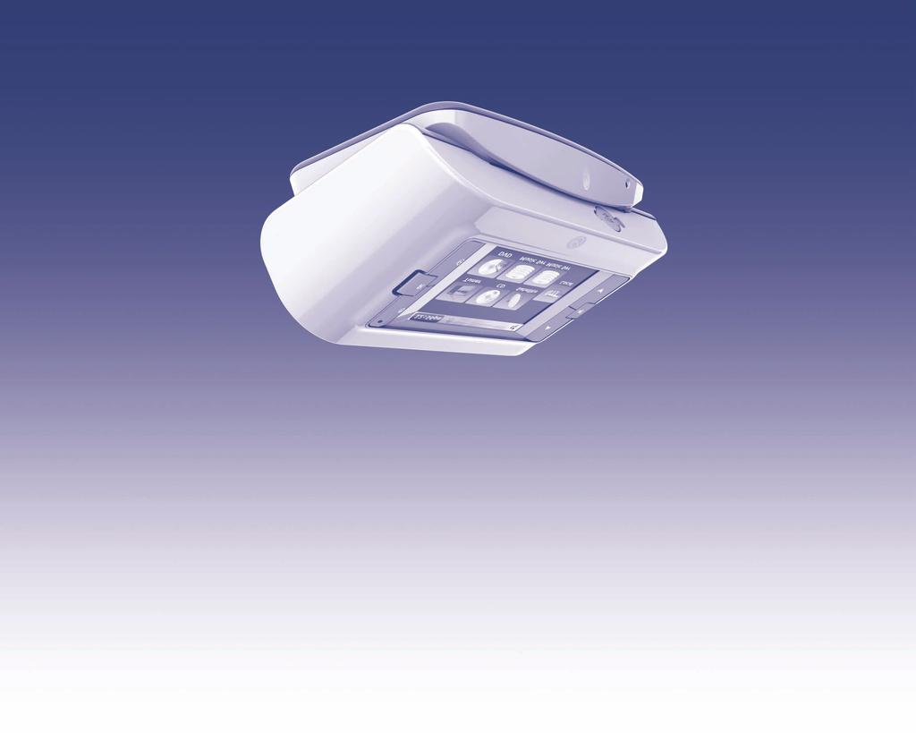
5 1 Introduction The Systemline Wireless Commander can be used with both Modular Advanced and S6 Multi-room systems, giving all the benefits of the wired touch screen in your hand. This manual shows you how to plan, connect and configure wireless Commander touchscreens to your project and should be used in conjunction with the SystemNet 6-port hub instructions included in the Hub or S6 unit. The Commander system consists of three parts: so there can be more than one location for a Commander to recharge. Commander This is the wireless touch screen handset itself and contains a 2.4GHz two way radio interface. The Commander offers all the features supported by the wired touch screen but also has the ability to control any wirelessly enabled zone in the system. The Commander is sold with a matching charging station. Charging Station Wireless Junction Box This is a small unit that contains a 2.4GHz two-way radio interface and all the connectivity to control a Systemline Modular or S6 zone. Every zone that requires wireless Commander control must contain a wireless junction box. This unit is sold separately so you can activate up to 8 zones with one or more Commanders. Section 1 Introduction This unit charges the Commander Touch screen and includes a 9V DC power supply. There is a small blue LED on the front which will illuminate for a period of time when the Commander is docked correctly. This unit is available separately, PAGE
6 2 Wiring the System for the Commander This chapter gives information about preparing and wiring your Systemine S6 or Modular Advance Multi-room system for use with the Wireless Commander. Section 2 Wiring the System 2.1 Introduction The Commander is only compatible with Systemline S6 or Systemline Modular Advanced Multi-room systems (with a 6 port SystemNet Hub). Each zone must have a Wireless Junction Box for it to connect to the wireless system and allow Commander Control. SystemNet supports up to eight Junction Boxes and up to eight Wireless Commanders. This does not affect the number of wired touch screens, which remains up to one per zone with a maximum of eight in total. You can also mix KMP7 or LKPM7 keypads with the Wireless Commander in any zone. It is possible to use a Wireless junction box with no keypad connected, operation by Commander only. The following wiring schematics below only show the SystemNet part of wiring, and not the audio or video wiring which remains unchanged. We have shown an example of the Commander used in each possible Systemline scenario. 2.2 Wiring up a Modular zone using SLM3 speakers the junction box via a single Cat5e cable in the normal way. SLM3 Active Speaker Wireless Junction Box SystemNet Hub CAT5E Cable Wired Touchscreen Keypad (TSK) or KPM7/LKPM7 Keypad Modules The Cat5 wiring requirement for wireless control is the same as a normal wired touch screen zone, so you will just need to replace the current M-SNB with the Wireless junction box behind the active speaker in the ceiling. NOTE: Please beware of metal foil lined ceiling plaster as this could seriously degrade the wireless signal. You will use the following RJ45 sockets on the junction box: Speaker Keypad Wired Keypad (optional) SystemNet Hub The wireless junction box can be used in any zone where control from a Wireless Commander is required. All zones with a wireless junction box can be controlled from one Wireless Commander. A wired touch screen, LKPM7 or KMP7 is optional and not necessary for wireless commander control, but simply wires into PAGE
7 IN L R AUDIO OUT L R SIM 2.3 Wiring up a Modular zone using OW2 onwall speakers 2.4 Wiring up a Modular zone using a ZAM unit Wireless Junction Box Wireless Junction Box Local Input (SIM) CAT5E Cable OW2 On-wall Speaker RJ45 Socket SystemNet Hub Wired Touchscreen Keypad (TSK) or KPM7/LKPM7 Keypad Modules The Modular on-wall speaker M-OW2 does not have enough space to fit the wireless junction box behind it, so a suitable place must be provided with the correct Cat5 cables as shown above. Any wired touch screen or keypad needs a single Cat5 cable to the junction box and not the speaker. The SystemNet Hub Cat5 cable must wire to the junction box and not the speaker. The junction box has a single Cat5 cable to the active on-wall speaker. If a local input is also needed, then this must share the single RJ45 connector on the back of the speaker. The junction box speaker keypad cable requires only the brown and blue pairs, and the local input SIM/WE module requires only the green and orange pairs. You will use the following RJ45 sockets on the junction box: Speaker Keypad Wired Keypad (optional) SystemNet Hub ZAM Zone Amp Module SystemNet Hub CAT5E Cable Wired Touchscreen Keypad (TSK) or KPM7/LKPM7 Keypad Modules The wireless junction box can be placed next to the ZAM unit, as long as the position of the ZAM is central or near by the desired operation of the wireless commander. You will use the following RJ45 sockets on the junction box: Speaker Keypad Wired Keypad (optional) SystemNet Hub 2.5 Wiring up an S6 zone Wired Touchscreen Keypad (TSK) or KPM7/LKPM7 Keypad Modules Wireless Junction Box S6 Controller Section 2 Wiring the System CAT5E Cable The wireless junction box must be placed between the wired touchscreen or keypad and the S6 Controller as shown. Ideally the junction box is still in close proximity PAGE
8 to the zone, so new installations should route the Cat5 cable from the wall keypad to a suitable location first and then to the S6 unit. You will use the following RJ45 sockets on the junction box: Wired Keypad (optional) S6 Section 2 Wiring the System PAGE


9 3 Products in Detail A starter pack will contain all you need to make one zone work with the Wireless Commander. Additional Junction Boxes, Charging Base Stations and Commander Units can be purchased separately to expand the system. 3.1 Wireless Commander The Commander has the same 3.5 VGA colour touch screen as the wired touch screen. It has six hard buttons, three on each side with the following functions. Power: Turns the currently selected zone on or off. Room: Will display all available zones in the system for Commander Control, and allow a new selection. Home: Displays all available sources, and also acts as a menu back function Volume Up: Adjusts the volume up Mute:Mutes the audio Volume Down:Adjusts the volume down There is no IR receiver or room brightness sensor, unlike the wired touch screen. IR signals are sent from the Commander to the Junction Box which then transmits IR back to the Hub or Local input plate. The Commander will switch its backlight off after a set time, and the brightness is adjustable so no room brightness adjustment is needed. The Commander is supplied with a rechargeable NiMH battery pack which is disconnected at the factory. You must unscrew the battery cover and connect the battery before proceeding with the configuration. 1. Unscrew the battery cover 2. Plug in the battery 3. Screw the battery cover back on You should then place the Commander onto the Charging Base Station. The Commander has a USB port behind a rubber flap which is used for configuration uploads from the SystemNet Application software. See section 4.0 for configuration details. In order to conserve battery life, the Commander will firstly switch the backlight off after a set (adjustable) period of time, and then close down the main operation after five minutes. Section 3 Products in Detail The Commander has a built in mercury balance switch which is used to activate the screen quickly when it is picked up. Alternatively, pressing the screen or any hard buttons will also reactivate the screen within 2 seconds. Once active again, you can use it normally. PAGE

10 The brightness and active time can be adjusted by pressing and holding down the volume up, volume down and mute buttons together. The radio antenna is located on the opposite face to the RJ45 connections, so the unit is best positioned with the radio face pointing towards the zone. The system uses 8 different frequencies to communicate with the Commander and will monitor background noise automatically and switch frequency if needed. This is an automatic process and does not need any adjustment or configuration by the installer or end user. Section 3 Products in Detail The brightness active adjustment is a value from 0 to 99 and will adjust in real time so the desired setting can be made easily. This screen brightness will be applied for a set period of time adjustable from 0 to 60 seconds. Once you have made the adjustment, press Apply to make the settings permanent. The touch screen s accuracy can also be adjusted by pressing the Calibrate Touch screen button. You should use this if the screen is not responsive in the correct area. 3.2 Wireless Junction Box The Wireless Junction Box is used for each zone where Wireless Commander control is required. It is contained within a plastic enclosure which can be DIN rail mounted, fixed to a wall, or left freestanding. The four RJ45 connections should be used with RJ45 plugs wired to TIA-568B standard network wiring. PIN Colour 1 White/Orange 2 Orange/White 3 White/Green 4 Blue/White 5 White/Blue 6 Green/White 7 White/Brown 8 Brown/White A Commander can operate any activated zone in the system through the currently connected Junction Box. This allows the user to switch zones, operate lights, volume etc. without having to move from their current position. The Wireless Junction Box has two status LED s showing wireless and wired (hub) data activity. Normally the hub light will flash every second or so, the wireless light should only flash when using a Commander connected to box. If they are not flashing at all or on continuously then you may have a bad connection or severe background RF noise. The wireless junction box will store all IR data for the zone when controlled by a Wireless Commander. IR is then transmitted to the S6 unit or AM8 hub via the speaker or ZAM unit. This makes it possible for the Wireless Commander to operate IR devices, even local devices without directly transmitting IR from the front. Please ensure you upload the.qrc file to each junction box as covered in section Charging Station The charging station is supplied with each Wireless Commander unit and comes with a 9V 2A DC power supply which should be connected to the rear socket. The station contains a moulded recess which matches the outline of the Commander, making it easy to locate the Commander to charge the battery. There are four steel contacts on the charger which connect to the four copper strips on the underside of the Commander. PAGE 10
11 When correctly docked the blue LED on the front of the charging station will illuminate for approximately 15 seconds. The Commander can still be used when docked in the charging station, and does not use any power from the battery in this case. You should find that the Commander docked in the charging station is angled towards the user if mounted on a table or desk. Take care to avoid damaging the charging pins on the Charging Bass Station as this may cause intermittent charging operation. Section 3 Products in Detail PAGE 11

12 4 Software Configuration The Commander system comes with a CD containing the SystemNet Configuration software. You should install this software on your machine before proceeding any further. This step by step instruction should be used in addition to the SystemNet S6 or 6 port Hub instructions and refers to the addition of Wireless Commanders only. Section 4 Software Configuring 4.1 Update Hub Firmware You should update the hub firmware to 12.0 (or higher) before proceeding any further, otherwise the hub or S6 will not recognise Wireless junction boxes. 1. Plug in the USB cable 2. Plug in one wired touch screen 3. Press Query All Keypads 4. The software will return with the keypad address and suggest that firmware is updated. 5. Press Yes and the system will continue updating hub and keypad firmware to version 12.0 or later. 4.2 Address All Touch Screens and Wireless Boxes It is possible to use 8 wired touch screens and 8 Wireless junction boxes in one system, so there are now 16 possible addresses to use and allocate. The Wireless Commander handsets themselves do not have an address, but rather the wireless junction boxes, which are wired into the S6 or 6 port hub unit. The process of allocating addresses is very similar to previous versions but we recommend that you address wireless boxes and wired touch screens on a zone by zone basis. 1. Plug only one zone in to be addressed (this may contain a wired keypad and wireless box). 2. Choose an address for the wired keypad and press Add/Address Keypad. 3. Add a profile if you wish. 4. Choose an address for the wireless box and press Add/Address Wireless. 5. Add a profile if you wish. 6. Disconnect this zone, and then connect the next zone to be addressed and repeat the steps above. 7. Plug in all zones once addressing is complete and press Query All Keypads. You should get a response from all devices with their address and firmware and a prompt to update all firmware versions to the one you are running, proceed with the update. 8. Once the addressing and firmware update is complete, pressing Query All Keypads should give a complete response as shown above. PAGE 12


13 4.3 Update Wireless Commander Firmware You should make sure all Commander Units have your version of firmware, by plugging in one at a time using a USB cable. To PC Time button is pressed. Once the unit has been allocated a code it retains it and will be displayed if any of the above communications occur at the bottom right corner of the Local Hub Network tab page as shown. 1. Unplug from the Hub or S6 (Important as the next step will not work). 2. Select Wireless from the drop down menu in Firmware, Selected keypad. 3. Press Get Firmware Versions 4. Follow the prompt to upgrade firmware if required. 5. Unplug Commander, and repeat the process for all in the project. 4.4 Unique System Identification Code Version 12.0 or above with wireless touch screens use a unique code for each system. This is to prevent cross talk between two systems in close proximity, for example in an apartment above that also has a Systemline wireless zone with the same junction box address. Each communication between a Commnder and a system uses the ID code and must be correct to operate the system. The SystemNet software will allocate an ID code when 1st plugged into an S6 or 6 Port Hub and a Query All Keypads or Set It is vital that the correct system ID is shown when you upload a configuration to a Wireless Commander, otherwise the Commander will not operate your system. Always press Set To PC Time or Query All Keypads to get the ID before you upload to a Wireless Commander, otherwise an error message will be displayed. The system ID is not stored in the.snc file you will save on your PC. This is to prevent the same configuration file being uploaded to multiple systems with the same System ID. It is only stored in the S6 or 6 Port Hub. 4.5 Configuration Tab Add configurable Sources and inputs in the normal way 4.6 Profile Each address can be named in the Description box, and the device type can be selected or changed from Colour, Black & White or Wireless. Please make sure that the profile is correct for each of the addresses that you have in your project. The description given for each wireless Section 4 Software Configuring PAGE 13


14 box will be displayed on the Commander when the room buttons is pressed. connecting the USB cable to a charged Commander. You can then select Upload wireless keypad, and the software will then upload. Section 4 Software Configuring Lighting and heating control can be added in the normal way to any selected wired or wireless keypad. IR data must be loaded into wireless profiles; this is then loaded into the junction box which then transmits the correct IR signal for any IR devices you wish to control. A local input source can be added to each profile in the normal way. 4.7 Upload Zone Configuration You must upload a configuration to each wired touch screen and wireless junction box when connected to an S6 or six port hub unit via the supplied USB cable. You may choose a single address upload or multiple upload. It is possible to configure Wireless Commander Touch screens to operate any number of zones from one to eight. You can select the zones that a wireless screen operates by firstly selecting a wireless zone in the Selected Configuration Profile, then selecting Wireless Zone Control. This will bring up a window with all available wireless zones; you can select any number you wish before proceeding with the Commander upload. PLEASE NOTE: If you make a change to the configuration profile of a wireless zone such as adding a lighting scene button, you must upload the zone configuration to the wireless junction box as well as the wireless Commander; otherwise this new button will not work. To do this quickly, select the wireless junction box profile and select Upload Without IR. This will upload all the required data to the hub for the additional buttons or changes you have made. In this example, the Commander generally used for the garden will also be able to operate all other wireless zones in the system. Once you have selected the zones, make sure you have disconnected the USB cable to the S6 unit or SystemNet Hub before PAGE 14
15 PAGE 15
16 PAGE 16
17 PAGE 17
18 PAGE 18
19

20 w w w. s y s t e m l i n e. c o. u k Stortford Hall Industrial Park, Dunmow Road, Bishops Stortford, Hertfordshire CM23 5GZ United Kingdom Web: info@armourhome.co.uk Our policy is one of continuous product improvement, we reserve the right to change the designs and specifications without notice. All information is given in good faith. The manufacturer accepts no responsibility for errors, omissions or incorrect assumptions. Armour Home Electronics 2009 ZINS158/ISS2/151009
SMART Hi-Fi AUDIO *MFL * SJ8 SIMPLE MANUAL. Wireless Multi-room Sound Bar
 ENGLISH SIMPLE MANUAL SJ8 SMART Hi-Fi AUDIO Wireless Multi-room Sound Bar Please read this manual carefully before operating your set and retain it for future reference. To view the instructions of advanced
E100 User Guide. Built-in DAB+, FM & Bluetooth Hi-Fi sound system SE0120 SE0150
 E100 User Guide Built-in DAB+, FM & Bluetooth Hi-Fi sound system SE0120 SE0150 1.0 Important Safety Instructions CAUTION: To reduce the risk of electric shock, do not remove the cover. No user-serviceable
OWNER S MANUAL SINGLE CAT5E/6 3D EXTENDER B-320-1CAT-HDIR
 OWNER S MANUAL SINGLE CAT5E/6 3D EXTENDER B-320-1CAT-HDIR IMPORTANT SAFETY INSTRUCTIONS WARNING: To reduce the risk of fire or electric shock, do not expose this apparatus to rain or moisture. 1. Read
LIFESTYLE ROOMMATE POWERED SPEAKER SYSTEM. Owner s Guide Guía de usuario Notice d utilisation
 LIFESTYLE ROOMMATE POWERED SPEAKER SYSTEM Owner s Guide Guía de usuario Notice d utilisation TAB 8 TAB 7 TAB 6 TAB 5 TAB 4 TAB 3 TAB 2 English SAFETY INFORMATION Please read this owner s guide Please take
Transceiver Hub with Integral Camera Power
 Passive UTP Transceiver Hub with Integral Installation Guide Models Include: HubWay8CD HubWay16CD - UL Listed eight (8) Channel Passive UTP - UL Listed sixteen (16) Channel Passive UTP Transceiver Hub
Passive UTP Transceiver Hub with Integral Isolated Camera Power Installation Guide
 Passive UTP Transceiver Hub with Integral Isolated Installation Guide Models Include: HubWay8Di HubWay16Di - UL Listed eight (8) Channel Passive UTP - UL Listed sixteen (16) Channel Passive UTP Transceiver
Active UTP Transceiver Hub with Integral Camera Power Installation Guide
 Active UTP Transceiver Hub with Integral Installation Guide Models Include: HubWayLD8CDS - UL Listed eight (8) Channel Active UTP Transceiver Hub with Integral HubWayLD82CDS - UL Listed eight (8) Channel
OWNER S MANUAL SINGLE CAT5E/6 3D EXTENDER B-200-1CAT-HDIR. Receiver
 OWNER S MANUAL SINGLE CAT5E/6 3D EXTENDER B-200-1CAT-HDIR Receiver IMPORTANT SAFETY INSTRUCTIONS WARNING: To reduce the risk of fire or electric shock, do not expose this apparatus to rain or moisture.
Active UTP Transceiver Hub with Integral Isolated Camera Power
 Active UTP Transceiver Hub with Integral Isolated Installation Guide HubWayEX16SP - UL Listed sixteen (16) Channel Active UTP Transceiver Hub with Integral Isolated Rev. 011810 More than just power. TM
WIRELESS BLUETOOTH BOOMBOX
 G-BOOM WIRELESS BLUETOOTH BOOMBOX Wireless Bluetooth Rugged Construction Rechargeable Battery USB Device Charging G-650 Welcome to G-PROJECT Thanks for purchasing G-BOOM and joining G-Project. With just
Active UTP Transceiver Hub with Integral Isolated Camera Power Installation Guide
 Active UTP Transceiver Hub with Integral Isolated Installation Guide Models Include: HubWayLD8Di HubWayLD16Di - UL Listed eight (8) Channel Active UTP - UL Listed sixteen (16) Channel Active UTP Transceiver
AB-315. ibus Wall-Dock for A-Bus Audio Systems
 AB-315 ibus Wall-Dock for A-Bus Audio Systems TM By 10 The AB-315 is an on-wall ipod docking station for A-BUS audio systems. The dock connector slides in and out to adjust for any ipod and the non-skid
Keypad KEY-2.7. Instruction Manual
 Keypad KEY-2.7 Instruction Manual Precautions 2 1. Read these instructions. 2. Keep these instructions. 3. Heed all warnings. 4. Follow all instructions. 5. Do not use this apparatus near water. 6. Never
TOT Series Manual. North American and International Models - without optional faceplate. Receptacle Panel of International Models, CE model shown
 TOT Series Manual North American and International Models - without optional faceplate Receptacle Panel of International Models, CE model shown North American Models Table of Content 1. Important Safety
Document Part Number: Rev. 01 (December 2009) TouchTunes and the TouchTunes logo are trademarks of TouchTunes Interactive Networks.
 TouchTunes and the TouchTunes logo are trademarks of TouchTunes Interactive Networks.") Document Part Number: 9002211-001 Rev. 01 (December 2009) Disclaimer TouchTunes and the TouchTunes logo are trademarks of TouchTunes Interactive Networks. All other brand and product names are trademarks
Document Part Number: 9002211-001 Rev. 01 (December 2009) Disclaimer TouchTunes and the TouchTunes logo are trademarks of TouchTunes Interactive Networks. All other brand and product names are trademarks
KS-SB200 BOOM BOX INSTRUCTIONS LVT B [J]
![KS-SB200 BOOM BOX INSTRUCTIONS LVT B [J]](/thumbs/72/66806114.jpg "KS-SB200 BOOM BOX INSTRUCTIONS LVT B [J]") BOOM BOX KS-SB200 INSTRUCTIONS For Customer Use: Enter below the Model No. and Serial No. which are located either on the rear, bottom or side of the cabinet. Retain this information for future reference.
BOOM BOX KS-SB200 INSTRUCTIONS For Customer Use: Enter below the Model No. and Serial No. which are located either on the rear, bottom or side of the cabinet. Retain this information for future reference.
SOUNDSTICKS WIRELESS. Setup Guide. Downloaded from
 SOUNDSTICKS WIRELESS Setup Guide English Japanese Simplified Chinese 2 SOUNDSTICKS WIRELESS 1. Read these instructions. 2. Keep these instructions. 3. Heed all warnings. 4. Follow all instructions. 5.
TOT Series Manual. North American CE and UK Models. CE Models. UK Models. North American Models
 TOT Series Manual North American CE and UK Models CE Models UK Models North American Models Table of Content 1. Important Safety Instructions 2. Description Shipping Carton & Packing Material Placement
Bluetooth integrated amplifier. USER Guide Model s GDI-BTAR122 & GDI-BTAR502
 Bluetooth integrated amplifier USER Guide Model s GDI-BTAR122 & GDI-BTAR502 Important Safety Instructions and Warnings Please read before installation WARNING: CAUTION: To reduce the risk of fire or electrical
Always there to help you. Register your product and get support at DS1600. Question? Contact Philips.
 Always there to help you Register your product and get support at www.philips.com/support Question? Contact Philips DS1600 User manual Contents 1 Important 2 Safety 2 Notice 2 2 Your Docking Speaker 4
PORTABLE SPEAKER & AMPLIFIER USER MANUAL
 PORTABLE SPEAKER & AMPLIFIER USER MANUAL TABLE OF CONTENTS Safety Instructions Important Safety Instructions...2 USB Charging USB Charging...14 Getting to Know the IGNT-2 What s in the Box...4 Getting
A0326. ARIA Audio Streaming Source Receiver with a built in Bluetooth 4.2 Module. ARIA Audio
 A0326 ARIA Audio Streaming Source Receiver with a built in Bluetooth 4.2 Module ARIA Audio by 2017 Model A0326 Channel Vision s ARIA Audio Streaming Receiver is equipped with a Blue tooth 4.2 module, users
+Cam Quick Start Guide
 CAUTION RISK OF ELECTRIC SHOCK DO NOT OPEN CAUTION TO REDUCE THE RISK OF ELECTRIC SHOCK, DO NOT REMOVE COVER (OR BACK). NO USER SERVICEABLE PARTS INSIDE, REFER SERVICING TO QUALIFIED SERVICE PERSONNEL.
Daily use. indicating that the loud speakers
 BeoLab 8002 Guide WARNING: To reduce the risk of fire or electric shock, do not expose this appliance to rain or moisture. Do not expose this equipment to dripping or splashing and ensure that no objects
BeoLink Active. Setting-up Guide
 BeoLink Active Setting-up Guide 2 CAUTION RISK OF ELECTRIC SHOCK DO NOT OPEN CAUTION: To reduce the risk of electric shock, do not remove cover (or back). No User-serviceable parts inside. Refer servicing
User`s Guide SBAR-51. Sound Bar and Docking Station
 User`s Guide SBAR-51 Sound Bar and Docking Station Please read the following instructions carefully before connecting, operating or adjusting this product. Please keep this manual in a convenient place
3D Blu-ray / DVD Home Theater System
 ENGLISH SIMPLE MANUAL 3D Blu-ray / DVD Home Theater System To view the instructions of advanced features, visit http://www.lg.com and then download Owner s Manual. Some of the content in this manual may
Owner s Manual. Isolate. Restore. Inspire! Power Conditioners Audio / Video Power Isolation Units Rack Mount / Consumer Series
 Owner s Manual 19 Pro Series Rack Mount (RK) Faceplate Isolate. 17 Consumer Series (C) Faceplate Available in Black (B) and Silver (S) Colours Restore. Power Conditioners Audio / Video Power Isolation
BRN WHT/BRM BLU WHT/BLU GRN WHT/GRN ORG WHT/ORG
 IN OUT 1 2 3 4 WHT/ WHT/ by Audio In IR Emitters AB-404 AB-301 AB-124 A-BUS Audio System By 12 by The Channel Vision A-BUS Audio system can distribute high-quality audio to every room in your house over
smartentry Wireless Video Doorphone User Manual
 smartentry Wireless Video Doorphone User Manual Designed & Engineered Version 1.2 in the United Kingdom Contents Precautions... 3 1. Product Overview... 4 1.1. Product Features... 4 1.2. Contents... 4
Media Drive 600 User Guide
 Media Drive 600 User Guide EN Important safety instructions Read these instructions. Keep these instructions. Heed all warnings. Follow all instructions. Do not use this apparatus near water. Clean only
1/4 Guitar / Mic input
 1/4 Guitar / Mic input Important Safety Instructions 1) Read these instructions All the safety and operating instructions should be read before this product is operated. 2) Keep these instructions The
DALI Gateway 5502DAL. Installation Instructions
 DALI Gateway 5502DAL Installation Instructions Contents 1.0 Product Range...3 2.0 Description...3 3.0 Features...3 4.0 C-Bus Indicators...4 4.1 Unit/Comms Indicator...4 4.2 C-Bus Indicator...4 5.0 Wiring
INSTRUCTION/INSTALLATION SHEET lyriq Studio High Performance Keypad
 1. Introduction The, P/N AU5010-xx (see Figure 1), is an integral part of the lyriq Multi-Room Audio System. It is a component which, when combined with other essential components (a Source Input Unit,
Cluster FX-Bar. Portable performance lighting and laser rig
 Cluster FX-Bar Portable performance lighting and laser rig Due to continuous product development, please ensure that you have downloaded the latest instruction manual for this product from the AVSL website
Model #28599 Wireless Bluetooth Surround Bar & Subwoofer 285W
 Model #28599 Wireless Bluetooth Surround Bar & Subwoofer 285W User manual & Safety Guide Thank you for choosing Pure Acoustics. We hope you enjoy each and every use of this product. We suggest that you
Quick Guide. ENC-H Video Encoder XX
 Quick Guide ENC-H264-16 Video Encoder XX298-20-00 Vicon Industries Inc. does not warrant that the functions contained in this equipment will meet your requirements or that the operation will be entirely
INSTRUCTION MANUAL DISTRIBUTION UNIT. Please read this manual thoroughly before use, and keep it handy for future reference.
 INSTRUCTION MANUAL DISTRIBUTION UNIT Please read this manual thoroughly before use, and keep it handy for future reference. ISSUE 1 May 2006 LIMITATION OF LIABILITY THE INFORMATION IN THIS PUBLICATION
Plug-in wireless speaker
 JBL Soundfly BT Plug-in wireless speaker Quick Setup Guide Welcome Thank you for purchasing the JBL Soundfly BT plug-in wireless speaker. Soundfly BT will fill your room with sound from your portable Bluetooth-enabled
THIS PAGE LEFT BLANK
 SOUND LEVEL LIMITER THIS PAGE LEFT BLANK IMPORTANT Installer and Users please note: These instructions should be read carefully and left with the user of the product for future reference. The must be installed
BT Duet 210. User Guide
 BT Duet 210 User Guide Welcome. to your BT Duet 210 Corded Telephone 10 number quickdial memory - for ease of dialling your most important telephone numbers Mute mutes your voice so you can talk to someone
Passive UTP Transceiver Hub with Integral Camera Power Installation Guide
 Passive UTP Transceiver Hub with Integral Installation Guide Models Include: HubWay8D HubWay16D - Eight (8) Channels - Sixteen (16) Channels HubWay82D HubWay162D - HubWay8 w/eight (8) HubWayAv - HubWay16
Network Camera. Quick Guide DC-B1203X. Powered by
 Network Camera Quick Guide DC-B1203X Powered by Safety Precautions English WARNING RISK OF ELECTRIC SHOCK DO NOT OPEN WARNING: TO REDUCE THE RISK OF ELECTRIC SHOCK, DO NOT REMOVE COVER (OR BACK). NO USER-SERVICEABLE
A Watt Stereo Amplifier
 A0240 40 Watt Stereo Amplifier 8 The A0240 is a 2-channel 40 Watt class D amplifier. It can be used to power a small 1-room audio system or integrated with Channel Vision s A0302 to provide supplemental
SMART Hi-Fi AUDIO *MFL * SJ9 SIMPLE MANUAL. Wireless Multi-room Sound Bar
 ENGLISH SIMPLE MANUAL SJ9 SMART Hi-Fi AUDIO Wireless Multi-room Sound Bar Please read this manual carefully before operating your set and retain it for future reference. To view the instructions of advanced
Voca safety instructions
 Voca Voca safety instructions 1. Read these instructions All the safety and operating instructions should be read before this product is operated. 2. Keep these instructions The safety and operating instructions
1. Product Description. 2. Product Overview
 1. Product Description Avantree Pluto Air is a multi-function Bluetooth speaker with high quality music performance and mini compact design. This mini speaker can allow you to stream music from Bluetooth-enabled
Always there to help you. Register your product and get support at DS1600/12. Question? Contact Philips.
 Always there to help you Register your product and get support at www.philips.com/support Question? Contact Philips DS1600/12 User manual Contents 1 Important 2 Safety 2 Notice 2 2 Your Docking Speaker
FUSION MS-RA70/MS-RA70N Installation Instructions
 FUSION MS-RA70/MS-RA70N Installation Instructions Important Safety Information WARNING Failure to follow these warnings and cautions could result in personal injury, damage to the vessel, or poor product
INSTRUCTION/INSTALLATION SHEET lyriq Studio Keypad
 1. Introduction The Volume Control, P/N AU5009-xx (see Figure 1), is an integral part of the lyriq Multi-Room Audio System. It is a component which, when combined with other essential components (a Source
ClockWatch. User Manual. Cueing and Presentation Control Specialists
 ClockWatch User Manual Cueing and Presentation Control Specialists Contents: Introduction 3 Environmental / Electrical Compliance 3 Safety Instructions 4 Diagrams 5 Regulations Compliance 6 Operating Instructions
TVA2.1 2-Channel Digital Amplifier Installation Manual
 TVA2.1 2-Channel Digital Amplifier Installation Manual SAFETY INSTRUCTIONS WARNING: TO REDUCE THE RISK OF FIRE OR ELECTRIC SHOCK, DO NOT EXPOSE THIS APPLIANCE TO RAIN OR MOISTURE. CAUTION: TO REDUCE THE
TruVision IP Thermal Camera Installation Guide
 TruVision IP Thermal Camera Installation Guide P/N 1073335-EN REV B ISS 19OCT17 Copyright Trademarks and patents Manufacturer Certification 2017 United Technologies Corporation, Interlogix is part of UTC
5 B&W Rear View System Camera
 5 B&W Rear View System Camera Instruction Manual MODEL: CA453 www.lorexcctv.com Copyright 2007 LOREX Technology Inc. Thank you for purchasing the Lorex 5 Black & White Rear View System Camera. This system
BLUETOOTH SPEAKER BLUEBEAT GSB 110
 BLUETOOTH SPEAKER BLUEBEAT GSB 110 EN 2 8 + A AUX IN MICRO USB 3 5 SET-UP AND SAFETY 5 RF Exposure Warning 5 Important battery information Warning 6 OVERVIEW 6 Bluetooth device compatibility 6 Controls
Wireless Audio Soundbar
 SKIDDAW Wireless Audio Soundbar SKD-BAR-BLK Instructions Guide Contents Controls And Functions... 1 What s In The Box?... 4 Support...5 Instructions Guide... 6 Fixing the Soundbar... 6 Mode Indicator lights...
A0362. Bluetooth 4.2 Receiver Module For Aria Audio System. ARIA Audio
 A0362 Bluetooth 4.2 Receiver Module For Aria Audio System ARIA Audio by 2018 Model A0362 Channel Vision s ARIA Audio Streaming Receiver is equipped with a Blue tooth 4.2 module, users will enjoy further
Active UTP Transceiver Hub with Integral Camera Power Installation Guide
 Active UTP Transceiver Hub with Integral Installation Guide Models Include: HubWayLD8D HubWayLD16D - Eight (8) Channels - Sixteen (16) Channels HubWayLD82D HubWayLD162D - HubWayLD8D w/eight (8) HubWayAv
2 Mesa Ethernet Dock User s Manual
 owner s manual Mesa Ethernet Dock The Mesa Ethernet Dock is an optional accessory that provides an ethernet port for networking, power input jack, USB client port, and a mounting station for the Mesa Rugged
BreezeMAX Wi² and BreezeACCESS Wi² Quick Installation Guide
 This Quick Installation Guide is intended for experienced installers. For more information refer to the relevant sections in the BreezeMAX Wi² and BreezeACCESS Wi² System Manual. Wi² Package Content Check
Media Core 600 User Guide
 Media Core 600 User Guide EN Important safety instructions Read these instructions. Keep these instructions. Heed all warnings. Follow all instructions. Do not use this apparatus near water. Clean only
BS 181 SINGLE CHANNEL POWER SUPPLY USER MANUAL
 BS 181 SINGLE CHANNEL POWER SUPPLY USER MANUAL August 2016 This product is designed and manufactured by: ASL Intercom B.V. Zonnebaan 42 3542 EG Utrecht The Netherlands Phone: +31 (0)30 2411901 Fax: +31
WA-210. Wall Mounted Amplifier with USB/FM and Bluetooth. Item ref: UK, UK User Manual. Version 1.0
 WA-210 Wall Mounted Amplifier with USB/FM and Bluetooth Item ref: 953.131UK, 953.136UK User Manual Version 1.0 Introduction Caution: Please read this manual carefully before operating Damage caused by
ENVIRONMENTAL PROTECTION
 ENVIRONMENTAL PROTECTION Do not dispose of this product with the normal household waste at the end of its life cycle. Return it to a collection point for the recycling of electrical and electronic devices.
UK s best selling phone brand. User Guide. BT Duet 210. Corded Phone
 UK s best selling phone brand User Guide BT Duet 210 Corded Phone Welcome. to your BT Duet 210 Corded Telephone 10 number quickdial memory - for ease of dialling your most important telephone numbers Mute
All company and product names are or Registered Trademarks of their respective owners.
 Install guide No part of this documentation may be reproduced in any form whatsoever or be stored in any data retrieval system without prior written permission of the copyright owners. This documentation
BLUETOOTH SPEAKER GSB 2000
 BLUETOOTH SPEAKER GSB 2000 EN CONTENT ---------------------------------------------------------------------------------------------------------------------------------------- 3 SET-UP AND SAFETY 3 RF Exposure
HDBaseT EXTENDER B-520-TX-230-IR B-520-TX-330-IR INSTALLATION MANUAL
 HDBaseT EXTENDER B-50-TX-30-IR B-50-TX-330-IR INSTALLATI MANUAL IMPORTANT SAFETY INSTRUCTIS To reduce the risk of fire or electric shock, read and follow all instructions and warnings in this manual. Keep
A0326. Bluetooth 4.2 Receiver Module For Aria Audio System. ARIA Audio
 A0326 Bluetooth 4.2 Receiver Module For Aria Audio System ARIA Audio by 2018 Model A0326 Channel Vision s ARIA Audio Streaming Receiver is equipped with a Blue tooth 4.2 module, users will enjoy further
USP-070-B08 USP-104-B10, USP-104-M10 USP-156-B10
 UniStream HMI Panel Installation Guide USP-070-B10, USP-070-B08 USP-104-B10, USP-104-M10 USP-156-B10 Unitronics UniStream platform comprises control devices that provide robust, flexible solutions for
Square D Clipsal Pascal Automation Controller
 Square D Clipsal Pascal Automation Controller SLC5500PACA For Use with Wired C-Bus Networks Instruction Bulletin Retain for future use. Square D Clipsal Pascal Automation Controller 63249-420-258A2 Instruction
8 Button RS232/IR. Control Panel. MuxLab Inc A / SE A
 8 Button RS232/IR Control Panel 500816 MuxLab Inc. 2016 94-000833-A / SE-000833-A SAFETY PRECAUTIONS To insure the best use from the product, please read all instructions carefully before using the device.
Always there to help you. Register your product and get support at BT5580 BT5880. Question? Contact Philips.
 Always there to help you Register your product and get support at www.philips.com/support Question? Contact Philips BT5580 BT5880 User manual Contents 1 Important 2 2 Your Bluetooth speaker 3 Introduction
Kam StarWash Multicolour wash effects with green & red star cluster laser
 Kam StarWash Multicolour wash effects with green & red star cluster laser M A N U A L V E R S I O N 1. 0 0 8-1 6 Due to continuous product development, please ensure that you have downloaded the latest
User Guide. MA-129 ipod & iphone docking station
 User Guide MA-129 ipod & iphone docking station IMPORTANT SAFETY INFORMATION CAUTION! RISK OF ELECTRIC SHOCK DO NOT OPEN TO REDUCE THE RISK OF ELECTRIC SHOCK DO NOT REMOVE COVER (OR BACK) This symbol
Aura Screen. Configuration & Installation Guide
 Aura Screen Configuration & Installation Guide Copyright No part of this publication may be reproduced, transcribed, transmitted, stored in a retrieval system or translated into any language, in any form
Always there to help you. Register your product and get support at SB365B. Question? Contact Philips.
 Always there to help you Register your product and get support at www.philips.com/support Question? Contact Philips SB365B User manual Contents 1 Important 2 Safety 2 2 Your Bluetooth speaker 3 Introduction
USB 2.0 SR. Extender over one CAT-5 Cable. User Manual EXT-USB2.0-SR. Version A1
 USB 2.0 SR Extender over one CAT-5 Cable EXT-USB2.0-SR User Manual Version A1 Important Safety Instructions 1. Read these instructions. 2. Keep these instructions. 3. Heed all warnings. 4. Follow all instructions.
A0326. Bluetooth 4.2 Receiver Module For Aria Audio System. ARIA Audio
 A0326 Bluetooth 4.2 Receiver Module For Aria Audio System ARIA Audio by 2018 Model A0326 Channel Vision s ARIA Audio Streaming Receiver is equipped with a Blue tooth 4.2 module, users will enjoy further
Always there to help you. Register your product and get support at HTL2101X. Question? Contact Philips.
 Always there to help you Register your product and get support at www.philips.com/support Question? Contact Philips HTL2101X User manual Contents 1 Important 2 Safety 2 Care for your product 3 Care of
Safety. Features 1 ID: Make all the connections before you plug in the main power. DMX512 Controllable and RDM Configurable
 Features DMX512 Controllable and RDM Configurable Designed for driving LED strips through 6 high power 12 and 24 Volts output units available Easy addressing interface (physical switches and RDM) Isolated
MATRIX 2 Podule. Description
 MATRIX 2 Podule Description Used as the heart of a distributed audio system, as the main router for a multi room system or as part of a complex boardroom system, the Ikon Matrix 2 Podule offers an easily
NanoServ. Setup Guide. Thin System/Ultra-Thin System. 1.0 What s included with the NanoServ. 2.0 Steps for setting up the NanoServ
 NanoServ Thin System/Ultra-Thin System Setup Guide 1.0 What s included with the NanoServ The following items are included with the NanoServ : 1. NanoServ 2. AC Power Adaptor 3. CD-ROM with User s Manual
INSTRUCTION/INSTALLATION SHEET lyriq High Performance Keypad Volume Control With IR
 1. Introduction The Volume Control with IR, P/N AU1000-xx (see Figure 1), is an integral part of the lyriq Multi-Room Audio System. It is a component which, when combined with other essential components
CR6S Stereo Micro Crush
 1 THANK YOU! Thank you for choosing Orange. You are now a member of the Legendary British Guitar Amplifier owners club! Since 1968 when the company was founded, Orange has been a pioneering force in the
AMP20. User Manual.
 AMP20 User Manual www.audac.eu 2 Index Introduction 5 Precautions 6 Safety requirements 6 Caution servicing 7 EC Declaration of Conformity 7 Waste of Electrical and Electronic Equipment (WEEE) 7 Chapter
Always there to help you. Register your product and get support at BT7500B. Question? Contact Philips.
 Always there to help you Register your product and get support at www.philips.com/support Question? Contact Philips BT7500B User manual Contents 1 Important 2 2 Notice 3 Compliance 3 Care of the environment
01/09/12. WB5326 Wireless Bridge Quick Start Guide
 01/09/12 WB5326 Wireless Bridge Quick Start Guide Quick Start Guide WB5326 Outdoor Wireless Bridge Items Included in Kit (1) WB5326 RADIO (1) PoE (48V, 1A) (1) Mounting Hardware Accessories (1) Quick Start
CS-1 Active Full Range Integrated Commercial Audiovisual System
 Active Full Range Integrated Commercial Audiovisual System User Manual SAFETY INSTRUCTIONS PLEASE READ THROUGH THIS MANUAL FIRST BEFORE OPERATING THE CS-1 SYSTEM. Thank you for purchasing this Beta3 product
MXA2080. Stereo Power Amplifier. Owner s Manual
 MXA2080 Stereo Power Amplifier Owner s Manual CONTENTS Introduction 2 Installation and Safety 2 Power Inlet 3 Smart My-Link Input/output 3 Line Input 3 Line Output 3 Loudspeaker Output 3 Remote Trigger
Innovative K5 Palm Size LED Projector.
 Innovative K5 Palm Size LED Projector www.innovative.com.sg 1 CONTENT COMPONENTS OF PROJECTOR... 2 SPECIFICATIONS... 3 CHARGING THE PROJECTOR... 3 SET UP... 4 POWERING UP AND VIEWING MEDIA... 4 ADJUSTING
XTS36 Touch Screen X10 Lighting Control System Operating Manual
 X10 Lighting Control System Operating Manual 1 X10 Lighting Control System Operating Manual Rev 1.2 Introduction...3 Software Overview...4 How to Install...5 USB Driver Installation...6 Configuration Software
Audio Core 200 User Guide
 Audio Core 200 User Guide 2 EN Important safety instructions Read these instructions. Keep these instructions. Heed all warnings. Follow all instructions. Do not use this apparatus near water. Clean only
KILBURN - PORTABLE ACTIVE STEREO SPEAKER USER MANUAL
 KILBURN - PORTABLE ACTIVE STEREO SPEAKER USER MANUAL Apple TV, Airport Express, iphone, ipod, ipod Classic, ipod Nano, ipod Shuffle, ipod Touch, ipad and Safari are trademarks of Apple Inc., registered
USB 2.0 RG port USB m Cat 5e Extender System. User Guide
 USB 2.0 RG2204 4-port USB 2.0 100m Cat 5e Extender System User Guide Thank you for purchasing the USB 2.0 RG2204. Please read this guide thoroughly. This document applies to Part Numbers: 01-00294, 01-00295,
B&W RearView Camera Installation & Operation
 B&W RearView Camera Installation & Operation CA52 (Camera) FOR MORE INFORMATION WWW.STRATEGICVISTA.COM BEFORE OPERATING THIS SYSTEM, PLEASE READ THIS MANUAL THOROUGHLY AND RETAIN IT FOR FUTURE REFERENCE
ShoreTel IP Phone 655. Quick Install Guide & Warranty
 ShoreTel IP Phone 655 Quick Install Guide & Warranty Document and Software Copyrights Copyright 1998-2012 by ShoreTel Inc., Sunnyvale, California, USA. All rights reserved. Printed in the United States
MODEL 805 USER MANUAL
 MODEL 805 USER MANUAL All Rights Reserved Page 1 of 12 UNPACKING & INSPECTION Save all packing materials they are required for returns and warranty service. Inspect the 805 and packing materials for any
TECHCONNECT TC2-HDMI14 OWNERS MANUAL
 TECHCONNECT TC2-HDMI14 OWNERS MANUAL www.visionaudiovisual.com/techconnect/tc2-hdmi14 1 DECLARATION OF CONFORMITY Where applicable Vision products are certified and comply with all known local regulations
Bluetooth Hands-Free Speaker Phone Custom Accessories 23685
 Bluetooth Hands-Free Speaker Phone Custom Accessories 23685 1. Product Description This versatile Bluetooth speakerphone is specially designed for the user to enjoy convenient and free wireless communication.