solutions for teaching and learning
|
|
|
- Derrick Greene
- 6 years ago
- Views:
Transcription
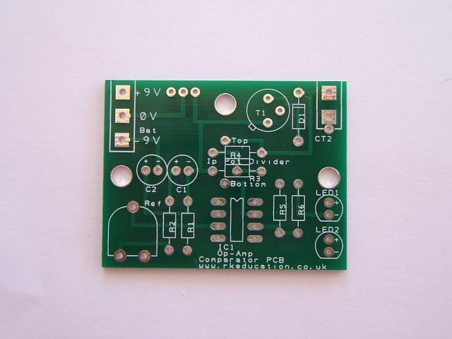
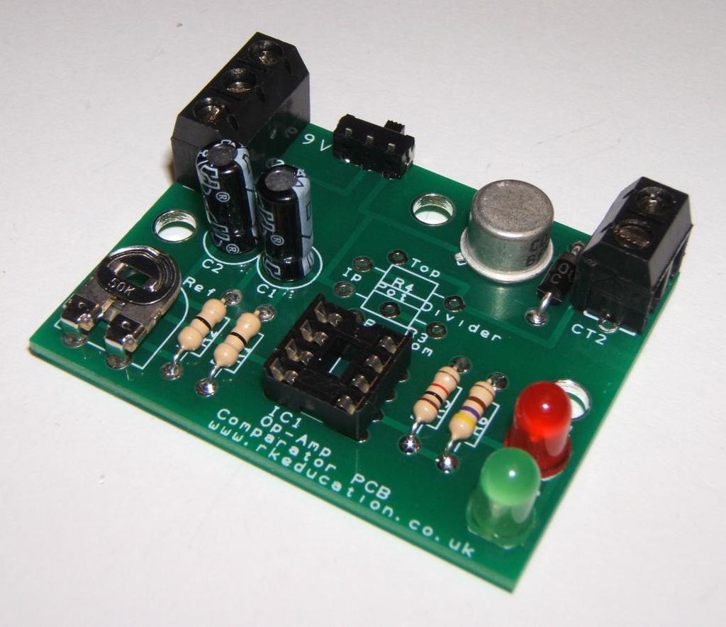
1 Circuit Construction Op-Amp Comparator Project The circuit diagram on the right is the circuit for your project, it is called an op-amp comparator circuit, it is called a comparator circuit as it compares its 2 inputs, inverting and non-inverting, if the voltage at the noninverting input is bigger the output goes to +9V and if the inverting input voltage is bigger the output goes to -9V, this has the effect of changing the LED that is lit, it also turns the motor on and off. The example shown uses a thermistor but the circuit can also use an LDR for light level sensing or a moisture sensor. The thermistor could also be swopped with the 10k resistor in the potential divider. Construction of circuit Circuit example, see below for a schematic You will need to collect the following equipment before you start soldering your circuit: Soldering iron and stand Damp sponge Solder wire Side cutters Pliers Components: Q1 BFY51 transistor C1, C2 10uF capacitor* D1 1N4007 diode** IC1 IC holder and 741, CA3140 op-amp IC R1, R2 0R* R3, R4 This is the potential divider and what is used will depend on what the circuit is being used for, e.g. light/dark sensing, hot/cold sensing R5 1k resistor (brown, black, red)** R6 470R resistor (yellow, violet, brown) Ref 1k preset resistor* Power switch Bat Battery clips, a 3 way terminal block may be used, this circuit uses a dual supply so 2 battery clips are needed CT2 Output, a terminal block should be used here, your output can be inserted into the terminal block LEDs The LEDs used will depend on your project outcome If a higher quality finish is required then use 5mm 2 way terminal blocks, these will add extra cost * These components can be varied ** These components can be left out Op-Amp Comparator Project Page 1
2 This project PCB has been designed with maximum flexibility in mind and how it is constructed will depend on what it is you are aiming to achieve with it, for example a teacher or lecturer completing a project with a number of students will probably use it in a different way to a hobbyist with a specific task in mind. The circuit has a drive circuit that utilises a BFY51 transistor but if it is not required it is quite acceptable to leave this section out. If a buzzer is required a PCB mount buzzer can be inserted into the component marked CT2, a shorting link or 0R resistor will need to be used to connect pin 6 of the op-amp timer to the buzzer. This should be soldered between the lower part of R5 and the lower part of D1. The circuit has space for 2 LEDs but 1 can be left out as required and if an output is being used then they both may be left out. If an output is being used, for example a DC motor then this should be inserted into the terminal block marked CT2, a back EMF diode has been included. To allow the level at which the comparator changes state to be varied the circuit uses a variable resistor Ref, this can either be PCB mount or an external panel mount type. There are 2 fixed resistors R1, R2 that placed with the Ref resistor, if they are not required use 0R. How the circuit is constructed is very much dependent on what it is being used for. Procedure for construction 1. Solder the resistors into your PCB, take care to insert the correct resistor into the correct place, if in doubt ask your teacher. When soldering be sure to heat the area sufficiently but not too much as it will damage the PCB. 2. Solder the remainder of the PCB mounting components in place. 3. Solder your power switch in place 4. Solder your battery clips in place 5. Solder your LEDs into the PCB, if you have attached flying leads insert these, be sure to get the LED the correct way around, remember the long and short legs The order in which you solder and what you solder is dependent on your final outcome, always start with the lowest profile components, for example the resistors. Please visit our website If you have any comments or queries please us at technical@rkeducation.co.uk Op-Amp Comparator Project Page 2
3 Op-Amp Comparator Project Page 3
4 Op-Amp Comparator Project Page 4

5 Op-Amp Comparator Project Page 5
RKP08 Component List and Instructions
 RKP08 Component List and Instructions PCB layout Constructed PCB RKP08 Scematic RKP08 Project PCB Page 1 Description The RKP08 project PCB has been designed to use PIC microcontrollers such as the Genie
solutions for teaching and learning
 RKAmp1 Component List and Instructions PCB layout Constructed PCB Schematic RKAmp1 Stereo Amplifier Page 1 Description The RKAmp1 stereo amplifier PCB has been designed around the 2 x 1watt stereo amplifier
solutions for teaching and learning
 RKOneAnalogue Component List and Instructions PCB layout Constructed PCB Schematic Diagram RKOneAnalogue Software Development PCB Page 1 Description The RKOneAnalogue software development PCB has been
solutions for teaching and learning
 RKP18Motor Component List and Instructions PCB layout Constructed PCB Schematic Diagram RKP18Motor Project PCB Page 1 Description The RKP18Motor project PCB has been designed to use PIC microcontrollers
Build Your Own Home Security System
 Build Your Own Home Security System Student Lab Guide Engineering Teaching Laboratory Name Date Lab Partner(s) NEW TERMS Electric Circuit: Electric circuits are paths for transmitting electric current,
IR TRANSMITTER BLOK PCB ASSEMBLY INSTRUCTIONS. Copyright EduTek Ltd Rev. 2
 IR TRANSMITTER BLOK PCB ASSEMBLY INSTRUCTIONS Copyright EduTek Ltd Rev. 2 Circuit Details The circuit is shown below with a parts list of components. Check through this list and identify each component.
solutions for teaching and learning
 RKAmp3 Component List and Instructions PCB layout Constructed PCB Schematic RKAmp3 Stereo Amplifier Page 1 Description The RKAmp3 stereo amplifier PCB has been designed around the 2 x 7watt stereo amplifier
MP3 audio amplifier. Build Instructions. Issue 2.0
 MP3 audio amplifier Build Instructions Issue 2.0 Build Instructions Before you put any components in the board or pick up the soldering iron, just take a look at the Printed Circuit Board (PCB). The components
3 pyro output datalogger altimeter with an ATmega 328 microcontroller Kit assembly instructions
 3 pyro output datalogger altimeter with an ATmega 328 microcontroller Kit assembly instructions Version date Author Comments 1.0 29/05/2013 Boris du Reau Initial version Rocket Type Micro-max Model Mid
BehringerMods.com. Instructions for modification of Behringer SRC analog inputs and outputs
 BehringerMods.com Instructions for modification of Behringer SRC analog inputs and outputs The following instructions will cover the details of fully modifying a unit with analog output and analog input
Electronics Construction Manual
 Electronics Construction Manual MitchElectronics 2018 Version 1 07/05/2018 www.mitchelectronics.co.uk CONTENTS Introduction 3 How To Solder 4 Resistors 5 Capacitors 6 Diodes and LEDs 7 Switches 8 Transistors
PICAXE EXPERIMENTER BOARD (AXE090)
") (AXE00) Description: The PICAXE experimenter board allows circuits for any size/revision of PICAXE chip ( / / ) to be quickly tested using a prototyping breadboard. The experimenter board provides power
(AXE00) Description: The PICAXE experimenter board allows circuits for any size/revision of PICAXE chip ( / / ) to be quickly tested using a prototyping breadboard. The experimenter board provides power
Electronics Construction Manual
 Electronics Construction Manual MitchElectronics 2019 Version 3 04/02/2019 www.mitchelectronics.co.uk CONTENTS Introduction 3 How To Solder 4 Resistors 5 Capacitors 6 Diodes and LEDs 7 Switches 8 Transistors
DIY Line Tracking Smart Car with AT89C2051
 DIY Line Tracking Smart Car with AT89C2051 1. Introduction: A DIY Smart Car design involves mechanical structure, electronic based sensor principle, automatic control, and even knowledge of microcontroller
The Basic Counter. Hobby Electronics Soldering Kit. Instruction Guide
 The Basic Counter Hobby Electronics Soldering Kit Instruction Guide TM For the best outcome, follow each step in order. We recommend reading this guide entirely before you get started. Tools required:
XYLOPHONE KIT ESSENTIAL INFORMATION. Version 2.0 CREATE YOUR OWN ELECTRONIC MUSICAL INTRUMENT WITH THIS
 ESSENTIAL INFORMATION BUILD INSTRUCTIONS CHECKING YOUR PCB & FAULT-FINDING MECHANICAL DETAILS HOW THE KIT WORKS CREATE YOUR OWN ELECTRONIC MUSICAL INTRUMENT WITH THIS XYLOPHONE KIT Version 2.0 Build Instructions
Chill Interface PCB Assembly Instructions
 ExcelValley Chill Interface PCB Waveblaster Module MIDI Interface Board Chill Limited Edition V2 Assembly Kit Standalone midi interface board for Waveblaster synthesizer modules. Suitable for most Waveblaster
DELUXE STEREO AMPLIFIER KIT
 ESSENTIAL INFORMATION BUILD INSTRUCTIONS CHECKING YOUR PCB & FAULT-FINDING MECHANICAL DETAILS HOW THE KIT WORKS CREATE YOUR OWN SPEAKER DOCK WITH THIS DELUXE STEREO AMPLIFIER KIT Version 2.0 Build Instructions
ELECTRONIC DICE CHIP FACTORY ELECTRONIC DICE PROJECT. What is a microcontroller? Example use of a microcontroller.
 1 ELECTRONIC DICE What is a microcontroller? A microcontroller is often described as a 'computer-on-a-chip'. It can be used as an electronic brain to control a product, toy or machine. The microcontroller
Electronic Coin Toss
 1 Electronic Coin Toss Why this circuit? This circuit was not designed for people who can make up their mind nor have a coin to use for a heads or tail coin toss. This circuit can also be used to ask it
Universal Keying Adapter 3+
 Universal Keying Adapter 3+ The Universal Keying Adapter Version 3+ kit will allow you to key nearly any transmitter or transceiver with a straight key, electronic keyer, computer serial or parallel port
SRI-02 Speech Recognition Interface
 SRI-02 Speech Recognition Interface Data & Construction Booklet The Speech Recognition Interface SRI-02 allows one to use the SR-07 Speech Recognition Circuit to create speech controlled electrical devices.
Connecting LEDs to the ADB I/O
 Application Note AN-2 By Magnus Pettersson September 26 1996 Connecting LEDs to the I/O Introduction The following notes are for those of you who are a bit inexperienced with hardware components. This
Pacific Antenna Easy TR Switch Kit
 Pacific Antenna Easy TR Switch Kit Kit Description The Easy TR Switch is an RF sensing circuit with a double pole double throw relay that can be used to automatically switch an antenna between a separate
TKEY-1. CW touch key. (no electromechanical contacts) Assembly manual. Last update: June 20,
 Assembly manual. Last update: June 20,") TKEY-1 CW touch key (no electromechanical contacts) Assembly manual Last update: June 20, 2017 ea3gcy@gmail.com Updates and news at: www.ea3gcy.com Thanks for constructing the TKEY-1A CW touch key Have
TKEY-1 CW touch key (no electromechanical contacts) Assembly manual Last update: June 20, 2017 ea3gcy@gmail.com Updates and news at: www.ea3gcy.com Thanks for constructing the TKEY-1A CW touch key Have
Button Code Kit. Assembly Instructions and User Guide. Single Button Code Entry System
 Button Code Kit Single Button Code Entry System Assembly Instructions and User Guide Rev 1.0 December 2009 www.alan-parekh.com Copyright 2009 Alan Electronic Projects Inc. 1. Introduction... 4 1.1 Concept
Deep Vibes. Wobbly Optical Vibe action
 Deep Vibes Wobbly Optical Vibe action Contents of this document are 2018 Pedal Parts Ltd. No reproduction permitted without the express written permission of Pedal Parts Ltd. All rights reserved. Important
High Power (15W + 15W) Stereo Amplifier
 Stereo Amplifier") High Power (15W + 15W) Stereo Amplifier Build Instructions Issue 1.0 Build Instructions Before you put any components in the board or pick up the soldering iron, just take a look at the Printed Circuit
High Power (15W + 15W) Stereo Amplifier Build Instructions Issue 1.0 Build Instructions Before you put any components in the board or pick up the soldering iron, just take a look at the Printed Circuit
UF-3701 Power Board Construction Guide
 Page 1/5 Soldering and Part Placement See the Chapter 3 of the MIT 6270 Manual for information on electronic assembly, including soldering techniques and component mounting. Construction Information All
Pacific Antenna Two Tone Generator
 Pacific Antenna Two Tone Generator Description Our Two Tone Generator kit provides two non-harmonic, sine wave signals for testing audio circuits Outputs of approximately 700Hz and 1900Hz and the combination
Thursday, September 15, electronic components
 electronic components a desktop computer relatively complex inside: screen (CRT) disk drive backup battery power supply connectors for: keyboard printer n more! Thursday, September 15, 2011 integrated
Engineering Diploma Resource Guide ST450 ETP Electronic Circuits (Engineering)
") Engineering Diploma Resource Guide ST40 ETP Electronic Circuits (Engineering) Introduction Electronics makes a fundamental difference to modern life. The birth of this technology is a story of the twentieth
Engineering Diploma Resource Guide ST40 ETP Electronic Circuits (Engineering) Introduction Electronics makes a fundamental difference to modern life. The birth of this technology is a story of the twentieth
Light Dependent Resistor Circuit by VK4ION
 1 Light Dependent Resistor Circuit by VK4ION Building a Simple Light Dependent circuit using 7 components This circuit detects darkness and allows the LED to turn on See Image 1 and note hand written amendments
USB Controlled DMX interface
 USB Controlled DMX interface Control DMX fixtures using a PC and USB interface. Stand-alone test function that outputs all 512 channels at a time, with adjustable levels. Total solder points: 117 Difficulty
Installation/assembly manual for DCC/Power shield
 Installation/assembly manual for DCC/Power shield The DCC circuit consists of the following components: R1/R6 R2/R3 R4/R5 D1 C2 2 kω resistor ½ Watt (colour code Red/Black/Black/Brown/Brown) 10 kω resistor
Goal: We want to build an autonomous vehicle (robot)
") Goal: We want to build an autonomous vehicle (robot) This means it will have to think for itself, its going to need a brain Our robot s brain will be a tiny computer called a microcontroller Specifically
Goal: We want to build an autonomous vehicle (robot) This means it will have to think for itself, its going to need a brain Our robot s brain will be a tiny computer called a microcontroller Specifically
ME 3210: Mechatronics Signal Conditioning Circuit for IR Sensors March 27, 2003
 ME 3210: Mechatronics Signal Conditioning Circuit for IR Sensors March 27, 2003 This manual and the circuit described have been brought to you by Adam Blankespoor, Roy Merril, and the number 47. The Problem:
Post Tenebras Lab. Written By: Post Tenebras Lab
 Post Tenebras Lab PTL-ino is an Arduino comptaible board, made entirely out of through-hole components. It is a perfect project to learn how to solder and start getting into the world of micro controllers.
Schematic Diagram: R2,R3,R4,R7 are ¼ Watt; R5,R6 are 220 Ohm ½ Watt (or two 470 Ohm ¼ Watt in parallel)
") Nano DDS VFO Rev_2 Assembly Manual Farrukh Zia, K2ZIA, 2016_0130 Featured in ARRL QST March 2016 Issue Nano DDS VFO is a modification of the original VFO design in Arduino Projects for Amateur Radio by
Nano DDS VFO Rev_2 Assembly Manual Farrukh Zia, K2ZIA, 2016_0130 Featured in ARRL QST March 2016 Issue Nano DDS VFO is a modification of the original VFO design in Arduino Projects for Amateur Radio by
The GENIE Light Kit is ideal for introducing simple lighting projects, such as an electronic die, a wearable badge or a night-time warning system.
 Introduction 1 Welcome to the GENIE microcontroller system! The GENIE Light Kit is ideal for introducing simple lighting projects, such as an electronic die, a wearable badge or a night-time warning system.
Test Procedure: Fault Finding Circuits
 Test Procedure: Fault Finding Circuits 1 Test Procedure: Fault Finding Circuits Known as TROUBLE SHOOTING in USA and Far East 2 BEFORE STARTING SAFETY TEST EQUIPMENT DOCUMENTATION 3 BEFORE STARTING SAFETY
MAIN PCB (The small one)
") THANKS FOR CHOOSING ONE OF OUR KITS! This manual has been written taking into account the common issues that we often find people experience in our workshops. The order in which the components are placed
THANKS FOR CHOOSING ONE OF OUR KITS! This manual has been written taking into account the common issues that we often find people experience in our workshops. The order in which the components are placed
LCD Prototype Circuit on Solderless Breadboard. 840 Pin Solderless Breadboard (http://www.digikey.com/ # ND)
") Solderless Breadboard Tutorial Cornerstone Electronics Technology and Robotics I Week 3 Solderless Breadboards: o Solderless breadboards are commonly used in experimentation or to make a prototype of a
Solderless Breadboard Tutorial Cornerstone Electronics Technology and Robotics I Week 3 Solderless Breadboards: o Solderless breadboards are commonly used in experimentation or to make a prototype of a
Images Scientific OWI Robotic Arm Interface Kit (PC serial) Article
 Article") Images Scientific OWI Robotic Arm Interface Kit (PC serial) Article Images Company Robotic Arm PC Interface allows real time computer control and an interactive script writer/player for programming and
Images Scientific OWI Robotic Arm Interface Kit (PC serial) Article Images Company Robotic Arm PC Interface allows real time computer control and an interactive script writer/player for programming and
Digital LED Flasher. Students will be assembling an LED Flasher assembled on a custom printed Circuit Board. Figure 1
 Digital LED Flasher Students will be assembling an LED Flasher assembled on a custom printed Circuit Board Figure 1 Abstract: Students will be assembling a printed circuit board that contains the components
KDR00101 DMX Controlled Relay Kit
 KDR00101 DMX Controlled Relay Kit This is a DMX512-A relay kit using ANSI approved RJ-45 connectors for DMX networks. Power requirements are 12 Vdc @ 100 ma. The relay contact rating is 10 Amp @ 120 or
What are output transducers An output transducer will convert electrical signals passed to it by the process into another form of energy.
 What are output transducers An output transducer will convert electrical signals passed to it by the process into another form of energy. ACTIVITY Can you find the symbols of the output components listed
Advanced Strobe 1.0 Kit
 Kit Instruction Manual Eastern Voltage Research, LLC December 2013, Rev 1 1 http://www.easternvoltageresearch.com Kit Introduction to the Kit Thank you for purchasing the Kit. If you are looking for a
Bill of Materials: 8x8 LED Matrix Driver Game PART NO
 8x8 LED Matrix Driver Game PART NO. 2171031 This Game Maker II kit is a game design platform using a single color 8x8 matrix LED without the need for a shift register or expensive Arduino. The kit includes
Uzebox Kit Assembly Guide
 Uzebox Kit Assembly Guide V1.3 Page 1 of 18 Revision History Version Date Author Description 1.0 01-Nov-2012 A.Bourque Initial release 1.1 6-Nov-2012 A.Bourque Minor corrections 1.2 28-Jan-2014 A.Bourque
ES-362U PRESETTABLE MASTER TIMER
 142 SIERRA ST., EL SEGUNDO, CA 90245 USA (310)322-2136 FAX (310)322-8127 www.ese-web.com ES-362U PRESETTABLE MASTER TIMER OPERATION AND MAINTENANCE MANUAL The ES-362U is a four digit, presettable 100 minute
KDR00301 DMX Controlled Relay Kit
 KDR00301 DMX Controlled Relay Kit This is a DMX512-A relay kit using ANSI approved RJ-45 connectors for DMX networks. Power requirements are 12 Vdc @ 200 ma. The relay contact rating is 10 Amp @ 120 or
Filthy Fack! Famous germanium 5-knobbed fuzz clone
 Filthy Fack! Famous germanium 5-knobbed fuzz clone Contents of this document are 2014 Pedal Parts Ltd. No reproduction permitted without the express written permission of Pedal Parts Ltd. All rights reserved.
Have Mercy Building instructions v1.1
 Have Mercy Building instructions v1.1 Table of contents Have Mercy v1.1 PCB layout... 3 Components... 4 Power section... 5 Build sequence... 5 Calibration... 6 Off board wiring... 6 Potentiometers... 6
Constructional details for. A simple atmospheric electrical instrument for educational use
 Constructional details for A simple atmospheric electrical instrument for educational use A. J. Bennett 1 and R.G. Harrison Submitted to: Advances in Geosciences Abstract Electricity in the atmosphere
Part 2: Building the Controller Board
 v3.01, June 2018 1 Part 2: Building the Controller Board Congratulations for making it this far! The controller board uses smaller components than the wing boards, which believe it or not, means that everything
Operational Amplifiers: Temperature-Controlled Fan
 SECTION FOUR Operational Amplifiers: Temperature-Controlled Fan 2006 Oregon State University ECE 322 Manual Page 45 SECTION OVERVIEW In this section, you will resume the task of building your power supply.
What is Locktronics? Science and technology. Electronics. Engineering. Automotive. Aviation maintenance. Simplifying Electricity & Electronics
 What is Locktronics? Simplifying Electricity & Electronics Locktronics is a range of products that simplifies the process of learning and teaching electricity and electronics. The core range consists of
PICAXE CONNECT (AXE210)
") PICAXE CONNECT (AXE10) Description: The AXE10 Connect board has been designed as a experimental project board for users wishing to learn how to interface a PICAXE chip to the Maxstream module or a LocSense
PICAXE CONNECT (AXE10) Description: The AXE10 Connect board has been designed as a experimental project board for users wishing to learn how to interface a PICAXE chip to the Maxstream module or a LocSense
RECORD & PLAYBACK KIT
 ESSENTIAL INFORMATION BUILD INSTRUCTIONS CHECKING YOUR PCB & FAULT-FINDING MECHANICAL DETAILS HOW THE KIT WORKS ADD AN AUDIO MESSAGE TO YOUR PRODUCT WITH THIS RECORD & PLAYBACK KIT Version 2.1 Build Instructions
Using solderless breadboards
 Page 1 of 9 Using solderless breadboards This document describes how to use the solderless breadboards available in the experimental didactic lab (LED, previously LADISPE) of Politecnico di Torino. 1 Setting
revolution How does the ibutton work? Full kit including PCB, PICAXE-08M chip and ibutton key. Spare ibutton Key
 AXE109S LOG020 Full kit including PCB, PICAXE-08M chip and ibutton key. Spare ibutton Key The ibutton is an electronic chip armoured in a 16mm stainless steel can. Because of this unique, durable package,
K2579 UNIVERSAL START/STOP TIMER. Specifications
 Total solder points: 49 Difficulty level: beginner 1 2 3 4 5 advanced UNIVERSAL START/STOP TIMER K2579 Small size timer provides up to 60 minutes delay. Specifications Relay output with switchover contact.
BuffaloLabs WiFi Lantern Assembly guide version 1
 BuffaloLabs WiFi Lantern Assembly guide version 1 Needed equipment: Solder iron Solder wire Cutter Wire stripper (optional) Hot glue gun Overview of the components (not including USB cable and box panels)
Cherub Chorus. Wobbly fun based on Rick Holt s Little Angel
 Cherub Chorus Wobbly fun based on Rick Holt s Little Angel Contents of this document are 2015 Pedal Parts Ltd. No reproduction permitted without the express written permission of Pedal Parts Ltd. All rights
Morse Code Practice Oscillator
 Features Description Keyer speed range: Limited only by keying source True Sine wave tone output Tone Volume Control Tone Frequency Control Internal Speaker 1/8 External Speaker/Headphone Jack RCA Key
09/05/2014. Engaging electronics for the new D&T curriculum. Geoff Hampson Managing Director of Kitronik. Presentation overview
 Presentation overview Engaging electronics for the new D&T curriculum Geoff Hampson Managing Director of Kitronik What to include Free web resources Electronic project ideas Using programmable components
Step 1 The tools & the Components The tools you need: A good quality soldering iron with a fine point (max 30) Watt or a soldering-station. A desolder
 Watt or a soldering-station. A desolder") Upgrade/revision manual Quad 44 pre amplifier. V2.5 These are the illustrated step-by-step guidelines for upgrading your Quad 44 with the Dada Electronics upgrade-kits. The Quad 44 preamp was the first
Upgrade/revision manual Quad 44 pre amplifier. V2.5 These are the illustrated step-by-step guidelines for upgrading your Quad 44 with the Dada Electronics upgrade-kits. The Quad 44 preamp was the first
Vector 3D printer complete wire list including extruder PWA listing
 Vector 3D printer complete wire list including extruder PWA listing Conventions Pin numbering for connectors It is normal practice in print circuit board (PCB) layout to denote pin 1 of a PCB mounted connector
Construction Construction Instructions
 Semi-Virtual Diskette SVD Construction Construction Instructions PCB version 2.0 September 2004 Eric J. Rothfus Table of Contents Table of Contents... i Parts List...1 Construction Overview...5 PCB Construction...
Sample assessment task. Task details. Content description. Task preparation. Year level 9 Learning area Subject Title of task
 Sample assessment task Year level 9 Learning area Subject Title of task Task details Description of task Type of assessment Purpose of assessment Assessment strategy Evidence to be collected Suggested
insidegadgets Standalone Temperature/Voltage Logger v1.3 Kit
 insidegadgets Standalone Temperature/Voltage Logger v.3 Kit A standalone temperature/voltage logger in a small compact form factor using minimal parts including the ATtiny85 and an I2C EEPROM powered by
DMX CONTROLLED RELAY K8072
 Total solder points: 167 Difficulty level: beginner 1 2 3 4 5 advanced DMX CONTROLLED RELAY K8072 f the means o ol. y b y la a re 2 protoc Control DMX51 wn well-kno ILLUSTRATED ASSEMBLY MANUAL Total solder
BalloonSat Sensor Array
 BalloonSat Sensor Array The PICAXE-08M2 in the BalloonSat flight computer is a digital device. Being digital, it functions best with a series of on and off voltages and does not interact very well with
Snail Gear Building instructions V1.0
 Snail Gear Building instructions V1.0 Table of contents Components... 3 PCB layout... 4 General guideline for components... 5 General building tips... 5 Modifications... 6 Biasing... 7 Off board wiring...
Assembling the Printed Circuit Board for the EDE1200 Robot
 This board receives instructions from either a CBL2, a LabPro or (with an adapter cable) an original CBL. The board has two 595 shift registers (each providing 8 bits of on-board memory) and two EDE1200
Transcendent Frequency Counter
 Transcendent Frequency Counter with blue 2 x 16 LCD display This manual will guide you how to assemble, test and operate this frequency counter KIT. Features: The transcendent counter has two input channels
EE 354 August 1, 2017 Assembly of the AT89C51CC03 board
 EE 354 August 1, 2017 Assembly of the AT89C51CC03 board The AT89C51CC03 board comes as a kit which you must put together. The kit has the following parts: No. ID Description 1 1.5" x 3.25" printed circuit
KDS Channel DMX Controlled Servo Kit
 KDS00801 8-Channel DMX Controlled Servo Kit This is a DMX512-A controlled servo kit using ANSI approved RJ-45 connectors for DMX networks. Power requirements are 8-20 VDC @ 50 ma. The board features an
Wind Logger Shield. Parts included: Date: 29/07/14 Version: 1.0 By: Matt Little
 Wind Logger Shield Date: 29/07/14 Version: 1.0 By: Matt Little Parts included: This is a simple shield to easily implement a wind resource data logging system. It is designed to read 2 x pulse type anemometers
RC Tractor Guy Controller V2.1 Assembly Guide
 RC Tractor Guy Controller V. Assembly Guide Features 0 Push button inputs Dual axis thumb sticks with built-in push button Rotary encoders with built-in push button MCU Socket to suit Meduino Mega 560
Rapid40i PIC Prototyping PCB User Manual
 Description This is a PCB designed to facilitate the rapid prototyping of a device based on a 40 pin Microchip PIC microcontroller. To allow users to focus on their application, we take care of key housekeeping
15 Channel IR transmitter. Total solder points: 53 Difficulty level: beginner advanced K8049 ILLUSTRATED ASSEMBLY MANUAL
 15 Channel IR transmitter Compatible with most Velleman IR receiver kits, 4 adresses allow the use of multiple receivers in one room. Total solder points: 53 Difficulty level: beginner 1 2 3 4 5 advanced
TEMPERATURE SENSOR/FAN CONTROL BOARD USER'S MANUAL
 Sample page from the Temperature Sensor/Fan Control User s Manual: TEMPERATURE SENSOR/FAN CONTROL BOARD USER'S MANUAL Introduction: The Temperature Sensor/Fan Control Board is a compact, free-standing
CHAPTER 5. Voltage Regulator
 CHAPTER 5 Voltage Regulator In your robot, the energy is derived from batteries. Specifically, there are two sets of batteries wired up to act as voltage sources; a 9V battery, and two 1.5V batteries in
Dwarf Boards. DB021 : L298 dual motor driver
 Dwarf Boards DB021 : L298 dual motor driver (c) Van Ooijen Technische Informatica version 1.0 PICmicro, In-Circuit Serial Programming and ICSP are registerd trademarks of Microchip Technology Inc. Introduction
CANARY III REPAIR MANUAL. October 1998
 CANARY III REPAIR MANUAL October 1998 Health Physics Instruments CANARY III MODEL 4083 PAGE 1 GENERAL INFORMATION The Canary III Model 4083 is manufactured by: Health Physics Instruments 330 D South Kellogg
Digital Flame 1.0 Kit
 Digital Flame 1.0 Kit Instruction Manual Eastern Voltage Research, LLC June 2012, Rev 1 1 http://www.easternvoltageresearch.com Introduction to the Digital Flame 1.0 Kit Thank you for purchasing the Digital
Super Skwisher. Ross Compressor +++
 Super Skwisher Ross Compressor +++ Contents of this document are 2015 Pedal Parts Ltd. No reproduction permitted without the express written permission of Pedal Parts Ltd. All rights reserved. Important
AUDIO AMPLIFIER PROJECT
 Intro to Electronics 110 - Audio Amplifier Project AUDIO AMPLIFIER PROJECT In this project, you will learn how to master a device by studying all the parts and building it with a partner. Our test subject:
The Sudden Storm Kit. by QRPme. Builder s Guide. version4.2. for. Sudden Storm ][ Ver4 (red pcb) Updated 01/10/2012
![The Sudden Storm Kit. by QRPme. Builder s Guide. version4.2. for. Sudden Storm ][ Ver4 (red pcb) Updated 01/10/2012](/thumbs/75/72448638.jpg "The Sudden Storm Kit. by QRPme. Builder s Guide. version4.2. for. Sudden Storm ][ Ver4 (red pcb) Updated 01/10/2012") The Sudden Storm Kit by QRPme Builder s Guide version4.2 for Sudden Storm ][ Ver4 (red pcb) Updated 01/10/2012 Open the can and the adventure begins 1 Organize the parts and take an inventory Bill of Materials
The Sudden Storm Kit by QRPme Builder s Guide version4.2 for Sudden Storm ][ Ver4 (red pcb) Updated 01/10/2012 Open the can and the adventure begins 1 Organize the parts and take an inventory Bill of Materials
Bill of Materials: Picaxe-based IR Control Module Pair PART NO
 Picaxe-based IR Control Module Pair PART NO. 2171014 The IRGEII is an IR (Infra Red) Transmitter and Receiver pair that uses a 38 KHZ frequency of invisible light to communicate simple instructions. The
Celadon, Inc. TRX Series Infrared Remote and Receiver Assembly and Operation Instruction Manual
 Celadon, Inc. TRX Series Infrared Remote and Receiver Assembly and Operation Instruction Manual REV 2.1 COPYRIGHT 2001 I. Introduction Thank you for purchasing your infrared remote control transmitter
Noise Gate A noise reduction stomp box
 Noise Gate A noise reduction stomp box The Noise Gate (NG) is a pedal for noise reduction. However, unlike other filters that changes how the instrument sounds, the Noise Gate blocks the noise when the
BG2E Universal Gate Drive Prototype Board
 Application NOTES: First Release: March 23, 200 BG2E Universal Gate Drive Prototype Board Description: BG2E is a fully isolated two channel gate drive circuit designed for use with dual NX-L series IGBT
Rapid28iXL PIC Prototyping PCB User Manual
 Description Features This is a PCB designed to facilitate the rapid prototyping of a device based on a 28 pin Microchip PIC microcontroller. To allow users to focus on their application, we take care of
Introduction 1. Liquid crystal display (16 characters by 2 rows) Contrast dial: turn the dial to adjust the contrast of the display (see page 5)
 Contrast dial: turn the dial to adjust the contrast of the display (see page 5)") Welcome to the GENIE Serial LCD module. Introduction 1 The GENIE Serial LCD module allows GENIE-based projects to display messages on a 16 character by 2 row liquid crystal display (LCD). This worksheet
Welcome to the GENIE Serial LCD module. Introduction 1 The GENIE Serial LCD module allows GENIE-based projects to display messages on a 16 character by 2 row liquid crystal display (LCD). This worksheet
QRPGuys Digital Dial/Frequency Counter
 QRPGuys Digital Dial/Frequency Counter First, familiarize yourself with the parts and check for all the components. If a part is missing, please contact us and we will send one. You must use qrpguys.parts@gmail.com
Unit 2. Computer Control. PIC stands for PROGRAMMABLE INTERFACE CONTROLLER. A PIC chip takes in input signals and then controls output transducers
 Unit 2 Computer Control PIC stands for PROGRAMMABLE INTERFACE CONTROLLER A PIC chip takes in input signals and then controls output transducers Name: Form: 2 ASIC or Application Specific Integrated Circuits
LushOne Inca Synth Module Build Instructions
 LushOne Inca Synth Module Build Instructions Getting started If you can build the LushOne base module then then building the Inca should be easy Remember: Accuracy and neatness is more important than speed