ControlFire. June 2013
|
|
|
- Phyllis Powell
- 5 years ago
- Views:
Transcription

1 ControlFire June 2013
2 Agenda Selective Switch History ControlFire Advanced Switch System Applications System Overview Safety Benefits and Features Developments Track Record Specifications Part Numbers Contact
3 Selective Switch History 1960 s Rotary Select-Fire Switch Negative power to switch Positive power to fire guns per run Dart activation to cut thru wires and seal the tandem sub Skip over capability 1970 s, Dart and Diode Switches Reduce the maintenance issues associated with Rotary Systems Dart would cut thru wires and provide grounding for the detonator Diodes kept the next gun in the string from firing System had a history of not providing positive grounding resulting in miss-run Miss-run required guns to be retrieved from the well for repair 1980 s, EBS Pressure Activated Piston and Diode Switch System uses a pressure activated piston and diodes to provide the connection to the detonator and provide the seal between guns. Switch can be used with gun of any length, size, or shot density Short coming is it is a sequentially operated system, if a failure occurs in the fire sequence the gun must be retrieved from the well for repair
4 Optimal Selective Switch Solution Added level of Safety detonator is never electrically connected until specific software command is sent Non Sequential Operation independent switch that does not rely on previous gun success Skip over Capabilities provide valuable time savings as perforating operations can continue in the case of a gun misfire Positive Shot Indication confirmation of firing, especially in deep, horizontal well conditions User Friendly System avoid user positive/negative wiring mistakes leading to off depth perforations Eliminate Premature Activation gun flooding causing piston activation leading to off depth perforations Operational Confirmation gun string confirmation throughout the descent into the wellbore providing real time confirmation before critical operations commence

5 ControlFire Advanced Switch System ControlFire is a digital switch technology that utilizes unique logic to enable selective operations. Applications Selective Perforating Single Trip Plug and Perforating Operations Pumpdown Perforating Tractor Perforating Selective Downhole Tool Control

6 ControlFire System Overview The ControlFire system consists of four primary components: ControlFire software Perforating Command and Control Panel ControlFire switch VeriFire

 software Compatible")
7 ControlFire Software Switch commands fully automated with software controlled command and control panel ControlFire Gun Control operation window Graphical display of each switch status ControlFire Job Setup window User friendly, Graphical User Interface (GUI) software Compatible with Windows XP/7


8 Perforating Command and Control Panel Perforating Command and Control Panel connects the shooting panel and wireline Fully automated software driven panel Relay disconnect when switch communications are not in progress On/Off key for power off confirmation Gun Communication Limits: Max Voltage: -600VDC Max Current: 100mA Available as a portable box, rack mount or integrated into the Titan Shooting Power Supply rack


9 ControlFire Switch ControlFire switch circuit consist of 3 primary components: Intelligent Micro Processor Controls the switch position and communicates state Transmitter Receiver Detonator Switch remains in open state until Enable Fire command is received to connect to the detonator/igniter Wireline Switch remains in open state until communication is establish and command is received to close
 Performs switch safety")

10 VeriFire Switch Tester Portable ControlFire switch tester Enables the surface testing of the entire gun string before attaching to the wireline (armed or unarmed) Performs switch safety checks and reports failed switch test Gun string saved to USB drive for upload into ControlFire software for gun string verification User friendly graphical interface Improved confidence before running in hole

11 ControlFire Gun Wiring To Gun Above To Gun Below

12 ControlFire Gun/Plug Shoot Wiring To Gun Above To Setting Tool
13 ControlFire Safety Benefits ControlFire switches add an additional layer of safety to perforating operations: Each ControlFire switch must be activated with specific software command to establish continuity to the detonator/igniter Aids in the prevention of potential surface detonation due to power remaining on the wireline Automatically aborts the firing sequence and shuts down in the event a circuit fault is detected or an inappropriate command is received Automatically times out, if the user does not perform require action in a given time period
14 ControlFire Operational Benefits Unique switch logic enables skip over capabilities providing valuable time savings in the case of misfire Eliminates potential off-depth perforating events due to improper mechanical switch wiring and/or premature activation due to gun flooding Increased reliability and efficiency of electronic switch over conventional mechanical components Switch communication verification prior to, and during, decent into the wellbore Improved confidence prior to pumping operations Reduced maintenance through fully expendable switch system

15 ControlFire Features Real time surface shot verification with voltage/current plot Does not require downhole master control sub or high impedance casing collar locator Integrates into existing perforating gun carrier systems Compatible with resistorized and RF safe detonators Complete event log stored on file Compatible with long wireline cables Can be run in combination with perforating gamma ray tools Reliable operations up to 347 o F (175 o C) No need for dedicated computer at surface Software compatible with Windows XP/7 V/I Plot Shot Verification

16 New Developments RF-Safe ControlFire System ControlFire technology combined with Austin Powder resistorized detonator for completely RF Safe ControlFire System Added level of safety No need for radio silence prior to arming Immune to stray voltage up to 500 VDC Immune to human-borne electrostatic discharge energy No need for PX-1 or high voltage firing Low cost compared to EFI and EBW detonators
17 Operational Summary ControlFire System is currently run in over 30 districts in the United States and Canada. The system has also been successfully run in Norway and Egypt. U.S. formations which ControlFire has been run include the Bakken, Haynesville, Marcellus, Utica, Eagle Ford, Woodford and Barnett. Over 2 years of field input used has been used to perfect the user software and to implement best practices to every customer. Track record: 35,000+ switches run in wells including 15,000 RF-Safe Assemblies Only 1 failure traced back to switch made in late 2010 (cold solder) Source of failure was discovered and resolved. <.0001% failure rate due to switch
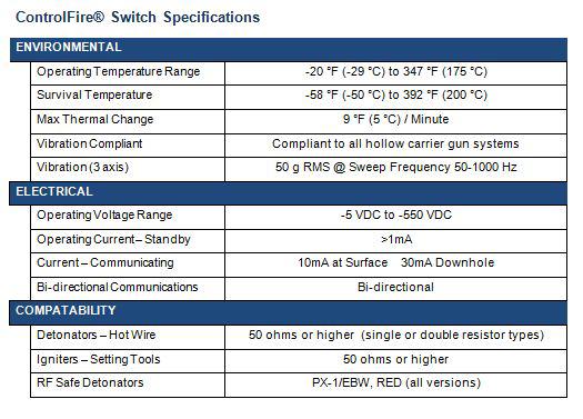
18 ControlFire Specifications
19 ControlFire Part Numbers Titan Part Numbers Description Part Number ControlFire Switch System ControlFire Switch v Command and Control Panel (portable) Command and Control Panel (rack mount) VeriFire Panel Wireline Switch Simulator Panel Panel External Test Block Cable Kit EBFire Feed Thru w/ Ground 9400-EBTW-WG EBFire Feed Thru 9400-EBTW Retainer Nut ¼ ID w/ Ground 9400-EBRN-WG Retainer Nut ¼ ID 9400-EBRN-250 RF-Safe ControlFire System (with Austin Powder detonator selection) RF-Safe Switch with A-85 Detonator DETO-CFA-A85-T RF-Safe Switch with A-96L Detonator DETO-CFA-A96L-T RF-Safe Switch with A-105 Detonator DETO-CFA-A105-T RF-Safe Switch with A Detonator DETO-CFA-A T RF-Safe Switch with A-140 Detonator DETO-CFA-A140-T RF-Safe Switch with A- 140F Detonator DETO-CFA-A140F-T RF-Safe Switch with A- 140S Detonator DETO-CFA-A140S-T Titan Shooting Power Supply ControlFire Shooting Power Supply
20 Contact Website Sales Houston, TX (281) Corporate Office Pampa, TX (806) Technical Support 24/7 6/10/
ControlFire. Titan Division Presentation
 ControlFire Titan Division Presentation Agenda Selective Switch History ControlFire Advanced Switch System Applications System Overview Safety Benefits and Features Developments Track Record Specifications
DynaSelect System. Plug-n-Perf Optimized
 DynaSelect System Plug-n-Perf Optimized PLUG-N-PERF MADE SAFER, MORE EFFICIENT AND MORE RELIABLE The DynaSelect System sets a new standard in dependable performance safety and operational cost savings
DEEP EXPERIENCE. STRONG REPUTATION.
 DEEP EXPERIENCE. STRONG REPUTATION. We know wireline and what it takes to earn trust in the industry. Our customers have come to count on our experience, technology and reliability. When you want better
REDEFINING PUMP DOWN PERFORATING
 REDEFINING PUMP DOWN PERFORATING 2018-NAPS-37 Authors: Sharif Aboelnaga, Pedro Hernandez, Carlos Eduardo Guedes, Fernando Garcia-Osuna, Schlumberger, Nick Snoke, FHE USA LLC AGENDA REDEFINING PUMP DOWN
GUIDE TO ASSEMBLY OF ERICA SYNTHS MIDI-CV MODULE
 GUIDE TO ASSEMBLY OF ERICA SYNTHS MIDI-CV MODULE If you are reading this, most probably, you are about to build Erica Synths DIY MIDI-CV module. This module is mm deep, skiff friendly, has solid mechanical
D115 The Fast Optimal Servo Amplifier For Brush, Brushless, Voice Coil Servo Motors
 D115 The Fast Optimal Servo Amplifier For Brush, Brushless, Voice Coil Servo Motors Ron Boe 5/15/2014 This user guide details the servo drives capabilities and physical interfaces. Users will be able to
output devices. connected to the controller. data communications link. relay systems. user program. MECH1500Quiz1ReviewVersion2 Name: Class: Date:
 Class: Date: MECH1500Quiz1ReviewVersion2 True/False Indicate whether the statement is true or false. 1. The number and type of I/Os cannot be changed in a fixed PLC. 2. In a PLC system, there is a physical
Product Datasheet. Touch screen Part number OPERATOR INTERFACE
 OPERATOR INTERFACE Application Main operating and indication panel for water based fire suppression systems. Each screen are designed for easy understanding without any nice to have function. The basic
ICSI Addressable Disconnect Tool (ADT) Overview
 Overview") ICSI Addressable Disconnect Tool (ADT) Overview Types of Disconnect Tools Offered From left to right: The first tool is the ADT Mod. CF. It is to be utilized when your gun system is comprised of Control
ICSI Addressable Disconnect Tool (ADT) Overview Types of Disconnect Tools Offered From left to right: The first tool is the ADT Mod. CF. It is to be utilized when your gun system is comprised of Control
I-Wheel Conveyance Technology Ultra-Flexible, Ultra-Reliable
 See how we can help you Please contact us to discuss your specific requirements: Technical Centers Fort Worth Technical Center, TX, USA 1132 Everman Parkway, #100 Forth Worth, TX 76140 T +1 817 568 8528
PT230 PONTOON THRUSTER INSTALLATION MANUAL (PATENT PENDING) VOLUME 1.2, JUNE 2015
 VOLUME 1.2, JUNE 2015") PT230 PONTOON THRUSTER (PATENT PENDING) INSTALLATION MANUAL VOLUME 1.2, JUNE 2015 Sideshift Inc. 130 Industrial Ave, Unit 303, Carleton Place, ON, Canada K7C 3T2 1.877.325.4787 +613.686.6011 INFO@SIDESHIFT.COM
PT230 PONTOON THRUSTER (PATENT PENDING) INSTALLATION MANUAL VOLUME 1.2, JUNE 2015 Sideshift Inc. 130 Industrial Ave, Unit 303, Carleton Place, ON, Canada K7C 3T2 1.877.325.4787 +613.686.6011 INFO@SIDESHIFT.COM
CA-A480-A Elevator Controller. Reference & Installation Manual
 CA-A480-A Elevator Controller Reference & Installation Manual TABLE OF CONTENTS INTRODUCTION.................................................................. 4 Introduction.............................................................................................
DET-TRONICS. INSTRUCTIONS Eagle Quantum Heart Beat Monitor EQ2400HBM Eagle 2000 Heart Beat Monitor EA2400HBM /99
 INSTRUCTIONS Eagle Quantum Heart Beat Monitor EQ2400HBM Eagle 2000 Heart Beat Monitor EA2400HBM INSTRUCTIONS Heart Beat Monitor EQ2400HBM & EA2400HBM Section I General Information The EA2400HBM and EQ2400HBM
PS/IO Circuit Board Retrofit
 S&C 6800 Series Automatic Switch Controls PS/IO Circuit Board Retrofit Table of Contents Section Page Introduction Qualified Persons.... 2 Read this Instruction Sheet.... 2 Retain this Instruction Sheet....
MODEL NC105 DIGITAL CODED SQUELCH ENCODER/DECODER INSTRUCTION MANUAL
 15385 Carrie Drive Grass Valley, CA 95959 Office: (530) 477-8400 Tech. Support: (530) 477-8402 FAX: (530) 477-8403 Sales: (800) 874-8663 Email: tech@norcommcorp.com Web: www.norcommcorp.com MODEL NC105
INSTALLATION MANUAL SLI 50 INVERTER
 INSTALLATION MANUAL SLI 50 INVERTER www.unipowerco.com Manual No. SLI-50-48-3 2016 UNIPOWER LLC All Rights Reserved UNIPOWER LLC 3900 Coral Ridge Drive, Coral Springs, Florida 33065, USA sales@unipowerco.com
MODEL NC400 MULTI-FUNCTION TOUCH-TONE DECODER INSTRUCTION MANUAL
 15385 Carrie Drive Grass Valley, CA 95959 Office: (530) 477-8400 Tech. Support: (530) 477-8402 FAX: (530) 477-8403 Sales: (800) 874-8663 Email: tech@ norcommcorp.com Web: www.norcommcorp.com MODEL NC400
Assembly Instructions CT-E Screen Read Board
 Assembly Instructions CT-E Screen Read Board If you ever need to use your CT-1024 terminal system in a situation where you need to get edited information that has been typed onto the screen, transmitted
SMM501/501-H (Surveillance Mode Module) Ford Police Interceptors (Sedan and SUV)
 Ford Police Interceptors (Sedan and SUV)") An ISO 9001:2008 Registered Company SMM501/501-H (Surveillance Mode Module) 2013-2014 Ford Police Interceptors (Sedan and SUV) Introduction The SMM501/501-H is intended for 2013 and 2014 Ford Police Interceptors
An ISO 9001:2008 Registered Company SMM501/501-H (Surveillance Mode Module) 2013-2014 Ford Police Interceptors (Sedan and SUV) Introduction The SMM501/501-H is intended for 2013 and 2014 Ford Police Interceptors
RS-485 Fiber-Optic Link RS-485 to Multi-Mode Fiber-Optic converter ST Fiber Connectors DIN Rail Mount
 Fiber-Optic Link to Multi-Mode Fiber-Optic converter ST Fiber Connectors DIN Rail Mount 101-0079 Installation Operation & Specifications Manual Auto-direcon control Supports BAUD rates up to 115,200 Fiber
Adapter Kit - Remote QSI Electronics Installation Instructions
 Adapter Kit Remote QSI Electronics Installation Instructions These installation instructions cover the adapter kit installation of the QSI1, QSI2 and QSI3 versions of communications electronics. The instructions
ADA User manual ADA RS-485 / RS-422 to RS-232 Converter. 1 io_ada-4010_v3.22_en. Copyright CEL-MAR sp.j.
 User manual ADA-4010 RS-485 / RS-422 to RS-232 Converter Copyright 2001-2017 CEL-MAR spj 1 io_ada-4010_v322_en Contents 1 GENERAL INFORMATION 3 11 WARRANTED INFORMATION 3 12 GENERAL CONDITIONS FOR SAFE
S Contents. Figure 1. Kyle Form 4C Analog Current Metering Accessory KME
 Reclosers Form 4C Microprocessor-Based Recloser Control Analog Current Metering Accessory KME4-82-1, KME4-82-2 Installation and Operation Instructions Service Information S280-77-8 Figure 1. Kyle Form
Fiber optic converter audio and CAN TA OPERATION MANUAL
 Fiber optic converter audio and CAN TA-110.1 IOA110-1 March 2009 LANEX S.A., Technical support: tel. ul.ceramiczna 8, 20-150 Lublin tel. +48 81 443 96 36 Contents 1. General Characteristics.... 5 1.1.
Instruction Sheet Board Style Low Water Cutoff
 Instruction Sheet Board Style Low Water Cutoff 102-305 SUPERSEDES: REVISION E DATED December 12, 2007 #5401173-REV F PLANT ID 001-3902 US Patents 6,904,800, 7,243,540, and 7,317,993 Other Patents Pending
* * Agilent Power Distribution Unit (PDU) Installation Guide
 Installation Guide") Agilent Power Distribution Unit (PDU) Installation Guide For use with Agilent PDU kits and PDU installation kits for Agilent instrument racks June 2008 Edition 7 E0608 *5000-0039* 5000-0039 Notice The
Agilent Power Distribution Unit (PDU) Installation Guide For use with Agilent PDU kits and PDU installation kits for Agilent instrument racks June 2008 Edition 7 E0608 *5000-0039* 5000-0039 Notice The
P9 ASD Simple Start Guide
 P9 ASD Simple Start Guide Document Number: 64056-002 Date: June, 2011 P9 ASD Simple Start Guide P9 Programming Using the EOI The operating parameters displayed on the LCD screen may be selected, viewed,
Propeller Project Board USB (#32810)
") Web Site: www.parallax.com Forums: forums.parallax.com Sales: sales@parallax.com Technical: support@parallax.com Office: (916) 624-8333 Fax: (916) 624-8003 Sales: (888) 512-1024 Tech Support: (888) 997-8267
Web Site: www.parallax.com Forums: forums.parallax.com Sales: sales@parallax.com Technical: support@parallax.com Office: (916) 624-8333 Fax: (916) 624-8003 Sales: (888) 512-1024 Tech Support: (888) 997-8267
Intelligent Solar Charge Controller User s Manual. Please read this manual carefully before you use this product
 Intelligent Solar Charge Controller User s Manual Please read this manual carefully before you use this product Contents 1. Product Introduction... 1 2. Installation... 2 3. Operation... 3 4. Common Fault
The Programmable 4-Way Relay Card is an optional peripheral unit that provides four individually programmable relay output circuits.
 Peripheral Relay The Programmable 4-Way Relay Card is an optional peripheral unit that provides four individually programmable relay output circuits. Up to 16 Cards can be connected to a multi-loop panel
Butterfly Laser Diode Mount
 LM14S2 Butterfly Laser Diode Mount Operating Manual LM14S2 Laser On TEC Driver LD Driver THORLABS, Inc. Ph: (973) 579-7227 435 Route 206N Fax: (973) 383-8406 Newton, NJ 07860 USA www.thorlabs.com 10614-D02
INSTALLATION INSTRUCTIONS
 TT-40 9/0 INSTALLATION INSTRUCTIONS Original Issue Date: 9/0 Model: Automatic Transfer Switches Equipped with the Programmable Controller Market: ATS Subject: External Battery Supply Module Kit GM69-KP
SGD 24-M-IP Waterproof PanelPilot-Compatible Smart Graphics Display
 Features 2.4 colour TFT screen IP-67 and NEMA 6 rated Rugged and scratch resistant Corning Gorilla Glass window Supplied with free Windows design software, to setup and customise the display. Compatible
Digital Flame 1.0 Kit
 Digital Flame 1.0 Kit Instruction Manual Eastern Voltage Research, LLC June 2012, Rev 1 1 http://www.easternvoltageresearch.com Introduction to the Digital Flame 1.0 Kit Thank you for purchasing the Digital
Long Gun Deployment Systems. Jim Gilliat BakerHughes Houston Texas Presentation Number: SLAP 06
 Long Gun Deployment Systems Jim Gilliat BakerHughes Houston Texas Presentation Number: SLAP 06 Wireline Deployment Risk Management Reduce Risk Pre-job planning highlights operational risk Risk mitigation
Instruction Manual. M Pump Motor Controller. For file reference, please record the following data:
 Instruction Manual M Pump Motor Controller For file reference, please record the following data: Model No: Serial No: Installation Date: Installation Location: When ordering replacement parts for your
4 Channel 4~20mA/0~10VDC Analog Data Fiber Link System
 USER GUIDE RLH Industries, Inc. The leader in rugged fiber optic technology. U-022 2017A-0330 4 Channel 4~20mA/0~10VDC Analog Data Fiber Link System SYSTEM INSTALLATION INFORMATION Description The 4 Channel
RMB Peripheral Units Installation Guide
 RMB Peripheral Units Installation Guide Part Number 65-000101 2011 by Kentrox, Inc. All rights reserved. Copyright 2011 by Kentrox, Inc. All Rights Reserved. The material discussed in this publication
1/32-DIN TEMPERATURE CONTROLLER INSTALLATION, WIRING AND OPERATION MANUAL FORM 3882
 1/32-DIN TEMPERATURE CONTROLLER INSTALLATION, WIRING AND OPERATION MANUAL FORM 3882 This manual is intended for use in support of installation, commissioning and configuration of the 1/32-DIN Temperature
R147 WIRELESS ANTI-TWO-BLOCK INDICATOR
 55M0147GSE00 Rev. E R147 WIRELESS ANTI-TWO-BLOCK INDICATOR Installation and Operation Manual Ref: VH sept 2012 Copyright 2012 RaycoWylie Systems All Rights Reserved. The purpose of this manual is to
Basketball Shot Clock Set LX2180 Manual
 Basketball Shot Clock Set LX2180 Manual 72 Industrial Boulevard Wrightsville, GA 31096 Phone: (800) 445-7843 Fax: (800) 864-0212 www.electro-mech.com LX2180 Revision 5 February 8, 2013 Table of Contents
MAXIMA + Series ROTARY LEVEL CONTROL
 Price $5.00 MAXIMA + Series ROTARY LEVEL CONTROL OPERATING INSTRUCTIONS PLEASE READ CAREFULLY Division of Garner Industries 7201 North 98th Street Lincoln, NE 68507-9741 (402) 434-9102 925-0268 TABLE OF
DTMF-4HC. DTMF decoder board with four high current relays. Copyright 2004 Intuitive Circuits, LLC
 DTMF-4HC DTMF decoder board with four high current relays Copyright 2004 Intuitive Circuits, LLC D escription DTMF-4HC is an inexpensive, self contained, DTMF (dual tone multiple frequency) decoder board
Digital Candle 1.0 Kit
 Kit Instruction Manual Eastern Voltage Research, LLC June 2012, Rev 1 1 http://www.easternvoltageresearch.com Introduction to the Kit Thank you for purchasing the Kit. This kit is definitely a favorite
MC 11 EB-2 Power supply cabinet with external bus, AC version
 MC 11 EB-2 Power supply cabinet with external bus, AC version USER/MAINTENANCE MANUAL 1 SLOT 0 SLOT 1 SLOT 2 SLOT 3 SLOT 4 SLOT 5 SLOT 6 SLOT 7 SLOT 8 SLOT 9 SLOT 10 SLOT 11 EB-2 (a) MC11 (b) (c) Figures
Instruction Manual. Electrical Management System (EMS) EMS-HW30C & EMS-HW50C
 EMS-HW30C & EMS-HW50C") Instruction Manual Electrical Management System (EMS) EMS-HW30C & EMS-HW50C EMS-HW50C EMS-HW30C! CAUTION These instructions are intended to provide assistance with the installation of this product, and
Instruction Manual Electrical Management System (EMS) EMS-HW30C & EMS-HW50C EMS-HW50C EMS-HW30C! CAUTION These instructions are intended to provide assistance with the installation of this product, and
This Datasheet for the IC670MDL VDC Pos/Neg Logic Input 16 Pt. Grouped.
 This Datasheet for the IC670MDL64 48VDC Pos/Neg Logic Pt. Grouped http://www.qualitrol.com/shop/p-46-ic670mdl64.aspx Provides the wiring diagrams and installation guidelines for this GE Field Control module.
SYSTEM 8 Advanced Test Module
 Board Tests in Production Maintenance & Repair Functional In-Circuit Testing Functional Board Level Testing SYSTEM 8 Advanced Test Module The Advanced Test Module (ATM) is a solution that offers high test
SPECIAL INSTRUCTIONS FOR CAPACITORS COMPACT GENERATORS
 SPECIAL INSTRUCTIONS FOR CAPACITORS COMPACT GENERATORS (WITH CAPACITOR CHARGER BOARD A3517-02) The process depends on Generator and System configuration. This document applies to installation of Capacitors
BA505C 2-wire 4/20mA manual setpoint station Issue 6
 BA505C 2-wire 4/20mA manual setpoint station Issue 6 Issue: 6 3 rd December 2010 2 CONTENTS 1. Description 2. Operation 3. Electrical Systems Design 3.1 4/20mA loop 3.2 Optional Backlights 3.2.1 Separately
Bluetooth Keyless Entry System - Lite
 Bluetooth Keyless Entry System - Lite Installation and operation manual DISCLAIMER: To aid users during the installation process, WE STRONGLY RECOMMEND THAT THIS MANUAL IS READ FIRST before beginning the
INSTALLATION GUIDE NP800R
 INSTALLATION GUIDE ICE - 11, rue Marcel Sembat - 94146 ALFORTVILLE CEDEX - France TEL. : (33) 01 41 79 76 00 - FAX : (33) 01 41 79 76 01 E-MAIL : contact@icelec.com SITE WEB : www.groupeice.com File: A662A
EA500. Installation Instructions Transponder
 EA500 EN Installation Instructions Transponder EA500 Installation Instructions 1.0 Overview EN 2 1.0 Overview The EA500 Transponder is the Security Escort module that provides communications between the
Operating manual. Series 450. Compact thermometer. BA01235O/09/en/
 Operating manual Series 450 Compact thermometer BA01235O/09/en/01.13 71220279 2 Table of contents 1 Safety instructions... 3 2 Installation... 4 3 Wiring overview... 7 4 Commissioning... 7 5 Operation...
S Reclosers Kyle Type VXE Electronic Control SCADA Input/Output Board Installation and Operation Instructions
 Reclosers Kyle Type VXE Electronic Control SCADA Input/Output Board Installation and Operation Instructions Cooper Power Systems Service Information S0-6- Applicable to VXE5 reclosers serial number 006
MicroLink Installation Operation & Specifications Manual. General Description
 TM MicroLink HART Protocol Modem - USB Interface 101-0007 Installation Operation & Specifications Manual General Description The MicroLink 101-0007 is a USB to HART device Interface. It provides the hardware
OMNITERM LPI & LPD Loop Powered Isolators DATASHEET. Model C2063B LPI (single) & C2462A LPD (dual) 4-20mA Loop Powered Isolators.
 & C2462A LPD (dual) 4-20mA Loop Powered Isolators.") Model C0B (single) & CA LPD (dual) 0mA Loop Powered Isolators Features Isolate any instrument current loop to 0ac Powered by the current loop no power supply required Lowest volt drop < Volts at 0 ma (,V
Model C0B (single) & CA LPD (dual) 0mA Loop Powered Isolators Features Isolate any instrument current loop to 0ac Powered by the current loop no power supply required Lowest volt drop < Volts at 0 ma (,V
PWRguard PLUS Spring City Drive Waukesha, WI
 PWRguard PLUS www.westmountainradio.com 1020 Spring City Drive Waukesha, WI 53186 262-522-6503 sales@westmountainradio.com 2016, All rights reserved. All trademarks are the property of their respective
CHAPTER 3B: ELECTRONIC POWER STEERING
 Electronic Power Steering CHAPTER 3B: ELECTRONIC POWER STEERING NOTE: The basic steering system, such as the tie rod ends, drag links axles, etc., is covered in Chapter 3A: Steering. In 2012, Cub Cadet
OPERATOR S MANUAL ATE 1/2 RACK POWER SUPPLY AUTOMATIC TEST EQUIPMENT MODEL
 OPERATOR S MANUAL ATE 1/2 RACK POWER SUPPLY AUTOMATIC TEST EQUIPMENT KEPCO INC. An ISO 9001 Company. MODEL 250W ATE 6-25, ATE 15-15, ATE 25-10, ATE 36-8, ATE 55-5, ATE 75-3, ATE 100-2.5, ATE 150-1.5, ATE
Application Note: AN0103. On-Board SPI programming with DediProg tools: Designer version
 4F., No.7, Ln. 143, Xinming Rd., Neihu Dist., Taipei City 114, Taiwan Application Note: AN0103 On-Board SPI programming with DediProg tools: Designer version DediProg Page 1/25 December 09 Table of content:
Instruction book IQAN-LSL. Publ no HY /UK Edition 0301
 Instruction book IQAN-LSL Publ no HY17-8367/UK Edition 0301 Contents 1 Introduction......................................................2 2 Precautions.......................................................3
Compact Keypad. ins /02/2010. Exit button (push to make) 12V DC release current rating must be less than 1A.
 12V DC release current rating must be less than 1A.") Compact Keypad Grey Exit button (push to make) 1V DC White Black 115V DC (fuse rating 1A) 1V DC release current rating must be less than 1A. The diode current rating must be equal to or greater than the
Compact Keypad Grey Exit button (push to make) 1V DC White Black 115V DC (fuse rating 1A) 1V DC release current rating must be less than 1A. The diode current rating must be equal to or greater than the
PowerFlex 755 Common DC Input Drives, Frames Interlock Assembly and Precharge Assembly Left-front Cover Retrofit Kit
 Installation Instructions PowerFlex 755 Common DC Input Drives, Frames 8...10 Interlock Assembly and Precharge Assembly Left-front Cover Retrofit Kit Catalog Numbers 20G14x, 21G14x Topic Page General Precautions
USER S MANUAL VER.1. C10D- PARALLEL PORT INTERFACE CARD BOARD Rev. 1
 USER S MANUAL VER.1 C10D- PARALLEL PORT INTERFACE CARD BOARD Rev. 1 MARCH 2018 User s Manual Page i USER'S MANUAL TABLE OF CONTENTS Contents Page # 1.0 OVERVIEW... iii 2.0 FEATURES... iii 3.0 SPECIFICATIONS...
XDBKITS5 Bus / DB Terminal Kit (Size 5) Installation Manual DPD00116
 Installation Manual DPD00116") XDBKITS5 Bus / DB Terminal Kit (Size 5) Installation Manual DPD00116 XDBKITS5 Option Kit Installation Manual vacon 3 Installing the Bus / DB Terminal Option Kit Introduction The XDBKITS5 option kit is
XDBKITS5 Bus / DB Terminal Kit (Size 5) Installation Manual DPD00116 XDBKITS5 Option Kit Installation Manual vacon 3 Installing the Bus / DB Terminal Option Kit Introduction The XDBKITS5 option kit is
DATRAN XL4 PLUS RTU Quick Start Guide
 DOC-QSG-XL4-PLUS-RTU DATRAN XL4 PLUS RTU Quick Start Guide Configuring the XL4 Plus RTU The XL4 Plus RTU is configured using software called QTech Workbench. Connection to your PC is via a USB cable (Type
ELECTRICAL SUPPLY TROUBLESHOOTING QUICK GUIDE SAFETY PRECAUTIONS
 ELECTRICAL SUPPLY TROUBLESHOOTING QUICK GUIDE 1. Circuit Breaker Tripping 2. Circuit Overload 3. Short Circuit 4. Ground Fault 5. Ground Fault Circuit Interrupter (GFCI) Tripping SAFETY PRECAUTIONS Basic
Installation Instructions
 Installation Instructions Cat. No. 1771-OND Series B This document provides information on: important pre-installation considerations power supply requirements installing the module setting the fault mode
4100/ VDC Converter Installation Instructions
 4100/4120-0156 8 VDC Converter Installation Instructions Introduction This publication describes the installation procedure for the 8 VDC Converter. Related Documentation Field Wiring Diagram for 4100
Installation and user manual English Français Deutsch Italiano Español Nederlands Pulsar Series
 www.eaton.com Evolution S 1250 RT 2U S 1750 RT 2U 2000 RT 2U S 2500 RT 2U S 3000 RT 2U S 3000 RT 3U S EXB 1250/1750 RT 2U S EXB 2500/3000 RT 2U S EXB 2500/3000 RT 3U Installation and user manual English
32-Channel Analogue Input Module Differential Input
 MAI32*AD 32-Channel Analogue Input Module Differential Input (MAI32*AD) Issue 4 October 2005 INTRODUCTION PURPOSE The Analogue Input Module provides up to 32, low voltage or current analogue input signals.
Parts List: Part # Tools List: Instructions:
 Parts List: Part # 1 pair of Dayton Audio B652s 300-652 1 Dayton Audio DTA-2 amplifier 300-385 1 MP3 module 320-350 1 7805 +5 VDC voltage regulator 7805 1 12 VDC 2A power supply 129-077 1 2.1 mm panel
Ordering information. Options:
 Numerical Control The CybTouch 12 PS and its revolutionary 12 inch Touch Screen interface enable it to use it with ease. Its intuitive graphic profile Touch drawing makes the CybTouch 12 PS a powerful,
Instruction book IQAN-LST. Publ no HY /UK Edition 0301
 Instruction book IQAN-LST Publ no HY17-8364/UK Edition 0301 Contents 1 Introduction......................................................2 2 Precautions.......................................................3
EFE300 / EFE400 EFE300M / EFE400M
 EFE300 / EFE400 EFE300M / EFE400M AC/DC Power Supply Series APPLICATION NOTE 68892 EFE300_400 App note 3.doc Document Number 68892 Page 1 of 11 1. INPUT... 3 AC INPUT LINE REQUIREMENTS... 3 2. DC OUTPUT...
Operation Manual Profibus DP -Display HE 5120 P with digital I/O's
 Operation Manual Profibus DP -Display HE 510 P with digital I/O's "HESCH" Schröder GmbH Boschstraße 8 31535 Neustadt Telefon +49 (0) 503 / 9535-0 Telefax +49 (0) 503 / 9535-99 e-mail: info@hesch.de http://www.hesch.de
SECTION N -- ELECTROSTATIC DISCHARGE (ESD)
") INSTALLATION REQUIREMENTS AT&T January, 2012 Section N, ATT-TP-76300 Revised NA SECTION N -- ELECTROSTATIC DISCHARGE (ESD) CONTENTS PAGE 1. GENERAL... N-1 1.1. Introduction... N-1 1.2. General Requirements...
INSTALLATION REQUIREMENTS AT&T January, 2012 Section N, ATT-TP-76300 Revised NA SECTION N -- ELECTROSTATIC DISCHARGE (ESD) CONTENTS PAGE 1. GENERAL... N-1 1.1. Introduction... N-1 1.2. General Requirements...
Universal Keying Adapter 3+
 Universal Keying Adapter 3+ The Universal Keying Adapter Version 3+ kit will allow you to key nearly any transmitter or transceiver with a straight key, electronic keyer, computer serial or parallel port
Hi-Tech Transport Electronics, Inc. DUAL LEVELING VALVE PROCESSOR INSTALLATION MANUAL. For the 4600 Scale System For the 5600 Scale System
 Hi-Tech Transport Electronics, Inc. DUAL LEVELING VALVE PROCESSOR INSTALLATION MANUAL For the 4600 Scale System For the 5600 Scale System September 1999 THE ACCURATE ON-BOARD ELECTRONIC SCALE For Air-Ride
MSR 2400R. Rugged Power System for Military and Heavy Duty Applications
 MSR 2400R Rugged Power System for Military and Heavy Duty Applications 2400 W modular power system Power supply or battery charging systems Parallel n+1 connection, up to 90A Series connection, up to 360VDC
CAN bus switch panels mounted either on the dash or the steering wheel allow for vastly simplified wiring and reduced weight.
 POWER MANAGEMENT UNIT PMU-16 PMU-16 Decades ago, the critical electronic components in a race car were the ignition coil and points. Race cars are now sophisticated machines equipped with advanced engine
Overview of the Cisco Wireless Gateway for LoRaWAN
 Overview of the Cisco Wireless Gateway for LoRaWAN This chapter provides an overview of the Cisco Wireless Gateway for LoRaWAN and contains the following sections: About Cisco Wireless Gateway for LoRaWANs,
Controllers for compressor racks with advanced energy saving. PN08 September 2016
 page 1 / 16 XC400/600 for small/medium compressor rack management Dixell introduces the new compact parametric controllers for compressor rack with. Dixell presents the XC400/600 series, dedicated to the
CDD Carbon Dioxide Transmitter
 Introduction The OSA CO2 transmitter uses Infrared Technology to monitor CO2 levels within a range of 0 2000 ppm and outputs a linear 4-20 ma or 0-5/0-10 Vdc signal. The enclosure is designed to operate
DS5000-IBFS. 5kA rms - 8kA DC Fluxgate current transducer. Features. Description. Application. Precision Innovation /
 5kA rms - 8kA DC Fluxgate current transducer Features DC 8000A AC 5000A rms Maximum gain error DC to 1kHz - 0.1% Transducer core optimized for high level of immunity against external magnetic fields Operating
Advanced Strobe 1.0 Kit
 Kit Instruction Manual Eastern Voltage Research, LLC December 2013, Rev 1 1 http://www.easternvoltageresearch.com Kit Introduction to the Kit Thank you for purchasing the Kit. If you are looking for a
Product Data Sheet. BMS/Graphics Interface. Features
 BMS/Graphics Interface Product Data Sheet Features The Mxp-010 interface allows BMS systems and graphics PCs to be integrated with the Mx- 4000 series of Fire Control Panels and Remote Terminals. The interface
Nevco Message Center Installation Manual Retain this manual in your permanent file. 08/27/ Rev. C
 Nevco Message Center Installation Manual Retain this manual in your permanent file. 08/27/2014 135-0144 Rev. C Table of Contents INSTALLATION INSTRUCTIONS... 1 UNPACKING THE EQUIPMENT... 1 MESSAGE CENTER
Evolution 650/650 Rack 1U 850/850 Rack 1U 1150/1150 Rack 1U 1550/1550 Rack 1U Installation and user manual Pulsar Series
 www.eaton.com _ Evolution 650/650 Rack 1U 850/850 Rack 1U 1150/1150 Rack 1U 1550/1550 Rack 1U Installation and user manual Pulsar Series 34008235EN/AC - Page 2 Introduction Thank you for selecting an EATON
SE-135 MANUAL GROUND-FAULT GROUND-CHECK MONITOR
 SE-135 MANUAL GROUND-FAULT GROUND-CHECK MONITOR AUGUST 14, 2001 REVISION 1 Publication: SE-135-M Document: S95-C135-00000 Printed in Canada. Copyright 2001 by Startco Engineering Ltd. All rights reserved.
SQ405 Controller CAUTION. The caution messages are displayed before procedures which, if not followed, could cause damage to the equipment.
 87-900-112-01 (A) April 18th, 2011 INSTRUCTIONS SQ405 Controller GENERAL INFORMATION This equipment is destined for use by professionals. The user should read this instruction manual and any other additional
Installation manual CF8-W-Disp-AL
 Installation manual CF8-W-Disp-AL CO 2 transmitter with two relays mounted in industrial housing prepared for Modbus communication protocol 4 7 8 8 6 3 2 5 Wall plate 5 Snap-in lid 2 PCB (Factory supplied
This Datasheet for the IC670MDL VDC Pos/Neg Logic Input 16 Pt. Grouped.
 This Datasheet for the IC670MDL640 24VDC Pos/Neg Logic Input 6 Pt. Grouped http://www.cimtecautomation.com/parts/p-4-ic670mdl640.aspx Provides the wiring diagrams and installation guidelines for this GE
Circuit Breaker Sentinel (CBS) for SF 6. power circuit breakers
 for SF 6. power circuit breakers") Circuit Breaker Sentinel (CBS) for SF 6 power circuit breakers Circuit Breaker Sentinel (CBS) for SF 6 power circuit breakers It is widely recognized that the concept of periodic equipment maintenance
Circuit Breaker Sentinel (CBS) for SF 6 power circuit breakers Circuit Breaker Sentinel (CBS) for SF 6 power circuit breakers It is widely recognized that the concept of periodic equipment maintenance
4-20mA SERIES Single or Dual Axis MEMS Inclinometer
 4-20mA SERIES Single or Dual Axis MEMS Inclinometer The 2GIG 4-20mA Inclinometer is engineered to work for all applications. The internal software provides unlimited programming capabilities. It offers
Features. Line Regulation. Load Regulation. Safety. Cooling. Input Connectors. Output Connectors. Overvoltage Protection. Over Temperature Protection
 Specifications: Input Voltage ( 3 phase ) No of Phases Input Frequency 208VAC ( 170 ~ 265 ) Code: 3P208 415VAC ( 342 ~ 460 ) Code: 3P400 Wye or Delta, 4 wire 3phase and one protective earth. 47 ~ 63Hz
Operating Instructions (compact) SIMATIC. Industrial PC SIMATIC Panel PC 577. Release 04/2006 A5E
 SIMATIC. Industrial PC SIMATIC Panel PC 577. Release 04/2006 A5E") Operating Instructions (compact) 1 SIMATIC Industrial PC Release 04/2006 A5E00795255 Safety Guidelines This manual contains notices you have to observe in order to ensure your personal safety, as well
Operating Instructions (compact) 1 SIMATIC Industrial PC Release 04/2006 A5E00795255 Safety Guidelines This manual contains notices you have to observe in order to ensure your personal safety, as well
PRODUCT OVERVIEW. Well Inspection Cameras & Systems. See what you re missing. Proudly made in the U.S.A.
 PRODUCT OVERVIEW Well Inspection Cameras & Systems See what you re missing. Proudly made in the U.S.A. See what you re missing. Aries provides the equipment you need for efficient well inspection to ensure
EFE300 / EFE400 EFE300M / EFE400M
 EFE300 / EFE400 EFE300M / EFE400M AC/DC Power Supply Series APPLICATION NOTE 68892 EFE300_400 App note 8.doc Document Number 68892 Page 1 of 13 1. INPUT... 3 AC INPUT LINE REQUIREMENTS... 3 2. DC OUTPUT...