Pamoco SpA - via Riccardo Lombardi 19/ Milano - tel fax
|
|
|
- Leona Shields
- 5 years ago
- Views:
Transcription
1 By detecting motor voltage, current, and back-emf Precision current control technology Most stepper systems resonate at mid-range speed signal, Leadshine digital drives can detect loss-ofsynchronization of stepper motors without encoders. reduce about 70% motor noise, natural frequency of the stepper system and apply and multi-stepping technology can between 10 to 18 rps. DM stepper drives can calculate The sensorless stall detection eliminates cost of making the DM series to be an ideal damping in control algorithm for anti-resonance, Providing feedback devices and time of cable connection. solution for the applications require optimizing torque and nulling mid-range instability. Electronic damping for 3 major resonance frequencies for stepper motors at low speed range, eliminating undesirable motor speed oscillation and delivering unique level of smoothness. Multi-stepping allows a low resolution input to produce a higher microstep output for smoother system performance. This function can improve smoothness of the stepper systems without upgrading your motion controllers. Due to DSP precision current control algorithm, 0 motor heat is 10 0 C lower compare to a traditional stepper drive. Longer motor lifetime can be achieved, reducing maintenance cost. Drive heat is also 0% lower, offering higher drive stability and energy efficiency. Command signal smoothing can soften the effect of suddent changes in velocity and direction, thus delivering smoother performance and improving system liftime. Torque improvement increases torque up to 30% at high speed, therefore they can drive a normal stepper motor to 3000 RPM or even higher, and significantly increase production efficiency. Motor-self-test and parameter-auto-configuration technology offers optimum performance for different motors. It is easier for users to configure different axes or build different machines ON Turn SW4 times switch in 1 second.


2 By implementing the latest motion control technologies, Leadshine's DM series DSP-based stepper drives deliver excellent performance not available before. Unique features of super-low motor noise, extra smoothness and excellent high speed performance make DM stepper drives deliver servo-like performance at the cost of stepper drives. Leadshine DM series stepper drives are able to drive -phase or 3-phase stepper motors from NEMA8 to NEMA51. Leadshine DM stepper drives are suitable for driving a wide range of stepper motors, from NEMA frame size 8 to 4. Typical applications includ CNC routers, laser cutters, laser markers, medical equipments, X-Y tables, measurement equipments, etc. *This function is available on the AM88 and other EMxxx stepper drives. Visit Leadshine's website for the latest information about our digital stepper drives. ** Those of the DM30C and DM4C are 75 khz, and that of the DM44 is 00 khz.
 is for control signal connections, and connector type P is for power and motor connections.")


3 There are two connector types for a DM stepper drive. Connector type P1 (See figure below.) is for control signal connections, and connector type P is for power and motor connections. The RS3 communication port is for parameter configurations via computer. See brief descriptions for these connectors and interface below. When configuring an EM series stepper drive through DIP switches, use SW1,,3 to set output current, and SW5,6,7 to set mmicrostep resolutions. SW4 is for standstill current setting and motor self-test & auto-configuration function (Turn SW4 times switch in 1 second.). SW8 is for active edge setting of pulse signals. Tips: 1. Users are suggested to use motor self-test and auto-configuration function when powering up the system (with the motor) for the first time, or replacing a new motor.. To operate at current and microstep settings configured by software or STU, DIP switch must set to default mode. 3. Only software ProTuner can be used to configure anti-resonance parameter settings. 4. How many times the RED light blinks on in a periodic time indicates what protection has been activated. See manuals for detail. For most of applications, configurations set by self-test and auto-configuration function should be good enough to meet the application requirements. However, a user can also configure the advanced features such as anti-resonance and advanced current loop tuning through software or STU-DM, a simple device specially designed for easy tuning.


4 Upload and Download parameter settings PI parameter settings for current loop Microstep resolution and output current settings Operation mode configuration :PUL/DIR, CW/CCW, analog DIR logic level setting Active edge of pulse signal setting Electronic damping coefficient setting Anti-resonance parameter settings for 3 resonance area Parameter settings for self motion test or a simple application Read the latest 10 failure events and clear these events * 1 PC RS3 interface is necessary. ** Leadshine offers special cable for communication between ProTuner and the drive. Upload and Download parameter settings PI parameter settings for current loop Microstep resolution and output current settings Operation mode configuration :PUL/DIR, CW/CCW, analog DIR logic level setting Active edge of pulse signal setting Parameter settings for self motion test or a simple application * Leadshine offers special cable for communication between the STU-DM and the drive.
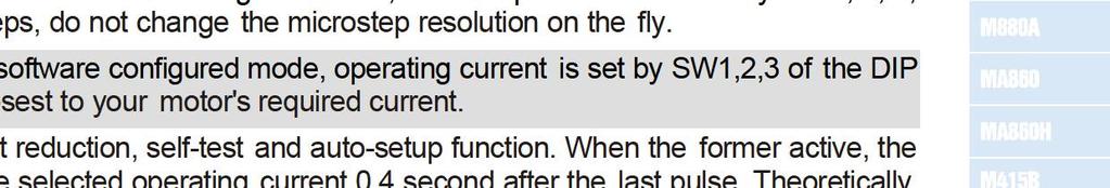
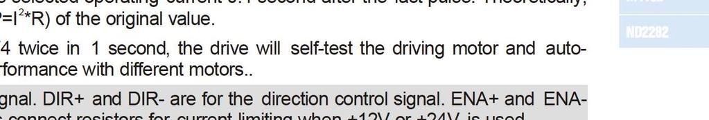
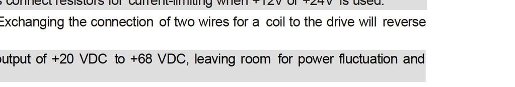
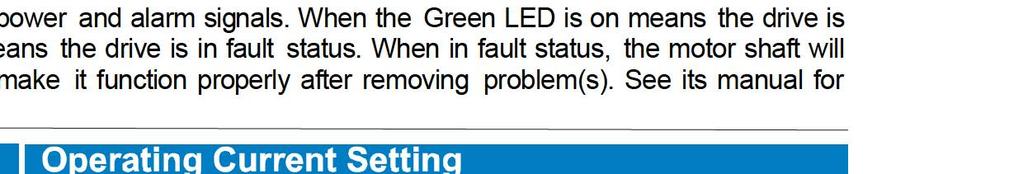
5 The DM30C is a versatility fully digital stepper drive based on a DSP with advanced control algorithm. It brings a unique level of system smoothness, providing optimum torque and nulls mid-range instability. Motor auto-identification and parameter auto-configuration technology offers optimum response with different motors. The driven motors can run with much lower noise, lower heating, smoother movement than most stepper drives on the market. Suitable for a wide range of stepper motors, from NEMA8 to NEMA3. It can be used in various kinds of machines, such as medical machines, laser cutters, laser markers, high precision X-Y tables, labelling machines, and so on. Its unique features make the DM30C an ideal solution for applications that require low-speed smoothness. Description Microstep resolution is programmable. When not in software configured mode, microstep resolution is set by SW5, 6 of the DIP switch. In order to avoid losing steps, do not change the microstep resolution on the fly. Output current is programmable. When not in software configured mode, operating current is set by SW1,,3 of the DIP switch. Up to.0 A. Select a current setting closest to your motor's required current. SW4 is used for the automatic standstill current reduction, self-test and auto-configuration functions. When the former active, the current will automatically reduced to 60% of the selected operating current 0.4 second after the last pulse. Theoretically, this will reduce motor heating to 36% (due to P=I *R) of the original value. PUL+ and PUL- are for the pulse command signal. DIR+ and DIR- are for the direction control signal. ENA+ and ENA- are for the enable/ disable control signal. ALM+ and ALM- are for the alarm signal. Series connect resistors for current-limiting when +1V or +4V is used. A+, A- and B+, B- are for motor connections. Exchanging the connection of two wires for a coil to the drive will reverse default motion direction. Recommended to use power supplies with output of +18 VDC to +4 VDC, leaving room for power fluctuation and There are two LED indicators on the drive for power and alarm signals. When the Green LED is on means the drive is powered up, and when the Red LED is on means the drive is in fault status. When in fault status, the motor shaft will be free. Reset the drive by re-powering it to make it function properly after removing problem(s). See its manual for more information. software configured mode, the drive uses a 6-bit DIP switch to set microstep resolution and motor operating current, as shown below: Operating Current Setting All ON is software configured Microstep Resolution Setting All ON is software configured
6 The DM4C is a versatility fully digital stepper drive based on a DSP with advanced control algorithm. It brings a unique level of system smoothness, providing optimum torque and nulls mid-range instability. Motor auto-identification and parameter auto-configuration technology offers optimum response with different motors. The driven motors can run with much lower noise, lower heating, smoother movement than most stepper drives on the market. Suitable for a wide range of stepper motors, from NEMA8 to NEMA3. It can be used in various kinds of machines, such as medical machines, laser cutters, laser markers, high precision X-Y tables, labelling machines, and so on. Its unique features make the DM4C an ideal solution for applications that require low-speed smoothness. Description Microstep resolution is programmable. When not in software configured mode, microstep resolution is set by SW5, 6 of the DIP switch. In order to avoid losing steps, do not change the microstep resolution on the fly. Output current is programmable. When not in software configured mode, operating current is set by SW1,,3 of the DIP switch. Up to.a. Select a current setting closest to your motor's required current. SW4 is used for the automatic standstill current reduction, self-test and auto-configuration function. When the former active, the current will automatically reduced to 60% of the selected operating current 0.4 second after the last pulse. Theoretically, this will reduce motor heating to 36% (due to P=I *R) of the original value. OPTO is for the opto-coupler power supply, typically+5v. PUL is for the pulse command signal. DIR is for the direction control signal. ENA is for the enable/ disable control signal. Series connect resistors for current-limiting when +1V or +4V is used. A+, A- and B+, B- are for motor connections. Exchanging the connection of two wires for a coil to the drive will reverse default motion direction. Recommended to use power supplies with output of +18 VDC to +36 VDC, leaving room for power fluctuation and There are two LED indicators on the drive for power and alarm signals. When the Green LED is on means the drive is powered up, and when the Red LED is on means the drive is in fault status. When in fault status, the motor shaft will be free. Reset the drive by re-powering it to make it function properly after removing problem(s). See its manual for more information. software configured mode, the drive uses a 6-bit DIP switch to set microstep resolution, and motor operating current, as shown below:
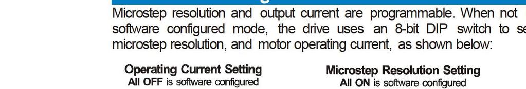
7 The DM44 is a versatility fully digital stepper drive based on a DSP with advanced control algorithm. It brings a unique level of system smoothness, providing optimum torque, nulls mid-range instability and good high speed performance. Motor auto-identification and parameter auto-configuration technology offers optimum response with different motors. The driven motors can run with much lower noise, lower heating, smoother movement than most stepper drives on the market. Suitable for a wide range of stepper motors, from NEMA10 to NEMA3. It can be used in various kinds of machines, such as medical machines, laser cutters, laser markers, high precision X-Y tables, labelling machines, and so on. Its unique features make the DM44 an ideal solution for applications that require low-speed smoothness and good high speed performance.. Microstep resolution is programmable. When not in software configured mode, microstep resolution is set by SW5, 6, 7, 8 of the DIP switch. In order to avoid losing steps, do not change the microstep resolution on the fly. Output current is programmable. When it's not in software configured mode, operating current is set by SW1,,3 of the DIP switch. Up to 4. A. Select a current setting closest to your motor's required current. SW4 is used for the automatic standstill current reduction, self-test and auto-configuration function. When the former active, the current will automatically reduced to 60% of the selected operating current 0.4 second after the last pulse. Theoretically, this will reduce motor heating to 36% (due to P=I *R) of the original value. PUL+ and PUL- are for the pulse command signal. DIR+ and DIR- are the for direction control signal. ENA+ and ENAare for the enable/ disable control signal. Series connect resistors for current-limiting when +1V or +4V is used. A+, A- and B+, B- are for motor connections. Exchanging the connection of two wires for a coil to the drive will reverse default motion direction. Recommended to use power supplies with output of +18 VDC to +36 VDC, leaving room for power fluctuation and There are two LED indicators on the drive for power and alarm signals. When the Green LED is on means the drive is powered up, and when the Red LED is on means the drive is in fault status. When in fault status, the motor shaft will be free. Reset the drive by re-powering it to make it function properly after removing problem(s). See its manual for more information. software configured mode, the drive uses an 8-bit DIP switch to set microstep resolution, and motor operating current, as shown below:
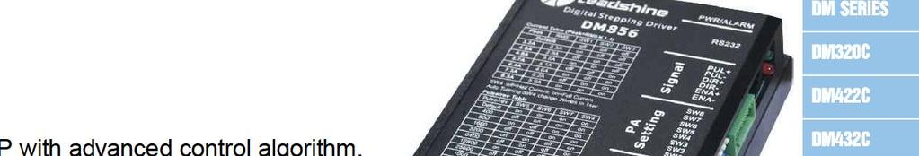
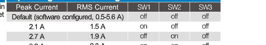
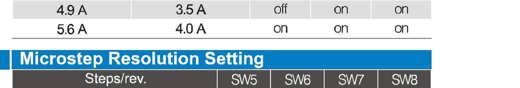
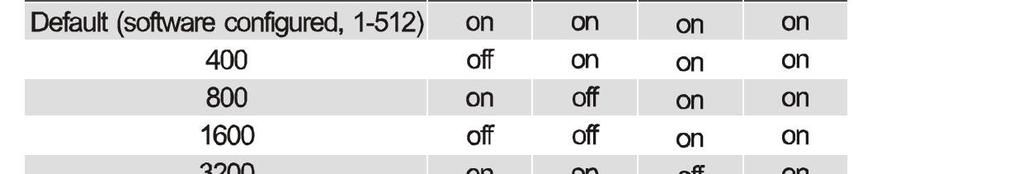
8 The DM556 is a versatility fully digital stepper drive based on a DSP with advanced control algorithm. It brings a unique level of system smoothness, providing optimum torque, nulls mid-range instability and good high speed performance. Motor auto-identification and parameter auto-configuration technology offers optimum response with different motors. The driven motors can run with much lower noise, lower heating, smoother movement than most stepper drives on the market. Suitable for a wide range of stepper motors, from NEMA17 to NEMA34. It can be used in various kinds of machines, such as medical machines, laser cutters, laser markers, high precision X-Y tables, labelling machines, and so on. Its unique features make the DM556 an ideal solution for applications that require low-speed smoothness and good high speed performance.. Microstep resolutions is programmable. When not in software configured mode, microstep resolution is set by SW5, 6, 7, 8 of the DIP switch. In order to avoid losing steps, do not change the microstep resolution on the fly. Output current is programmable. When it's not in software configured mode, operating current is set by SW1,,3 of the DIP switch. Up to 5.6 A. Select a current setting closest to your motor's required current. SW4 is used for the automatic standstill current reduction, self-test and auto-configuration function. When the former active, the current will automatically reduced to 60% of the selected operating current 0.4 second after the last pulse. Theoretically, this will reduce motor heating to 36% (due to P=I *R) of the original value. PUL+ and PUL- are for the pulse command signal. DIR+ and DIR- are for the direction control signal. ENA+ and ENAare for the enable/disable control signal. Series connect resistors for current-limiting when +1V or +4V is used. A+, A- and B+, B- are for motor connections. Exchanging the connection of two wires for a coil to the drive will reverse default motion direction. Recommended to use power supplies with output of +0 VDC to +45 VDC, leaving room for power fluctuation and There are two LED indicators on the drive for power and alarm signals. When the Green LED is on means the drive is powered up, and when the Red LED is on means the drive is in fault status. When in fault status, the motor shaft will be free. Reset the drive by re-powering it to make it function properly after removing problem(s). See its manual for more information. software configured mode, the drive uses an 8-bit DIP switch to set microstep resolution, and motor operating current, as shown below:


9 Pamoco SpA - via R.Lombardi 19/6, 0153 Milano - tel. (+39) fax (+39) web: info@pamoco.it
10 The DM870 is a versatility fully digital stepper drive based on a DSP with advanced control algorithm. It brings a unique level of system smoothness, providing optimum torque, nulls mid-range instability and good high speed performance. Motor auto-identification and parameter auto-configuration technology offers optimum response with different motors. The driven motors can run with much lower noise, lower heating, smoother movement than most stepper drives on the market. Suitable for a wide range of stepper motors, from NEMA17 to NEMA34. It can be used in various kinds of machines, such as medical machines, laser cutters, laser markers, high precision X-Y tables, labelling machines, and so on. Its unique features make the DM870 an ideal solution for applications that require low-speed smoothness and good high speed performance. Description Microstep resolution is programmable. When not in software configured mode, microstep resolution is set by SW5, 6, 7, 8 of the DIP switch. In order to avoid losing steps, do not change the microstep resolution on the fly. Output current is programmable. When not in software configured mode, operating current is set by SW1,,3 of the DIP switch. Up to 7.0 A. Select a current setting closest to your motor's required current. SW4 is used for the automatic standstill current reduction, self-test and auto-configuration function. When the former active, the current will automatically reduced to 60% of the selected operating current 0.4 second after the last pulse. Theoretically, this will reduce motor heating to 36% (due to P=I *R) of the original value. PUL+ and PUL- are for the pulse command signal. DIR+ and DIR- are for the direction control signal. ENA+ and ENAare for the enable/ disable control signal. Series connect resistors for current-limiting when +1V or +4V is used. A+, A- and B+, B- are for motor connections. Exchanging the connection of two wires for a coil to the drive will reverse default motion direction. Recommended to use power supplies with output of +0 VDC to +68 VDC, leaving room for power fluctuation and There are two LED indicators on the drive for power and alarm signals. When the Green LED is on means the drive is powered up, and when the Red LED is on means the drive is in fault status. When in fault status, the motor shaft will be free. Reset the drive by re-powering it to make it function properly after removing problem(s). See its manual for more information. software configured mode, the drive uses an 8-bit DIP switch to set microstep resolution, and motor operating current, as shown below:


11 The DM8 is a versatility fully digital stepper drive based on a DSP with advanced control algorithm. It brings a unique level of system smoothness, providing optimum torque, nulls mid-range instability and good high speed performance. Motor auto-identification and parameter autoconfiguration technology offers optimum response with different motors. The driven motors can run with much lower noise, lower heating, smoother movement than most stepper drives on the market. Suitable for a wide range of stepper motors, from NEMA34 to NEMA51. It can be used in various kinds of machines, such as medical machines, laser cutters, laser markers, high precision X-Y tables, labelling machines, and so on. Its unique features make the DM8 an ideal solution for applications that require low-speed smoothness and good high speed performance. Description Microstep resolution is programmable. When not in software configured mode, microstep resolution is set by SW5, 6, 7, 8 of the DIP switch. In order to avoid losing steps, do not change the microstep resolution on the fly. Output current is programmable. When not in software configured mode, operating current is set by SW1,,3 of the DIP switch. Up to 8. A. Select a current setting closest to your motor's required current. SW4 is used for the automatic standstill current reduction, self-test and auto-configuration function. When the former active, the current will automatically reduced to 60% of the selected operating current 0.4 second after the last pulse. Theoretically, this will reduce motor heating to 36% (due to P=I *R) of the original value. PUL+ and PUL- are for the pulse command signal. DIR+ and DIR- are for the direction control signal. ENA+ and ENAare for the enable/ disable control signal. Series connect resistors for current-limiting when +1V or +4V is used. A+, A- and B+, B- are for motor connections. Exchanging the connection of two wires for a coil to the drive will reverse default motion direction. Recommended to use power supplies with output of 90 VAC to 00 VAC, leaving room for power fluctuation and There are two LED indicators on the drive for power and alarm signals. When the Green LED is on means the drive is powered up, and when the Red LED is on means the drive is in fault status. When in fault status, the motor shaft will be free and fault out (OC) will be pulled to low. Reset the drive by re-powering it to make it function properly after removing problem(s). See its manual for more information. software configured mode, the drive uses an 8-bit DIP switch to set microstep resolution, and motor operating current, as shown below: Standstill Current (ON haft / OFF full) Self-test and Auto-configuration ( changes in 1 second)
EM705 2-phase Digital Stepper Drive
 EM705 2-phase Digital Stepper Drive 20-70V, 0.35-5A, Sensorless Stall Detection, Pre-Matching Motor Sensorless stall detection eliminates cost of feedback devices and time of cable connection Super-low
EM806 2-phase Digital Stepper Drive
 EM806 2-phase Digital Stepper Drive 24-80V, 0.35-6A, Sensorless Stall Detection, Pre-Matching Motor Sensorless stall detection eliminates cost of feedback devices and time of cable connection Super-low
FEATURES: DESCRIPTION: APPLICATIONS: SPECIFICATIONS: Electrical Specifications of Drive: Operating Environment: [Geben Sie Text ein]
![FEATURES: DESCRIPTION: APPLICATIONS: SPECIFICATIONS: Electrical Specifications of Drive: Operating Environment: [Geben Sie Text ein]](/thumbs/93/111844613.jpg "FEATURES: DESCRIPTION: APPLICATIONS: SPECIFICATIONS: Electrical Specifications of Drive: Operating Environment: [Geben Sie Text ein]") ist-09 ist-0 FEATURES: Integrated compact size for saving mounting space & setup time, and reducing electrical interference Anti-Resonance provides optimal torque and nulls mid-range instability Motor
ist-09 ist-0 FEATURES: Integrated compact size for saving mounting space & setup time, and reducing electrical interference Anti-Resonance provides optimal torque and nulls mid-range instability Motor
User Manual For DM332T. 2-Phase Digital Stepper Drive. Designed by StepperOnline. Manufactured by Leadshine
 User Manual For DM332T 2-Phase Digital Stepper Drive Designed by StepperOnline Manufactured by Leadshine #7 Zhongke Road, Jiangning, Nanjing, China T: 0086-2587156578 Web site: www.omc-stepperonline.com
User s Manual. Fully Digital Stepping Drive. For DM442. Version All Rights Reserved
 The content in this manual has been carefully prepared and is believed to be accurate, but no responsibility is assumed for inaccuracies. User s Manual For DM442 Fully Digital Stepping Drive Version 1.0
MSD325 Microstepping Drive
 MSD325 Microstepping Drive Introduction MSD325 is a very small size microstepping drive based on most advanced technology in the world today. It is suitable for driving any 2-phase and 4-phase hybrid stepper
User Manual of 3M583
 ECG-SAVEBASE EMAIL:EBAY@SAVEBASE.COM WEB: HTTP://STORES.EBAY.CO.UK/SAVEBASE User Manual of 3M583 High Performance Microstepping Driver ECG-SAVEBASE ECG Safety Statement Easy Commercial Global is not liable
KL-8056D. Table of Contents. Fully Digital Stepping Driver
 Contents KL-8056D Fully Digital Stepping Driver Attention: Please read this manual carefully before using the driver! Table of Contents 1. Introduction, Features and Applications...1 Introduction...1 Features...1
KL-4042D Fully Digital Stepping Drive
 KL-4042D Fully Digital Stepping Drive Version 1.0 2010 All Rights Reserved Attention: Please read this manual carefully before using the drive! Table of Contents 1. Introduction, Features and Applications...
User s Manual. Extremely Low Noise 3-phase Microstepping Driver. For 3L583M. Version All Rights Reserved
 User s Manual For Extremely Low Noise 3-phase Microstepping Driver Version 1.0 2008 All Rights Reserved Attention: Please read this manual carefully before using the driver! The content in this manual
ii Leadshine reserves the right to make changes without further notice to any products herein to improve reliability, function or design. Leadshine do
 Hardware Installation Manual for EM Series Stepper Drives www.leadshine.com ii Leadshine reserves the right to make changes without further notice to any products herein to improve reliability, function
Change Log by Leadshine Technology, All Rights Reserved
 Hardware Installation Manual for EM Series Stepper Drives www.leadshine.com NTS-HWMN-EM-R2011101 ii Leadshine reserves the right to make changes without further notice to any products herein to improve
Preliminary Datasheet MX Axis Stepper Drive with Breakout Board & I/O s. Preliminary V1.0
 Preliminary Datasheet MX4660 4-Axis Stepper Drive with Breakout Board & I/O s Preliminary V1.0 Features Power up to 4 stepper motors of NEMA 17, 23, 24, or 34 Sophisticated stepper motor control based
Hardware Installation Manual
 Hardware Installation Manual Of the Easy servo Drives Version 0.0.1 http://www.leadshine.com ii Safety Items! Notice Read this manual carefully before trying to install the stepper drive into your system.
Datasheet MX Axis Stepper Drive with Breakout Board & I/O s. Version
 Datasheet MX4660 4-Axis Stepper Drive with Breakout Board & I/O s Version 1.0 http://www.leadshine.com http://www.leadshineusa.com 2014 Leadshine Technology Co., Ltd. Notice This document is not for use
Hardware Installation Manual Integrated BLDC Servo Motor
 Hardware Installation Manual Integrated BLDC Servo Motor Version 1.0.0 http://www.leadshine.com Safety Items! Caution Make sure the power supply voltage dose not exceed the drive s input range. Double
Hardware Manual of Easy Servo Drives ES-D Series
 Hardware Manual of Easy Servo Drives ES-D Series Version 0.1.0 http://www.leadshine.com ii Safety Items! Notice Read this manual carefully before trying to install the stepper drive into your system. The
3-Axis Stepper Drive Datasheet MX3660
 3-Axis Stepper Drive Datasheet MX3660 3-Axis Stepper Drive + Breakout Board, 20-60VDC, 6A Peak Version 0.0.2 http://www.leadshine.com Features Three individual stepper drive boards Suitable for NEMA17
EM556S Digital Stepper Drive User Manual. User Manual EM556S. Digital Stepper Drive. Revision All Rights Reserved
 User Manual EM556S Digital Stepper Drive Revision 1.0 2017 All Rights Reserved Important Notice Read this manual carefully before any assembling and using. Incorrect handling of products in this manual
SDM / 4 Phase Stepper Drive Module. Compact Size & High Power Density, 20-60VDC, 6A Peak. Version 1.0
 SDM660 2 / 4 Phase Stepper Drive Module Compact Size & High Power Density, 20-60VDC, 6A Peak Version 1.0 http://www.leadshine.com / http://www.leadshineusa.com 2013 Leadshine Technology Co., Ltd. 3/F,
Datasheet MX Axis Stepper Drive with Breakout Board & I/O s. Version1.0
 Datasheet MX3660 3-Axis Stepper Drive with Breakout Board & I/O s Version1.0 1. Features Power up to 3 stepper motors of NEMA 17, 23, 24, or 34 Sophisticated stepper motor control based on latest DSP technology
Datasheet MX Axis Stepper Drive with Breakout Board & I/O s. Version
 Datasheet MX3660 3-Axis Stepper Drive with Breakout Board & I/O s Version 1.1 http://www.leadshine.com http://www.leadshineusa.com 2013 Leadshine Technology Co., Ltd. Notice This manual is not for use
MSD980 Microstepping Drive
 MSD980 Microstepping Drive Introduction MSD980 is a high-performance microstepping drive based on most advanced technology in the world today. It is suitable for driving any 2-phase and 4-phase hybrid
User Manual DM556T. 2 Phase Digital Stepper Drive. Designed by StepperOnline Manufactured by Leadshine 2017 All Rights Reserved
 User Manual DM556T 2 Phase Digital Stepper Drive Designed by StepperOnline Manufactured by Leadshine 2017 All Rights Reserved Address: #7 Zhongke Road, Jiangning, Nanjing, China Tel: 0086-2587156578 Web:
DM542E. User Manual. 2 Phase Digital Stepper Drive Leadshine Technology Co., Ltd. Revision 1.0
 User Manual DM542E 2 Phase Digital Stepper Drive Revision 1.0 2016 Leadshine Technology Co., Ltd. Leadshine Technology Co., Ltd (Headquarters) Address: Floor 11, Block A3, ipark 1001 Xueyuan Avenue Shenzhen,
AM882. User s Manual For. Fully Digital Stepping Drive. Version All Rights Reserved
 User s Manual For AM882 Fully Digital Stepping Drive Version 1.0 2010 All Rights Reserved Attention: Please read this manual carefully before using the drive! The content in this manual has been carefully
Users Manual. For P808. High Performance Microstepping Driver
 Users Manual For P808 High Performance Microstepping Driver Thank you for purchasing the Astrosyn P808 drive. Please read this manual thoroughly before installing and operating the driver, and always keep
Hardware Installation Manual MX Axis Stepper Drive with Breakout Board & I/O s
 Hardware Installation Manual MX3660 3-Axis Stepper Drive with Breakout Board & I/O s Version 1.0 11 / 2013 Hardware Manual for MX3660 3-Axis Stepper Drive with Breakout Board & I/O s ii Notice Read this
PSR5042. Stepper Motor Drive User s Manual. Version 1.0. Contacts: Technical support: Sales information:
 This manual contains reserved and proprietary information. All rights are reserved. It may not be copied, disclosed or used for any purposes not expressly authorized by PrimoPal Motor. PrimoPal Motor reserves
CS-D508. User Manual. Closed Loop Stepper Drive Leadshine Technology Co., Ltd. Revision 3.1
 User Manual CS-D508 Closed Loop Stepper Drive CS-D508 Closed Loop Stepper Drive User Manual Version 3.1 Revision 3.1 2018 Leadshine Technology Co., Ltd. Leadshine Technology Co., Ltd (Headquarters) Address:
Datasheet-MA860 Stepper Motor Driver
 Datasheet-MA860 Stepper Motor Driver Introduction The MA860 is an economical micro-stepping driver based on patented technology of EDRIVE. It is suitable for driving 2-phase and 4-phase hybrid stepping
PSR3015. Stepper Motor Drive User s Manual. Version 1.0. Contacts: Technical support: Sales information:
 This manual contains reserved and proprietary information. All rights are reserved. It may not be copied, disclosed or used for any purposes not expressly authorized by PrimoPal Motor. PrimoPal Motor reserves
Advanced Features. High Performance Stepper Drive Description. Self Test and Auto Setup
 www.applied-motion.com STAC6 High Performance Stepper Drive Description The STAC6 represents the latest developments in stepper drive technology, incorporating features that will derive the highest performance
User Manual CL57T. Closed Loop Stepper Drive.
 User Manual CL57T Closed Loop Stepper Drive Notice Read this manual carefully before any assembling and using. Incorrect handling of products in this manual can result in injury and damage to persons and
Hardware Installation Manual MX Axis Stepper Drive with Breakout Board & I/O s
 Hardware Installation Manual MX3660 3-Axis Stepper Drive with Breakout Board & I/O s Version 1.1 12 / 2013 http://www.leadshine.com http://www.leadshineusa.com 2013 Leadshine Technology Co., Ltd. Hardware
KL1108 Closed Loop Stepping System
 KL1108 Closed Loop Stepping System 1. Introduction Descriptions KL1108 is a new generation hybrid servo driver, it combines the advantage of both the servo system and stepper system,the system acts as
P-Series Drive Features and Benefits
 P-Series Drive Features and Benefits P000 P000 P000 Value DC Input Stepper Drive Wave matching for Kollmorgen motors to provide optimal performance All inputs and outputs are optically isolated Step and
Hardware Installation Manual MX Axis Stepper Drive with Breakout Board & I/O s
 Hardware Installation Manual MX3660 3-Axis Stepper Drive with Breakout Board & I/O s Version 1.2 3 / 2015 http://www.leadshine.com http://www.leadshineusa.com 2015 Leadshine Technology Co., Ltd. Hardware
P7000 Stepper Drives. P7000 Introduction
 P7 Introduction P7 Stepper Drives Danaher Motion introduces the P7 Series Stepper Drives. Previously unheard of stepper features allow the P7 to provide true servo-like performance at a fraction of the
STAC5 Stepper Drives. A high performance, compact and cost-effective stepper drive with advanced features and control options
 STAC5 Stepper Drives A high performance, compact and cost-effective stepper drive with advanced features and control options Ethernet & EtherNet/IP Advanced Current Control Anti-Resonance Torque Ripple
Notes: 1. Leadshine offers a special cable for communication between the drive and STU-ACS handheld tuner.
 Leadshine's fully digital ACS and ACH series servo drives are developed with 32-bit DSP control technology based on advanced control algorithm. Because of their high performance and highly competitive
2L415B High Performance-Cost ratio 2-phase Microstepping Driver
 User s Manual High Performance-Cost ratio 2-phase Microstepping Driver VER 2.0 Appreciate your selection of MotionKing TM driver. To make full use of its versatile performance, please read this manual
Manual of 2-phase hybrid stepper motor driver DQ542MA
 Manual of 2-phase hybrid stepper motor driver DQ542MA Introduction: DQ542MA is a type of two-phase hybrid stepping motor driver, the drive voltage of which is from 18VDC to 5VDC. It is designed for use
PosiStep - Single Axis Packaged Intelligent Microstepping Drive
 Precision Motion Control Brushless Motors Stepper Motors AC Synchronous DC Servo Motors Gearheads Encoders Systems Fieldbus Gateways CAM Control Mechanical Integration PosiStep - Single Axis Packaged Intelligent
Intelligent Stepper Drives.
 ST Intelligent Stepper Drives The ST series integrate motion control capability that support stand-alone programming and various bus control as RS-232/485, Ethernet UDP/TCP, CANopen and EtherNet/IP Anti-Resonance
ADVANCED MICRO SYSTEMS
 Overview... 3 Included in the Box:... 3 Pinout... 4 Installation... 5 Power Supply... 6 Stepping Motors... 7 DIP Switch (JP1) Location... 8 Setting the Output Current (JP1)... 8 Microstep Resolution (JP1)...
INTEGRATED STEPPER DRIVES/MOTORS WITH ADVANCED FEATURES AND CONTROL OPTIONS. ADVANCED FEATURES Auto Set-Up:
 STEPPER DRIVES INTEGRATED STEPPER DRIVES/MOTORS WITH ADVANCED FEATURES AND CONTROL OPTIONS STM Series Starts at $ 417 Configuration Included! Current Output 0.5 to 5.0 A Configurator TM configuration Configurable
Stepper Drive Setup Guide
 MACHMOTION Stepper Drive Setup Guide 1/21/2011 Everything you need to know to connect your stepper motors to the MachMotion stepper drives. MachMotion Version 1.0.1 2 P a g e Copyright 2011, MachMotion.com
STEP MOTOR DRIVER SMD-4.2DIN
 SMART MOTOR DEVICES http://www.smd.ee STEP MOTOR DRIVER SMD-4.2DIN manual SMDDIN.42.001 2018 1. Product designation Step motor controller SMD-4.2DIN is an electronic device designed to operate with 2 or
Motion Control Video Rundown and References
 Motion Control Video Rundown and References This LEARN video covers the Part Feeder Station that uses the DirectLOGIC DL05 PLC s built-in High-Speed Pulse Output, referred to as Mode 30, to control a SureStep
Stepper motor driver HEM-545 last change:
 Documentation for Stepper motor driver HEM-545 last change: 16.03.2011 Functional description HEM-545 is a one channel motor driver for 2-phase stepping motors with pulse and direction interface. Motor
Stepping Systems. 4 components to make a complete system
 Stepping Systems High-performance microstepping drives with high-torque stepping motors SureStep stepping systems provide simple and accurate control of position and speed where open-loop control and cost
Stepping Systems. Drive Model STP-DRV-6575 STP-DRV-4035 STP-DRV-4850 STP-DRV Price <---> <---> <---> <---> nominal: VDC range: VDC
 Stepping Systems SureStep System Overview + + + Single-shaft or Dual-shaft SureStep Step Supply SureStep stepping system includes: Four step motor power supplies Two DIP-switch configurable microstepping
TECHNICAL REFERENCE BSD V-3A Bipolar Stepper Driver
 TECHNICAL REFERENCE BSD 3630 36V-3A Bipolar Stepper Driver Contents Chapter 1 Safety Precautions.. 3 Chapter 2 Drive Overview...4 2.1 Key Features...4 2.2 Drive Description...4 2.3 Applications. 4 Chapter
Hybrid AC Driver [GCNC-1110]
![Hybrid AC Driver [GCNC-1110]](/thumbs/86/94474371.jpg "Hybrid AC Driver [GCNC-1110]") Page 1 Installation Manual and Datasheet Page 2 Key Features Smooth and quiet operation at all speeds and extremely low motor heating Industrial grade performance for an alternating current servo motor
Page 1 Installation Manual and Datasheet Page 2 Key Features Smooth and quiet operation at all speeds and extremely low motor heating Industrial grade performance for an alternating current servo motor
STEPPER MOTOR DRIVES SOME FACTORS THAT WILL HELP DETERMINE PROPER SELECTION
 SOME FACTORS THAT WILL HELP DETERMINE PROPER SELECTION Authored By: Robert Pulford and Engineering Team Members Haydon Kerk Motion Solutions This white paper will discuss some methods of selecting the
MDrive Hybrid Integrated motion systems with Hybrid Motion Technology. MDrive 23 Hybrid Motion Control
 MDrive Hybrid Integrated motion systems with Hybrid Motion Technology MDrive 23 Hybrid Description MDrive Hybrid Presentation The MDrive Hybrid is a very compact motion system that solves many servo applications
MDrive Plus Stepper motors with integrated electronics. MDrive 14 Plus Step / direction input
 Stepper motors with integrated electronics MDrive 14 Plus Step / direction input Description Step / direction input Presentation The with step /direction input is a 1.8 2-phase stepper motor with on-board
P7000 MICROSTEPPING DRIVES
 P7000 MICROSTEPPING DRIVES April 2004 www.danahermotion.com Servo-Like Performance At Stepper Systems Cost s line of digital step motor controls bring you a unique level of system smoothness, functionality,
Lexium MDrive. LMD P57 Pulse / direction input REACH IP65. Product overview. General features. Intelligent motion systems
 LMD P57 Pulse / direction input REACH IP65 Product overview Robust Pulse /Direction products integrate 1.8 2-phase stepper motors with onboard control electronics and hmt closed loop performance. Products
Overview Included in the Box: Pinout Installation Power Supply Stepping Motors DIP Switch (JP1) Location...
 Location...") DRV7 USERS GUIDE Overview... 3 Included in the Box:... 4 Pinout... 4 Installation... 5 Power Supply... 6 Stepping Motors... 8 DIP Switch (JP1) Location... 9 Setting the Output Current (JP1)... 9 Microstep
DRV7 USERS GUIDE Overview... 3 Included in the Box:... 4 Pinout... 4 Installation... 5 Power Supply... 6 Stepping Motors... 8 DIP Switch (JP1) Location... 9 Setting the Output Current (JP1)... 9 Microstep
IO3-R2 BREAKOUT BOARD
 IO3-R2 BREAKOUT BOARD DESCRIPTION Breakout board IO3-R2 (Revision R2) has digital buffer for STEP/DIR/ENA command signals and as such it is particularly suitable for the connection up to 4 microstep drives
MDrive Plus Stepper motors with integrated electronics. MDrive 34 Plus Motion Control fully programmable
 MDrive Plus Stepper motors with integrated electronics MDrive 34 Plus Description MDrive Plus Presentation The MDrive Plus is a 1.8 2-phase stepper motor with on-board fully programmable motion controller,
MDrive overview. Motor with integrated electronics. MDrive product groupings
 MDrive overview Motor with integrated electronics MDrive products consist of a 1.8 2-phase stepper motor and electronics, ideal for machine builders who want an optimized motor with on-board electronics.
MDrive Plus Stepper motors with integrated electronics. MDrive 34 Plus Speed Control with programmable velocity control
 MDrive Plus Stepper motors with integrated electronics MDrive 34 Plus Description MDrive Plus Presentation The MDrive Plus is a 1.8 2-phase stepper motor with on-board control electronics. The velocity
Stepper. Manuals about stepper drives. Stepper Drive Wiring Diagram - Apollo Stepper Drive Setup Guide
 Stepper Manuals about stepper drives Stepper Drive Wiring Diagram - Apollo Stepper Drive Setup Guide Stepper Drive Wiring Diagram - Apollo Cont rol Connect or Signal PUL+ PUL DIR+ DIR EN+ EN Color Brown/White
MDrive Hybrid Integrated motion systems with Hybrid Motion Technology. MDrive 17 Hybrid Motion Control
 MDrive Hybrid Integrated motion systems with Hybrid Motion Technology MDrive 17 Hybrid Description MDrive Hybrid Presentation The MDrive Hybrid is a very compact motion system that solves many servo applications
MDrive Plus Stepper motors with integrated electronics. MDrive 34ac Plus Motion Control fully programmable
 MDrive Plus Stepper motors with integrated electronics MDrive 34ac Plus Description MDrive Plus Presentation The MDrive Plus is a 1.8 2-phase stepper motor with on-board fully programmable motion controller,
MDrive Plus Stepper motors with integrated electronics. MDrive 34 Plus Motion Control fully programmable
 MDrive Plus Stepper motors with integrated electronics MDrive 34 Plus Description MDrive Plus Presentation The MDrive Plus is a 1.8 2-phase stepper motor with on-board fully programmable motion controller,
DMX-K-DRV. Integrated Step Motor Driver + (Basic Controller) Manual
 Manual") DMX-K-DRV Integrated Step Motor Driver + (Basic Controller) Manual Table of Contents 1. Introduction... 4 Features... 4 2. Part Numbering Scheme... 5 3. Electrical and Thermal Specifications... 6 Power
DMX-K-DRV Integrated Step Motor Driver + (Basic Controller) Manual Table of Contents 1. Introduction... 4 Features... 4 2. Part Numbering Scheme... 5 3. Electrical and Thermal Specifications... 6 Power
MDrive Hybrid Integrated motion systems with Hybrid Motion Technology. MDrive 34 Hybrid Step Torque Speed
 MDrive Hybrid Integrated motion systems with Hybrid Motion Technology MDrive 34 Hybrid Description MDrive Hybrid Presentation The MDrive Hybrid is a very compact motion system that solves many servo applications
MDrive Plus Stepper motors with integrated electronics. MDrive 34ac Plus Motion Control fully programmable
 MDrive Plus Stepper motors with integrated electronics MDrive 34ac Plus Description MDrive Plus Presentation The MDrive Plus is a 1.8 2-phase stepper motor with on-board fully programmable motion controller,
SERVO-DRIVE. PROGRAMMABLE STEP MOTOR CONTROLLER R ETH and R ETH. Manual Ver. 05
 SERVO-DRIVE PROGRAMMABLE STEP MOTOR CONTROLLER R272-42-ETH and R272-80-ETH Manual Ver. 05 2018 1. Product designation Programmable step motor controller R272-42-ETH is designed to operate with hybrid two
UNIVERSAL MOTION INTERFACE (UMI) ACCESSORY
 ACCESSORY") USER GUIDE UNIVERSAL MOTION INTERFACE (UMI) ACCESSORY Introduction This user guide describes how to use the UMI-A, UMI-Flex, and UMI-Flex accessories. The UMI products are connectivity accessories you
USER GUIDE UNIVERSAL MOTION INTERFACE (UMI) ACCESSORY Introduction This user guide describes how to use the UMI-A, UMI-Flex, and UMI-Flex accessories. The UMI products are connectivity accessories you
PKS-FD432S-13 - Servo System
 PKS-FD432S-13 - Servo System FEATURES 176-253VAC of 6 Nm Power Ratings up to 1260 Watts 2,500 PPR Incremental Encoder Maximum Speed of 2850 RPM IP65 for Body, IP54 Shaft Seal Brake Option Available Position,
MDrive Hybrid Integrated motion systems with Hybrid Motion Technology. MDrive 34ac Hybrid Step Torque Speed
 MDrive Hybrid Integrated motion systems with Hybrid Motion Technology MDrive 34ac Hybrid Description MDrive Hybrid Presentation The MDrive Hybrid is a very compact motion system that solves many servo
D115 The Fast Optimal Servo Amplifier For Brush, Brushless, Voice Coil Servo Motors
 D115 The Fast Optimal Servo Amplifier For Brush, Brushless, Voice Coil Servo Motors Ron Boe 5/15/2014 This user guide details the servo drives capabilities and physical interfaces. Users will be able to
Axidyne Multi-Axis System
 TOL-O-MATIC Axidyne Multi-Axis System Quick Reference Set Up Guide for Wiring, Tuning, Check Out For a FREE Tol-O-Matic Hat Please Complete the Attached Reply Card & Testing 3600-425_02 SSC Servo System
EtherCAT Benefits Production of Green Energy. Lester Shaw, Elmo Motion Control, Inc.
 EtherCAT Benefits Production of Green Energy Lester Shaw, Elmo Motion Control, Inc. Pioneers in green energy Photovoltaics characterized by long production lines Elmo servo controllers are installed in
MDrive Plus Stepper motors with integrated electronics. MDrive 17 Plus Motion Control fully programmable
 Stepper motors with integrated electronics MDrive 17 Plus Description Presentation The is a 1.8 2-phase stepper motor with on-board fully programmable motion controller, drive electronics and optional
Stepper Motor. Vcc 3.3~5V User MCU Direc on Pulse Enable. Vcc DIR STP
 Miniature size 2.mm x 2.mm x 1.5mm Integral design to fit motors, work standalone as well Wide range input voltage 10-0 0-2A / 1.5 - A / - 8A adjustable phase current 1 to 16th micro stepping Automatic
KNC-PKS-FD432S-20 - Servo System
 KNC-PKS-FD432S-20 - Servo System FEATURES 176-253VAC of 1359 oz-in Power Ratings up to 2000 Watts 2,500 PPR Incremental Encoder Maximum Speed of 5800 RPM IP65 for Body, IP54 Shaft Seal Brake Option Available
FARES PCB. General Description. Figure 1. FIPSD3.5M Driver Board
 FARES PCB FARES Industrial Products Bipolar Stepper Driver General Description Driving stepper motor is common necessity in most robotic projects. A stepper motor is a brushless, synchronous electric motor
MDrive Linear Actuator
 MDrive Linear Actuator Compact, integrated all-in-one linear motion systems Hybrid Linear Actuator, Description MDrive Hybrid Linear Actuator MDrive Hybrid Linear Actuator,, non-captive and external shaft
MDrive Plus Stepper motors with integrated electronics. MDrive 14 Plus Motion Control fully programmable
 MDrive Plus Stepper motors with integrated electronics MDrive 14 Plus Description MDrive Plus Presentation The MDrive Plus is a 1.8 2-phase stepper motor with on-board fully programmable motion controller,
Motorised Linear Stages
 Motorised Linear ov-ised-linear-s-divider - Updated - 18-09-2017 177 Positioning Motorised Linear & Rotary Overview L3500 Medium duty ised L3504 Heavy-duty ised L3505 Motorised linear L3506 Miniature ised
M12 Lexium MDrive. Simplifying machine building with compact integrated motors. Intelligent motion systems
 M12 Lexium MDrive Simplifying machine building with compact integrated motors new option Premium High Torque Motors CANopen version: M12 connectors & IP65 rating Integrated stepper motors with on-board
KNC-SRV-FD332S Servo Driver
 FEATURES 88-126VAC Single Phase Input 750-1000 Watt Power Range Position, Speed, and Torque Control Communication Ports: RS232 and RS485 Communication Protocol: MODBUS 2500PPR Incremental Communication
Requires QuickControl v6.22 or greater to initialize and program SilverMax servo.
 Datasheet: QCI-DS3 Date: 2 September 217 www.quicksilvercontrols.com SilverMax 23 Frame X-Series The SilverMax is a fully integrated Hybrid Servo Motor with feedback, a Controller/Indexer, and a Digital
DMX-K-DRV Integrated Step Motor Driver Manual
 Tu Sitio de Automatización! DMX-K-DRV Integrated Step Motor Driver Manual Table of Contents 1. Introduction... 4 2. Part Numbering Scheme... 4 3. Dimensions... 5 NEMA 11 DMX-K-DRV... 5 NEMA 17 DMX-K-DRV...
MDrive Hybrid Integrated motion systems with Hybrid Motion Technology. MDrive 34 Hybrid Step Torque Speed
 MDrive Hybrid Integrated motion systems with Hybrid Motion Technology MDrive 34 Hybrid Description MDrive Hybrid Presentation The MDrive Hybrid is a very compact motion system that solves many servo applications
UNIVERSAL MOTION INTERFACE (UMI) ACCESSORY
 ACCESSORY") USER GUIDE UNIVERSAL MOTION INTERFACE (UMI) ACCESSORY Contents This user guide describes how to use the UMI-77, UMI-A, UMI-Flex, and UMI-Flex accessories. Introduction... What You Need to Get Started...
USER GUIDE UNIVERSAL MOTION INTERFACE (UMI) ACCESSORY Contents This user guide describes how to use the UMI-77, UMI-A, UMI-Flex, and UMI-Flex accessories. Introduction... What You Need to Get Started...
Galil Motion Control. EDD 3701x
 Galil Motion Control EDD 3701x Datasheet : Digital Drive 1-916-626-0101 Galil Motion Control 270 Technology Way, Rocklin, CA [Type here] [Type here] (US ONLY) 1-800-377-6329 [Type here] Product Description
MDrive Plus Stepper motors with integrated electronics. MDrive 34ac Plus Step / direction input
 MDrive Plus Stepper motors with integrated electronics MDrive 34ac Plus Step / direction input 2 Specifi cations MDrive Plus Step / direction input Plus specifications MDrive 14 MDrive 17 MDrive 23 (1)
FARES PCB. General Description. Figure 1. FIPSD10M Driver Board
 FARES PCB FARES Industrial Products Bipolar Stepper Driver General Description Driving stepper motor is common necessity in most robotic projects. A stepper motor is a brushless, synchronous electric motor
Kollmorgen P60660 (AC) Installation Manual
 Installation Manual") Kollmorgen P60660 (AC) Installation Manual Edition: A, May 2016 Part Number: 903-600001-00 Original Document Keep all manuals as a product component during the life span of the product. Pass all manuals
Kollmorgen P60660 (AC) Installation Manual Edition: A, May 2016 Part Number: 903-600001-00 Original Document Keep all manuals as a product component during the life span of the product. Pass all manuals
TB6600 Stepper Motor Driver
 TB6600 Stepper Motor Driver V1.0 07 2018 Open Source Mechatronics LTD 2018 Safety Statement The author of this document is not liable or responsible for any accidents, injuries, equipment damage, property
QuickSilver Controls, Inc. Datasheet: QCI-DS030. SilverMax 23 Frame X-Series
 Datasheet: QCI-DS3 Date: 7 June 216 www.quicksilvercontrols.com SilverMax 23 Frame X-Series The SilverMax is a fully integrated Hybrid Servo Motor with feedback, a Controller/Indexer, and a Digital Driver
MDrive Plus Stepper motors with integrated electronics. MDrive 23 Plus Step / direction input
 Sold By: Servo Systems Co. 115 Main Road P.O. Box 97 Montville, NJ, 745-97 (973) 335-17 Toll Free: (8) 922-113 Fax: (973) 335-1661 www.servosystems.com MDrive Plus Stepper motors with integrated electronics
MDrive Plus Stepper motors with integrated electronics. MDrive Plus 23 CANopen
 MDrive Plus Stepper motors with integrated electronics MDrive Plus 23 Description MDrive Plus Presentation The MDrive Plus with interface is a 1.8 2-phase stepper motor with on-board controller, drive