HARDWARE MANUAL HCA1 SERIES PROGRAMMABLE CONTROLLERS
|
|
|
- Katherine Greer
- 5 years ago
- Views:
Transcription
1 HARDWARE MANUAL HCA1 SERIES PROGRAMMABLE CONTROLLERS Foreword Introduction Model Name Specification Backup Data Data Backup Capacitor backup Terminal Layouts Installation Notes Product Outline HCA1 RUN/STOP Control General Specifications PLC Mounting Arrangements DIN Rail Mounting Direct Mounting Termination of Screw Terminals Installing Optional Units Expansion Boards Power Supply Wiring Techniques Wiring Cautions Power Supply Power Supply Characteristics Power Supply Wiring Service Power supply Earthing / Grounding Inputs V DC Input Specifications Wiring Diagrams Input Wiring Input Circuit Connection Diodes and Inputs Connected in Series Resistors and Inputs Connected in Parallel Outputs Output Specifications Relay Output Example
2 6.2.1 Product life of relay contacts Output circuit configuration Transistor Output Examples Response Times External wiring precaution Diagnostics Preliminary Checks ERROR LED ON (CPU ERROR) Common Errors Maintenance Operation and Error Flags PLC Status Registers Error Registers Error Codes Instruction List Device List
3 Foreword This manual contains text, diagrams and explanations which will guide the reader in the correct installation and operation of the HCA1 Series Programmable Controllers. It should be read and understood before attempting to install or use the unit. Further information can be found in the HC Series Programming Manual II. If in doubt at any stage of the installation of an HCA1 Series Programmable Controller always consult a professional electrical engineer who is qualified and trained to the local and national standards which apply to the installation site. If in doubt about the operation or use of HCA1 Series Programmable Controller please consult the nearest HCFA Electric distributor. This manual is subject to change without notice. Guidelines for the Safety of the User and Protection of the HCA1. This manual provides information for the use of the HCA1. The manual has been written to be used by trained and competent personnel. The definition of such a person or persons is as follows: a) Any engineer who is responsible for the planning, design and construction of automatic equipment using the product associated with this manual, should be of a competent nature, trained and qualified to the local and national standards required to fulfill that role. These engineers should be fully aware of all aspects of safety with regards to automated equipment. b) Any commissioning or service engineer must be of a competent nature, trained and qualified to the local and national standards required to fulfill that job. These engineers should also be trained in the use and maintenance of the completed product. This includes being completely familiar with all associated documentation for said product. All maintenance should be carried out in accordance with established safety practices. c) All operators of the completed equipment (see Note) should be trained to use this product in a safe manner in compliance to established safety practices. The operators should also be familiar with documentation which is associated with the operation of the completed equipment. Note : The term completed equipment refers to a third party constructed device which contains or uses the product associated with this manual. Notes on the Symbols Used in this Manual At various times throughout this manual certain symbols will be used to highlight points which are intended to ensure the users personal safety and protect the integrity of equipment. Whenever any of the following symbols are encountered its associated note must be read and understood. Each of the symbols used will now be listed with a brief description of its meaning. 3
4 Hardware Warnings HCFA Corporation Limited 1) Indicates that the identified danger WILL cause physical and property damage. damage. 2) Indicates that the identified danger could POSSIBLY cause physical and property 3) Indicates a point of further interest or further explanation. Software Warnings 4) Indicates special care must be taken when using this element of software. 5) Indicates a special point which the user of the associate software element should be aware. 6) Indicates a point of interest or further explanation. Under no circumstances will HCFA Electric be liable responsible for any consequential damage that may arise as a result of the installation or use of this equipment. All examples and diagrams shown in this manual are intended only as an aid to understanding the text, not to guarantee operation. HCFA Electric will accept no responsibility for actual use of the product based on these illustrative examples. Please contact a HCFA Electric distributor for more information concerning applications in life critical situations or high reliability. 4
5 1. Introduction This manual covers the hardware installation instructions for the HCA1 Series Programmable (Logic) Controller. Table 1.1: AC Power, Relay Output Units MODEL INPUT OUTPUT POWER SUPPLY DIMENSIONS mm (inches) MASS (WEIGHT) QTY TYPE QTY TYPE W H D kg (lbs) HCA1-8X6YR 8 24V DC 6 Relay (2.37) Sink / VA (3.55) (2.96) (0.66) HCA1-12X8YR 12 Source 8 75 (2.96) 0.40 (0.88) HCA1-16X14YR (3.94) 0.45 (0.99) Table 1.2: AC Power, Transistor Output Units MODEL INPUT OUTPUT POWER SUPPLY DIMENSIONS mm (inches) MASS (WEIGHT) QTY TYPE QTY TYPE W H D kg (lbs) HCA1-8X6YT 8 24V 6 Transistor (2.37) DC (Source) VA (3.55) (2.96) (0.66) HCA1-12X8YT 12 Sink / 8 75 (2.96) 0.40 Source HCA1-16X14YT (3.94) (0.88) 0.45 (0.99) Table 1.3: DC Power, Relay Output Units MODEL INPUT OUTPUT POWER SUPPLY DIMENSIONS mm (inches) MASS (WEIGHT) QTY TYPE QTY TYPE W H D kg (lbs) HCA1-8X6YT-D 8 24V 6 Relay 24 VDC 60 (2.37) DC +10%, (3.55) (1.93) (0.48) HCA1-12X8YR-D 12 Sink / 8-15% 75 (2.96) 0.30 Source HCA1-16X14YR-D (3.94) (0.66) 0.35 (0.77) Table 1.4: DC Power, Transistor Output Units MODEL INPUT OUTPUT POWER SUPPLY DIMENSIONS mm (inches) MASS (WEIGHT) QTY TYPE QTY TYPE W H D kg (lbs) 5
 HC-A1 Basic Units AC Power Supply DC Power Supply DC INPUT Relay output Transistor output Figure 1.")

6 HCA1-8X6YT-D 8 24V 6 Relay 24 VDC 60 (2.37) DC +10%, (3.55) (1.93) (0.48) HCA1-12X8YT-D 12 Sink / 8-15% 75 (2.96) 0.30 Source HCA1-16X14YT-D (3.94) (0.66) 0.35 (0.77) HC-A1 Basic Units AC Power Supply DC Power Supply DC INPUT Relay output Transistor output Figure 1.1: HCA1 Outline Drawing Dimensions: mm (inches) The distance between the vertical centerlines is 8mm (0.32") less than the width of the unit. 1.1 Model Name Code Contents 1 HC represents the Chinese Character Pinyin Initials HeChuan 2 A1 represents series number of PLC. HC PLC Types: A1~A8 3 36X represents 36 input points; Input points of A1 series: 8X, 12X, 16X 4 24Y represents 24 output points; Output points of A1 series: 6Y 8Y 14Y 6
7 Corresponding to the combination of input & output: A1: 14 points, 20 points, 30 points 5 R(T) represents output type of PLC R: relay output T: transistor output 6 A(D) represents power supply type of PLC A: AC 85V~264V input D: DC 20.4V~26.4V input 1.2 Specification Table: Configuration Notes A HCA1 Series Main Unit B HCA2 Expansion Boards for Analog I/O C HCA2 Expansion Boards without Analog I/O D Memory Cassette or Display Module E Programming Software F RS-232C/RS-422 Converter for PC F USB/RS-422 Converter for PC G Dedicated Programming Tools H HMI Devices (GOT-F900/ GOT-A900/ DM/ DU) <GOT: Graphic Operation Terminal, DM: Display Module, DU: Data access Unit> H DU Series (Discontinued since Sept. 2002) 1.3 Backup Data Data Backup Data includes the Program, Comment, File Register (D1000 ~ D2499), and parameter data. This will be stored as long as the EEPROM is not damaged. HCFA Electric has guaranteed a life cycle time of 10,000writes to the EEPROM memory. Users may experience operational writes to the EEPROM in excess of 10,000; however, due to temperature effects a quantitative estimation cannot be given. If the PLC has been powered ON for five minutes or more, the following device data will be saved in the EEPROM at power-down: S0~S127, M384 ~ M511, C16 ~ C31, C235 ~ C255 and D128 ~ D255. If the PLC is powered ON for less than 5 minutes, the above data is not saved! 7


8 1.3.2 Capacitor backup Only the RTC is backed up by the capacitor. The capacitor backed memory will retain data for 10 days (Ambient temperature: 25ºC). The capacitor requires 30 minutes to recharge upon power-up. There is no internal hardware reset function, thus, after a 10day duration the RTC data may be unfixed and not reset to Terminal Layouts The following selection of terminal layouts are taken from the HCA1product range. Note: All layouts are schematic only and are intended to aid in the creation of wiring diagrams. 8
9 3. Installation Notes The installation of HCA1products has been designed to be safe and easy. When the products associated with this manual are used as a system or individually, they must be installed in a suitable enclosure. The enclosure should be selected and installed in accordance to the local and national standards. 3.1 Product Outline Figure 3.1: Features of the HCA1 PLC 1Status indicator POWER LED: power-up state RUN LED: running lights ERROR LED: When program error, indicating lamp twinkles When CPU error, indicating lamp lights 2Input indicator: HCA1 HCA2 is octal. 3Output indicator: HCA1 HCA2 is octal. 4RS422&485 communication port: Operating according to arrow direction 5RS422 communication port: Operating according to arrow direction 6RUN/STOP switch 7 Terminal cover 8The right expansion cover 3.2 HCA1 RUN/STOP Control RUN or STOP of the HCA1can be controlled by: 1The RUN/STOP switch mounted next to the programming port. 2A standard input (X000 to X017) defined by the system parameters. 3Remotely from a personal computer or other programming peripheral Note: The HCA1 RUN/STOP switch works in parallel with the RUN input terminal. 9


10 Please refer to below table. During remote operation the HCA1 RUN/STOP status is determined by the most recently operated control. E.g. If the RUN/STOP switch is in RUN and a remote STOP is made from a personal computer, the PLC can only be restarted with the RUN/STOP switch by first moving the switch to STOP and then back to RUN. Figure 3.2: RUN/STOP Input Wiring Diagram Table: Run Status Table 3.3 General Specifications Table 3.3: General Specifications *1 Do not use the PLC under pressure higher than the atmospheric pressure. Doing so may damage the PLC. 3.4 PLC Mounting Arrangements To prevent a rise in temperature, mount the units to walls. Never mount them to the floor or ceiling of an enclosure. 10

11 Figure 3.3: PLC Mounting Diagram Caution Units should not be installed in areas subject to the following conditions: excessive or conductive dust, corrosive or flammable gas, moisture or rain, excessive heat, regular impact shocks or excessive vibration. Take special care not to allow debris to fall inside the unit during installation e.g. cut wires, shavings etc. Once installation is complete remove the protective paper band to prevent overheating. Always ensure that mounted unit is kept as far away as possible from high-voltage cables, high-voltage equipment and power equipment. Do not lay signal cables near high voltage power cabling or cabinet housing along the same trunking duct. Effects of noise or surge induction may occur. Keep signal cables of more than 100 mm (3.94") away from these power cables. Install necessary power supply cut off precautions to the enclosure of the final system. Attach a warning label (hazard symbol 417-IEC-5036) concerning electric shock to the enclosure. Use the HCA1series PLC with consideration for electrical noise in an environment that does not exceed conditions provided by EN and EN Cut off all phases from the power source before installation or performing wiring work to avoid electric shock. Incorrect operation can lead to serious damage to the product. Cut off all phases from the power source before installing/removing extension or communication cables to modules to avoid electric shock, incorrect operation or serious damage to the product. Replace the terminal cover provided, after installation or wiring work is completed, and before supplying power and operating the unit to avoid electric shock. After reading the manual s safety instructions, initiate the operation for making program changes while the PLC is in RUN mode, forcing ON/OFF, and switching RUN/STOP. DO NOT use the terminal in PLC. When using an incorrect power source or performing incorrect operation, serious damage will occur regardless of the level of the voltage and frequency. When performing incorrect wiring or operation, serious damage will occur. The L and N terminals are not reversible. 11
12 If the L and N terminals are reversed, the units may be seriously damaged. The 24V and 0V terminals are not reversible. If the 24V and 0V terminals are reversed, the units may be seriously damaged. During transportation avoid any impact as the PLC is a precision instrument. It is necessary to check the operation of PLC after transportation, in case of any impact damage. When storing the PLC, conform to the environmental conditions specified by the general specification. 3.5 DIN Rail Mounting Units can be snap mounted to 35mm(1.37") DIN rail. To release, pull the spring loaded clips away from the rail and slide the unit off and up. 3.6 Direct Mounting Table : Hole positions UNIT mm± 0.2 inches± 0.01 A = W-8mm (0.32") HCA1-8X6Y HCA1-12X8Y HCA1-16X14Y ( ) = 4.5 mm (0.17") 3.7 Termination of Screw Terminals Terminal screws should be tightened to between 0.5 to 0.8 N m. Terminal screws must be secured to prevent a loose connection thus avoiding a malfunction. The terminal screws for the HCA1Series PLC are M3.0. The crimp style terminal (see Figure3.4 and 3.6) is suitable for use with these screws and should be fitted to the cable for wiring. When installing 1 or 2 crimp terminals to a terminal, see explanation Figure 3.5 and 3.7. However, 3 crimp terminals or more should not be installed to a single terminal. 1) Handle the crimp terminal of the following size when 1 wire is used per terminal. Refer 12
 Handle the crimp terminal of the following size when 2 wires are used per terminal.")


13 to Figure 3.5 for installation instructions. Figure 3.4: Crimp Terminal for M3 Screws Figure 3.5: Installing 1 wire Per a Terminal 2) Handle the crimp terminal of the following size when 2 wires are used per terminal. Refer to Figure 3.7 for installation instructions. Figure 3.6: Crimp Terminal for M3 Figure 3.7: Installing 2 Wires Per a Terminal Caution: Make sure to turn OFF the power before starting the wiring work. 3.8 Installing Optional Units Expansion Boards The following is a generic explanation of how to install an expansion board onto the HCA1 PLC. For greater detail and specifications of each optional unit, please see the relevant products manual. Always make sure the power is turned off, before installing a special function board. Only one board can be used at one time, do not try 13
14 to stack multiple boards. A) Special function or optional equipment board. B) Optional equipment connector port. C) M3 screw to secure board. D) Top cover for board. E) M3 screw to secure top cover. Note: Do not remove this screw. Remove base unit top cover. Plug board A) into connector B). Fix board to base unit using screws C). Attach top cover for board D) removing section D) to expose connector etc. (if applicable) Secure top cover with M3 screw E). 4. Power Supply 4.1 Wiring Techniques Wiring for HCA1products has been designed to be safe and easy. If the user is concerned about the correct installation of these products or associated products, please contact a professional electrician who is trained to the local and national standards applicable to the installation site. 4.2 Wiring Cautions Do not run input signals in the same multicore cable as output signals or allow them to share the same wire. Do not lay I/O signal cables next to power cables or allow them to share the same trunking duct. Low voltage cables should be reliably separated or insulated with regard to high voltage cabling. Where I/O signal lines are used over an extended distance consideration for voltage drop and noise interference should be made. 4.3 Power Supply When wiring an AC supply, the Live cable should be connected to the L 14
15 terminal and the Neutral cable should be connected to the N terminal. Do NOT connect the Live wire to the N terminal, otherwise, the user may receive a dangerous shock upon power up. When wiring a DC supply, the Live cable should be connected to the + terminal and the Neutral cable should be connected to the - terminal. Do NOT connect the Live wire to the - terminal, otherwise, the user may receive a dangerous shock upon power up. 4.4 Power Supply Characteristics Table 4.1: AC Input Power Requirements, HCA1-*X*Y Description HCA1-8X6Y HCA1-12X8Y HCA1-16X14Y Power supply V AC, +10% -15%, 50/60 Hz Max. allowable momentary 10ms; if less than 10ms, the PLC will continue operation. If 10ms or more, the PLC will shut down power failure period Fuse (size) rating 250V 1.0A In-rush current 100V AC - Max. 15A for 5ms 200V AC - Max. 25A for 5µs Power consumption 19W *1 20W *1 21W *1 24V DC Service Supply 400 ma *1 Includes the input current (5 or 7mA per point). Table 4.2: DC Input Power Requirements, HCA1-*X*Y Description HCA1-8X6Y HCA1-12X8Y HCA1-16X14Y Power supply 24 V DC, +10% -15% Max. allowable 5 ms; If less than 5 ms, the PLC will continue operation. momentary If 5 ms or more, the PLC will shut down power failure period Fuse rating 250V 0.8A In-rush current 24V DC - Max.10A for 100µs Power consumption *1 6.5W 7W 8W *1 Includes the input current (5 or 7mA per point) 4.5 Power Supply Wiring Figure 4.1: AC Power Supply Example Wiring 15

 to ground equipment.")
16 Figure 4.2: DC Power Supply Example Wiring 4.6 Service Power supply An AC powered HCA1can supply a service current of 24V DC at 400mA. A DC powered HCA1does not have the capacity to supply a service current. 4.7 Earthing / Grounding Use a cable at least 0.2mm 2 (AWG24) to ground equipment. Ground resistance must be less than 100Ω. Note that the ground cable must not be connected to the same ground as the power circuits. 16
17 5. Inputs V DC Input Specifications Table 5.1: HCA1Input Specifications HCA1 Main Unit X0 X7 X10 - X17 Input voltage 24V DC +10% - 15% Input current 24V DC, 7mA 24V DC, 5mA Input OFF ON >4.5mA >3.5mA switching ON OFF <1.5mA current Response time 10ms (default) Variable response time 0-15ms for X000-X017 via use of the HCA1digital filter Circuit isolation Photocoupler Operation indication LED is lit 5.2 Wiring Diagrams Input Wiring Figure 5.1: Input Wiring Diagrams HCA1-Source HCA1-Sink V DC Service Supply PNP Sensor NPN Sensor Input Device Contact HCA1 Controller Main Body 17
 5.2.3 Diodes and Inputs Connected in Series Figure 5.")


18 5.2.2 Input Circuit Connection Figure 5.2: Input Circuit Diagrams (Source/Sink) Diodes and Inputs Connected in Series Figure 5.3: Diode Connection Diagram Voltage drop across the diode is Max. 4V. No more than 2 LEDs should be connected in series Resistors and Inputs Connected in Parallel Parallel resistance Rp: HCA1= 15kΩ. If resistance Rp is less than the stated value, then add the Rb value using the Equation 1 calculation. Alternatively; Current leakage: HCA1= 1.5mA. If the current leakage is greater than the stated value, then add the Rb value using the equation 2 calculation. Figure 5.4: Parallel LED Diagram 18
19 6. Outputs 6.1 Output Specifications Table 6.1: Output Specifications Description Relay Output Transistor Output Switched voltages (resistive 240V AC, 30V DC 5-30V DC load) Rated current / N points 2A/1 point, 8A/COM 0.5A/1 point, 0.8A/COM (resistive load) Max. Inductive load 80VA, 120/240 VAC, 12W/24V DC See table 6.2 for more details Max. Lamp load (tungsten 100W 0.9W/24V DC load) (1.17A/85V AC, 0.4A/250V AC) Minimum load When supply voltage < 5V DC allow at least 2mA flow - Response OFF ON 10ms < 0.2ms; <5µs (Y0,Y1 only) time (approx.) ON OFF 10ms < 0.2ms (I > 0.2 A); <5µs (Y0,Y1 only) Circuit isolation By Relay PhotoCoupler Open circuit current leakage - 0.1mA/30V DC Operation indication LED is lit when coil is energized Output Internal None protection device Outside device (Fuse) Rated value according to the load. 6.2 Relay Output Example Figure 6.1: Typical Relay Wiring Diagram 19

 gets smaller, the arc energy gets larger. The test results in table 6.")
20 6.2.1 Product life of relay contacts The product life of relay contacts considerably varies depending on the load type used. Take care that loads generating reverse electromotive force or rush current may cause poor contact or deposition of contacts which may lead to considerable reduction of the contact product life. 1) Inductive load Inductive loads generate large reverse electromotive force between contacts at shutdown which may cause arcing. At a fixed current consumption, as the power factor (phase between current and voltage) gets smaller, the arc energy gets larger. The test results in table 6.2 were gathered from a 1 sec ON/OFF test cycle. Please note that the over current induced by in-rush greatly reduces the relay contacts life. The rated life for an inductive AC load such as a contactor or solenoid valve is 500,000 operations at 20VA. Table 6.2: The product life of relay contacts becomes considerably shorter than the above conditions when the rush overcurrent is shut down. * For countermeasures while using inductive loads, refer to "Output circuit configuration" below in this section. Some types of inductive loads generate rush current 5 to 15 times the stationary current at activation. Make sure that the rush current does not exceed the current corresponding to 20

21 the maximum specified resistance load. 2) Lamp load Lamp loads generally generate rush current 10 to 15 times the stationary current. Make sure that the rush current does not exceed the current corresponding to the maximum specified resistance load. 3) Capacitive load Capacitive loads can generate rush current 20 to 40 times the stationary current. Make sure that the rush current does not exceed the current corresponding to the maximum specified resistance load. Capacitive loads such as capacitors may be present in electronic circuit loads including inverters. * For the maximum specified resistance load, refer to Section Output circuit configuration An internal protection circuit for the relays is not provided in the relay output circuit for this product. It is recommended to use inductive loads with built-in protection circuits. When using loads without built-in protection circuits, insert an external contact protection circuit, etc. to reduce noise and extend the product life. 1) DC load Connect a diode in parallel with the load. The diode (for commutation) must comply with the following specifications. 2) AC load Connect the surge absorber shown below (combined CR components such as a surge killer and spark killer, etc.) parallel to the load. Select the rated voltage of the surge absorber suitable to the output used. Refer to the table below for other specifications. 3) Interlock For loads such as forward/reverse contactors, etc., where a hazardous condition could result if switched ON simultaneously, an external interlock should be provided for interlocking the PLC's internal programs as shown to the right. 21
 should be used in an \"in")


22 4) In-phase PLC output contacts (*) should be used in an "in phase" manner. 6.3 Transistor Output Examples Figure 6.2: Transistor Output Wiring Diagram Figure 6.3: Japanese Model Transistor Output 22

23 6.3.1 Response Times OFF times increase as the load current decreases. For improved response times use a 'dummy' resistor, see Figure 6.4. If a response time of 0.5 ms or better is required when using 'light loads' use a 'dummy' resistor and ensure the signal line has a current greater than 60mA/24V DC. Figure 6.4: Dummy load Y000 and Y001 are high speed response outputs with the following characteristics: ma at 5-24V DC, 100 khz maximum output signal. If the high speed response is required, a current of mA must be used External wiring precaution 1) Contact protection circuit for inductive loads Transistor outputs use internal zener diode (50V) as protection circuitry. When driving the inductive load with transistor output, a reverse-current protection diode can be installed in parallel with the load if necessary. The reverse-current protection diode needs to satisfy the following specifications. - Choose a commutating diode that has a reverse voltage strength over 5-10 times the load voltage, and a forward current over the load current. 2) Mechanical Interlock Ensure all loads are applied to the same side of each PLC output, see previous figures. Loads which should NEVER simultaneously operate (e.g. direction control of a motor), because of a critical safety situation, should not rely on the PLC s sequencing alone. Mechanical interlocks MUST be fitted to all critical safety circuits. (See proceeding figure.) 23


 2: Error LED")
24 7. Diagnostics 7.1 Preliminary Checks Table 7.1: Preliminary Checks 7.2 ERROR LED ON (CPU ERROR) Table 7.2: Error LED Checks 24


25 7.3 Common Errors - Corroded contact points at some point in an I/O line. - An I/O device has been used outside its specified operating range. - An input signal occurs in a shorter time period than that taken by one program scan. 7.4 Maintenance - Check interior temperature of the panel. - Check panel air filters if fitted. - Check for loosening of terminals or mounting facilities (due to vibration) 7.5 Operation and Error Flags Table 7.3: Operation and Error Flags 7.6 PLC Status Registers Table 7.4: PLC Status Registers 25


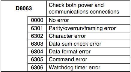
26 7.7 Error Registers Table 7.5: Error Registers 7.8 Error Codes Table 7.6: Error Codes 26

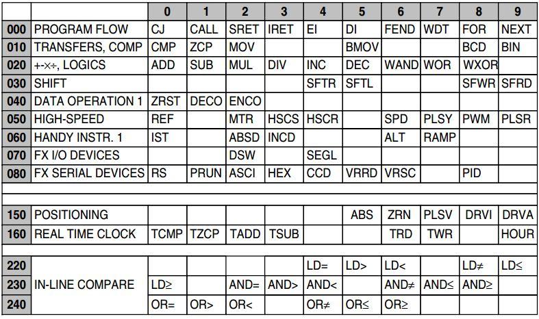
27 7.9 Instruction List Table 7.7: Numerically Sorted 27


28 Table 7.8: Alphabetically sorted HCFA Corporation Limited 7.10 Device List Table 7.9: Device List Device Type Specification Remarks Program capacity 2k steps by HCA1 internal EEPROM or 2k steps by TX1N-EEPROM-8L I/O configuration Max total I/O set by Main Processing Unit Auxiliary General 384 points M0 to M383 relay Latched 128 points M384 to M511 28
29 (M coils) (EEPROM backed-up) Special 256 points From the range M8000 to M8255 State relays Latched 128 points S0 to S127 (S coils) (EEPROM backed-up) Initial 10 points (subset) S0 to S9 Timers (T) 100 msec 63 points T0 to T62 Range: 0.1 to 3,276.7 sec 10 msec 31 points T32 to T62 when special M Range: 0.01 to sec coil M8028 is driven ON 1 msec 1 point T63 Range: to sec Counters Genera 16 points Range: 1 to 32,767 counts C0 to C15 Type: 16 bit up counter Latched (EEPROM 16 points Range: 1 to 32,767 counts C16 to C31 Type: 16 bit up counter backed-up) High speed 1 phase Range: -2,147,483,648 to C235 to C240, 6 points counters (C) 1 phase +2,147,483,647 counts C241to C245, 5 points Max. 6 c/w start General rule: Select points stop input counter combinations with 2 phase a combined counting C246 to C250, 5 points A/B phase frequency of 60kHz or C251 to C255, 5 points less. Note; all counters are latched (EEPROM backed-up) If high speed counter is used with the HSCS or HSCR instruction, a combined counting frequency of 30kHz or less Data registers (D) General 128 points D0 to D127 Type: 16 bit data storage register pair for 32 bit device Latched (EEPROM backed-up) 128 points D128 to D255 Type: 16 bit data storage register pair for 32 bit device File Maximum 1500 points D1000 to D2499 set by 29
30 parameter in 3 blocks of 500 program steps Type: 16 bit data storage register Externally 2 points D8030 & D8031 adjusted Range: 0 to 255 Data is entered indirectly through the external setting potentiometer Special 256 points From the range D8000 to (inclusive of D8013) D8255 Type: 16 bit data storage register Index 16 points V0 to V7, Z0 to Z7 Type: 16 bit data storage register Pointers (P) For use 64 points P0 to P63 with CJ, CALL For use with 6 points I00 to I50 interrupts (rising trigger = 1, falling trigger = 0) Nest levels 8 points for use with MC N0 to N7 and MCR Constants Decimal K 16 bit: -32,768 to +32, bit: -2,147,483,648 to +2,147,483,647 Hexadecimal 16 bit: 0000 to FFFF H 32 bit: to FFFFFFFF 30
HARDWARE MANUAL HCA2 SERIES PROGRAMMABLE CONTROLLERS
 HARDWARE MANUAL HCA2 SERIES PROGRAMMABLE CONTROLLERS Foreword... 3 1. Introduction... 6 1.1 Model Name... 7 1.2 Rules of Expansion... 7 1.3 Back up Data... 8 1.3.1 EEPROM backup... 8 1.3.2 Capacitor backup...
FX1N JAPANESE SPECIFICATION UNITS
 FX1N JAPANESE SPECIFICATION UNITS HARDWARE MANUA JY997D071A This manual contains safety information, associated manual listings, specifications and terminal layouts and wiring for Japanese specification
FX1N-4EX-BD Input Expansion Board
 Input Expansion Board USER S MANUAL JY992D95001C This manual contains text, diagrams and explanations which will guide the reader in the correct installation, safe use and operation of the FX 1N-4EX-BD
FX1N-2EYT-BD Output Expansion Board
 FX1N-2EYT-BD Output Expansion Board USER S MANUAL JY992D95201C This manual contains text, diagrams and explanations which will guide the reader in the correct installation, safe use and operation of the
User safety and equipment protection guidelines
 Snap-in I/O Module The V200-18-E1 plugs directly into the back of compatible Unitronics OPLCs, creating a selfcontained PLC unit with a local I/O configuration. The module offers: 3 analog inputs 16 digital
IO-DI8-TO8 I/O Expansion Module 8 Inputs, 8 Outputs
 IO-DI8-TO8 I/O Expansion Module 8 Inputs, 8 Outputs The IO-DI8-TO8 is an I/O expansion module that can be used in conjunction with specific Unitronics OPLC controllers. The module offers 8 digital inputs,
V E1B Snap-in I/O Module
 V200-18-E1B Snap-in I/O Module The V200-18-E1B plugs directly into the back of compatible Unitronics OPLCs, creating a selfcontained PLC unit with a local I/O configuration. Features 16 isolated digital
V E2B Snap-in I/O Module
 V200-18-E2B Snap-in I/O Module The V200-18-E2B plugs directly into the back of compatible Unitronics OPLCs, creating a selfcontained PLC unit with a local I/O configuration. Features 16 isolated digital
IO-DI8-TO8, IO-DI8-TO8-L I/O Expansion Modules 8 Inputs, 8 Outputs
 IO-DI8-TO8, IO-DI8-TO8-L I/O Expansion Modules 8 Inputs, 8 Outputs The IO-DI8-TO8 and IO-DI8-TO8-L are I/O expansion modules that can be used in conjunction with specific Unitronics OPLC controllers. The
HARDWARE MANUAL FX1N SERIES PROGRAMMABLE CONTROLLERS
 HARDWARE MANUAL FX1N SERIES PROGRAMMABLE CONTROLLERS FX1N Series Programmable Controllers Foreword This manual contains text, diagrams and explanations which will guide the reader in the correct installation
USER S MANUAL. FX2N-32DP-IF Profibus-DP Interface Unit
 USER S MANUAL FX2N-32DP-IF Profibus-DP Interface Unit FX2N-32DP-IF Profibus-DP Interface Unit Foreword This manual contains text, diagrams and explanations which will guide the reader in the correct installation
High Speed Remote I/O Module
 High Speed Remote I/O Module EXF-RC15 The Unitronics EXF-RC15 is a High Speed Remote I/O Module that offers three High Speed Counter inputs and four high speed outputs. Overall, the EXF-RC15 offers 9 digital
When any of the following symbols appear, read the associated information carefully. Symbol Meaning Description
 Uni-I/O Wide Modules Installation Guide UID-W1616R, UID-W1616T Uni-I/O Wide is a family of Input/Output modules that are compatible with the UniStream control platform. Wide Modules are 1.5 times as wide
V E1B Snap-in I/O Module
 V200-18-E1B Snap-in I/O Module The V200-18-E1B plugs directly into the back of compatible Unitronics OPLCs, creating a selfcontained PLC unit with a local I/O configuration. Features 16 isolated digital
HARDWARE MANUAL FX1S SERIES PROGRAMMABLE CONTROLLERS
 HARDWARE MANUAL FX1S SERIES PROGRAMMABLE CONTROLLERS FX1S Series Programmable Controllers Foreword This manual contains text, diagrams and explanations which will guide the reader in the correct installation
IO-PT4. Component identification. User safety and equipment protection guidelines. Unitronics Industrial Automation Systems 1
 IO-PT4 I/O Expansion Module 4 PT100 Inputs (-50 to 460 C) The IO-PT4 is an I/O expansion module that can be used in conjunction with specific Unitronics OPLC controllers. The module offers 4 PT100 inputs
V E2B Snap-in I/O Module
 i4 Automation Ltd - 01480 395256 V200-18-E2B Snap-in I/O Module The V200-18-E2B plugs directly into the back of compatible Unitronics OPLCs, creating a selfcontained PLC unit with a local I/O configuration.
When any of the following symbols appear, read the associated information carefully. Symbol Meaning Description
 Uni-I/O Modules Installation Guide UID-0808R, UID-0808T, UID-1600,UID-0016R, UID-0016T Uni-I/O is a family of Input/Output modules that are compatible with the UniStream control platform. This guide provides
IO-DI8-RO8, IO-DI8-RO8-L I/O Expansion Modules 8 Inputs, 8 Outputs
 IO-DI8-RO8, IO-DI8-RO8-L I/O Expansion Modules 8 Inputs, 8 Outputs The IO-DI8-RO8 and IO-DI8-RO8-L are I/O expansion modules that can be used in conjunction with specific Unitronics OPLC controllers. The
USER'S GUIDE FX-485ADP COMMUNICATION ADAPTER FX0N-485ADP COMMUNICATION ADAPTER
 FX- COMMUNICATION ADAPTER FX0N- COMMUNICATION ADAPTER USER'S GUIDE JY992D53201C This manual contains text, diagrams and explanations which will guide the reader in the correct installation and operation
IO-AO6X I/O Expansion Module 6 Isolated Analog Outputs
 IO-AO6X I/O Expansion Module 6 Isolated Analog Outputs The IO-AO6X is an I/O Expansion Module that can be used in conjunction with specific Unitronics OPLC controllers. The module offers 6 12-bit isolated
INSTRUCTION SHEET. Eaton Logic Controller ELCB Controllers
 2010-12-10 5011699201-PBB1 Eaton Logic Controller ELCB Controllers INSTRUCTION SHEET [Applicable Controllers] ELCB-PB10 ELCB-PB14 ELCB-PB20 ELCB-PB30 ELCB-PB40 IL05001005E 002-1310020-02 Thank you for
V E5B Snap-in I/O Module
 V200-18-E5B Snap-in I/O Module The V200-18-E5B plugs directly into the back of compatible Unitronics OPLCs, creating a selfcontained PLC unit with a local I/O configuration. Features 18 isolated digital
WARNING 25.2 POWER L.V X1 X2 Y0 C1 Y1 C2 Y2 C3 Y3 ELC-EX NN. 3. Extension unit clip 4. Input/output terminal
 POWER L.V 006--7 506000-E ELC-ENNDR/T ELC-E6NNDR/T ELC-ENNDN ELC-ENNAN ELC-ENNNR/T ELC-E6NNNI Instruction Sheet Digital Input Digital Output Module WARNING This Instruction Sheet provides descriptions
IO-DI8-RO4, IO-DI8-RO4-L I/O Expansion Modules 8 Inputs, 4 Outputs
 IO-DI8-RO4, IO-DI8-RO4-L I/O Expansion Modules 8 Inputs, 4 Outputs The IO-DI8-RO4 and IO-DI8-RO4-L are I/O expansion modules that can be used in conjunction with specific Unitronics OPLC controllers. The
When any of the following symbols appear, read the associated information carefully. Symbol Meaning Description
 Uni-I/O Wide Modules Installation Guide UIS-WCB1 Uni-I/O Wide is a family of Input/Output modules that are compatible with the UniStream control platform. Wide Modules are 1.5 times as wide as Uni-I/O
When any of the following symbols appear, read the associated information carefully. Symbol Meaning Description
 Uni-I/O Modules Installation Guide UID-0808THS Uni-I/O is a family of Input/Output modules that are compatible with the UniStream control platform. This guide provides basic installation information for
USER S MANUAL. FX2N-64DNET DeviceNet Interface Block
 USER S MANUAL FX2N-64DNET DeviceNet Interface Block FX2N-64DNET DeviceNet Interface Block Foreword This manual contains text, diagrams and explanations which will guide the reader in the correct installation
Vision OPLC V TR6/V350-J-TR6
 Vision OPLC V350-35-TR6/V350-J-TR6 Installation Guide The Unitronics V350-35-TR6/V350-J-TR6 offers the following onboard I/Os: 8 Digital Inputs, configurable via wiring to include 2 Analog (current/voltage)
1) Indicates that the identified danger WILL cause physical and property damage.
 Indicates that the identified danger WILL cause physical and property damage.") FX INPUT AND OUTPUT TERINAL BLOKS USER S GUIDE JY99DE This manual contains text, diagrams and explanations which will guide the reader in the correct installation and operation of the FX TERINAL BLOKS.
FX INPUT AND OUTPUT TERINAL BLOKS USER S GUIDE JY99DE This manual contains text, diagrams and explanations which will guide the reader in the correct installation and operation of the FX TERINAL BLOKS.
EX-RC1 Remote I/O Adapter
 EX-RC1 Remote I/O Adapter The EX-RC1 interfaces between Unitronics Vision OPLCs and remote I/O Expansion Modules distributed throughout your system. The adapter is connected to a PLC via CANbus. Each adapter
When any of the following symbols appear, read the associated information carefully. Symbol Meaning Description
 Vision OPLC V350-35-R34/V350-J-R34 Installation Guide The Unitronics V350-35-R34/V350-J-R34 offers the following onboard I/Os: 22 Digital Inputs, configurable via wiring to include 2 Analog and 3 HSC/Shaft-encoder
EH21 DVP
 2009-06-15 5011668901-EH21 DVP-1070030-02 ENGLISH This Instruction Sheet only provides descriptions for electrical specifications, general specifications, installation & wiring. Other detail infromation
V E62B Snap-in I/O Module
 V200-18-E62B Snap-in I/O Module The V200-18-E62B plugs directly into the back of compatible Unitronics OPLCs, creating a selfcontained PLC unit with a local I/O configuration. Features 30 isolated digital
FX-10GM POSITIONING CONTROLLER USER'S GUIDE
 FX-10GM POSITIONING CONTROLLER USER'S GUIDE Manual number: JY992D68401 Manual revision: A Date: September 1997 Foreword This manual only describes the specifications for FX-10GM positioning controller.
When any of the following symbols appear, read the associated information carefully. Symbol Meaning Description
 Uni-I/O Modules Installation Guide UIA-0402N Uni-I/O is a family of Input/Output modules that are compatible with the UniStream control platform. This guide provides basic installation information for
OPLC Installation Guide
 Samba OPLC SM35-J-R20/SM43-J-R20 SM70-J-R20 SM35-J-T20/SM43-J-T20 SM70-J-T20 OPLC Installation Guide 12 Digital Inputs, include 1 HSC/Shaft-encoder Input, 2 Analog inputs (only when the digital inputs
CONTROL ANYTHING WITH YOUR CELLPHONE. Use your cellphone to remotely monitor and control the following applications with the CELLSWITCH 100
 CELLSWITCH 100 CONTROL ANYTHING WITH YOUR CELLPHONE Use your cellphone to remotely monitor and control the following applications with the CELLSWITCH 100 Security: Electric Fence / Power-failure / Fire
USP-070-B08 USP-104-B10, USP-104-M10 USP-156-B10
 UniStream HMI Panel Installation Guide USP-070-B10, USP-070-B08 USP-104-B10, USP-104-M10 USP-156-B10 Unitronics UniStream platform comprises control devices that provide robust, flexible solutions for
IO-DI16, IO-DI16-L I/O Expansion Modules
 IO-DI16, IO-DI16-L I/O Expansion Modules 16 Digital Inputs The IO-DI16 and IO-DI16-L are I/O expansion modules that can be used in conjunction with specific Unitronics OLC controllers. The modules are
USER S MANUAL. FX2N-32ASI-M AS-interface Master Block
 USER S MANUAL FX2N-32ASI-M AS-interface Master Block FX2N-32ASI-M AS-interface Master Block Foreword This manual contains text, diagrams and explanations which will guide the reader in the correct installation
The identified danger could cause physical and property damage.
 Samba OPLC SM35-J-T20 Installation Guide The Unitronics SM35-J-T20 offers the following onboard I/Os: 12 Digital Inputs, configurable via wiring to include 2 Analog and 3 HSC/Shaft-encoder Inputs 8 Transistor
HITACHI. EH-150 series PLC EH-RTD8 Resistance Temperature Detective input module Instruction manual. Safety precautions
 HITACHI EH-150 series PLC Resistance Temperature Detective input module Instruction manual Thank you for purchasing a Hitachi Programmable Logic Controller. To operate it safely, please read this instruction
Vision OPLC V TR20/V350-J-TR20
 Vision OPLC V350-35-TR20/V350-J-TR20 Installation Guide The Unitronics V350-35-TR20/V350-J-TR20 offers the following onboard I/Os: 12 Digital Inputs, configurable via wiring to include 2 Analog, and 3
Operating instructions. Standstill monitor A / / 2011
 Operating instructions Standstill monitor A300 UK 1 2 3 4 5 6 7 8 7390337 / 01 02 / 2011 1 2 3 4 5 6 7 8 switchpoint min max pulse/min power Made in Germany ifm electronic gmbh D 45127 Essen func. I II
Vision OPLC. V T38 Installation Guide. General Description
 Vision OPLC V130-33-T38 Installation Guide The Unitronics V130-33-T38 offers the following onboard I/Os: 22 Digital Inputs, configurable via wiring to include 2 Analog and 2 HSC/Shaft-encoder Inputs 16
FX2N-4AD-PT SPECIAL FUNCTION BLOCK
 FX2N-4AD-PT SPECIAL FUNCTION BLOCK USER S GUIDE JY992D65601G This manual contains text, diagrams and explanations which will guide the reader in the correct installation and operation of the FX2N-4AD-PT
When any of the following symbols appear, read the associated information carefully. Symbol Meaning Description
 Uni-I/O Modules Installation Guide UIS-04PTN Uni-I/O is a family of Input/Output modules that are compatible with the UniStream control platform. This guide provides basic installation information for
LOGIC CONTROLLER INSTALLATION MANUAL NTR 756 B /E
 LOGIC CONTROLLER INSTALLATION MANUAL NTR 756 B /E Table of contents 1. INTRODUCTION...1 2. HARDWARE DESCRIPTION...2 3. INSTALLATION...6 4. CONNECTION...8 5. USER SAFETY AND PROTECTION OF THE EQUIPMENT...11
This guide provides basic information for Unitronics controller model V T2.
 Vision OPLC 12 pnp/npn Digital, including 2 Analog, 3 HSC/Shaftencoder Inputs, 12 Transistor Outputs This guide provides basic information for Unitronics controller model V350-35-T2. General Description
Operating instructions. Switching amplifier DN0210 DN / / 2015
 Operating instructions Switching amplifier DN0210 DN0220 UK 80011079 / 00 01 / 2015 Contents 1 Preliminary note...4 1.1 Symbols used...4 1.2 Warning signs used...4 2 Safety instructions...5 2.1 General...5
Vision OPLC V TR20
 Vision OPLC V130-33-TR20 Installation Guide The Unitronics V130-33-TR20 offers the following onboard I/Os: 12 Digital Inputs, configurable via wiring to include 2 Analog, and 3 HSC/Shaft-encoder Inputs
Micro-OPLC Installation Guide
 Jazz OPLC Micro-OPLC Installation Guide 6 Digital Inputs, 4 Relay Outputs 6 Digital, 2 Analog/Digital, 2 Analog Inputs, 6 Relay Outputs Before using this product, the user must read and understand this
EX-RC1 Remote I/O Adapter
 EX-RC1 Remote I/O Adapter The EX-RC1 interfaces between Unitronics Vision OPLCs and remote I/O Expansion Modules distributed throughout your system. The adapter is connected to a PLC via CANbus. Each adapter
This guide provides basic information for Unitronics Models 230/260/280/290 (Non-color Screens).
.") Vision OPLC Installation Guide Models 230/260/280/290 (Non-color Screens) This guide provides basic information for Unitronics Models 230/260/280/290 (Non-color Screens). General Description Vision OPLCs
Vision OPLC Installation Guide Models 230/260/280/290 (Non-color Screens) This guide provides basic information for Unitronics Models 230/260/280/290 (Non-color Screens). General Description Vision OPLCs
22 Digital Inputs, including 2 Analog, 2 HSC/Shaft-encoder inputs 16 Transistor Outputs
 Vision PLC+HMI V130-33-T38/V130-J-T38 V350-35-T38/V350-J-T38 V430-J-T38 Installation Guide 22 Digital Inputs, including 2 Analog, 2 HSC/Shaft-encoder inputs 16 Transistor Outputs General Description All
Operating instructions. Speed monitor D / / 2014
 Operating instructions Speed monitor D200 80005257 / 00 05 / 2014 Contents 1 Preliminary note...4 1.1 Symbols used...4 1.2 Warning signs used...4 2 Safety instructions...5 2.1 General...5 2.2 Target group...5
EX-RC1 Remote I/O Adapter
 EX-RC1 Remote I/O Adapter The EX-RC1 interfaces between Unitronics Vision OPLCs and remote I/O Expansion Modules distributed throughout your system. The adapter is connected to a PLC via CANbus. Each adapter
Screen 2.4" 3.5" Color Touch 4.3" Color Touch. RS232/485 Yes Yes Yes Yes Yes* USB device, mini-b Com Ports, separate order, user-installed
 V130-33-TR20/V130-J-TR20 V350-35-TR20/V350-J-TR20 V430-J-RH2 Installation Guide 12 Digital Inputs, including 2 Analog, 3 HSC/Shaft-encoder inputs 6 Relay Outputs 2 high-speed npn Transistor Outputs (TR20
General Description V TR34/V130-J-TR34 V TR34/V350-J-TR34 V430J-R34 V R34/V130-J-R34 V R34/V350-J-R34
 Vision OPLC V130-33-TR34/V130-J-TR34 V350-35-TR34/V350-J-TR34 V430-J-TR34 V130-33-R34/V130-J-R34 V350-35-R34/V350-J-R34 V430-J-R34 Installation Guide 22 Digital Inputs, including 3 HSC/Shaft-encoder Inputs,
Failure to comply with appropriate safety guidelines can cause severe injury or property damage.
 Jazz OPLC Micro-OPLC Installation Guide 6 Digital Inputs, 4 Relay Outputs 6 Digital, 2 Analog/Digital, 2 Analog Inputs, 6 Relay Outputs Before using this product, the user must read and understand this
Model Number Structure
 Solid State Relays with Failure Detection Function G3PC CSM_G3PC_DS_E_1_1 Refer to Safety Precautions for All Solid State Relays. Detects failures in SSR used for heater temperature control and simultaneously
Expansion Unit Catalog Nos , - 152, - 153, - 154, - 156, -E157
 PRODUCT DA TA SLC 150 110 Expansion Unit Catalog Nos. 1745-151, - 152, - 153, - 154, - 156, -E157 7 : The EXpdnSiQn Unit The SLC 150 expansion unit can be used with either the SLC 150 processor unit or
H Series PLC. ! : Indicates Compulsion. EH-150 Analog input module EH-AXH8M Instruction manual. Safety precautions DANGER CAUTION COMPULSION
 H Series PLC EH-150 Analog input module EH-AXH8M Instruction manual Thank you for purchasing a Hitachi Programmable Logic Controller. To operate it safely, please read this instruction manual and all the
Allen-Bradley PLCs. 100 Programmable Controller Processor Unit -Catalog Nos LPI01, -LP102, -LP103, -LP104 SLC TM. The Unit
 PRODUCT DATA SLC TM 100 Programmable Controller Processor Unit -Catalog Nos. 1745-LPI01, -LP102, -LP103, -LP104 The SLC 100 programmab/e Contro"er The SLC 100 Programmable Controller is easy to program,
UniStream CPU-for-Panel
 UniStream CPU-for-Panel Installation Guide USC-P-B10 Unitronics UniStream platform comprises control devices that provide robust, flexible solutions for industrial automation. This guide provides basic
Making Hazardous Operations Safe and Productive
 NEW Safety Guard Switching Unit G9SX-GS Making Hazardous Operations Safe and Productive Making Hazardous Operations Safe and Productive This new addition to the model of Flexible Safety Unit G9SX series
Vision OPLC V TR20
 Vision OPLC V130-33-TR20 Installation Guide The Unitronics V130-33-TR20 offers the following onboard I/Os: 12 Digital Inputs, configurable via wiring to include 2 Analog, and 3 HSC/Shaft-encoder Inputs
Programmable Relay ZEN V2 Units
 Programmable Relay ZEN V2 Units Please read and understand this catalog before purchasing the products. Please consult your OMRON representative if you have any questions or comments. Refer to Warranty
S8VE (60/90/120/180/240-W Models)
") Switch Mode Power Supply S8VE (60/90/120/180/240-W Models) CSM_S8VE_DS_E_1_1 60/90/120/180/240-W Models Improved Versions of Standard-type Power Supplies without Indication Monitor. Safety standards: UL508/60950-1,
Switch Mode Power Supply S8VE (60/90/120/180/240-W Models) CSM_S8VE_DS_E_1_1 60/90/120/180/240-W Models Improved Versions of Standard-type Power Supplies without Indication Monitor. Safety standards: UL508/60950-1,
Component identification
 IO-ATC8 I/O Expansion Module 8 Analog/Thermocouple Inputs The IO-ATC8 is an I/O Expansion Module that can be used in conjunction with specific Unitronics OPLC controllers. The module offers 8 inputs that
170 ADM to 60 VDC Module Base / 170 ADO Pt. Relay Out Module Base. Version 1.0
 170 ADM 850 10 10 to 60 VDC Module Base / 170 ADO 830 30 6 Pt. Relay Out Module Base Version 1.0 31005197 00 Safety Information NOTICE Read these instructions carefully, and look at the equipment to become
Installation Guide V290 (Color) This guide provides basic information for Unitronics LCD color touchscreen models V C30B and V T40B.
 This guide provides basic information for Unitronics LCD color touchscreen models V C30B and V T40B.") Vision OPLC Installation Guide V290 (Color) This guide provides basic information for Unitronics LCD color touchscreen models V290-19-C30B and V290-19-T40B. General Description Vision OPLCs are programmable
Vision OPLC Installation Guide V290 (Color) This guide provides basic information for Unitronics LCD color touchscreen models V290-19-C30B and V290-19-T40B. General Description Vision OPLCs are programmable
FX-485PC-IF RS485 Interface Unit Hardware Manual
 JY992D81801B Date: 2015 April FX- RS485 Interface Unit Hardware Manual This manual contains text, diagrams and explanations which will guide the reader in the correct installation and operation of the
Remote I/O Unit with Connectors for Light Curtain CC-Link Safety System. panasonic.net/id/pidsx/global
 715 LIGHT CURTAINS / USE Remote I/O Unit with Connectors for Light Curtain CC-Link System General terms and conditions... F-7 Related Information... P.703~ SF4B... P.565~ General precautions... P.1501
UniStream HMI Panel. CPU-for-Panel
 UniStream HMI Panel Installation Guide USP-070-B10,USP-104-B10, USP-156-B10 Unitronics UniStream platform comprises control devices that provide robust, flexible solutions for industrial automation. This
IV-30 Operating Manual for Pulse Distributor Cassette with potential separation
 IV-30 Operating Manual for Pulse Distributor Cassette with potential separation Edition-/Rev.-Date: 09/08/2006 Document-/Rev.-No.: TR - EAK - BA - GB - 0093-02 Software version: - File name: TR-EAK-BA-GB-0093-02.DOC
over time. Improper wiring practices could result in drive malfunction due to loose terminal connections. Control Circuit Terminal Block Functions Dri
 Figure 3.14 Main speed frequency reference. Multi-function programmable Safety input Forward run/stop Reverse run/stop External fault Fault reset Multi-step speed 1 main/aux switch Multi-step speed 2 Jog
VB -1HC SPECIAL FUNCTION BLOCK USER'S GUIDE
 VB -1HC SPECIAL FUNCTION BLOCK USER'S GUIDE This manual contains text, diagrams and explanations which will guide the reader in the correct installation and operation of the VB -1HC special function block
INSTRUCTION SHEET. Eaton Logic Controller ELCM Controllers
 2010-12-10 5011698901-PHA1 Eaton Logic Controller ELCM Controllers INSTRUCTION SHEET [Applicable Controllers] ELCM-PH16NNDR ELCM-PH16NNDT ELCM-PH24NNDR ELCM-PH24NNDT ELCM-PH32NNDR ELCM-PH32NNDT ELCM-PH40NNDR
Output Terminal Module
 Output Terminal Module FA-TH16YRA11/11S/20/20S/20SL/21/21S,FA-TH16YRAC20S, FA-TH16YRAB20SL,FA-TH16YSR11S/20S/21S, FA-TH16YTL11S/21S,FA-TH16YTH11S,FA-TH16YTR20S, FA-TH16Y2TR20,FA-THE16YTH11S,FA-THE16YTR20S
FX2NC-ENET-ADP Ethernet adapter USER'S MANUAL
 Y1 Y0 Y2 2NC POWER LINK ACT SD RD - Ethernet adapter USER'S MANUAL Manual Number JY997D12301 Revision D Date May 2007 This manual contains text, diagrams and explanations which guide the reader in the
ACCESS 9340/9360 Meter Input/Output Module
 Installation Manual PMIM-IOMOD-0208 ACCESS 9340/9360 Meter Input/Output Module 9340-60-I/O2222 and 9340-60-I/O26 HAZARD CATEGORIES AND SPECIAL SYMBOLS Read these instructions carefully and look at the
Communication & Networking
 MicroSmart Master Module Capable of Connecting 62 Slaves Compliance with Ver. 2.1 specifi cations Digital and analog slaves can be connected. Configuration and slave monitoring can be done using LED indicators
USER S MANUAL. FX2N-5A Special function block
 USER S MANUAL FX2N-5A Special function block FX2N-5A Special function block Foreword This manual contains text, diagrams and explanations which will guide the reader in the correct installation and operation
When any of the following symbols appear, read the associated information carefully. Symbol Meaning Description
 Uni-COM Modules Installation Guide UAC-01RS2,UAC-02RS2,UAC-02RSC Uni-COM is a family of communication modules that are compatible with the UniStream control platform. This guide provides basic installation
HARDWARE MANUAL FX1S SERIES PROGRAMMABLE CONTROLLERS
 HARDWARE MANUAL FX1S SERIES PROGRAMMABLE CONTROLLERS FX1S Series Programmable Controllers Foreword This manual contains text, diagrams and explanations which will guide the reader in the correct installation
G9SX-GS. Safety Guard Switching Unit. A Safety Measure for Hazardous Operations That Does Not Lower Productivity. Auto Switching Function
 Safety Guard Switching Unit CSM DS_E_6_1 A Safety Measure for Hazardous Operations That Does Not Lower Productivity Two functions support two types of application: Auto switching: For applications where
Line reactors SINAMICS. SINAMICS G130 Line reactors. Safety information 1. General. Mechanical installation 3. Electrical installation
 Safety information 1 General 2 SINAMICS SINAMICS G130 Mechanical installation 3 Electrical installation 4 Technical specifications 5 Operating Instructions Control version V4.7 04/2014 A5E00331462A Legal
GENERAL PRECAUTIONS GENERAL DESCRIPTION... 6
 Cat.No I173E-EN-01 RX Inverter Expansion I/O Board 3G3AX-EIO21-ROE USER S MANUAL GENERAL PRECAUTIONS... 3 1 GENERAL DESCRIPTION... 6 2 INSTALLATION PROCEDURE... 7 2.1 INSTALLING THE EXPANSION I/O BOARD...
V TU24 V350-J-TU24
 Vision PLC+HMI V350-35-TU24 V350-J-TU24 Installation Guide 12 Digital Inputs, including 2 Analog, 2 PT100/TC,1 HSC/Shaft-encoder input 12 Transistor Outputs General Description All of the controllers covered
MC 11 EB-2 Power supply cabinet with external bus, AC version
 MC 11 EB-2 Power supply cabinet with external bus, AC version USER/MAINTENANCE MANUAL 1 SLOT 0 SLOT 1 SLOT 2 SLOT 3 SLOT 4 SLOT 5 SLOT 6 SLOT 7 SLOT 8 SLOT 9 SLOT 10 SLOT 11 EB-2 (a) MC11 (b) (c) Figures
Operating instructions AS-i SmartLine module AC3200 AC /00 06/2016
 Operating instructions AS-i SmartLine module AC3200 AC3201 80237876/00 06/2016 Contents 1 Preliminary note...3 1.1 Symbols used...3 1.2 Warnings used...3 2 Safety instructions...3 2.1 General...3 2.2 Target
TOP - 1. Instruction Manual. Version 1.0 Produced in Jan. 2004
 Version 1.0 Produced in Jan. 2004 Instruction Manual LCD monitor IV-08MP Thank you for purchasing the SHARP IV-08MP LCD monitor. Read this introductory instruction manual carefully to thoroughly familiarize
EE-SPX74/84. Ordering Information. Compact Sensor for High-Density Mounting with Easy Snap-In Connector. H Connector features a built-in safety
 Compact for High-Density Mounting with Easy Snap-In Connector H Connector features a built-in safety lock for shock and vibration resistance H replacement made simple without rewiring H Cables can be bent
output devices. connected to the controller. data communications link. relay systems. user program. MECH1500Quiz1ReviewVersion2 Name: Class: Date:
 Class: Date: MECH1500Quiz1ReviewVersion2 True/False Indicate whether the statement is true or false. 1. The number and type of I/Os cannot be changed in a fixed PLC. 2. In a PLC system, there is a physical
Safety Control. FS1A Multi-function Safety Relay. Optional Parts. Connecting Tool. Marked Cable Tie. DIN Rail BNDN1000 Aluminum, 1m 35mm wide
 Multi-function Relay Key features: No programming required. Configuration complete by turning on a logic switch A safety circuit can be configured easily just by selecting a logic from eight preprogrammed
Operating instructions Evaluation system for flow sensors VS / / 2013
 Operating instructions Evaluation system for flow sensors VS3000 7097 / 0 07 / 203 Contents Preliminary note...2 2 Safety instructions...3 3 Function and features... Mounting.... Mounting of the sensors...
Contact protection relay
 Contact protection relay Ordering details SVR 450 08 F0000 The protects sensitive control contacts from excessive load. It can be used with latching function or without. Bounce time of control contacts
Operating Instructions. For. Level Control Module. Model SSR 1000
 Operating Instructions For Level Control Module Model SSR 1000 SSR Operation Instructions Rev. 1 Jan 01 Page 1/7 1. Note Please read and take note of these operating instructions before unpacking and commissioning.