PIC Dev 14 Surface Mount PCB Assembly and Test Lab 1
|
|
|
- Loraine Singleton
- 5 years ago
- Views:
Transcription

1 Name Lab Day Lab Time PIC Dev 14 Surface Mount PCB Assembly and Test Lab 1 Introduction: The Pic Dev 14 SMD is a simple 8-bit Microchip Pic microcontroller breakout board for learning and experimenting with small embedded systems. Using a board like makes it possible to work with surface mount devices while experimenting on a breadboard. The small Microchip Pic microcontrollers use a common pinout for power and programming interfaces so this board is compatible with many different chips. Lab Requirements: 1. Demonstration of a working PIC Dev 14 board by showing blinking LED. 2. Complete the section on setting the LED current. 3. Complete the section on black box testing. About the PIC Dev 14: To get started with this lab you will need to assemble a small development board for a 14-pin PIC microcontroller. This board was designed to simplify the task of getting started with a bare microcontroller by including some minimal support circuitry. The board will be used for a number of the labs that will be performed throughout the semester. The PIC Dev 14 board provides an interface for programming 14-pin (and smaller) PIC microcontrollers in addition to an LED and trim pot for performing simple experiments. Access to all the microcontroller pins is available on two headers spaced to fit on a standard breadboard. PIC Dev 14 SMD Assembly


2 PIC Dev 14 SMD Schematic: PIC Dev 14 SMD PCB: Silkscreen and Pads Top Copper Bottom Copper Connecting the Programmer:
3 Setting the LED Current: While developing firmware, it is often useful to have an LED blinking at a periodic rate to show that your system is powered up and running (heartbeat indicator). The schematic shows a 560Ω Resistor in series with the LED to set the maximum current through the LED. This value was chosen to set the brightness for a specific type of LED (color, size and efficiency). The LED that you select for your board will most likely be different and require a different resistor value to get a desirable intensity. Current through the LED: for example Most digital multimeter s (DMM) have a DIODE mode that is useful for measuring the forward voltage of a semiconductor junction at a given current. The test current is typically between 100µA and 1mA which is low enough to prevent damage to the device but high enough to get an estimate of the forward voltage. This estimate will be good enough for today s calculations. Select an LED and measure the forward voltage using the DMM: Describe your LED (shape, color, size) Measured Vf How can you tell the anode from the cathode? Calculate the resistor needed for the following LED currents assuming VDD = 5V ILED 1mA R1 = ILED5mA R1 = ILED10mA R1 = Test your LED with the approximate values above and select a resistor that gives a luminous intensity that you are happy with. Value selected for R1 Construction: Review the schematic and printed circuit board layout then collect all the parts needed to assemble the PCB. Be careful to install the LED and microcontroller in the correct orientation. The polarity of the surface mount LED is indicated on the back side of the part and on the PCB silkscreen. Pin 1 of the PIC microcontroller faces towards the ICD programming header and is indicated on the silkscreen. A video showing how to build the board is available on the class webpage.

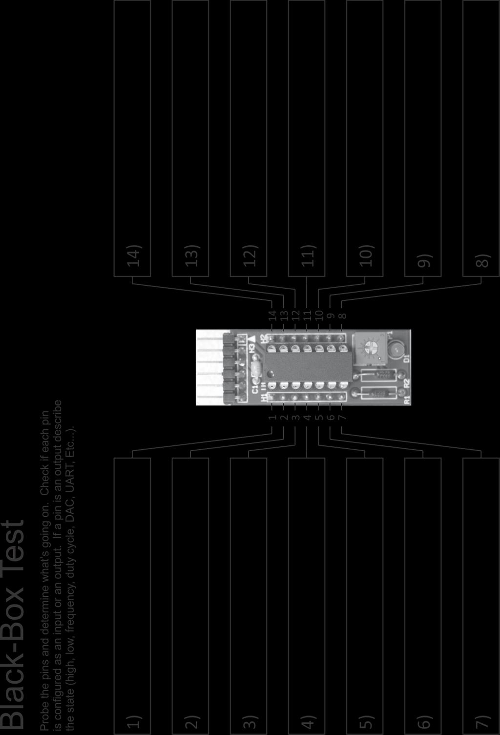
4 Connecting the power and Programming: Once your board is fully assembled inspect the solder joints and touchup any problem locations. If everything looks good, you are ready apply power to your board. Set the power supply to a voltage of 5V and a current limit of around 20mA. Double check the polarity of your circuit and apply power. If the power supply starts to current limit CC immediately disconnect the power and look for problems. If the voltage is stable CV then you are ready to program your chip. The firmware for today s lab is stored in the PICkit 3 configured in the Programmer to Go mode. In this mode, the PICkit 3 will program your microcontroller with the stored image when you plug it into the ICSP header and press the black button. For this to work you will need to power the PICkit 3 by connecting the USB cable to a computer or power source however no software needs to installed or configured. If you board successfully programs the ACTIVE LED with blink blue and the POWER and STATUS LED will be green. If it fails to program the STATUS LED will flash red. PICkit 3 Programmer: Testing with the Oscilloscope: Now that your board is programmed turn on the oscilloscope and probe each of the pins to determine the status. Use a 1k resistor connected to either Gnd or Vdd to test if a pin is configured as an input or an output and to check if internal pull-ups have been enabled.
5
PIC Dev 14 Through hole PCB Assembly and Test Lab 1
 Name Lab Day Lab Time PIC Dev 14 Through hole PCB Assembly and Test Lab 1 Introduction: The Pic Dev 14 is a simple 8-bit Microchip Pic microcontroller breakout board for learning and experimenting with
LED Knight Rider. Yanbu College of Applied Technology. Project Description
 LED Knight Rider Yanbu College of Applied Technology Project Description This simple circuit functions as a 12 LED chaser. A single illuminated LED 'walks' left and right in a repeating sequence, similar
PIC 28 Pin Board Documentation. Update Version 5.0
 PIC 28 Pin Board Documentation Update 2009.10 Version 5.0 Table of Contents PIC 28 Pin Board Documentation... 1 Table of Contents... 2 Introduction... 3 Circuit Schematic... 4 The following is the Circuit
AT42QT101X Capacitive Touch Breakout Hookup Guide
 Page 1 of 10 AT42QT101X Capacitive Touch Breakout Hookup Guide Introduction If you need to add user input without using a button, then a capacitive touch interface might be the answer. The AT42QT1010 and
UF-3701 Power Board Construction Guide
 Page 1/5 Soldering and Part Placement See the Chapter 3 of the MIT 6270 Manual for information on electronic assembly, including soldering techniques and component mounting. Construction Information All
PIC KIT 2 BASIC-USERS GUIDE FEMTO ELECTRONICS
 PIC KIT 2 BASIC-USERS GUIDE FEMTO ELECTRONICS SPECIFICATIONS: ICSP (In Circuit Serial Programmer). Compatible with PIC Microcontrollers (5V chips only). Compatible with MPLAB, MPLAB X and PIC KIT 2 software.
Adafruit USB Power Gauge Mini-Kit
 Adafruit USB Power Gauge Mini-Kit Created by Bill Earl Last updated on 2017-07-14 11:55:04 PM UTC Guide Contents Guide Contents Overview Assembly Basic Assembly Solder the female connector. Solder the
BUILDING YOUR KIT. For the Toadstool Mega328.
 BUILDING YOUR KIT For the Toadstool Mega328 www.crash-bang.com @crashbang_proto This work is licensed under a Creative Commons Attribution-ShareAlike 4.0 International License. Congratulations! You re
A4988 Stepper Motor Driver Carrier, Black Edition
 A4988 Stepper Motor Driver Carrier, Black Edition A4988 stepper motor driver carrier, Black Edition, bottom view with dimensions. Overview This product is a carrier board or breakout board for Allegro
solutions for teaching and learning
 RKOneAnalogue Component List and Instructions PCB layout Constructed PCB Schematic Diagram RKOneAnalogue Software Development PCB Page 1 Description The RKOneAnalogue software development PCB has been
Rapid40i PIC Prototyping PCB User Manual
 Description This is a PCB designed to facilitate the rapid prototyping of a device based on a 40 pin Microchip PIC microcontroller. To allow users to focus on their application, we take care of key housekeeping
K191 3 Channel RGB LED Controller
 K191 3 Channel RGB LED Controller 1 Introduction. This kit has been designed to function as a versatile LED control module. The LED controller provides 3 high current channels to create light effects for
AT42QT1010 Capacitive Touch Breakout Hookup Guide
 Page 1 of 7 AT42QT1010 Capacitive Touch Breakout Hookup Guide Introduction If you need to add user input without using a button, then a capacitive touch interface might be the answer. The AT42QT1010 Capacitive
PCB-STM32-F3U. Development baseboard for the STMicro Discovery-F3 module (STMicro part# STM32F3DISCOVERY)
") PCB-STM32-F3U Development baseboard for the STMicro Discovery-F3 module (STMicro part# STM32F3DISCOVERY) Part Number: PCB-STM32-F3U (unpopulated PCB with Discovery module sockets, no other parts) STM32-F3U
PCB-STM32-F3U Development baseboard for the STMicro Discovery-F3 module (STMicro part# STM32F3DISCOVERY) Part Number: PCB-STM32-F3U (unpopulated PCB with Discovery module sockets, no other parts) STM32-F3U
Getting acquainted with the development tools June 27, 2006 ELE492 Embedded System Design Exercise 1
 Getting acquainted with the development tools June 27, 2006 ELE492 Embedded System Design Exercise 1 Overview In this first exercise, a few tasks are given to get acquainted with the PIC microcontroller
DEV16T. LCD Daughter board
 LCD Daughter board Table of Contents 1 Introduction...2 2 Features...3 3 Expansion Connectors...4 3.1 Daughter Board Connectors...4 4 LCD Display...5 5 Input Buttons S1 to S4...5 6 Buzzer...5 7 Connector
Advanced Strobe 1.0 Kit
 Kit Instruction Manual Eastern Voltage Research, LLC December 2013, Rev 1 1 http://www.easternvoltageresearch.com Kit Introduction to the Kit Thank you for purchasing the Kit. If you are looking for a
Good Idea to Working Electronic Model
 Good Idea to Working Electronic Model by Jan H. Lichtenbelt, March 2011 Abstract Seeing an idea manifest itself into a fully working creation is always satisfying, however so many good ideas go to waste
Infrared Add-On Module for Line Following Robot
 1 Infrared Add-On Module for Line Following Robot January 3, 2015 Jeffrey La Favre The infrared add-on module allows multiple line following robots to operate on the same track by preventing collisions
Thursday, September 15, electronic components
 electronic components a desktop computer relatively complex inside: screen (CRT) disk drive backup battery power supply connectors for: keyboard printer n more! Thursday, September 15, 2011 integrated
Features ================================= Auto Detects Programming Hardware and Inserted Devices
 13056 PIC Programmer - USB, ISP Programmer for Microchip PIC Microcontroller supports almost all 12F, 16F & 18F devices Features ================================= Auto Detects Programming Hardware and
PICado Alpha Development Board V1.0
 V1.0 Bluetooth Transceiver Module HC-05 Four onboard FET power output stage 34 freely assignable I/O pins ICSP interface 2015 Jan Ritschard, All rights reserved. V1.0 Table of Contents 1. Introduction...
Assembly Instructions (8/14/2014) Your kit should contain the following items. If you find a part missing, please contact NeoLoch for a replacement.
 Your kit should contain the following items. If you find a part missing, please contact NeoLoch for a replacement.") NeoLoch NLT-28P-LCD-5S Assembly Instructions (8/14/2014) Your kit should contain the following items. If you find a part missing, please contact NeoLoch for a replacement. Kit contents: 1 Printed circuit
NeoLoch NLT-28P-LCD-5S Assembly Instructions (8/14/2014) Your kit should contain the following items. If you find a part missing, please contact NeoLoch for a replacement. Kit contents: 1 Printed circuit
Microprocessors B Lab 3 Spring PIC24/24LC515 EEPROM Interface Using I 2 C
 PIC24/24LC515 EEPROM Interface Using I 2 C Lab Report Objectives Materials See separate report form located on the course webpage. This form should be completed during the performance of this lab. 1) To
VG-305A AC Traffic Light Controller Kit
 Galak Electronics Electronic kits and components Website: GalakElectronics.com Email: sales@galakelectronics.com Phone: (302) 832-1978 VG-305A AC Traffic Light Controller Kit Thank you for your purchase
NEDSP1068-PCBA NEDSP1068-PCBA-MIC DSP
 bhi Ltd PO Box 318, Burgess Hill, RH15 9NR England. Tel: +44 (0)1444 870333 Fax: +44 (0)845 217 9936 info@bhi-ltd.com, www.bhi-ltd.com NEDSP1068-PCBA NEDSP1068-PCBA-MIC DSP Noise Cancelling Modules With
ECIO Base Board datasheet EB061-00
 ECIO Base Board datasheet EB061-00 00-2 Contents 1. About this document... 2 2. General information... 3 3. Board layout... 4 4. Circuit description... 5 Appendix 1 Circuit diagram Copyright Matrix Multimedia
Week 9: Design a Night Light. The experimental procedure Is not in the lab manual
 Week 9: Design a Night Light The experimental procedure Is not in the lab manual Goal Design a circuit that cause a green LED to turn on when the intensity of light on a CdS photocell is below a certain
Getting Started with SKPIC32
 Getting Started with SKPIC32 Content: 1.Introduction 2.The Board 3.Software 4.Hands On 4.1.Loading program with bootloader 4.2.Loading program without bootloader 1. Introduction 32-bit PIC MCU have more
Dwarf Boards. DB057 : 40-pin controller board
 Dwarf Boards DB057 : 40-pin controller board PICmicro, In-Circuit Serial Programming and ICSP are registered trademarks of Microchip Technology Inc. DB057 for USB PIC DB057 for non-usb PIC Introduction
KPIC-0818P (V050919) Devices Included in this Data sheet: KPIC-0818P
 Devices Included in this Data sheet: KPIC-0818P") Devices Included in this Data sheet: KPIC-0818P Features: Carefully designed prototyping area Accepts 8 pin PIC12 series micro-controllers Accepts 14 and 18 Pin PIC16 series Accepts some 8,14 and 18 pin
Devices Included in this Data sheet: KPIC-0818P Features: Carefully designed prototyping area Accepts 8 pin PIC12 series micro-controllers Accepts 14 and 18 Pin PIC16 series Accepts some 8,14 and 18 pin
Contents. The USB Logic Tool... 2 Programming... 2 Using the USB Logic Tool... 6 USB Logic Tool Features... 7 Device Hardware...
 USB Logic Tool Contents The USB Logic Tool... 2 Programming... 2 Using the USB Logic Tool... 6 USB Logic Tool Features... 7 Device Hardware... 11 The USB Logic Tool The device is meant to be a prototyping
Advanced Lantern 1.0 Kit. Introduction to the Advanced Lantern 1.0 Kit
 Advanced LED Lantern 1.0 Instruction Manual Eastern Voltage Research, LLC Introduction to the Advanced Lantern 1.0 Kit Thank you for purchasing the Advanced Lantern 1.0 Kit. This kit is an advanced microprocessor
SBC44EC. Single board computer for 44 pin PLCC PICs
 Single board computer for 44 pin PLCC PICs Table of Contents 1 Introduction...2 2 Features...3 3 Expansion Connectors...4 3.1 Frontend Connectors...4 3.1.1 Connecting IDC connectors to the Frontend Connector...5
Rapid40iXL PIC Prototyping PCB User Manual
 Description This is a PCB designed to facilitate the rapid prototyping of a device based on a 40 pin Microchip PIC microcontroller. To allow users to focus on their application, we take care of key housekeeping
CLCD1 Serial 1 wire RS232 LCD development board
 CLCD1 Serial 1 wire RS232 LCD development board Can be used with most 14 pin HD44780 based character LCD displays Use with 1,2,3 or 4 line displays. (Four line LCD shown above) Shown assembled with optional
None. MICROCONTROLLERS III
 MICROCONTROLLERS III PREREQUISITES: MODULE 10: MICROCONTROLLERS II. OUTLINE OF MODULE 11: What you will learn about in this Module: Use of a much more powerful microcontroller: the PIC16F877 In-circuit
Button Code Kit. Assembly Instructions and User Guide. Single Button Code Entry System
 Button Code Kit Single Button Code Entry System Assembly Instructions and User Guide Rev 1.0 December 2009 www.alan-parekh.com Copyright 2009 Alan Electronic Projects Inc. 1. Introduction... 4 1.1 Concept
32 bit Micro Experimenter Board Description and Assembly manual
 32 bit Micro Experimenter Board Description and Assembly manual Thank you for purchasing the KibaCorp 32 bit Micro Experimenter. KibaCorp is dedicated to Microcontroller education for the student, hobbyist
SharpSky Focuser Construction. SharpSky Focuser. Construction Document V st December 2012 Dave Trewren 1
 SharpSky Focuser Construction Document V0.12 1st December 2012 Dave Trewren 1 Contents 1 General... 3 1.1 Change Record... 3 1.2 References... 3 2 Introduction... 5 3 SharpSky driver installation... 5
LCMM024: DRV8825 Stepper Motor Driver Carrier,
 LCMM024: DRV8825 Stepper Motor Driver Carrier, High Current The DRV8825 stepper motor driver carrier is a breakout board for TI s DRV8825 microstepping bipolar stepper motor driver. The module has a pinout
Dwarf Boards. DN001 : introduction, overview and reference
 Dwarf Boards DN001 : introduction, overview and reference (c) Van Ooijen Technische Informatica version 1.6 PICmicro, In-Circuit Serial Prograing and ICSP are registerd trademarks of Microchip Technology
RKP08 Component List and Instructions
 RKP08 Component List and Instructions PCB layout Constructed PCB RKP08 Scematic RKP08 Project PCB Page 1 Description The RKP08 project PCB has been designed to use PIC microcontrollers such as the Genie
PIC Serial Peripheral Interface (SPI) to Digital Pot
 to Digital Pot") Name Lab Section PIC Serial Peripheral Interface (SPI) to Digital Pot Lab 7 Introduction: SPI is a popular synchronous serial communication protocol that allows ICs to communicate over short distances
Name Lab Section PIC Serial Peripheral Interface (SPI) to Digital Pot Lab 7 Introduction: SPI is a popular synchronous serial communication protocol that allows ICs to communicate over short distances
Adafruit Metro Mini. Created by lady ada. Last updated on :12:28 PM UTC
 Adafruit Metro Mini Created by lady ada Last updated on 2018-01-24 08:12:28 PM UTC Guide Contents Guide Contents Overview Pinouts USB & Serial converter Microcontroller & Crystal LEDs Power Pins & Regulators
QUASAR KIT No DIGITAL DOWN TIMER 99 MIN WITH PIC
 QUASAR KIT No 1173 - DIGITAL DOWN TIMER 99 MIN WITH PIC KIT 1173 is a digital countdown timer based on a micro controller, thus securing reliability and excellent operation under any circumstances. It
solutions for teaching and learning
 RKP18Motor Component List and Instructions PCB layout Constructed PCB Schematic Diagram RKP18Motor Project PCB Page 1 Description The RKP18Motor project PCB has been designed to use PIC microcontrollers
Rapid28iXL PIC Prototyping PCB User Manual
 Description Features This is a PCB designed to facilitate the rapid prototyping of a device based on a 28 pin Microchip PIC microcontroller. To allow users to focus on their application, we take care of
Part 2: Building the Controller Board
 v3.01, June 2018 1 Part 2: Building the Controller Board Congratulations for making it this far! The controller board uses smaller components than the wing boards, which believe it or not, means that everything
PCB-AVR1284-3U. AVR Microcontroller Development PCB for Atmel 40-pin DIP AVRs.
 PCB-AVR1284-3U AVR Microcontroller Development PCB for Atmel 40-pin DIP AVRs. Part Number: PCB-AVR1284-3U (unpopulated PCB, no parts) Features A development board for Atmel 40 pin AVR microcontrollers.
Adafruit 1-Wire GPIO Breakout - DS2413
 Adafruit 1-Wire GPIO Breakout - DS2413 Created by Bill Earl Last updated on 2018-08-22 03:40:00 PM UTC Guide Contents Guide Contents Overview Assembly & Wiring Headers Position the Header And Solder! Wiring
Assembling the ECE 4760 Dev Board (Estimated Assembly time mins) Bill of Materials. 1N4007 (SMT diode) ICSP header-plug.
 Bill of Materials. 1N4007 (SMT diode) ICSP header-plug.") Assembling the ECE 4760 Dev Board (Estimated Assembly time 45-75 mins) Bill of Materials C1 C2 C3 C4 C5 D1 D2 J1 J2 J3 100nF 100nF 10uF 1uF 1uF LED 1N4007 (SMT diode) ICSP header-plug Input Supply Power/DAC
Assembling the ECE 4760 Dev Board (Estimated Assembly time 45-75 mins) Bill of Materials C1 C2 C3 C4 C5 D1 D2 J1 J2 J3 100nF 100nF 10uF 1uF 1uF LED 1N4007 (SMT diode) ICSP header-plug Input Supply Power/DAC
ECE383: Microcomputers Lab 2 PIC24 System Schematic Creation in PCB Artist
 ECE383: Microcomputers Lab 2 PIC24 System Schematic Creation in PCB Artist Goals: The goals of this lab are to introduce students to the creation of a partial PIC24-based schematic and printed circuit
Assembly Instructions for 128x64 Graphics Display Unit
 02/15/10 version 1.0 Assembly Instructions for 128x64 Graphics Display Unit This document describes the physical assembly of the Graphic Display unit for the 16 Bit Experimenter 128x64 Graphics kit. It
Music Technologies Group. MTG Pro One TurboCPU CV (DAC) Installation Guide
 Installation Guide") Music Technologies Group MTG Pro One TurboCPU CV (DAC) Installation Guide Version 1.41 (Beta) November 2015 CONTENTS 1: Introduction... 3 Precautions!... 3 2: Installation... 4 Tools and Parts Required
Music Technologies Group MTG Pro One TurboCPU CV (DAC) Installation Guide Version 1.41 (Beta) November 2015 CONTENTS 1: Introduction... 3 Precautions!... 3 2: Installation... 4 Tools and Parts Required
[Note: Power adapter is not included in the kits. Users need to prepare a 9 12 V ( >300mA capacity ) DC power supply]
![[Note: Power adapter is not included in the kits. Users need to prepare a 9 12 V ( >300mA capacity ) DC power supply]](/thumbs/76/74094055.jpg "[Note: Power adapter is not included in the kits. Users need to prepare a 9 12 V ( >300mA capacity ) DC power supply]") 062 LCD Oscilloscope Assembly Notes Applicable Models: 06203KP, 06204KP DN062-18v02 Important Notes 1. Some components shown in the schematic and PCB layout are for options or adjustments. They do not
062 LCD Oscilloscope Assembly Notes Applicable Models: 06203KP, 06204KP DN062-18v02 Important Notes 1. Some components shown in the schematic and PCB layout are for options or adjustments. They do not
DEV-1 HamStack Development Board
 Sierra Radio Systems DEV-1 HamStack Development Board Reference Manual Version 1.0 Contents Introduction Hardware Compiler overview Program structure Code examples Sample projects For more information,
AP3156 Evaluation Module
 Features V IN Range: 2.7V to 5.5V Fully Programmable Current with Single Wire - 32-Step Logarithmic Scale - 20/25mA Max Current per Channel - Four Low Current Settings Down to 50μA - Low IQ (50μA) for
Microprocessors B Lab 1 Spring The PIC24HJ32GP202
 The PIC24HJ32GP202 Lab Report Objectives Materials See separate report form located on the course webpage. This form should be completed during the performance of this lab. 1) To familiarize the student
The BASIC Stamp and other 5 V controllers need an adapter that:
 The XBee module is a 20 pin DIP package with a pitch of 2 mm (0.079 in) between pins. With typical breadboard and solder board hole spacing of 2.54 mm (0.1 in) the XBee requires an adapter for use with
Educato. Assembly Instructions
 Product Description The Educato is an Arduino compatible board that has about the functionality of the Arduino Uno. It also has the ability, however, to plug into a solderless breadboard and to have all
TDSDB Features. Description
 TDSDB14550 Features Inexpensive development or project board providing quick start up solution. 5v Pic alternative to the 3.3v TDSDB146J50 Mini B USB socket to provide power and USB functionality. 40 pin
MP6500 Stepper Motor Driver, Digital Current Control
 This breakout board for the MPS MP6500 micro stepping bipolar stepper motor driver is Pololu s latest stepper motor driver. The module has a pinout and interface that are very similar to that of our popular
ME 3210: Mechatronics Signal Conditioning Circuit for IR Sensors March 27, 2003
 ME 3210: Mechatronics Signal Conditioning Circuit for IR Sensors March 27, 2003 This manual and the circuit described have been brought to you by Adam Blankespoor, Roy Merril, and the number 47. The Problem:
Digital Candle 1.0 Kit
 Kit Instruction Manual Eastern Voltage Research, LLC June 2012, Rev 1 1 http://www.easternvoltageresearch.com Introduction to the Kit Thank you for purchasing the Kit. This kit is definitely a favorite
ARDUINO MINI 05 Code: A000087
 ARDUINO MINI 05 Code: A000087 The Arduino Mini is a very compact version of the Arduino Nano without an on board USB to Serial connection The Arduino Mini 05 is a small microcontroller board originally
Part Number: PCB-STM32-F4B1 (unpopulated PCB with Discovery module sockets, no other parts) STM32-F4B1 (assembled board, not presently available)
 STM32-F4B1 (assembled board, not presently available)") PCB-STM32-F4B1 Development baseboard for the STMicro Discovery-F4 module (STMicro part# STM32F4DISCOVERY) PCB Rev 1.00 shown. PCB Rev 1.20 has on-board RS232 drivers. Part Number: PCB-STM32-F4B1 (unpopulated
PCB-STM32-F4B1 Development baseboard for the STMicro Discovery-F4 module (STMicro part# STM32F4DISCOVERY) PCB Rev 1.00 shown. PCB Rev 1.20 has on-board RS232 drivers. Part Number: PCB-STM32-F4B1 (unpopulated
SBR The Chameleon Converter II
 SBR 0981 The Chameleon Converter II Security Engineering 2003-2015 The Chameleon converter II: Concept: The Chameleon converter II is a one-fits-all protocol conversion PCB that is designed to host one
RS-232 Adapter Board
 User Manual Blue Wolf, Inc. 9179 W. State Street Garden City, ID 83714 Revision History Version # Release Date Revision/Release Comments 1.0 3/14/2011 Initial draft for release. The information contained
MX Educational Target User Manual
 MX Educational Target User Manual Revision History Date Description Initial release. Table of Contents 1. Introduction... 4 1.1. Module Models... 4 1.2. Package Contents... 4 1.3. Key Hardware Features...
Evaluates: EV Kits Requiring SPI/ Parallel to USB Interface. INTF3000 Interface Board. General Description. Quick Start. Benefits and Features
 INTF3000 Interface Board Evaluates: EV Kits Requiring SPI/ Parallel to USB Interface General Description The INTF3000 interface board is designed to facilitate the interfacing of Maxim s evaluation kit
ECIO base board. EB061
 ECIO base board www.matrixmultimedia.com EB061 Contents About this document 3 Board layout 3 General information 4 Circuit description 4 Circuit diagram 5 2 Copyright Matrix Multimedia Ltd. About this
AXE Stack 18. BASIC-Programmable Microcontroller Kit. An inexpensive introduction to microcontroller technology for all ability levels
 Ltd AXE Stack 18 BASIC-Programmable Microcontroller Kit a division of An inexpensive introduction to microcontroller technology for all ability levels Free Windows interface software Programmable in BASIC
PIC-P40 development board Users Manual
 PIC-P40 development board Users Manual All boards produced by Olimex are ROHS compliant Rev.E, February 008 Copyright(c) 008, OLIMEX Ltd, All rights reserved Page INTRODUCTION: PIC-P40 board is development
REQUIRED MATERIALS Epiphany-DAQ board Wire Jumpers Switch LED Resistors Breadboard Multimeter (if needed)
") Page 1/6 Lab 1: Intro to Microcontroller Development, 06-Jan-16 OBJECTIVES This lab will introduce you to the concept of developing with a microcontroller while focusing on the use of General Purpose Input/Output
Page 1/6 Lab 1: Intro to Microcontroller Development, 06-Jan-16 OBJECTIVES This lab will introduce you to the concept of developing with a microcontroller while focusing on the use of General Purpose Input/Output
SBC65EC. Ethernet enabled Single Board Computer
 Ethernet enabled Single Board Computer Table of Contents 1 Introduction...2 2 Features...3 3 Daughter Board Connectors...4 3.1 As a Daughter Board...5 3.2 Expansion boards...5 4 Interfaces...5 4.1 Ethernet...5
S USB-PC Connection (Cable Not Included) S USB Powered (No External Power Supply Required) S Real-Time Data Acquisition Through the USB
 S USB Powered (No External Power Supply Required) S Real-Time Data Acquisition Through the USB") 19-5610; Rev 1; 8/11 MAXADClite Evaluation Kit General Description The MAXADClite evaluation kit (EV kit) evaluates the MAX11645, Maxim's smallest, very-low-power, 12-bit, 2-channel analog-to-digital converter
19-5610; Rev 1; 8/11 MAXADClite Evaluation Kit General Description The MAXADClite evaluation kit (EV kit) evaluates the MAX11645, Maxim's smallest, very-low-power, 12-bit, 2-channel analog-to-digital converter
Outline for Today. Lab Equipment & Procedures. Teaching Assistants. Announcements
 Announcements Homework #2 (due before class) submit file on LMS. Submit a soft copy using LMS, everybody individually. Log onto the course LMS site Online Assignments Homework 2 Upload your corrected HW2-vn.c
CV Arpeggiator Rev 2 Build Documentation.
 CV Arpeggiator Rev Build Documentation. Last updated 8-0-03 The CV Arpeggiator is a modular synth project used for creating arpeggios of control voltage. It utilizes a custom programmed PIC 6F685 micro
A4988 Stepper Motor Driver Carrier
 A4988 Stepper Motor Driver Carrier A4983/A4988 stepper motor driver carrier with dimensions. Overview This product is a carrier board or breakout board for Allegro s A4988 DMOS Microstepping Driver with
Electronics Construction Manual
 Electronics Construction Manual MitchElectronics 2018 Version 1 07/05/2018 www.mitchelectronics.co.uk CONTENTS Introduction 3 How To Solder 4 Resistors 5 Capacitors 6 Diodes and LEDs 7 Switches 8 Transistors
Uzebox Kit Assembly Guide
 Uzebox Kit Assembly Guide V1.3 Page 1 of 18 Revision History Version Date Author Description 1.0 01-Nov-2012 A.Bourque Initial release 1.1 6-Nov-2012 A.Bourque Minor corrections 1.2 28-Jan-2014 A.Bourque
For more detailed information about this product please refer to the QT510 datasheet.
 E510 1 User Manual 2 E510 User Manual OVERVIEW This kit is designed for evaluation and development of QT510-based QWheel Rotary slider. It includes a fully assembled rotary slider evaluation board, user
Display Real Time Clock (RTC) On LCD. Version 1.2. Aug Cytron Technologies Sdn. Bhd.
 On LCD. Version 1.2. Aug Cytron Technologies Sdn. Bhd.") Display Real Time Clock (RTC) On LCD PR12 Version 1.2 Aug 2008 Cytron Technologies Sdn. Bhd. Information contained in this publication regarding device applications and the like is intended through suggestion
Display Real Time Clock (RTC) On LCD PR12 Version 1.2 Aug 2008 Cytron Technologies Sdn. Bhd. Information contained in this publication regarding device applications and the like is intended through suggestion
IS-S0108 Single Switch Solution
 IS-S0108 Single Switch Solution IS-S0108 Single Switch Solution Revision D NKK SWITCHES 7850 E. Gelding Drive Scottsdale, AZ 85260 Toll Free 1-877-2BUYNKK (877-228-9655) Phone 480-991-0942 Fax 480-998-1435
Fireloch 4 Digit 7 Segment Programmable Display Module
 NeoLoch FLS-4D7S-1010 Fireloch 4 Digit 7 Segment Programmable Display Module Features: 3 to 11 wire operation. Breadboard compatible. Compact design. Count up / down. Count in Hex / Dec. Two character
PVK40. User's manual. Feature Rich Development and Educational Kit for 40-pin Microchip PIC microcontrollers
 PVK40 User's manual Feature Rich Development and Educational Kit for 40-pin Microchip PIC microcontrollers CONTENTS PVK40 3 On-board peripherals: 3 Power supply 4 Microcontroller 4 Reset circuitry 4 Oscilator
USB-to-I2C Basic. Hardware User s Manual.
 USB-to-I2C Basic Hardware User s Manual http://www.i2ctools.com/ Information provided in this document is solely for use with the USB-to-I2C product from SB Solutions, Inc. SB Solutions, Inc. reserves
This Presentation Will
 Investigating Basic Circuits Pre-Activity Discussion Digital Electronics 2014 Project Lead The Way, Inc. This Presentation Will Introduce you to basic circuits and their symbols. Introduce you to components
Lab 2.2 Ohm s Law and Introduction to Arduinos
 Lab 2.2 Ohm s Law and Introduction to Arduinos Objectives: Get experience using an Arduino Learn to use a multimeter to measure Potential units of volts (V) Current units of amps (A) Resistance units of
Description: USB to Serial interface and USB development platform
 Device: PLT-1003 This document Version: 1.0 Date: October 2010 Description: USB to Serial interface and USB development platform PLT-1003 datasheet Page 2 Table of Contents Introduction... 3 Features...
RS-232 to Logic Level Adapter with DB9M Connector and Power LED
 PCB-CB-232M RS-232 to Logic Level Adapter with DB9M Connector and Power LED Part Number: PCB-CB-232M (unpopulated PCB, no parts) Features RS-232 to logic level adapter with DB9M connector (DTE style) and
Arduino Uno. Arduino Uno R3 Front. Arduino Uno R2 Front
 Arduino Uno Arduino Uno R3 Front Arduino Uno R2 Front Arduino Uno SMD Arduino Uno R3 Back Arduino Uno Front Arduino Uno Back Overview The Arduino Uno is a microcontroller board based on the ATmega328 (datasheet).
USB Type A Female Breakout Hookup Guide
 Page 1 of 7 USB Type A Female Breakout Hookup Guide Introduction If you have a microcontroller that can act as a USB host, then you will need a way to plug in USB cables and devices. The USB Type A Female
Adafruit PowerBoost Charger
 Adafruit PowerBoost 500 + Charger Created by lady ada Last updated on 2015-10-21 12:44:24 PM EDT Guide Contents Guide Contents Overview Pinouts Power Pins Control Pins LEDs Battery and USB connection On/Off
iclass Reader (RevA) PIC 18F452/18F6621 RAM Dumper Operating Instructions
 PIC 18F452/18F6621 RAM Dumper Operating Instructions") iclass Reader (RevA) PIC 18F452/18F6621 RAM Dumper Operating Instructions Proxclone.com Revision 2.0 December2015 Overview The RAM dumper circuit is used in conjunction with a HID iclass RevA reader to
iclass Reader (RevA) PIC 18F452/18F6621 RAM Dumper Operating Instructions Proxclone.com Revision 2.0 December2015 Overview The RAM dumper circuit is used in conjunction with a HID iclass RevA reader to
eip-24/100 Embedded TCP/IP 10/100-BaseT Network Module Features Description Applications
 Embedded TCP/IP 10/100-BaseT Network Module Features 16-bit Microcontroller with Enhanced Flash program memory and static RAM data memory On board 10/100Mbps Ethernet controller, and RJ45 jack for network
AL3159 Evaluation Module
 Device Features Description V IN Range: 2.7V to 5.5V Up to 93% Max Power Efficiency 1% Current Matching Accuracy Between Channels Three Simple Logic Decoding LED On/Off Control Inputs Low Transition Threshold
Transcendent Frequency Counter
 Transcendent Frequency Counter with blue 2 x 16 LCD display This manual will guide you how to assemble, test and operate this frequency counter KIT. Features: The transcendent counter has two input channels
Sidewinder Development Board rev 1.0
 33 Sidewinder Development Board rev 1.0 Features Altera MAX V CPLD 5M160ZT100C5 JTAG programmable USB programmable USB powered 12 On board LEDs 10 on board switches 3 RGB LEDs One 40 pin expansion headers