Quicksilver 606 TR-606 CPU Upgrade
|
|
|
- Thomasina Amy Atkinson
- 5 years ago
- Views:
Transcription
1 Quicksilver 606 TR-606 CPU Upgrade D650C 128 Installation Guide Social Entropy Electronic Music Instruments
2 TABLE OF CONTENTS WARNINGS... 1 OVERVIEW... 2 WHAT'S IN THE BOX... 3 OPENING THE TR-606 CASE... 7 DESOLDERING THE CPU REMOVING MEMORY CIRCUITS MODIFYING PATTERN GROUP LEDS INSTALLING THE QUICKSILVER 606 CPU OPTIONAL: MIDI JACK INSTALLATION OPTIONAL: USB JACK INSTALLATION REASSEMBLING THE CASE TESTING THE CPU MIDI WIRING DIAGRAM Quicksilver 606 CPU User Guide
3 WARNINGS The Quicksilver 606 installation requires the removal of the original NEC upd-650c. This is a delicate operation and should only be performed by experienced technicians! Use proper grounding when required. We cannot be held responsible for any damaged or broken cases as a result of installing sockets in the case. The 606 case is old and fragile and will melt easily or crack if holes are drilled incorrectly! We are not responsible for any damage to your TR-606. Quicksilver 606 CPU 1 Installation Guide
4 OVERVIEW The original NEC upd-650c microprocessor will be removed using a desoldering station. There are a few additional steps as part of the installation, such as removing the old memory chips and modifying the PATTERN GROUP LED circuit. You can also optionally install MIDI or USB jacks. Because the Quicksilver 606 CPU uses an internal EEPROM with a different format, the old patterns stored in the TR-606 memory cannot be used with the new CPU. Old pattern or track information should be saved manually (on paper!) before replacing the CPU. We recommend repairing any outstanding issues with the TR-606 BEFORE installing the new CPU, it will be easier to track down any small repairs before the CPU is installed. Quicksilver 606 CPU 2 Installation Guide


5 WHAT'S IN THE BOX The Quicksilver 606 upgrade kit consists of a new CPU board in a static sensitive box and a USB dongle. Quicksilver 606 CPU 3 Installation Guide
6 The USB dongle includes: One short USB dongle. Normally we recommend placing this in the battery compartment during installation. USB is used for OS upgrades or USB MIDI communication. Quicksilver 606 CPU 4 Installation Guide

7 If the MIDI dongle option was selected, there will also be some extra components included. Quicksilver 606 CPU 5 Installation Guide

8 The MIDI Option includes: Two internal MIDI leads with panel mount mini DIN socket, one 3-pin for MIDI output, one 2-pin for MIDI input Two external MIDI converter dongles. These convert from the mini DIN sockets to a standard MIDI port. Four Machine screws and lock nuts. For mounting the MIDI mini DIN sockets to the case. A sheet of stickers for labeling the MIDI sockets. Quicksilver 606 CPU 6 Installation Guide

9 OPENING THE TR-606 CASE You should already know how to do this, if you don't, maybe you should stop now! Anyway, here are a few tips on opening the case. There are 7 screws holding the bottom of the case. Gently place the TR-606 upside-down onto a soft surface, taking care that there isn't any force pushing on the knobs. Quicksilver 606 CPU 7 Installation Guide

10 Loosen the seven case screws (5 long screws, 2 shorter screws). The case should now open easily by pulling the bottom of the case. Carefully separate the two halves of the case, notice that there are still two wires connected to the battery terminals. Quicksilver 606 CPU 8 Installation Guide

11 Now carefully flip the case bottom over and then slide the battery terminals up and out of the plastic slots. This allows the battery wires to hang freely and the case bottom can be moved away from main PCB. This is also a good chance to check the battery wires and re-solder them if needed. Now the battery gutter will need to be removed before the PCB can be removed from the top cover. Be careful that the top case is sitting evenly on something, if the knobs are being pressed in from the bottom, there is a lot of force placed on the two plastic mounting posts that the battery gutter attaches to. Usually the battery gutter uses two short screws that are similar to the ones used on the bottom case, but sometimes they are of a different color. Quicksilver 606 CPU 9 Installation Guide

12 Once the battery gutter is removed, the entire PCB can be removed from the front cover. If you have a TR-606 with modifications, there may be wires or jacks attached to the top cover, which need to be dealt with. You can use the bottom case cover as a tray to place the PCB in also, depending on which side of the PCB you need to access. Quicksilver 606 CPU 10 Installation Guide

13 You will also need to unclip the switchboard PCB from the plastic standoffs to gain access to the CPU. Carefully pinch the plastic standoff clips with needle nose pliers to remove the PCB. There are three plastic standoffs to unclip. Quicksilver 606 CPU 11 Installation Guide


14 DESOLDERING THE CPU We STRONGLY recommend removing the CPU using a proper desoldering station, this will allow the CPU to be removed intact and reinstalled in the future if needed or desired. The Quicksilver 606 CPU will completely replace the old CPU. Quicksilver 606 CPU 12 Installation Guide

15 Try to minimize the time the desoldering iron is placed on the CPU pins. Usually we maintain contact with the pad and wiggle at the same time until the solder is liquid, then vacuum the solder within a couple seconds. Quicksilver 606 CPU 13 Installation Guide

16 After desoldering all 42 pins of the CPU, we recommend going around the desoldered pins with a small poking device or knife to verify each pin is now free of solder. The pin should wiggle easily in the PCB pad. Quicksilver 606 CPU 14 Installation Guide

17 Now that all pins of the CPU are free, carefully pull out the CPU using an IC extractor. Be careful not to bend any of the pins! If the CPU does not seem to move easily, check all of the pins again to make sure they are free from the PCB. The Quicksilver 606 box is a good place to store your original TR-606 CPU in case it is needed in the future. Quicksilver 606 CPU 15 Installation Guide

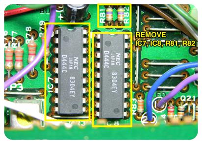
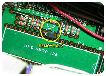
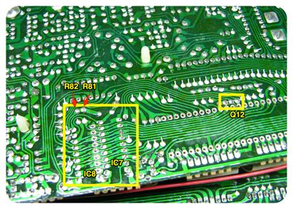
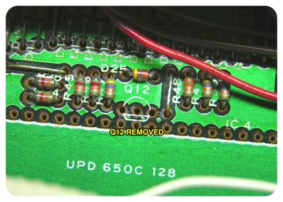
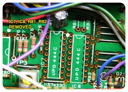
18 REMOVING MEMORY CIRCUITS Because the Quicksilver 606 CPU uses onboard EEPROM for memory storage, the old memory chips are no longer needed. You must remove IC7, IC8, Q12, R82 and R81 to create a location to install the additional parts needed for PATTERN GROUP LED modification. Use the same desoldering techniques as described for removing the CPU. Any patterns or tracks stored in the old 606 memory chips cannot be loaded by the Quicksilver 606 CPU, remember to backup any patterns or tracks you wish to keep! Quicksilver 606 CPU 16 Installation Guide
19 Quicksilver 606 CPU 17 Installation Guide
20 Quicksilver 606 CPU 18 Installation Guide
21 Quicksilver 606 CPU 19 Installation Guide

22 MODIFYING PATTERN GROUP LEDS The original TR-606 pattern group LEDs were only used to display limited information, and could only light one or the other of the two LEDs at one time. With the Quicksilver 606 CPU, the pattern group LEDs are used for many different modes, and require individual control circuitry. To enable the CPU to control the LEDs individually, some extra wires need to be put in place after removing the memory chip circuitry. The two wires will run from the switchboard PCB to the main PCB. REMOVING PATTERN GROUP LED RESISTORS Two existing resistors and a capacitor must be removed from the switchboard PCB to make room for the new resistors and wires. They are labeled as C402, R426 and R427 on the PCB. NOTE: If you are looking at the resistors on the TR-606 schematics, there is a mistake on the schematic diagram. The diodes D430 and D429 are incorrectly labeled on the schematic, D429 is actually D430 and vice versa. Quicksilver 606 CPU 20 Installation Guide

23 Quicksilver 606 CPU 21 Installation Guide

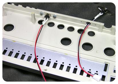
24 Two wires must now be installed in the locations left open by the removed components. Make sure that the wires are long enough to allow the switchboard to be moved, and to allow the case to be reassembled. Quicksilver 606 CPU 22 Installation Guide

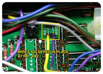
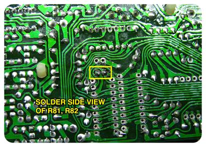
25 One wire should connect from the location of R426 on the switchboard PCB to the location of R82 on the main PCB. The pad for R426 should be the junction of R426 and the base of Q413. The pad for R82 should be the junction of R82 and pin16 of IC8-IC7. The second wire should connect from the location of R427 on the switchboard PCB to the location of R81 on the main PCB. The pad for R427 should be the junction of R427 and the base of Q414. The pad for R81 should be the junction of R81 and pin17 of IC8-IC7. NOTE: Make sure to use the correct pad of each resistor location! Please see the photos for clarification. Quicksilver 606 CPU 23 Installation Guide
26 Quicksilver 606 CPU 24 Installation Guide

27 Quicksilver 606 CPU 25 Installation Guide
28 INSTALLING THE QUICKSILVER 606 CPU Now that the old CPU has been removed and the pattern group LED circuit modified, the new Quicksilver 606 CPU can be soldered into place. We do not recommend using an IC socket because the Quicksilver 606 CPU has a USB jack that could interfere with the switchboard if it sits too high in the machine (with a socket). Quicksilver 606 CPU 26 Installation Guide

29 NOTE: We have seen some machines that have replacement switchboards installed that use a socket and header for the switchboard wiring. This socket does not allow enough room for the Quicksilver 606 CPU to be placed on the PCB. To install the Quicksilver 606 CPU, the switchboard wiring may need to be replaced with the original ribbon cable connectors or the socket/header removed and the wiring soldered directly to the PCB. Quicksilver 606 CPU 27 Installation Guide

30 The Quicksilver 606 CPU should be carefully placed in the location of the old CPU. The right angle headers should point toward the rear of the machine. Please see the photo for proper orientation. Quicksilver 606 CPU 28 Installation Guide


31 After verifying that the Quicksilver 606 CPU is properly placed on the PCB, carefully flip the PCB over and solder the CPU into place. We usually tack one pin on the corner with solder and then check to make sure that the CPU is seated properly on the board before soldering the remaining pins. Remember to remove any remaining flux after completion. Quicksilver 606 CPU 29 Installation Guide
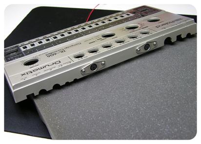
32 If you have not chosen the MIDI or USB options, then you can now jump to the instructions for case reassembly. OPTIONAL: MIDI JACK INSTALLATION If you have chosen to include MIDI input or output, then you will need to mount sockets to the case. Optionally, the DIN Sync jack can be repurposed as a MIDI input if it is no longer needed. This method does not require any holes to be drilled in the 606 case. If you choose to use the DIN Sync jack instead of drilling holes in the case, then you can replace DIN sync with a MIDI input, but you will no longer be able to sync to/from external DIN sync devices. Various other methods of connecting MIDI input or output can be devised and explored by the installer. Please see the MIDI wiring diagram towards the end of this document for details on MIDI input output pins from the CPU. We recommend mounting the mini DIN panel sockets on the back of the machine between the ACcent / BassDrum volume knobs and between the CYmbal / O.C.Hihat volume knobs. See photo for an example of mounting the sockets. Quicksilver 606 CPU 30 Installation Guide

33 To cut holes in the back of the case, we use a "computer controlled" milling machine, which gives a precise cut. We have included a template diagram of the hole placement at the end of this document. Quicksilver 606 CPU 31 Installation Guide
34 Quicksilver 606 CPU 32 Installation Guide


35 Plug the two and three wire leads into the corresponding header pins on the Quicksilver 606 CPU before reassembling the case. Quicksilver 606 CPU 33 Installation Guide
36 Quicksilver 606 CPU 34 Installation Guide

37 OPTIONAL: USB JACK INSTALLATION If you choose to mount the USB dongle, you will need to find a good place to put the USB socket. We recommend placing it inside the battery compartment, that way there isn't a large hole drilled in the case. The USB socket is used for USB-MIDI communication and Quicksilver 606 OS updates, which should happen occasionally. Quicksilver 606 CPU 35 Installation Guide


38 A small opening is needed for the USB wire to enter the battery compartment. We recommend cutting a small notch on the interior wall of the case, rather than in the plastic battery gutter. The gutter plastic is fragile and would lose some structural integrity if cut. Quicksilver 606 CPU 36 Installation Guide

39 After the creating the opening, plug the USB dongle into the Quicksilver 606 CPU. Be careful to feed the USB cable through the opening before closing the case. Quicksilver 606 CPU 37 Installation Guide

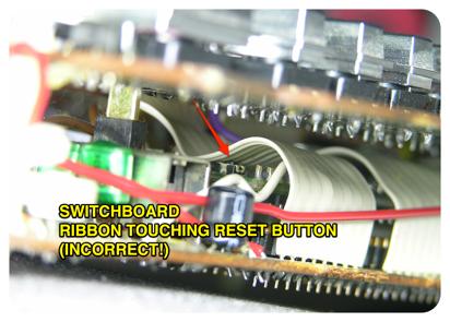
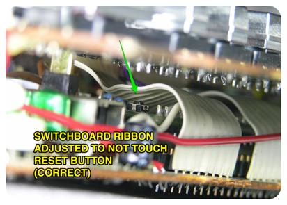
40 REASSEMBLING THE CASE Now that the Quicksilver 606 CPU is installed and all of the additional cables are in place, you will need to carefully route the cables and close the case. First, replace the switchboard PCB onto the plastic standoffs. Align the switchboard on the three standoffs and push gently on the switchboard PCB until the plastic clips engage on the edge of the holes. Make sure that the switchboard wires are routed neatly over the Quicksilver 606 CPU. NOTE: Check to make sure that the switchboard wiring does not accidentally press down on the small reset switch mounted on the CPU. By default it is likely that the wire touches this switch when the switchboard is placed back on the plastic PCB stands. If the ribbon cable is touching the switch, gently bend the ribbon cable slightly upwards to clear the reset switch. See photos for details. Quicksilver 606 CPU 38 Installation Guide
41 Quicksilver 606 CPU 39 Installation Guide
42 If installed, the optional MIDI leads will be attached to the top of the case and the CPU. Carefully place the MIDI leads so they do not interfere with any of the knobs and do not get pinched between any of the case mounting posts. You will also need to route the MIDI wires carefully under the small PCB that sits above the rotary switches. When plugging the two-pin header for MIDI IN, it may be a tight fit next to the plastic standoff for the small PCB above the rotary switches. Quicksilver 606 CPU 40 Installation Guide

43 Now place the case top together with the PCB and verify that the MIDI leads are neatly inside the case. If you are having trouble getting the case and PCB together, it sometimes helps to remove the small knobs from the potentiometers so that the MIDI sockets can easily fit between the potentiometer shafts during assembly. They can be put back in place after the case is assembled. Quicksilver 606 CPU 41 Installation Guide

44 Reattach the battery gutter, which holds the PCB in the top case. If the USB dongle is installed, verify that the dongle is placed correctly in the battery area. Quicksilver 606 CPU 42 Installation Guide


45 With the machine facing down, place the case bottom onto the PCB, making sure that the battery wires and USB dongle are located correctly. It is easy to get the battery wires pinched between the case mounting posts, so if the case does not seem to close tightly, check for pinched wires. Quicksilver 606 CPU 43 Installation Guide
46 Once the case is together correctly, the screws can be put back in place and tightened. We do not recommend tightening the screws any more than necessary to hold the case snugly. The plastic screws posts tend to crack with age and over tightening. Installation is now complete! Quicksilver 606 CPU 44 Installation Guide
47 TESTING THE CPU To test the Quicksilver 606 CPU for the first time, connect a good regulated 9v power supply and an audio output device. Now, switch on the TR-606 power switch. The 606 should display a chase LED as the machine boots. The machine will come with all memory initialized, so all patterns and tracks will contain blank data. For more in-depth usage instructions, please see the Quicksilver 606 CPU User Guide. Quicksilver 606 CPU 45 Installation Guide


48 MIDI SOCKET LABELS If you purchased the MIDI dongle option, you should have received a small sticker sheet that has labels for the MIDI INPUT and MIDI OUTPUT sockets. Use scissors to cut the stickers as desired and place on the case above the MIDI sockets. Quicksilver 606 CPU 46 Installation Guide

49 STORING THE OLD CPU The shipping box makes a great container for keeping your original CPU safe! Quicksilver 606 CPU 47 Installation Guide
50 MIDI WIRING DIAGRAM MIDI OUTPUT MIDI INPUT REAR OF 5-PIN MIDI SOCKET REAR OF 5-PIN MIDI SOCKET REAR OF 6-PIN MINI-DIN SOCKET 6 5 REAR OF 6-PIN MINI-DIN SOCKET MIDI OUT MIDI IN Quicksilver 606 CPU 48 Installation Guide
51
52 Quicksilver 606 Installation Guide Copyright 2014 Social Entropy LLC v1.02
Written By: Walter Galan
 Replace a cracked screen on your iphone 4S. Written By: Walter Galan ifixit CC BY-NC-SA www.ifixit.com Page 1 of 32 INTRODUCTION Use this guide to replace the screen on your iphone 4S. After successfully
PARTS LIST 1 x PC Board 36 x 5mm Red LED 36 x 12mm LED Standoff 36 x NPN Transistor 36 x 10kΩ Resistor OTHER PARTS YOU MAY NEED
 PARTS LIST 1 x PC Board 36 x 5mm Red LED 36 x 12mm LED Standoff 36 x NPN Transistor 36 x 150Ω Resistor 36 x 10kΩ Resistor 17 x Mini Toggle on-off 8 x Mini Toggle (on)-off-(on) 1 x 470Ω Resistor 1 x 47µF
Populating and Installing Synthex Rev 2/3 EPROM adapter board. R Grieb 5/13/2018
 Populating and Installing Synthex Rev 2/3 EPROM adapter board. R Grieb 5/13/2018 Please read these instructions before purchasing or installing the EPROM adapter, to make sure you are comfortable performing
Emax SE SCSI Port Emax Plus Retrofit Instructions (Fl360)
") Emax SE SCSI Port Emax Plus Retrofit Instructions (Fl360) Tools needed: Exacto Knife, Vacuum Desoldering Tool, Soldering Iron, Solder, Phillips Screwdriver, Needle Nose Pliers, 1/2 Nut Driver, 5/8 and
Emax SE SCSI Port Emax Plus Retrofit Instructions (Fl360) Tools needed: Exacto Knife, Vacuum Desoldering Tool, Soldering Iron, Solder, Phillips Screwdriver, Needle Nose Pliers, 1/2 Nut Driver, 5/8 and
Casio CZ. Non volatile memory modification Installation instructions version copyright 2013 Artefacts
 Casio CZ Non volatile memory modification Installation instructions version 2.0 2017 www.artefacts.nl copyright 2013 Artefacts Introduction The Casio CZ-101 and CZ-1000 do not have a separate backup battery
Part 2: Building the Controller Board
 v3.01, June 2018 1 Part 2: Building the Controller Board Congratulations for making it this far! The controller board uses smaller components than the wing boards, which believe it or not, means that everything
SDR Cube Transceiver Online Assembly Guide
 Page 1 of 13 SDR Cube Transceiver Online Assembly Guide Detailed construction notes for building and testing the SDR Cube Kit Home Bill of Materials I/O Board Controls Board DSP Board Softrock SR-Base
Installing PRO/DGX or Pro Soloist MIDI interface. R Grieb 9/08/2017
 Installing PRO/DGX or Pro Soloist MIDI interface. R Grieb 9/08/2017 Please read these instructions before purchasing the MIDI interface, to make sure you are comfortable performing the necessary steps.
IQ32 Upgrade Kit Assembly Instructions
 IQ32 Upgrade Kit Assembly Instructions Jim Veatch WA2EUJ September 17, 2018 TABLE OF CONTENTS 1. INTRODUCTION... 3 2. IQ-32 UPGRADE KIT INVENTORY... 4 3. PREPARING THE RS-HFIQ AND SIDE PANELS... 6 4. CONNECTING
A how-to guide for replacing the DJI Phantom 4 body shell. *Replacing the body shell could also be used as a tear-down guide. Written By: GotMac
 A how-to guide for replacing the DJI Phantom 4 body shell. *Replacing the body shell could also be used as a tear-down guide. Written By: GotMac ifixit CC BY-NC-SA www.ifixit.com Page 1 of 15 INTRODUCTION
Elecraft W1 SWR/Wattmeter Enclosure by W8FGU
 Elecraft W1 SWR/Wattmeter Enclosure by W8FGU The W1 enclosure is made of Lexan, a polycarbonate, which is very strong. It also has a UV blocking coating on one side and was assembled carefully with this
RC Tractor Guy Controller V2.1 Assembly Guide
 RC Tractor Guy Controller V. Assembly Guide Features 0 Push button inputs Dual axis thumb sticks with built-in push button Rotary encoders with built-in push button MCU Socket to suit Meduino Mega 560
GPIB-232CT-A IBCL EPROM Installation Guide
 NATIONAL INSTRUMENTS The Software is the Instrument Installation Guide GPIB-232CT-A IBCL EPROM Installation Guide This guide describes how to replace the factory-installed EPROM that comes with your GPIB-232CT-A.
Phase Loss Protection Upgrade. Phase Loss Protection Upgrade. In this bulletin:
 Phase Loss Protection Upgrade In this bulletin: Introduction... 2 Purpose... 2 General... 2 Applicability... 2 HD3070 Phase Loss Protection Upgrade Kit Parts... 2 Preparation... 4 Install the Phase Loss
Written By: Sam Lionheart
 iphone 5s Earpiece Speaker Replacement Replace the earpiece speaker in an iphone 5s. Written By: Sam Lionheart ifixit CC BY-NC-SA www.ifixit.com Page 1 of 22 INTRODUCTION Use this guide to replace a broken
Phi-panel backpack assembly and keypad options Dr. John Liu 12/16/2012
 Phi-panel backpack assembly and keypad options Dr. John Liu 12/16/2012 1. Introduction:... 3 Currently available:... 3 2. Backpack assembly... 4 3. Connecting to a keypad... 6 4. Rotary encoder keypads...
Pacific Antenna Two Tone Generator
 Pacific Antenna Two Tone Generator Description Our Two Tone Generator kit provides two non-harmonic, sine wave signals for testing audio circuits Outputs of approximately 700Hz and 1900Hz and the combination
iphone 3G Headphone Jack Replacement Replace a broken audio port in an iphone 3G. Written By: irobot ifixit CC BY-NC-SA
 iphone 3G Headphone Jack Replacement Replace a broken audio port in an iphone 3G. Written By: irobot ifixit CC BY-NC-SA www.ifixit.com Page 1 of 18 INTRODUCTION No audio? Replace the headphone jack! TOOLS:
KNIGHT S GALLOP ALGO-RHYTHMIC GENERATOR BUILDING GUIDE
 KNIGHT S GLLOP LGO-RHYTHMIC GENERTOR UILDING GUIDE Table of Contents 01. Components List + Tools 02. PC Sides 03. Important Note 04. Top PC ssembly 04_1. Diode 1N4148 04_2. Laying Resistors 04_3. Zenner
UF-3701 Power Board Construction Guide
 Page 1/5 Soldering and Part Placement See the Chapter 3 of the MIT 6270 Manual for information on electronic assembly, including soldering techniques and component mounting. Construction Information All
[Note: Power adapter is not included in the kits. Users need to prepare a 9 12 V ( >300mA capacity ) DC power supply]
![[Note: Power adapter is not included in the kits. Users need to prepare a 9 12 V ( >300mA capacity ) DC power supply]](/thumbs/76/74094055.jpg "[Note: Power adapter is not included in the kits. Users need to prepare a 9 12 V ( >300mA capacity ) DC power supply]") 062 LCD Oscilloscope Assembly Notes Applicable Models: 06203KP, 06204KP DN062-18v02 Important Notes 1. Some components shown in the schematic and PCB layout are for options or adjustments. They do not
062 LCD Oscilloscope Assembly Notes Applicable Models: 06203KP, 06204KP DN062-18v02 Important Notes 1. Some components shown in the schematic and PCB layout are for options or adjustments. They do not
imac Intel 27" Retina 5K Display CPU Replacement
 imac Intel 27" Retina 5K Display CPU Replacement Replace or upgrade the CPU in your imac Intel 27" Retina 5K Display. Written By: Sam Lionheart ifixit CC BY-NC-SA www.ifixit.com Page 1 of 36 INTRODUCTION
A TCP/IP network CAT 5 cable If the network is faster than 10baseT a switching hub will be needed Static IP address
 Requirements A TCP/IP network CAT 5 cable If the network is faster than 10baseT a switching hub will be needed Static IP address Power Up A Reader with an Ethernet adaptor installed and the network cable
RSL PSM-2 Power Supply Module Project: Modifying a FlatCap2
 RSL PSM-2 Power Supply Module Project: Modifying a FlatCap2 Dear Do-It-Yourselfer, The stock FlatCap2 is less than a stellar performer. Used with a CD5 CD player, for example, it gives flabby bass control,
BMC24. MIDI TO GATE CONVERTER DOCUMENTATION. This documentation is for use with the "Euro Style" bottom board.
 BMC24. MIDI TO GATE CONVERTER DOCUMENTATION. This documentation is for use with the "Euro Style" bottom board. A. USING THE MIDI TO GATE CONVERTER B. PARTS LIST C. BUILDING INSTRUCTIONS D. SCHEMATICS Revision.
Upgrade Instructions. P/N Revision A. October Printer Terminal Holder * *
 Upgrade Instructions P/N 96-08-0 Revision A October 000 480 Printer Terminal Holder P/N 96-08-0 Revision A *96080* Instructions This terminal holder connects the INTERMEC R 600 Series and 700 Series Computers
Tubbutec Sumtiple Kit Version Construction Manual
 Tubbutec Sumtiple Kit Version Construction Manual This document describes the construction of the Sumtiple Kit. The following parts are included: 1x Sumtiple PCB with SMD-Parts already soldered 1x Front
Written By: Ben Eisenman
 iphone 3GS Rear Panel Replacement Replace a broken rear case on your iphone 3GS. Written By: Ben Eisenman ifixit CC BY-NC-SA www.ifixit.com Page 1 of 22 INTRODUCTION The plastic rear half of the iphone.
MAKE SURE TO TURN OFF YOUR TRS-80 BEFORE ATTACHING NEWKEY/80 KEYBOARD RIBBON CABLE AND POWER CABLE.
 NEWKEY/80 User's Guide v1.4 TRS80 Keyboard Adapter 12/10/2018 Plaid Vest Software, LLC. www.plaidvest.com/newkey80 IMPORTANT NOTE: MAKE SURE TO TURN OFF YOUR TRS-80 BEFORE ATTACHING NEWKEY/80 KEYBOARD
Construction Construction Instructions
 Semi-Virtual Diskette SVD Construction Construction Instructions PCB version 2.0 September 2004 Eric J. Rothfus Table of Contents Table of Contents... i Parts List...1 Construction Overview...5 PCB Construction...
The GENIE Light Kit is ideal for introducing simple lighting projects, such as an electronic die, a wearable badge or a night-time warning system.
 Introduction 1 Welcome to the GENIE microcontroller system! The GENIE Light Kit is ideal for introducing simple lighting projects, such as an electronic die, a wearable badge or a night-time warning system.
Elecraft K3 KPA3 Power Connector Replacement Revision B, June 30, 2017 Copyright 2017, Elecraft, Inc. All Rights Reserved
 Introduction Elecraft K3 KPA3 Power Connector Replacement Revision B, June 30, 2017 Copyright 2017, Elecraft, Inc. All Rights Reserved The connectors furnishing high current to the KPA3 module have failed
ipod Classic Headphone Jack & Hold Switch Replacement
 ipod Classic Headphone Jack & Hold Switch Replacement Replace Headphone Jack & Hold Switch to fix no audio and/or no unlock Written By: irobot ifixit CC BY-NC-SA www.ifixit.com Page 1 of 22 INTRODUCTION
A Backlighted LCD for your K1
 A Backlighted LCD for your K1 (K1BKLTKIT) Tom Hammond - NØSS, July 27, 2006 Rev C Thanks to Wayne Burdick, N6KR for suggesting this implementation of backlighting the K1 display. APPLICABILITY This modification
imac Intel 27" EMC 2639 Hard Drive
 imac Intel 27" EMC 2639 Hard Drive Replacement Replace the Hard Drive in your imac Intel 27" EMC 2639. Written By: Walter Galan ifixit CC BY-NC-SA www.ifixit.com Page 1 of 26 INTRODUCTION Replacing the
Canon EOS Rebel T2i Top Cover Replacement
 Canon EOS Rebel T2i Top Cover Replacement Replacing the top piece of a Canon T2i (550D). In my case, I had a broken hot-shoe, but as most controls on this camera are built into the same part, this repair
BS2p40tm OEM Module. Surface mount/through hole kit By Robert L. Doerr. Manual Revision.5
 BS2p40tm OEM Module Surface mount/through hole kit 2006 By Robert L. Doerr Manual Revision.5 NOTE: The BASIC Stamp and the BS2p40 and Interpreter chip are trademarks of Parallax. This partial kit allows
Removal and Installation8
 8 Screw Types 8-4 Top Cover Assembly 8-5 Left Hand Cover 8-6 Right Hand Cover 8-10 Front Panel Assembly 8-14 Left Rear Cover 8-15 Right Rear Cover 8-16 Extension Cover (60" Model only) 8-17 Media Lever
Pacific Antenna Easy TR Switch Kit
 Pacific Antenna Easy TR Switch Kit Kit Description The Easy TR Switch is an RF sensing circuit with a double pole double throw relay that can be used to automatically switch an antenna between a separate
Replacement Instructions. Backplane PCA for the HP Router 650
 Replacement Instructions Backplane PCA for the HP Router 650 Copyright Hewlett-Packard Company 1994. All rights reserved. Publication Number 5962-8369 Edition 1, August 1994 Printed in USA This guide provides
orban FIELD ENGINEERING BULLETIN Purpose: Units Affected: Replacement Kit, Orban Part # Replacing SSM2017 Op-Amps
 orban FIELD ENGINEERING BULLETIN March 27, 2002 Orban Models: 2200, 6200, 6200S, 8200, 8282, 9200 Purpose: Due to the elimination of the SSM2017 by its manufacturer, Orban has had to choose a replacement
Universal Keying Adapter 3+
 Universal Keying Adapter 3+ The Universal Keying Adapter Version 3+ kit will allow you to key nearly any transmitter or transceiver with a straight key, electronic keyer, computer serial or parallel port
Removing and Replacing Parts
 Removing and Replacing Parts Preparing to Work Inside the Computer Recommended Tools Screw Identification System Components Hard Drive Fixed Optical Drive Media Bay Devices Memory Modules Mini PCI Card
TIME WIZARD MULTI CLOCK DIVIDER BUILDING GUIDE
 TIME WIZARD MULTI CLOCK DIVIDER BUILDING GUIDE Table of Contents 0. Components List + Tools 0. PCB Sides 03. PCB Assembly 04_. Diode N448 04_. Laying Resistors 04_3. Capacitors 04_4. Quartz 04_5. 78L05
EMC 10/4 "CE" Mechanical Upgrade Procedure
 EMC 10/4 "CE" Mechanical Upgrade Procedure Kit Part Number: 009663-01 This procedure upgrades a non-ce compliant machine to the mechanical requirements of a CE compliant machine. Properly upgraded machines
FITTING INSTRUCTIONS
 & This option connects a GL3000 or GL3300 console as a channel expander to a second console with just one or two interconnecting cables. Kit Part No: GL3000-SL1 Single option to install SYS-LINK to one
Assembly Instructions (8/14/2014) Your kit should contain the following items. If you find a part missing, please contact NeoLoch for a replacement.
 Your kit should contain the following items. If you find a part missing, please contact NeoLoch for a replacement.") NeoLoch NLT-28P-LCD-5S Assembly Instructions (8/14/2014) Your kit should contain the following items. If you find a part missing, please contact NeoLoch for a replacement. Kit contents: 1 Printed circuit
NeoLoch NLT-28P-LCD-5S Assembly Instructions (8/14/2014) Your kit should contain the following items. If you find a part missing, please contact NeoLoch for a replacement. Kit contents: 1 Printed circuit
Written By: Andrea Giannone
 How to Fix iphone 4S Wi-Fi Grayed Out Use this guide to permanently fix an "unclickable" grayed out Wi-Fi button in the iphone 4s. Written By: Andrea Giannone ifixit CC BY-NC-SA www.ifixit.com Page 1 of
Replacement Keyswitch Assembly
 Installation Instructions Replacement Keyswitch Assembly (Catalog No. 2711E-NKSW1) Applicable Terminals Use this replacement keyswitch with PanelView Terminals 2711-KA1, -KC1, -TA1, -TC1, -TA4, -TC4 and
Replace the edrive TINI Module and Battery
 Product All edrive Configurations Special Information INFORMATION: This service bulletin is for informational purposes only. It is intended for use by Northrop Grumman Cutting Edge Optronics (NG CEO) employees
Assembly Guide. LEDs. With these assembly instructions, you can easily build your own SWT16. All required components are included in this kit.
 Assembly Guide With these assembly instructions, you can easily build your own SWT16. All required components are included in this kit. You need the following tools: soldering iron, wire cutter and solder.
Insert the male, 90 angled, 2x10 connectors into the corresponding 2x10 sockets and put them in place, flat under the PCB. Solder.
 MC624 Assembly guide Safety warning The kits are main powered and use potentially lethal voltages. Under no circumstance should someone undertake the realisation of a kit unless he has full knowledge about
How to add a Second Drive to a Mac mini (2012) using the OWC Data Doubler SSD/2.5 Installation Kit
 using the OWC Data Doubler SSD/2.5 Installation Kit") Instructional Video Series How to add a Second Drive to a Mac mini (2012) using the OWC Data Doubler SSD/2.5 Installation Kit Skill Level: Challenging Time to Complete: Approximately 45 Minutes Required
Instructional Video Series How to add a Second Drive to a Mac mini (2012) using the OWC Data Doubler SSD/2.5 Installation Kit Skill Level: Challenging Time to Complete: Approximately 45 Minutes Required
dual bipolar voltage controlled step sequencer DIY ASSEMBLY MANUAL v1.03
 dual bipolar voltage controlled step sequencer DIY ASSEMBLY MANUAL v1.03 Contents Contents... 2 Introduction... 3 Part Sourcing Notes for Non Kit Builders... 3 Eurorack Kit Assembly... 4 Resistors and
Reflowing Xbox 360 Motherboard
 Reflowing Xbox 360 Motherboard Reflow the solder on your Xbox 360's motherboard. Written By: Andrew Bookholt ifixit CC BY-NC-SA www.ifixit.com Page 1 of 31 INTRODUCTION Use this guide to reflow the solder
SharpSky Focuser Construction. SharpSky Focuser. Construction Document V st December 2012 Dave Trewren 1
 SharpSky Focuser Construction Document V0.12 1st December 2012 Dave Trewren 1 Contents 1 General... 3 1.1 Change Record... 3 1.2 References... 3 2 Introduction... 5 3 SharpSky driver installation... 5
Written By: Sam Lionheart
 iphone 5c Front Panel Replacement Replace the Front Panel on your iphone 5c. Written By: Sam Lionheart ifixit CC BY-NC-SA www.ifixit.com Page 1 of 24 INTRODUCTION For an easier repair, use our fix kit
imac Intel 21.5" EMC 2389 Stand Replacement
 imac Intel 21.5" EMC 2389 Stand Replacement Replace a broken or cosmetically unappealing stand on the imac 2389 21.5 Written By: Aaron Cooke ifixit CC BY-NC-SA www.ifixit.com Page 1 of 30 INTRODUCTION
Dell Latitude C800 Service Manual
 Dell Latitude C800 Service Manual Dell Latitude C800 Service Manual Before You Begin Preparing to Work Inside the Computer Recommended Tools Screw Identification Removing and Replacing Parts System Components
ipod Touch 4th Generation 30 Pin Dock Connector Replacement
 ipod Touch 4th Generation 30 Pin Dock Connector Replacement Learn how to replace the 30 pin dock connector on an ipod touch 4th generation. Written By: Gabe Keehn ifixit CC BY-NC-SA www.ifixit.com Page
Written By: Sam Lionheart
 iphone SE Logic Board Replacement Use this guide to replace a faulty logic board in your iphone SE. Written By: Sam Lionheart ifixit CC BY-NC-SA www.ifixit.com Page 1 of 27 INTRODUCTION Use this guide
TKEY-1. CW touch key. (no electromechanical contacts) Assembly manual. Last update: June 20,
 Assembly manual. Last update: June 20,") TKEY-1 CW touch key (no electromechanical contacts) Assembly manual Last update: June 20, 2017 ea3gcy@gmail.com Updates and news at: www.ea3gcy.com Thanks for constructing the TKEY-1A CW touch key Have
TKEY-1 CW touch key (no electromechanical contacts) Assembly manual Last update: June 20, 2017 ea3gcy@gmail.com Updates and news at: www.ea3gcy.com Thanks for constructing the TKEY-1A CW touch key Have
Chapter 2 Working Inside Desktop Computers and Laptops
 Chapter 2 Working Inside Desktop Computers and Laptops TRUEFALSE 1. When disassembling a computer, it's okay to stack circuit boards on top of each other as long as you follow ESD protection rules. (A)
Cherub Chorus. Wobbly fun based on Rick Holt s Little Angel
 Cherub Chorus Wobbly fun based on Rick Holt s Little Angel Contents of this document are 2015 Pedal Parts Ltd. No reproduction permitted without the express written permission of Pedal Parts Ltd. All rights
OpenSprinkler v2.2u Build Instructions
 OpenSprinkler v2.2u Build Instructions (Note: all images below are 'clickable', in order for you to see the full-resolution details. ) Part 0: Parts Check Part 1: Soldering Part 2: Testing Part 3: Enclosure
Written By: Walter Galan
 imac Intel 21.5" EMC 2428 CPU Replacement Replace the CPU in your imac Intel 21.5" EMC 2428. Written By: Walter Galan ifixit CC BY-NC-SA www.ifixit.com Page 1 of 33 INTRODUCTION Use this guide to upgrade
Written By: Sam Lionheart
 iphone 5s Lightning Connector Replacement Remove the Lightning connector/headphone jack assembly from your iphone 5s. Written By: Sam Lionheart ifixit CC BY-NC-SA www.ifixit.com Page 1 of 26 INTRODUCTION
Colecovision 5v Memory Mod Installation
 Colecovision 5v Memory Mod Installation The Colecovision suffers from common failure points: the power supply, power switch, and 4116 DRAM. The power supply suffers from poor soldering, the power switch
TD-700 FLUOROMETER SERVICE MANUAL
 TD-700 FLUOROMETER SERVICE MANUAL July 1996 CONTENTS Page Section 1 INTRODUCTION 2 Section 2 PRELIMINARY CHECKS 3 Section 3 TROUBLESHOOTING GUIDE 5 A. Lamp (Fluorescent) 5 B. Lamp Heater 7 C. Fan 8 D.
TABLE OF CONTENTS SECTION 1 TABLETOP CONFIGURATION SECTION 2 TABLETOP CONFIGURATION ACCESSORIES SECTION 3 SLIDE CONFIGURATION
 S6 USER S MANUAL TABLE OF CONTENTS SECTION 1 TABLETOP CONFIGURATION SECTION 2 TABLETOP CONFIGURATION ACCESSORIES SECTION 3 SLIDE CONFIGURATION SECTION 4 SLIDE CONFIGURATION ACCESSORIES SECTION 5 RACK MOUNT
E2460GS Oscilloscope Upgrade Kit
 Installation Instructions for E2460GS Oscilloscope Upgrade Kit Agilent 1670G-Series Logic Analyzers This kit upgrades either the Agilent Technologies 1670G, Agilent 1671G, Agilent 1672G, or the Agilent
imac Intel 21.5" Retina 4K Display (2017) RAM
 RAM") imac Intel 21.5" Retina 4K Display (2017) RAM Replacement Learn how to replace or upgrade the RAM in your 2017 Retina 4K imac. Written By: Evan Noronha ifixit CC BY-NC-SA www.ifixit.com Page 1 of 38 INTRODUCTION
imac Intel 21.5" Retina 4K Display (2017) RAM Replacement Learn how to replace or upgrade the RAM in your 2017 Retina 4K imac. Written By: Evan Noronha ifixit CC BY-NC-SA www.ifixit.com Page 1 of 38 INTRODUCTION
Presario 1200 Series Models: XL101-XL113, XL115, XL118-XL127. This section explains the removal and replacement procedures for the 1200XL unit.
 Removal Sequence Presario 1200 Series This section explains the removal and replacement procedures for the 1200XL unit. Serial Number Location Report the unit s serial number 1 to Compaq when requesting
ENCORE /ST G4. Processor Upgrade Card for Power Mac G4 AGP Graphics. Quick Start Guide for Encore/ST G4
 ENCORE /ST G4 Processor Upgrade Card for Power Mac G4 AGP Graphics Quick Start Guide for G4 Power Mac and Operating System Compatibility This G4 processor upgrade is compatible only with Power Mac G4 AGP
Samsung Galaxy S6 Daughterboard
 Samsung Galaxy S6 Daughterboard Replacement Replace the daughterboard on a Samsung Galaxy S6. Written By: Dante Mazzanti ifixit CC BY-NC-SA www.ifixit.com Page 1 of 28 INTRODUCTION Use this guide to replace
HP Pavilion dv7-6c90us Cooling fan Replacement
 HP Pavilion dv7-6c90us Cooling fan Replacement This guide will walk you through the process of replacing the cooling fan in an HP Pavilion dv7 laptop. Written By: Angelina Clayton ifixit CC BY-NC-SA www.ifixit.com
Electronic Balance Ionizer STABLO-AP Service Manual
 321-78209 Jan. 2016 Electronic Balance Ionizer STABLO-AP Service Manual Analytical & Measuring Instruments Division This page is intentionally left blank. Table of Contents 1. Precautions for Troubleshooting...
Replacing the PanelMate Power Pro 1785 Series, PanelMate epro 7585x-8 and 7685x-8 Series Backlight Assembly
 Replacing the PanelMate Power Pro 1785 Series, PanelMate epro 7585x-8 and 7685x-8 Series Assembly Introduction The Replacement Kit provides a replacement backlight for the PanelMate Power Pro 1785 Series,
K8099 NIXIE CLOCK. * optional enclosure TKOK19 (black) - TKOK17 (white) ** optional plexiglass enlcosure B8099 ILLUSTRATED ASSEMBLY MANUAL
 - TKOK17 (white) ** optional plexiglass enlcosure B8099 ILLUSTRATED ASSEMBLY MANUAL") Total solder points: 230 + 74 Difficulty level: beginner 1 2 3 4 5 advanced NIXIE CLOCK K8099 ** * A unique combination of both vintage and modern electronics ILLUSTRATED ASSEMBLY MANUAL H8099IP-1 * optional
Total solder points: 230 + 74 Difficulty level: beginner 1 2 3 4 5 advanced NIXIE CLOCK K8099 ** * A unique combination of both vintage and modern electronics ILLUSTRATED ASSEMBLY MANUAL H8099IP-1 * optional
WEASEL N/B MAINTENANCE
 2. System Assembly & Disassembly 2.1 System View 2.1.1 Front View ❶ Microphone Connector ❷ Audio Input Connector ❸ Audio Output Connector ❹ Top Cover Latch ❹ ❶ ❸ ❷ 2.1.2 Left-Side View ❶ VGA Port ❷ S-Video
OpenSprinkler v2.1u Build Instructions
 OpenSprinkler v2.1u Build Instructions (Note: all images below are 'clickable', in order for you to see the full-resolution details. ) Part 0: Parts Check Part 1: Soldering Part 2: Testing Part 3: Enclosure
Dell Inspiron XPS and Inspiron 9100 Service Manual
 Dell Inspiron XPS and Inspiron 9100 Service Manual Dell Inspiron XPS and Inspiron 9100 Service Manual Before You Begin Memory Module, Mini PCI Card, and Devices System Components Subwoofer Bluetooth Card
ASSET LGA1366 Top-side Probe
 ASSET LGA1366 Top-side Probe (Manual version 1.1) For gaining test access to the debug port of Intel processors that are designed for use in LGA1366 Sockets (Socket B). These include the Intel Core i7
Dell Inspiron N5110 Service Manual
 Dell Inspiron N5110 Service Manual Regulatory model: P17F Regulatory type: P17F001 Notes, Cautions, and Warnings NOTE: A NOTE indicates important information that helps you make better use of your computer.
The Basic Counter. Hobby Electronics Soldering Kit. Instruction Guide
 The Basic Counter Hobby Electronics Soldering Kit Instruction Guide TM For the best outcome, follow each step in order. We recommend reading this guide entirely before you get started. Tools required:
Little Screamerv2.0. Stripped-back, bufferless Tube Screamer
 Little Screamerv2.0 Stripped-back, bufferless Tube Screamer Contents of this document are 2016 Pedal Parts Ltd. No reproduction permitted without the express written permission of Pedal Parts Ltd. All
SNA KIT Assembly Guide
 SNA KIT Assembly Guide Ver 0.8 April 2015 Note: Many references still exist to the SNA Kit s predecessor (NAT Kit). Also, the parts and additional steps used to make the NAT an SNA have not yet been shown
Written By: Andrew Optimus Goldberg
 iphone 5 Rear-Facing Camera Replacement Remove the rear-facing 8 MP isight camera from your iphone 5 Written By: Andrew Optimus Goldberg ifixit CC BY-NC-SA www.ifixit.com Page 1 of 26 INTRODUCTION Use
Replacing the RAID Battery Backup Unit Assembly on Series 3 FireSIGHT 3500 Defense Centers, Version 5.x
 Replacing the RAID Battery Backup Unit Assembly on Series 3 FireSIGHT 3500 Defense Centers, Version 5.x Last Updated: December 4, 2014 Use these instructions to replace the RAID battery backup unit (BBU)
Electronics Construction Manual
 Electronics Construction Manual MitchElectronics 2018 Version 1 07/05/2018 www.mitchelectronics.co.uk CONTENTS Introduction 3 How To Solder 4 Resistors 5 Capacitors 6 Diodes and LEDs 7 Switches 8 Transistors
Cutter Option Installation Instructions
 This kit includes the parts and documentation necessary to install the cutter option on the Zebra XiII, XiIII, and XiIIIPlus-Series printers. NOTE: The Cutter Option is not available for the 96XiIII. Adding
3 pyro output datalogger altimeter with an ATmega 328 microcontroller Kit assembly instructions
 3 pyro output datalogger altimeter with an ATmega 328 microcontroller Kit assembly instructions Version date Author Comments 1.0 29/05/2013 Boris du Reau Initial version Rocket Type Micro-max Model Mid
How to Assemble a Desktop PC
 How to Assemble a Desktop PC By Taylor Koch iii Table of Contents Introduction to Building a Desktop PC... 1 Preparation and Precautions... 3 PC Parts... 3 Basic Tools... 3 Safety Precautions... 3 Installing
MacBook Core 2 Duo Clutch Cover
 MacBook Core 2 Duo Clutch Cover Replacement Replace the clutch cover on your MacBook Core 2 Duo. Written By: Ben Eisenman ifixit CC BY-NC-SA www.ifixit.com Page 1 of 29 INTRODUCTION Replace the curved
Welch Allyn Connex Vital Signs Monitor 6000 Power Supply Replacement
 Welch Allyn Connex Vital Signs Monitor 6000 Power Supply Replacement Replace the power supply in a 6000 series Welch Allyn Connex Vital Signs Monitor. Written By: Sam Lionheart ifixit CC BY-NC-SA www.ifixit.com
Post Tenebras Lab. Written By: Post Tenebras Lab
 Post Tenebras Lab PTL-ino is an Arduino comptaible board, made entirely out of through-hole components. It is a perfect project to learn how to solder and start getting into the world of micro controllers.
Written By: Sam Lionheart
 iphone SE SIM Eject Lever Replacement Replace the SIM eject lever in an iphone SE. Written By: Sam Lionheart ifixit CC BY-NC-SA www.ifixit.com Page 1 of 22 INTRODUCTION Is your SIM card getting stuck in
Assembling the Printed Circuit Board for the EDE1200 Robot
 This board receives instructions from either a CBL2, a LabPro or (with an adapter cable) an original CBL. The board has two 595 shift registers (each providing 8 bits of on-board memory) and two EDE1200
HARMONi G3. Quick Start Guide for HARMONi G3. imac Processor/FireWire Upgrade
 HARMONi G3 imac Processor/FireWire Upgrade imac and Operating System Compatibility The HARMONi G3 imac processor/firewire upgrade is compatible only with imac 233, 266, and 333 MHz models (Revisions A-D);
edrive RAM Battery Alternate Replacement Procedure
 edrive RAM Battery Summary This technical note describes the process for replacing the TINI RAM battery with a higher capacity battery. With the edrive turned on, the external battery can be changed without