CHAPTER. General Information
|
|
|
- Austin Watson
- 5 years ago
- Views:
Transcription
1 CHAPTER 1 General Information 1
2 Introduction The DATAMAN-48XP is an intelligent high performance, PC-based universal programmer that works through your PC s parallel port. It features a 48-pin ZIF socket and supports many of the programmable chips on the market. These include CPLD, EPROM, EEPOM, Serial EEPROM, Flash memory and MCU. The D48XP has an extremely high throughput, supports both 5V and 3V devices in both Vcc and I/O. Lower voltage chips (for example 1.8V Vcc and I/O) can also be programmed through a special adapter. Device insertion and continuity checks are also part of the PC-based design. Device support updates are issued through our software, giving our customers quick and easy access to new device support without hardware upgrades. Features Universal adapter up to 48 pin The DATAMAN-48XP is designed to meet your future needs in high density Flash chips. Using the resources of your PC, it supports 32K bit up to over 1G bit memory chips without upgrading its hardware. The DATAMAN-48XP also has universal adapters that accommodate 48-pin TSOP, 44-pin PLCC, 40-pin TSOP or 32-pin TSOP packages. Each adaptor supports all the chips in a package regardless of pin swapping. This is possible due to the universal pin driver technology on the DATAMAN-48XP, eliminating the need to buy multiple adapters and saving you money. Unbeatable speed The DATAMAN-48XP s on-board intelligence reduces system overhead to a minimum. It can program Flash devices within 2.5 seconds per Mbit (for example, AMD29DL323 can be 2
3 programmed by DATAMAN-48XP within 80 seconds). An experienced operator can program thousands of high-density chips per day. Device-insertion and continuity checks No mistakes! The DATAMAN-48XP performs device-insertion and continuity checks before programming each device. It can detect poor pin contact, upside-down device insertion, incorrect position, and pin number mismatch. This function prevents expensive chip damage caused by operator error. Auto-sensing and self-programming The DATAMAN-48XP has implemented patented technology to meet mass-production requirements. When a chip is inserted into the ZIF socket, the DATAMAN-48XP will start to program automatically, the operator just needs to follow the LEDs to know when to remove the chip and insert a new one without them needing to press any keys. Project file Save and Load You can save the program configuration project to a file that contains the device selection, the buffer data, and all of the program setup options. This file can be recalled at any time for future use without having to go through the setup procedure again. This allows you to pass your design file to the production department without mistakes. Variable VCC with one or two-pass verification The DATAMAN-48XP allows users to select the verification voltage after programming is complete, e.g., Vcc +/-5%, V cc +/-10%, Vcc can range from 2V to 7.5V. Verification ensures that the chips have been properly programmed with no data retention problems. 3
4 Device support summary Over 5000 devices are currently supported on the D48XP and you can increase the chip support by downloading software updates from Normally we add more than 100 new devices in each quarter s software update. For details of updates and added device support, please visit our website: Using the DATAMAN-48XP Software Menus Accessing the menus can be done in two ways: 1. Use the mouse and click on the menu option displayed at the top of the screen. A drop-down menu will appear, and you can select your desired option by clicking on it. 2. If you do not have a mouse available, you can also use the keyboard to access the menus. Press [F10] to activate the main menu bar. Select the sub-menu that you want to use with the left and right arrow keys, and press <ENTER> to activate the sub-menu. Use the up and down arrows to select an option to execute. Press <ENTER> to execute the command. Hot keys Most of the options available on the menus can also be executed by pressing the hot key associated with that option. To see what the hot key is for a certain option, look on the menu where the option is located. If a hot key is available, it will be displayed next to the option name. 4
5 CHAPTER 2 Installation 5
6 Minimum PC System Requirements Windows 95/98/ME/2000/XP/NT 4.0 or latest (NT, need System Admin privileges to install the software). CPU: 486 and above. RAM: 8MB minimum, 32 MB recommended. HD: 16 MB of free hard disk space. Interface: D-25 connector with standard parallel port, (ECP, EPP or Bi-directional). CD ROM Drive. Installing the DATAMAN-48XP Hardware 1. Connect the power cable to the DATAMAN-48XP power socket. 2. Connect the DATAMAN-48XP to a parallel port using the cable supplied. 3. Turn the DATAMAN-48XP on. 4. The DATAMAN-48XP will perform a self test, the green LED will be on (good) if the system has passed the self test. Installing the DATAMAN-48XP Software 1. Go to My Computer and double-click the CD-ROM drive containing the D48XP CD. 2. Double click the Setup icon to begin installation. 6
7 3. Following installation, run the software by doubleclicking the DATAMAN-48XP icon. The screen will display the DATAMAN-48XP firmware version and indicate which parallel port the DATAMAN-48XP has been discovered on. Upgrading the DATAMAN-48XP Software Dataman provide official quarterly releases of the DATAMAN-48XP software which are available on our website; please download all software updates from 7


8 CHAPTER 3 Command Hierarchy 8
9 DATAMAN-48XP Command Hierarchy System command Operation command Hot Key File (ALT-F) Save Buffer ALT-S Load File ALT-L Exit ALT-X Project (ALT-J) Save Project ALT-F1 Load Project ALT-F2 Device (ALT-D) Change ALT-C Edit ALT-E Read ALT-R Blank Check ALT-B Program/Auto ALT-P Verify ALT-V Erase Ctrl-F1 Compare Ctrl-F3 Configuration ALT-G Options (ALT-O) Modify Programming Parameter F3 Device Operation Options F4 Parallel Port Selection F5 Statistics F6 Diagnostic Self Test F7 Help (ALT-H) Help Topic About 9
10 CHAPTER 4 Operation 10
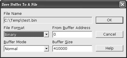
11 LED Display The DATAMAN-48XP has a three LED display to indicate the status of the socket. Read this section carefully to avoid possible damage to chips. Warning: Do not insert or remove a device from the socket while the yellow Busy LED is on! Green LED on (Good) the last operation was successful. Yellow LED on (Busy) The socket is busy; do not insert or remove devices from the ZIF socket before green LED or red LED is on. Red LED on (Error) the last operation resulted in failure. Flashing LED at 5Hz frequency. This only applies to mass production mode. The chip has passed the program and verify cycle and is waiting for the operator to remove it and insert a new one. File Commands Save Buffer to File Menu File / Save Buffer Hot key Alt-S This option is used to save the memory buffer to a file on the hard disk. Select a file using the mouse, or type a filename in the box provided. You can also type in a file extension. (e.g. *.hex) at the Name prompt. This will display all the files of the specified type. You can then select the required file to overwrite. 11
12 12
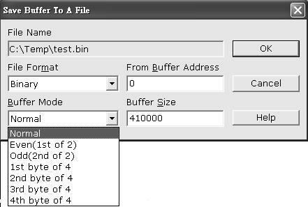
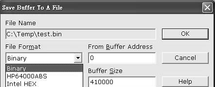
13 File name Specify the filename and destination you want to save to. File format Select the file format of your output file. To display a list of available file formats, click on the down arrow to the right of the text field. Supported file formats include: Binary, HP64000ABS, Intel Hex, MOS Technology Hex, Motorola S format, Tektronic Hex, and Straight Hex. Buffer mode This Buffer mode is to split your buffer according to the mode selection, details of the split function are explained below. Normal (default) Every byte is written to the output file. Odd Every Odd byte is written to the output file. Even Every Even byte is written to the output file. The following four options are used to write the buffer into four different files: 1st byte of 4 This writes the bytes 1,5,9,13, into the output file. 2nd byte of 4 This writes the bytes 2,6,10,14,... into the output file. 13
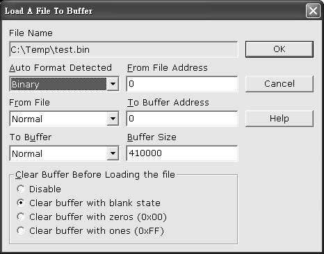
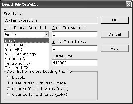
14 3rd byte of 4 This writes the bytes 3,7,11,15,... into the output file. 4th byte of 4 This writes the bytes 4,8,12,16, into the output file. From Buffer address This specifies the start address of the buffer you want to save to the file, default is from 0000h, any address (from 0h to the Max. of the buffer address can be selected) Buffer size The buffer size depends on the chip you select, for example if you select 29F010 (the buffer size will be 1Mbit which is 20000h) Load File to Buffer Menu File / Load File Hot key Alt-L This option loads a file from disk into the memory buffer. The type of files that can be loaded for a device depends on the device type. Select a file to load using the mouse, or type the filename in the box provided. You can also type in a file extension. (e.g. *.hex) at the name prompt. This will display all the files of the specified type, and you can then select the required file to load. 14
15 15
16 16
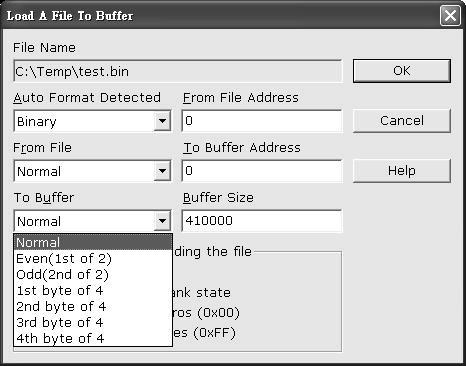
17 Filename This specifies the file name and its destination Auto Format Detected The software automatically detects the format of the file that is to be loaded. If the desired format of the file is different from the format detected, select the correct file format by moving the cursor to the selection menu and changing it to the desired file format. Available file formats include: Binary, HP64000ABS, Intel Hex, MOS Tech Hex, Motorola S format, TEK Hex, and Straight Hex. From File to Buffer This option indicates which bytes must be read from the input file. By default it will load the entire file into the buffer. You can specify that the file be loaded in the following ways: Even (loads the even bytes into the buffer), Odd (loads the odd bytes into the buffer), also 1 st byte of 4, 2 nd byte of 4, 3 rd byte of 4, 4 th byte of 4. For details, see the Save Buffer to File section of this manual. To Buffer This option indicates where the previously read byte is to be written. This enables you to build the memory buffer from several files. By default, the whole file will be loaded into the buffer. Even means the file will be loaded as every even byte in the buffer. Odd means the file will be loaded as every odd byte in the buffer. The other options are 1 st of 4 byte, 2 nd of 4 byte, 3 rd of the 4 byte, and 4 th of the 4 byte. From File Address Only a selected range of the file will be loaded into the buffer, enter the address that contains the first byte into this box, this is the starting address of the section of the file to be loaded. 17
18 To Buffer Address Starting address of the buffer to load the file into. If the data is to be copied into a specific area of the buffer, enter the starting address here. Size This box contains the buffer size. By default, it is the same size as the device selected on the DATAMAN-48XP main screen. If you want to download a file into the memory that is bigger than the active device, enter the size here (or in Options Operation Options). Clear Buffer Options Four options are available while loading data into the buffer. The default option is to clear the buffer to its blank state prior to loading data. Disable This option leaves the original buffer data unchanged, but then overwrites it with the contents of the newly loaded file. Blank state (default) This option clears the buffer to the devices blank state, (using command 00 or FF, depending on device selection), then overwrites the buffer during file loading. 0x00 First clears the buffer of its contents using command 00, then overwrites the buffer with the new file contents 0xFF First clears the buffer of its contents using command FF, then over-writes the buffer with the new file contents. 18
19 Exit Menu File / Exit Hot key Alt-X Quit the DATAMAN-48XP program 19
20 Project File Commands Save Project Menu Project / Save Project Hot key Alt-F1 This option saves the current setup of the DATAMAN-48XP software into a project file. The file includes selected devices, buffer data, operation setup, and device configuration setup. You can also attach a footnote to the project file. The project file acts as a macro, eliminating the need to go through the whole setup procedure during future programming sessions. Load Project Menu Project / Load Project File Hot key Alt-F2 This option loads the desired project file. After the project file has been loaded, you can immediately program a device using the preset data and setup functions from the Project file. Device Commands Change Device Menu Hot key Device / Change Device Alt-C 20

21 This option is used to select a new active device. It is important to select the correct device, as the algorithms used to program devices are device-specific. The following screen will appear: Figure 4.1 Screen for selecting Change Device Special note in device package and its selection In the above screen, you can find both AT89C51 and AT89C51*44 selections, the AT89C51 means this is a 40 pin DIP chip, no adapter is required and 89C51*44 means the chip is 44 pin PLCC or QFP/TQFP, adaptor required. After selecting the 89C51*44, at the bottom of the software screen will be displayed chip information and the adapter requirement. In this example, it shows SDP-UNIV-44 as the recommend adapter, it means for a 44 pin PLCC chip, you need the 44 pin PLCC universal adapter, if your chip is 44 QFP or TQFP, you will need a 44pin QFP (SDP-UNIV-44TQ) or a 44pin TQFP (SDP-UNIV-44TQ) adapter. If you have a 3 rd party 44 pin PLCC adapter that swaps the 44 21
22 pin PLCC chip into a 40 pin DIP (emulate the 44 pin PLCC as a 40 pin DIP), you can select the 89C51 in device selection and use this 3 rd party adapter. Other useful examples in device, package and adapter. 1) For example a 1M bit flash (29F010), this chip has three kinds of package, 32 pin DIP, 32 pin PLCC and 32 pin TSOP, in the DATAMAN-48XP software, it is only available in DIP package under device selection, to program a 32 PLCC chip, you will need a 32 pin DIP to 32 pin PLCC one to one pin swap adapter (PLCC ), for 32 pin TSOP, you will need a SDP-UNIV-32TS. 2) For example, a GAL22V10 chip, this chip has two packages (24 pin DIP or 28 pin PLCC), DATAMAN-48XP only shows 24 pin DIP in device selection, to program the 28 pin PLCC, a 28 pin PLCC to 24 pin DIP adapter to emulate the 24 pin DIP chip is required (PLCC ). 3) 27C128/256 EPROM chip, this chip is available in 28 pin DIP and 32 pin PLCC, to program the 32 pin PLCC, you need a 32 pin PLCC to 28 pin DIP adapter, it emulates the 32 pin PLCC as a 28 pin DIP, this adapter is PLCC ) Other SOIC chips may have the DIP/SOIC package, if the chip has the same pin out and pin count in DIP and SOIC, select the DIP with universal SOIC adapter which will program the SOIC chip (for example Pic16F73 with SDP-UNIV-28SO/300 adapter will program a 16F73 SOIC chip). 22
23 1. Select the type of device that will be the active device. Mouse Click on All, EPROM or MPU. Keyboard Press TAB until the cursor is flashing in the Type box. Use the up and down arrows to go to the appropriate type. Press the space bar to select the type. 2. Enter the part number, the manufacturer number, or parts of both in the Search box. Mouse Click on Search. Type in the characters. Keyboard Press TAB until the cursor flashes in the Search box. Type in the known characters. All the devices that satisfy this partial information will be displayed. Use the mouse to select a device, and click OK. If you are not using a mouse, use the TAB key to skip between the various screens, and use the arrow keys to move around in each screen. Auto Select EPROM Menu Device/ Auto Select EPROM Hot key Alt-A This function allows the user to detect which EPROM/Flash chip has been inserted in the DATAMAN-48XP ZIF socket, all the EPROM or Flash memory devices have a manufacturers ID and device ID in the chips (hardware ID). When performing this function, the DATAMAN-48XP applies a 12V high voltage to the A9 location on the chip, then reads back the chip s 23
24 hardware ID and compares it to the library then display the possible chip in the window. This Auto ID is only available for 32 pin or 28 pin EPROM and Flash memory chips, it can not be applied to MCU, PLD or other serial PROM, EPROM/Flash. Chips with over 40 pins do not have this function since the A9 location is not standardized for chips over 40 pins, using such a function may damage the chip since a 12V high voltage is applied to the chip which can cause damage to the chip by accident. Mass-production Mode Menu Device / Mass Produce The DATAMAN-48XP can be used as a mass-production programmer for manufacturing. When in mass production mode, all keyboard and mouse functions are disabled. The operator needs only to insert the chip into the ZIF socket, wait until the green LED next to the socket flashes, remove the programmed chip and insert a new chip. Anyone can do the job without special training or skills. Since all keyboard and mouse functions are disabled, the possibility of errors being caused by pressing the wrong keys or changing the buffer s contents are eliminated. In mass production mode, the DATAMAN-48XP first performs an insertion test and an ID check on a newly inserted chip. It then automatically programs the chip. Note: The insertion test must be enabled in operation option set up in mass-production mode to ensure yield rate of programming. Necessary set up in mass production mode. After entering mass production mode a series of screens will 24
25 display asking the user to complete the set up and confirm it, first you need to fill out the operation set up menu (for operation set up, please reference to the device operation option section) then the configuration set up menu (this configuration set up menu is device specific, only chips with a configuration register have this menu and the contents are different from chip to chip), reference to device configuration section. The last set up menu is statistic configuration, for set up details of the statistics please refer to the statistics section of this manual. Mass Production Mode After the user has completed the setup above, the Mass Production screen (figure 4.2) will be displayed. When the user inserts a device into the ZIF socket, the white segments on the diagram of the ZIF will change to green. If a segment remains white, this indicates poor or no contact on the corresponding pin. Once contact is established on all pins the device can be programmed. When programming is complete the green LED on the programmer will flash and the PC will generate an audible alert. The operator can then remove the device and insert a new one into the ZIF. Any error in programming will be signified by the contact segments on the diagram of the ZIF turning red and the PC generating a two tone alert. Once the error has been resolved, programming will continue until either the target quantity or the maximum failure rate (set in the Statistic Setup) has been reached. 25

26 Figure 4.2 mass production mode screen Editing the Buffer (memory device ) Menu Device / Edit Hot key Alt-E This function is used to edit the memory buffer. The memory buffer contains the last file downloaded from disk into memory. If no file has been downloaded from disk into memory since the DATAMAN-48XP was switched on, the memory buffer will contain random data or the previous contents from when you last exited the software. The screen that is displayed is dependent on the type of device that is currently active. 26

27 Radix This button controls the display of the memory address in Hex/Decimal format. If the address is currently displayed in decimal format, clicking this button will convert and display the address in Hex. Swap This allow the user to swap the buffer contents of high byte and low byte, the default of word width is 1, the user can change the word width from 1/2/3/4 etc, following is the example of the original file and the result after swapping to a different word width. 27

28 Original file AB CD EF after swap with word width AB 89 EF CD Original file AB CD EF after swap with word width AB FF EF Original file AB CD EF after swap with word width EF CD AB 89 Fill This option is used to fill a block of memory with a specified value. It needs the starting address, the ending address and the value to be copied into this block of memory. Copy This function copies a block in memory to a new address. It requires the starting address, the ending address and the address the block must be copied to. 28
29 Search This function searches for a specified string. The search string can be text code or hex code, it can search forwards from the cursor position or backwards from the cursor position. Next This command is to find the next string that matches the search string in the buffer. Undo As you make changes to the memory buffer, the changes on the current page are highlighted. If you choose this option, it will reverse all changes made to the highlighted areas. As soon as the changed memory positions move off the screen, or get deselected by another command, the Undo command will no longer undo the changes. Check Sum This function allows you to calculate the checksum of a specific range of data in the buffer, you can enter the from and to address then click Checksum, the checksum will be shown in the display. Edit the buffer (logical device only) When GAL, PALCE and other logical devices are selected as active, the main memory buffer will contain a fuse map instead of hexadecimal value. The screen will appear as the following: 29

30 In this mode, X refers to a blown fuse, and - refers to an intact fuse. The purpose of the buttons are as follows: Radix This button controls the display of the memory address in Hex/Decimal format, if the address is currently displayed in decimal format, clicking this button will convert and display the address in Hex. Fill This option is used to fill a block of memory with a fuse value. It needs the starting address, ending address and the value to be copied into this Block of memory. Modify Vector (only available when selecting PLD) Menu Device / Modify vector Hot Key Alt-V This command is only available when a PLD has been selected as the active device, the option is used to modify the vectors 30

31 that will be used to test a device after the logical chip has been programmed, this test vector is usually generated by 3 rd party PLD design tools when the circuit diagram and layout for the chip is done. The JEDEC file is downloaded into the DATAMAN-48XP, and it also contains the test vector that will be used to test the device for correct programming and function. The following screen will be displayed when you are viewing the Vectors: The purpose of the buttons are as follows: Undo When the changes are made, the changed areas are highlighted. If you wish to undo this change, just click this button. It will restore the value prior to editing. When a position that is highlighted scrolls off the screen the changes made become permanent and you cannot reverse them by clicking this button. Insert You can insert a line of vectors by clicking this button. The 31
32 position where the line will be inserted depends on the position of the cursor. The line will be inserted before the line the cursor is on. The contents of the editing clipboard are shown at the bottom of the editing screen. The contents of the clipboard will be inserted when this button is clicked. Copy This button copies the line the cursor is on to the editor clipboard. Cut This button copies the current line to the clipboard, and also removes it from the memory. Use this button in conjunction with insert to move the contents of a line to another position. Edit the test vector Vectors are input in standard JEDEC format. The vector buffer is arranged in rows and columns. The following test condition codes can be use as the test vector/s. 0 Driver input low 1 Driver input high C Driver input low, high, low (clock) F Float input or output H Test output high K Driver input high, low, high (clock) L Test output low N Power pin and the outputs not test X Output not tested, input default level Z Test input/output with high impedance 32
33 Blank Checking a Device Menu Device / Blank Check Hot key Alt-B This option checks if the active device is in its erased state. It will return a message stating Device not blank! at the first occurrence of data in the device. The address where the data is found will also be displayed. Reading a Device Menu Device / Read Hot key Alt-R This option reads a master chip into the memory buffer for duplication of a master chip. Prior to executing this command, the chip must be selected in the software, and then a corresponding chip should be inserted into the socket to be programmed. Programming a Device Menu Device / Program / Auto Hot key Alt-P This option programs the active device with the contents of the memory buffer, when the programming is complete, verification will take place. The type of verification depends on the verification options set in the options Operation menu. 33

34 Figure 4-4 Programming progress screen Verifying a Device Menu Device / Verify Hot key Alt- V This function compares the contents of the active device with the contents of the memory buffer. It will display an error message and the address if it finds an address where the data differs. It will also abort the process when this happens. 34

35 Figure 4-5 Device verification screen Memory Protect/program configuration Menu Device / Memory Protect Hot key ALT-U (PLD only) This function is a device-specific command; it appears on the main menu only when chips that have this capability are selected. For example GAL, CEPAL, Microprocessor, and some Flash memory, this function must be configured before use. When you have enabled the configuration (ALT-G), you can set the desired value and status in the buffer then performing this command will program the configuration data into the chips, most users will program the main memory first then program the configuration (two steps). However in Mass production mode, the user can enable the memory protect / program configuration in the device operation menu, after the main memory buffer has been loaded and configuration byte data has 35
36 been set to the desired value, the programmer will automatically program the main memory and set the configuration byte in a single command (program or mass production mode program). Special note for program configuration/ memory protect This option only applies to devices with configuration registers or if it has a read protect function on it. Enabling this option will automatically program the main buffer into the chip without the need to perform memory protect separately. Enabling this option only protects the chip if you have set the lock bit to enabled in the configuration setup menu. Function Test (only available for logic chip) Menu Device/ Function test Hot key Alt-T This function is only available when a logical device has been selected, it applies the test vector to the device and compares the outputs with the expected outputs. It tests if the logical chip has been programmed correctly after the chip has been secured and the fuse map is not readable again. It displays a message indicating success or failure, if there is a failure it displays the vector number and which pin did not match the expect result. Before performing the memory test, you can modify the vector and set up the options in the operation screen. First Enable the function test or function test after secure in options. Second Select the function test voltage with once or twice. Third Fourth Define the X don t care state in the vector; High/Low or high impedance Select the error display format. 36
37 Important notice in function test To perform function test after programming a PLD chip, the input file must contain the test vectors or the user has to have created the vectors by himself, in the options under the operation menu, function test is enabled by default, which means after programming the PLD, the DATAMAN-48XP will perform the function test automatically, if no vector is in the buffer, the DATAMAN-48XP will report no test vector in buffer, if the test vector does not match the behavior of the chip after the vector test, an error will be displayed along with vector number and which pin expected low/high but received high/low. For PLD devices in PLCC packages (GAL 20V8 as example), the DATAMAN-48XP software only supports 24 pin in DIP if you need to program a 28 PLCC chip with a PLCC adapter, the DATAMAN-48XP will program the chip but the function test will fail since the pin is mismatched with the chip (the chip is 28 pin but is emulated as a 24 pin chip with the adapter), the vector data will not match the device data in pin out. Erasing a Device Menu Device / Erase Hot key Ctrl-F1 This function is a device-specific command; it appears on the main menu only after electronically erasable chips have been selected. The function can be used to erase a specific memory range from a chip. Compare Menu Device/compare Hot Key Ctrl-F3 This command is only available for memory devices, the 37

38 compare command is to compare the buffer data with the device data, when the first data difference is found, the software will stop and report the difference between the data in the buffer and the data in the device, pressing the next button in the software screen will continue the compare process. Device Configuration Menu Device / Configuration Hot key Alt-G This function is a device-specific command for devices with configuration registers available in the chip, a configuration register is used as a special function register for the chip, it changes the behavior of the chip such as, OSC type, watch dog enable, code protection, and other functions. To write the configuration register into the chip, edit the configuration menu to your desired value then perform memory protect/ program configuration. Figure 4-6 Example of device-specific configuration screen 38
39 Options Modify Programming Parameters Menu Options / parameters modify Hot key F3 This function allows a user to modify the programming parameters of the chip being programmed. With the programming parameters for the selected chip appearing on screen, the user activates the modify algorithm screen and changes the parameters by moving the cursor to the corresponding field and changing the value to the desired value. If a value entered exceeds the allowable limits for a given parameter, a warning will be displayed, together with allowable limits, after the user attempts to confirm the setting by pressing OK. Warning: Only experienced users should use this option, as it can damage the device if the voltage exceeds the Max tolerance of the device. As the programming parameters are for temporary use only, they cannot be saved. After you select a new device or exit the DATAMAN-48XP software the original parameters will automatically be restored. Device Operation Options Menu Options / Operation options Hot key F4 39

40 Figure 4-8 Example screen: Device-specific operation options The following options can be set: Start address, End address This is the start and the end address of the edit buffer. If you want to program a certain area of a device, you can change the start and end addresses accordingly. This option is only displayed when the device can be programmed in this way. When the end address is calculated, it divides the buffer size by (device-bits/8-bits). A 16-bit device, of which the buffer 40
41 size is 80 (Hex), will therefore have an end address of 3F. When selecting a start or an end-address, you should align the buffer on the right boundary: single-word for 8-bit devices, double word for 16-bit devices, etc. Buffer size This is the memory buffer in the DATAMAN-48XP software, once the chip is selected, the software opens the buffer to match the chip size, the user can edit this buffer size to enlarge it to 256 M bit Max ( h). Auto increment start/end address This function allows the user to program memory chips with different serial numbers in specific locations without having to edit the buffer each time. Specifying the serial number location is done by editing the auto increment start address and auto increment end address, editing the initial contents with buffer edit and setting up the increment value and format is done through this menu. Auto increment value This set each increment value after initial value. Auto increment data format selection Binary increment format example 0, 1, 10,11,100, 101,110,111, 1000,1001,1010,1011,1100 ASCII Hex format example 0,1,2,3,4,5,6,7,8,9,A,B,C,D,E,F,10,11,12, ASCII Decimal Hex format example 0,1,2,3,4,5,6,7,8,9,10,11,12,13,14,15,16,17, Modulo-26 format example A,B,C,D,E,F,,Z,AA,AB,AC,. 41
42 Insertion Test This option performs a device-insertion check of the chip in the socket. The insertion check includes poor pin contact, pin count mismatch (the pin count of the chip designated in the software does not match the pin count of the actual chip in the socket), device in wrong position, device upside-down; short-circuit between pins, and chip damage. Result is displayed at the socket s LED s. Device ID Check This option performs a device signature and manufacturer match test. With the chip selected and plugged into the socket, DATAMAN-48XP checks the device ID and displays the results of each check on the LED display. Verify Passes Checking this option will instruct the DATAMAN-48XP to perform device verification with the buffer data when programming is complete. When verify passes is enabled, one of the three verify options (as described below) must be set. Verifying Options The following three options are available for verification of data retention following programming: verify twice with V cc ±5%, verify twice with V cc ±10%, and verify once with V cc. These options will only be enabled if the Verify passes option (see above) is enabled. (.) Twice V cc ±5% When this option is selected, the DATAMAN-48XP will do two verify passes on the device: one using V cc +5%, the other V cc -5%. 42
43 Example: If V cc is 5.0 V, the DATAMAN-48XP will do one verify pass using a V cc of 4.75 V, and one using a V cc of 5.25 V. (.)Twice V cc ±10% When this option is selected, the DATAMAN-48XP will do two verify passes on the device: one using V cc +10%, the other V cc 10%. Example: If V cc is 5.0 V, the DATAMAN-48XP will do one verify pass using a V cc of 4.5 V, and one using a V cc of 5.5 V. (.)Once If this option is selected, the DATAMAN-48XP will do one verify pass-using V cc. Blank Check This option performs a device blank check test before programming. This option can be disabled for brand new chips to save time. For electronically erasable chips, enabling the auto-erase/overwrite option will allow the DATAMAN-48XP to automatically erase the chips if they are not blank initially. Program configuration/memory protect This option only applies to devices with configuration registers or if it has a read protect function on it, enabling this option will automatically program the main buffer into the chip then program the configuration set up without the need to perform memory protect separately. Enabling this option only protects the chip if in the configuration set up menu, you have set the lock bit to enabled. 43
44 Auto-Erase/Overwrite Option This option only applies to chips, which are electronically erasable for example Flash memory, Flash based MCU or GAL and so on. It causes the DATAMAN-48XP to automatically erase a non-blank chip prior to programming (there will be no warning message Device is not blank, are you going to program ). Auto increment (only available to memory device) This enables the auto increment function that allows a user to program different serial numbers into the chip without editing the buffer each time, for setup of auto increment, please refer to the auto increment start address /end address, increment value and format section. Parallel Port Selection Menu options / parallel port Hotkey F5 This command allows the user to select which parallel port the DATAMAN-48XP device programmer is connected to. Default setting is auto search, after executing the DATAMAN-48XP software, it auto detects which LPT port the DATAMAN-48XP programmer is connected to, the user can select the LPT port manually by specifying LPT port to avoid possible conflict with drivers of another LPT device that is attached to the PC. 44
 into the statistic display.")
45 Statistic Menu Hot key Options / Statistics F6 Action Enables either the counter or alarm when the target count or maximum failure count reaches the preset limit. Active Specifies the action you want to count in the statistics function. Mass production enable: Counts the mass production quantity (chips) into the statistic display. Program enable: Counts the program activities into the statistic display. Verify enable: Counts the number of verify operations into the display. Blank check enable: Counts the blank check activities into the statistic display 45

46 Erase enable: Counts the erase activities into the statistic display. Memory protect enable: Count the memory protect activities into the statistic display. Operation count Counts the total number of operations and sets the target quantities. Failure count Counts the total chip failure and sets the max chip failure allowed. When the operation exceeds the maximum failure count or reaches the target count an alarm or warning message is displayed on the screen (depending on the action set in this page). Diagnostic 46

47 Dataman recommends that the user runs the self-test feature of the Dataman-48XP prior to each day s operation. The self-test routine including testing the parallel port, LED display, Pin driver, TTL driver, relay, D/A converter s voltage drop and other parameters, the following is an example test results screen. Any unexpected states are displayed with a purple color and any error messages are reported at the end of the self-test, if an error is highlighted you will need to return your DATAMAN-48XP programmer to your distributor for repair. 47
48 The DAC (four DAC in DATAMAN-48XP) test result and its meaning DAC (this is the out put pin for DAC 0) this means the DAC0 output level (0-255 in 8 bit DAC) to reach logic high for the input circuit to detect the high. Rest of DAC 1/2/3 has the same meaning, the output high level for individual DAC units, does not affect the overall performance of the unit. Help Help Topics About Click this ICON and selecting a topic will display the on-line help for the topic. Clicking this ICON will display the current DATAMAN-48XP software revision. 48
49 CHAPTER 5 Using Adapters 49
50 Adapter Requirements DATAMAN-48XP supports universal 48-pin TSOP, 44-pin PLCC, 44 pin QFP, 44 pin TQFP, 44 pin SOP, 40-pin TSOP and 32-pin TSOP pin packages and more. You will need to order an adapter for non-dil chip packages. Following is the list of adapters available to fit your needs. More new adapters will become available when new chips are release. Please contact your local distributor for the latest adapter availability. Users can build adaptors themselves; details of adapter pin swapping can be downloaded from our website: PLCC PLCC pin PLCC adapter for 20 pin PLCC GAL/PAL 28 pin PLCC adapter (NC =1, 8,15,22) for 28 pin PLCC GAL/PAL PLCC pin PLCC adapter (NC= 1,12,17,26) for E/EEPROM below 512 K PLCC pin PLCC adapter for E/EEPROM with 1M and up PLCC pin PLCC adapter (NC= 1,13,23,33) for 44 pin PLCC 16 bit EPROM PLCC pin PLCC adapter (NC= 1,12,23,34) for 44 pin PLCC 875X processor SDP-UNIV-16/TS 16 pin TSOP universal adapter for 8-16 pin TSOP SDP-UNIV-16SO 16 pin SOIC (150mil) universal adapter for 8-16 pin SOIC 50
51 SDP-UNIV-16SO/ pin SOIC (173 mil) universal adapter 1.27m pitch SDP-UNIV-20SO/ pin SOIC (207mil) universal adapter for 8-20 pin SOIC SDP-UNIV-20SO 20 pin SOIC (300mil) universal adapter for pin SOIC SDP-UNIV-28SO/ pin SOIC (300mil) universal adapter for pin SOIC SDP-UNIV-28SS/ pin SSOP universal adapters for 200mil x 0.65mm pitch SDP-PIC-20SS/200 20pin SSOP universal adapter for PIC MCU 200mil x 0.65mm pitch SDP-UNIV-24SS/ pin SSOP universal adapter for 150mil x 0.635mm pitch SDP-UNIV-48SS/ pin SSOP universal adapter for 300mil x 0.635mm pitch SDP-UNIV-28TS 28 pin TSOP (8mm x 14mm) universal adapter for 28 pin TSOP Flash memory SDP-UNIV-28TSS/ pin TSSOP (173 mil) universal adapter pitch 0.65mm SDP-UNIV-32TS 32 pin TSOP (8mm x 20mm) universal adapter for 32 pin TSOP Flash memory SDP-UNIV-32TS/W 32 pin TSOP (8mm x 14mm) universal adapter for 32 pin TSOP Flash memory SDP-UNIV-32TQ 32 pin TQFP universal adapter SDP-UNIV-40TS 40 pin TSOP (10mm x 20mm) universal adapter for 40 pin TSOP Flash memory 51
52 SDP-UNIV-40TS/W 40 pin TSOP (10mm x 14mm) universal adapter for 40 pin TSOP Flash memory SDP-UNIV-40TSS 40 pin TSSOP universal adapter for 40 pin TSSOP Flash memory SDP-UNIV-44TS 44 pin TSOP universal adapter for Samsung /Toshiba 44pin TSOP NAND Flash memory SDP-UNIV pin PLCC universal adapter SDP-UNIV-44TQ 44 pin TQFP universal adapter SDP-UNIV-44PSO 44 pin PSOP universal adapter for 44 pin PSOP Flash memory SDP-UNIV-44Q 44 pin PQFP universal adapter SDP-UNIV-48TS 48 pin TSOP (12mm x 20mm) universal adapter for 48 pin TSOP Flash memory SDP-UNIV-48TS/W 48 pin TSOP (12mm x 14mm) universal adapter for 48 pin TSOP Flash memory SDP-UNIV-48TSS 48 pin TSSOP (10mm x 14mm) with 0.4mm pitch universal adapter for Flash memory SDP-UNIV-44C 44 pin PLCC (clamshell socket) universal adapter SDP-UNIV-42SD 42 pin Shrink DIP universal adapter SDP pin PLCC adapter for ALTERA 5128/A SDP pin PLCC adapter for ALTERA 7064/7096 SDP pin PLCC adapter for ALTERA 5192/A SDP pin PLCC adapter for ALTERA 7064/7096 SDP pin PLCC adapter for ALTERA 7128/E SDP pin PLCC adapter for ALTERA 7160/E SDP Q 100 pin QFP adapter for ALTERA
53 SDP Q 100 pin QFP adapter for ALTERA 7096 SDP Q 100 pin QFP adapter for ALTERA 7128/E SDP Q 100 pin QFP adapter for ALTERA 7160/E SDP-M SDP-M SDP-M Q SDP SDP SDP Q SDP B SDP-908AS-52 SDP-705B-52 SDP-C SDP SDP SDP-11L6-68 SDP-11F1-68 SDP-196K-68 SDP-196J-68 SDP-320E-68 SDP-C pin PLCC adapter for AMD MACH 12X/22X 84 pin PLCC adapter for AMD MACH 13X/23X/435 and M4/ pin QFP adapter for AMD MACH 131/231SP 84 pin PLCC adapter for XILINX XC pin PLCC adapter for XILINX XC pin QFP adapter for XILINX XC pin PLCC adapter for Motorola 68 HC11 A1/E9/E1/E2, 68 HC711E9/E20 52 pin PLCC adapter for Motorola 68HC908AS 52 pin PLCC adapter for Motorola 68705B5/B16/B32 52 pin PLCC adapter for Dallas 87C pin PLCC adapter for Philips 87C pin PLCC adapter for Philips 87C pin PLCC adapter for Motorola MC68HC711L6 68 pin PLCC adapter for Motorola 68HC11F1 68 pin PLCC adapter for Intel 87C196KB/KD/KC 68 pin PLCC adapter for Intel 87C196KR/KQ/JR 68 pin PLCC adapter for TI TMS320E25 68 pin PLCC PIC 17C752/6 adapter 53
54 SDP-C pin PLCC adapter for Microchip PIC 16C923/924 SDP-11K pin PLCC adapter for Motorola XC68HC11K1/K4 SDP-96MH pin PLCC adapter for Intel 87C196MH/MC SDP-AD816-52Q 52 pin QFP adapter for Analog device AduC812/816 MCU SDP-705X-64Q 64 pin QFP adapter for Motorola 68HC705X32 SDP-C923-64TQ 64 pin TQFP adapter for PIC 16C923/4 SDP-C508-64Q 64 QFP adapter for Infineon C508-4E SDP-C515-80Q 80pin QFP adapter for Infineon C515/C505L SDP-908AZ-64Q 64QFP adapter for Motorola 68HC908AZ60 SDP pin PLCC adapter for LATTICE PLSI1024 SDP pin PLCC adapter for LATTICE PLSI1032/2064 SDP-i320-48U 48 pin ubga adapter for Intel 28F320B3/C3, 28F160B3/C3 (0.75mm pitch) SDP-i320-48VF 48 pin VFBGA adapter for Intel 28F320B3C, 28F320C3C, 28F160C3C SDP-i640-48VF 48 ball VFBGA adapter for Intel GE28F640C3 SDP-S160-48U 48 pin UBGA adapter for SHARP 28F160BJE SDP-ST320-48U 48 pin UBGA (0.75mm pitch) adapter for ST28W320CT LVT-320D18-56U ubga adapter for Intel 28F320D18 (1.8Vcc,I/O) LVT-128W18-56U 56 ball VFBGA adapter for Intel GE28F128W18 LVT-128W30-56U 56 ball VFBGA adapter for Intel GE28F128W30 LVT-128K3-56U 56 ball VFBGA adapter for Intel GE28F128K3 54
55 LVT-640W18-56U LVT-640W30-56U LVT-6408W30-80F SDP-F256-80F SDP-EBGA-001 SDP-EBGA-002 SDP-F F SDP F SDP F SDP F SDP F SDP F SDP-A320-48F ubga adapter for Intel 28F320/640/128W18 (1.8Vcc, I/O) ubga adapter for Intel 28F320/640W30 (1.8Vcc, 3V I/O) 80 pin ubga adapter for Intel 28F6408W18 CSP Flash 80 ball VFBGA adapter for Intel RD28F256SJ3AM, D28F192SJ3AM, RD28F128SJ3AM 72 pin EBGA (1.0mm pitch) adapter for Intel 28F800/160/320F3/C3 72 pin Easy BGA (1.0mm pitch) adapter for Intel28F320/640/128J3A 72 pin FBGA (0.8mm pitch) adapter for SHARP LRS1306/1316A 72 pin CSP (8mm x11mm) adapter for SHARP LRS1329/1340/1349/ pin CSP (8mm x 11mm) adapter for SHARP LRS1331/37/41/42,LRS1357/58,LRS1362/63/ 64/65 64 ball FBGA adapter for SHARP LRS1826 and ATMEL AT52BR3244/ pin CSP adapter for Intel RD28F1604/RD28F pin ubga adapter for Intel RD28F pin ubga adapter for AMD 29DL32X (6x12mm size) 55
56 SDP-A320-63F 63 pin ubga adapter for AMD29DL32X (8x14mm size) SDP-41DL16-69F 69 ball FBGA adapter for AMD 41DL16xxMCP SDP-42DL32-73F 73 ball FBGA adapter for AMD 41DL32xxMCP SDP-ST064-56TS 56 pin TSOP adapter for ST 58LW064A SDP-F400-56TS 56 pin TSOP adapter for Intel 28F400/28F200 SDP-F160-56SS 56 PIN SSOP adapter for Intel 28F160F3 SDP-F320-56SS 56 PIN SSOP adapter for Intel 28F160/320S3/S5 SDP-BL802-56SS 56 PIN SSOP adapter for AMD29BL802C/1602C SDP-A160-48F FBGA adapter for AMD 29LV160 (0.8mm pitch) SDP-A640-48F FBGA adapter (0.8mm pitch) adapter for AMD 29DL640D SDP-A800-48F FBGA adapter for AMD 29LV800 (0.8mm pitch) SDP-FU160-46SON 46 SON adapter for Fujitsu 29LV800/160 LVT-ADS323-48TS 1.8V low voltage adapter for AMD 29DS32X (48TSOP) GDP TSS 48 pin TSSOP adapter for SHARP LRS1305 GDP-130X-48TSS 48 pin TSSOP adapter for SHARP LRS 1306/8 GDP-F016-56TS 56 pin TSOP adapter for Intel 28F016/032S3/S5 GDP-F320-56SS 56 pin SSOP adapter for Intel 28F320/640/128J5/J3 GDP-F640-56TS 56 pin TSOP adapter for Intel 28F320/640J5/J3 SDP Q 100 pin QFP adapter for STV
57 APPENDIX A Error Messages 57
58 Error Messages Could not open file nnnn! The file does not exist. You might have typed the wrong filename or you might be in a different directory. Verify the filename and the directory, and change to the correct directory before typing in the filename. Data file version unmatched! This message will be displayed if one of the data-files used by the DATAMAN-48XP software is of the wrong version. This error occurs if Dataman-48XP.exe is updated, and the data files are not updated. This might happen if the installation procedure did not complete. Re-install the latest release of the DATAMAN-48XP software. Device Code unmatched! This error message is returned when the DATAMAN-48XP does a device ID check. The device code found on the device is not as expected. You might have selected an incorrect device as the active device, or the device is an older/newer version than the device supported by the DATAMAN-48XP. Disable the ID check in device operation option can be a temporary solution to the programming the chip if the chip ID is missing. Select the correct device as the active device. If the error still occurs, download the latest release of software from our website. If you are sure that the device you are using uses the same programming algorithm as a device that is supported, you can use this device as the active device. You can then disable device code checking by setting the Operating Options. 58
59 Device inserted backwards or damaged already! The DATAMAN-48XP detected that the device has been inserted the wrong way round, or that the device has been damaged. Verify that the device has been inserted correctly. If not, try another device to verify that you are using the correct algorithm etc. to program the device. Device inserted upwards %d slot(s)! The DATAMAN-48XP has detected that the device has been inserted incorrectly. Remove the device and insert it correctly. Device insertion error or damaged already! The DATAMAN-48XP detected a device in socket, but several pins do not respond as expected (poor contact). This indicates that a device has been inserted incorrectly or that the device has been damaged. Verify that the device has been inserted correctly. If not, try another device to verify that you are using the correct algorithm etc. to program the device. File write error! The DATAMAN-48XP detected an error when writing a file to disk. Check that there is enough space on the disk to hold the file. Also check that the disk is not write-protected. This might happen on a network if you are a user that does not have rights to the directory you want to save the file to. Use another directory or disk. Function code has not been initialized yet! This message indicates that the data file is corrupt. We suggest a re-install of the DATAMAN-48XP software and removal of all the DATAMAN-48XP files on your hard disk before installation. 59
60 DATAMAN-48XP not found! The DATAMAN-48XP software does not detect the DATAMAN-48XP on any of the parallel ports, or the DATAMAN-48XP may have failed and requires to be repair. Make sure the power on the DATAMAN-48XP is on. Also check the parallel connection between the PC and the DATAMAN-48XP. If the DATAMAN-48XP shares the parallel port with another device, remove the other device or move the DATAMAN-48XP to its own port. DATAMAN-48XP power off or disconnected from PC! The DATAMAN-48XP software has not detected the DATAMAN-48XP on any of the parallel ports. Make sure the power on the DATAMAN-48XP is on. Also check the parallel connection between the PC and the DATAMAN-48XP. If the DATAMAN-48XP shares the parallel port with another device, remove the other device or move the DATAMAN-48XP to its own port. MOS Technology hex file can be 64KB maximum! This error is displayed when you want to save the buffer to a file, and the buffer is bigger than 64KB. The buffer can still be saved to disk, but only the first 64 KB will be saved. The rest will be lost. Choose another file format if you need to save the whole buffer. Manufacturer s Code unmatched! This error message is returned when the DATAMAN-48XP does a device ID check. The device code found on the device is not as expected. You might 60
Intelligent Universal Programmer User s Manual
 M1881UXP Intelligent Universal Programmer User s Manual Copyright Notice This document is copyrighted, 2000, 2001, 2002 by MINATO ELECTRONICS INC. All rights are reserved. MINATO ELECTRONICS INC. reserves
UNIVERSAL PROGRAMMER PROGRAMADOR UNIVERSAL
 PR-875C UNIVERSAL PROGRAMMER PROGRAMADOR UNIVERSAL SPECIAL ADAPTERS & SOCKET CONVERTERS LIST ADAPTADORES ESPECIALES Y CONVERTIDORES DE ZÓCALO General purpose adapters or socket converter PLCC2020-01 20
GANGSTAR PRO-848 GANG PROGRAMMER USER MANUAL
 GANGSTAR PRO-848 GANG PROGRAMMER USER MANUAL LOGICAL DEVICES INC. PO BOX 8400 DENVER, CO 80201 TEL: 303-861-8200 FAX: 303-813-9019 WWW.LOGICALDEVICES.COM Copyright Notice This document is copyrighted,
LABTOOL-T400. Turbo Flash Gang Programmer. User's Manual
 LABTOOL-T400 Turbo Flash Gang Programmer User's Manual Copyright Notice This document is copyrighted, 1998-2006 by Advantech Equipment Corp., Ltd. All rights are reserved. Advantech Equipment Corp., Ltd.,
Dataman-S6 - User's Manual. Dataman-S6 Compact USB Programmer User's Manual
 Dataman-S6 Compact USB Programmer User's Manual Contents Chapter 1 Product Description 1-1 Introduction 1-2 Safety Information 1-3 Precautions 1-4 Operating System, Hardware Requirements 1-5 Accessories
 WWW.LOGICALDEVICES.COM Table of Contents Welcome... 6 Feature Highlights... 6 User Manual Organization... 7 Chapter 1 General Description... 8 Introduction to XPRO... 8 Package Contents... 8 Software Features...
XELTEK Superpro E Series
 User s Guide XELTEK Superpro 6000-6000E Series Ultra-Fast, Stand-Alone, 144pin Programmer of the Future XELTEK 1296 Kifer Rd. Unit 605 Sunnyvale, CA 94086 Tel: (408) 530-8080 Fax: (408) 530-0096 www.xeltek.com
XELTEK Superpro 7500 Series
 User's Guide XELTEK Superpro 7500 Series Ultra Fast, Stand Alone, 144pin Programmer of the Future XELTEK 1296 Kifer Rd. Unit 605 Sunnyvale, CA 94086 Tel: (408) 530 8080 Fax: (408) 530 0096 www.xeltek.com
XELTEK Superpro 7000 Series
 User s Guide XELTEK Superpro 7000 Series Ultra Fast, Stand Alone, 144pin Programmer of the Future XELTEK 1296 Kifer Rd. Unit 605 Sunnyvale, CA 94086 Tel: (408) 530 8080 Fax: (408) 530 0096 www.xeltek.com
MP8011A. Gang Programming System
 MP8011A Gang Programming System User s Manual Copyright 2000 SofTec Microsystems DC00242 SofTec Microsystems via Roma, 1 33082 Azzano Decimo (PN) ITALY Tel: (+39) 0434 640 729 Fax: (+39) 0434 632 695 E-mail
99 Washington Street Melrose, MA Fax TestEquipmentDepot.com 848A
 99 Washington Street Melrose, MA 02176 Fax 781-665-0780 TestEquipmentDepot.com 848A Introduction 848A is next member of Windows 95/98/ME/NT/2000/XP based B+K PRECISION specialized programmers. Programmer
User's Guide COPYRIGHTS. For Windows 95/98/NT/2000. SUPERPRO Series Universal Programmers
 SUPERPRO Series Universal Programmers For Windows 95/98/NT/2000 User's Guide COPYRIGHTS Software Copyrights User's Guide Copyrights 1997-2006 XELTEK 1997-2006 XELTEK This software product is copyrighted.
XELTEK Superpro 7000 Series
 Userʹs Guide XELTEK Superpro 7000 Series Ultra Fast, Stand Alone, 144pin Programmer of the Future XELTEK Zijin (Jiangning) Technology Incubation Special Park, Jiangning, Nanjing, P.R.China 2111011 +86-25-68161208
Pin-Master 48. Everything you need from a development programmer
 Pin-Master 48 Everything you need from a development programmer Device Types Over 8750 device types Includes 3V parts EPROMs, EEPROMs, FLASH EPROMs and Emulators up to 48 pins PLDs and FPGAs including
1. General Description
 Note: In order to connect the programmer easily and quickly, please connect the hardware after installing the software. Copyrights Software 2003-2008 XELTEK User s Guide Copyright Copyrights 2003-2008
ChipProg-G41, ChipProg-48, ChipProg-40,
 User's Guide ChipProg-481, ChipProg-G41, ChipProg-48, ChipProg-40, ChipProg-ISP All rights reserved. No parts of this work may be reproduced in any form or by any means - graphic, electronic, or mechanical,
Note: In order to connect the programmer easily and quickly, please connect the hardware after installing the software.
 Note: In order to connect the programmer easily and quickly, please connect the hardware after installing the software. Copyrights Software Copyright 2003-2008 XELTEK User's Guide Copyright 2003-2008 XELTEK
Advin Systems Inc. PILOT DEVICE PROGRAMMERS User's Manual. Legal Notices. Life Support Policy. Warranty Information
 Legal Notices Advin Systems Inc. PILOT DEVICE PROGRAMMERS User's Manual The information contained in this manual has been carefully checked and is believed to be accurate and complete at the time of printing.
Programmable Logic Devices I. EECE143 Lecture 4. PALs, GALs & CUPL. A lesson on Programmable Logic Devices and programming them using CUPL
 PALs, GALs & CUPL A lesson on Programmable Logic Devices and programming them using CUPL What is Programmable Logic? Digital integrated circuits where the Boolean function can be determined by the user.
SUPERPRO Series Universal Programmers For Windows 95/98/NT/2000. User Guide XELTEK
 SUPERPRO Series Universal Programmers For Windows 95/98/NT/2000 User Guide XELTEK 1 COPYRIGHTS Software Copyrights 1997-2006 XELTEK User's Guide Copyrights 1997-2006 XELTEK This software product is copyrighted.
SUPERPRO Series Universal Programmers For Windows 95/98/NT/2000. User Guide XELTEK
 SUPERPRO Series Universal Programmers For Windows 95/98/NT/2000 User Guide XELTEK 1 COPYRIGHTS Software Copyrights 1997-2006 XELTEK User's Guide Copyrights 1997-2006 XELTEK This software product is copyrighted.
Fujitsu LifeBook S Series
 Fujitsu LifeBook S Series BIOS Guide LifeBook S Series Model: S2020 Document Date: 10/30/03 Document Part Number: FPC58-1035-01 FUJITSU COMPUTER SYSTEMS 1 LifeBook S Series Notebook BIOS S Series BIOS
Standard Accessories. Install software and driver. Introduction. Caution
 Standard Accessories LEAPER-3D FLASH WRITER main unit x1, USB cable x1, DC 12V/500mA adaptor x1, PC Software, drivers and manual on CD-ROM x1 Introduction Main unit Unit top view IC package diagram Adaptor
OPERATION MANUAL. MV-410HS Layout Editor. Version higher. Command
 OPERATION MANUAL MV-410HS Layout Editor Version 3.0 - higher Command Command Table of Contents 1. Setup... 1 1-1. Overview... 1 1-2. System Requirements... 1 1-3. Operation Flow... 1 1-4. Installing MV-410HS
Galep-4 Universal Programmer [ Parallel Port ]
![Galep-4 Universal Programmer [ Parallel Port ]](/thumbs/94/119484089.jpg "Galep-4 Universal Programmer [ Parallel Port ]") Galep-4 Universal Programmer [ Parallel Port ] PALMSIZED, 40 PIN PROGRAMMER Device Support: By name: 5,825. By package: 12,330 Dual power (AC adapter plus internal battery w/8 hours continuous operation
Galep-4 Universal Programmer [ Parallel Port ] PALMSIZED, 40 PIN PROGRAMMER Device Support: By name: 5,825. By package: 12,330 Dual power (AC adapter plus internal battery w/8 hours continuous operation
1. Programmer Overview
 1. Programmer Overview 1.1 Performance Introduction Carefully built low-cost professional programmer, high-density chip production process, a unified user interface, easy to use, functional integrity,
OVERVIEW ChipMax2 With high throughput and maximum flexibility Maxloader
 OVERVIEW ChipMax2 is a high-speed universal device programmer for USB 2.0 PC-interface. It programs a 64Mbit flash memory in 42 seconds. This is a true low-price production oriented system. The ChipMax2
More Programming with CUPL
 More Programming with CUPL Compiling PLD File Use WinCUPL or use another text editor to create your file Save your file with the extension.pld Compile using WinCUPL make sure you have no errors. Save your.jed
V8.2 User Notes. Contents. What s New in Version Reminders Creating Floppy Diskette Set from CD Quick Update Steps...
 ProMaster 2500 V8.2 User Notes Contents What s New in Version 8.2........................................ 2 Reminders.................................................... 5 Creating Floppy Diskette Set
TOPWIN. Universal Programmer. User Manual
 TOPWIN Universal Programmer User Manual 株式会社秋葉原 AKIHABARA INC. www.aitendo.co.jp 2004.10. Content Brief Introduction... 3 Chapter I Software Installation... 4 1.1 Software Installation... 4 1.2 Hardware
3980xpi/3980/3900 V8.2 User Notes
 3980xpi/3980/3900 V8.2 User Notes Contents What s New in Version 8.2........................................ 2 Reminders.................................................... 5 Determining if 3900 Has Hard
ALL-200G. Universal Gang Programmer. User s Manual
 ALL-200G Universal Gang Programmer User s Manual Apr. 2014 Caution : USB Interface Compatibility For USB 2.0 compatibility, your computer should work with the following operation system or later revision
Annexure I SPECIFICATIONS FOR PROM PROGRAMMER FOR PROMS, EPROMS
 Annexure I SPECIFICATIONS FOR PROM PROGRAMMER FOR PROMS, EPROMS 1 Functional Requirements: 1.1 Should Program all PROMs, EPROMs, Micro-controllers, PALs. 1.2 Should program all process and fuse technologies.
Programmer. User Guide
 Programmer User Guide Trademarks & Copyright Windows and Windows NT are registered trademarks of Microsoft Corporation. MCS-51 and Pentium are registered trademarks of Intel Corporation. AVR is registered
S Series BIOS BIOS SETUP UTILITY
 BIOS SECTION S2110 LifeBook S Series Notebook BIOS S Series BIOS BIOS SETUP UTILITY The BIOS Setup Utility is a program that sets up the operating environment for your notebook. Your BIOS is set at the
T Series BIOS BIOS SETUP UTILITY
 BIOS SECTION T4010 LifeBook T Series Tablet PC T Series BIOS BIOS SETUP UTILITY The BIOS Setup Utility is a program that sets up the operating environment for your tablet. Your BIOS is set at the factory
DIY KIT 123. ATMEL 89xxxx PROGRAMMER
 INTRODUCTION This kit is a powerful programmer for the Atmel 8051 family of microcontrollers. It supports the following devices: 89C1051, 89C2051 and 89C4051 89C51, 89LV51 89C52, 89LV52 89C55, 89LV55 89S8252,
Ryerson Polytechnic University Department of Electrical and Computer Engineering ELE 328 Digital Systems and Microprocessors
 Ryerson Polytechnic University Department of Electrical and Computer Engineering ELE 328 Digital Systems and Microprocessors Lab 1 CAD Tools 10 marks (2 Weeks) Fall 2002 Due Date: Week 4 Part A PALASM
PanelViewt 1200 Transfer Utility User Manual
 User Manual Solid state equipment has operational characteristics differing from those of electromechanical equipment. Safety Guidelines for the Application, Installation and Maintenance of Solid State
ALL-100 /P/G/G4 Universal & Gang Programmer User s Manual
 ALL-100 /P/G/G4 Universal & Gang Programmer User s Manual Aug. 2005 Caution : USB Interface Compatibility For USB 2.0 compatibility, the revision of your computer operation system should be no earlier
E Series BIOS BIOS SETUP UTILITY. Entering the BIOS Setup Utility. Entering the Setup Utility After a Configuration Change or System Failure
 BIOS SECTION E8020 LifeBook E Series BIOS E Series BIOS BIOS SETUP UTILITY The BIOS Setup Utility is a program that sets up the operating environment for your notebook. Your BIOS is set at the factory
iup-200aliup-201a UNIVERSAL PROM PROGRAMMERS
 iup-200aliup-201a UNIVERSAL PROM PROGRAMMERS MAJOR iup-200aliup-201a FEATURES: Personality Module Plug-Ins Provide Industry First Support for Intel and Intel Compatible EPROMs, EEPROMs, KEPROM, Microcontrollers,
S Series BIOS BIOS SETUP UTILITY. Entering the BIOS Setup Utility. Entering the Setup Utility After a Configuration Change or System Failure
 BIOS SECTION S6130 LifeBook S Series Notebook BIOS S Series BIOS BIOS SETUP UTILITY The BIOS Setup Utility is a program that sets up the operating environment for your notebook. Your BIOS is set at the
NEW CEIBO DEBUGGER. Menus and Commands
 NEW CEIBO DEBUGGER Menus and Commands Ceibo Debugger Menus and Commands D.1. Introduction CEIBO DEBUGGER is the latest software available from Ceibo and can be used with most of Ceibo emulators. You will
Fujitsu LifeBook E Series
 Fujitsu LifeBook E Series BIOS Guide LifeBook E Series Models: E2010 Document Date: 02/05/03 Document Part Number: FPC58-0881-01 F U J I T S U P C C O R P O R A T I O N 1 LifeBook E Series BIOS E Series
99 Washington Street Melrose, MA Fax TestEquipmentDepot.com. User's Manual for 844USB
 99 Washington Street Melrose, MA 02176 Fax 781-665-0780 TestEquipmentDepot.com User's Manual for 844USB 844USB programmer is driven by an easy-to-use control program with pull-down menu, hot keys and on-line
FLASH PROGRAMMER FP-8903 VER 2.00 USER S MANUAL
 FLASH PROGRAMMER FP-8903 VER 2.00 USER S MANUAL FP8903 V2.00 DOC R.2.0 1 TABLE OF CONTENTS SECTION CONTENTS PAGE 1 INTRODUCTION 1.1 MANUAL CONTENTS 03 1.2 PROGRAMMER AND ACCESSORIES 03 2 FEATURES 04 3
Operating Manual for the P301 Programmer
 Operating Manual for the P301 Programmer Stag International Ltd Silver Court, Watchmead Welwyn Garden City Hertfordshire AL7 1LT United Kingdom Tel: +44 1707 332148 Fax: +44 1707 371503 sales@stag.co.uk
User s Manual. Tianjin Weilei Techonlogy Ltd. 天津威磊电子技术有限公司
 User s Manual www.weilei.com Tianjin Weilei Techonlogy Ltd. 天津威磊电子技术有限公司 1. Introduction The WELLON Programmers are affordable, reliable, and fast universal device programmers. They are designed to operate
Fujitsu LifeBook T Series
 Fujitsu LifeBook T Series BIOS Guide LifeBook T Series Model: T3010/T3010D Document Date: 09/16/03 Document Part Number: FPC58-0992-01 FUJITSU PC CORPORATION 1 LifeBook T Series Tablet PC T Series BIOS
S Series BIOS BIOS SETUP UTILITY
 BIOS SECTION S7020 LifeBook S Series Notebook BIOS S Series BIOS BIOS SETUP UTILITY The BIOS Setup Utility is a program that sets up the operating environment for your notebook. Your BIOS is set at the
GRANTRONICS PTY LTD. GP-AT Programmer for Atmel Flash CPUs GRANTRONICS GRANTRONICS PTY LTD
 GRANTRONICS PTY LTD GP-AT Programmer for Atmel Flash CPUs G GRANTRONICS GRANTRONICS PTY LTD ACN 070 123 643 45 Monash Street PO Box 275 Wentworthville. NSW. 2145 Australia Phone: (02)9896-7150 Fax: (02)9631-1236
SP8 Programmers. User's Guide. TEL: FAX: WEB: Publication Release Date: August 2011 Revision A1
 SP8 Programmers SHENZHEN SOFI TECHNOLOGY CO.,LTD. TEL: 0755-8486 7757 FAX: 0755-8486 7941 WEB: www.sofi-tech.com Publication Release Date: August 2011 Revision A1 Contents Chapter 1. Introduction into
QUASAR PROJECT KIT # ATMEL AVR PROGRAMMER
 This kit is a simple but powerful programmer for the Atmel AT90Sxxxx ( AVR ) family of microcontrollers. The Atmel AVR devices are a low-power CMOS 8-bit microcontroller using a RISC architecture. By executing
Fujitsu LifeBook T Series
 Fujitsu LifeBook T Series BIOS Guide LifeBook T Series Model: T4020/T4020D Document Date: 08/08/2005 Document Part Number: FPC58-1407-01 FUJITSU COMPUTER SYSTEMS 1 LifeBook T Series Tablet PC T Series
Fujitsu LifeBook A Series
 Fujitsu LifeBook A Series BIOS Guide LifeBook A Series Models: A3040 Document Date: 2/10/06 Document Part Number: FPC58-1482-01 F U J I T S U C O M P U T E R S Y S T E M S 1 LifeBook A Series Notebook
N Series BIOS BIOS SETUP UTILITY
 BIOS SECTION N3530 LifeBook N Series Notebook BIOS N Series BIOS BIOS SETUP UTILITY The BIOS Setup Utility is a program that sets up the operating environment for your notebook. Your BIOS is set at the
Fujitsu Stylistic ST6000 Series
 Fujitsu Stylistic ST6000 Series BIOS Guide Stylistic Series Model: ST6012 Document Date: 12/01/2008 Document Part Number: FPC65-4369-01 FUJITSU COMPUTER SYSTEMS CORPORATION 1 Stylistic ST Series BIOS ST
Memory Overview. Overview - Memory Types 2/17/16. Curtis Nelson Walla Walla University
 Memory Overview Curtis Nelson Walla Walla University Overview - Memory Types n n n Magnetic tape (used primarily for long term archive) Magnetic disk n Hard disk (File, Directory, Folder) n Floppy disks
HAND HELD PROGRAMMER QUICK START GUIDE
 HAND HELD PROGRAMMER QUICK START GUIDE IMPORTANT INFORMATION 1) Do not leave the programmer connected to the PC, adapters or a target system, as this will drain the battery. Installing Software 1) Run
S Series BIOS BIOS SETUP UTILITY. Entering the BIOS Setup Utility. Entering the Setup Utility After a Configuration Change or System Failure
 BIOS SECTION S7010 LifeBook S Series Notebook BIOS S Series BIOS BIOS SETUP UTILITY The BIOS Setup Utility is a program that sets up the operating environment for your notebook. Your BIOS is set at the
Figure 1. JTAGAVRU1 application The JTAGAVRU1 is supported by AVR Studio. Updated versions of AVR Studio is found on
 JTAG AVR Emulator through USB Main Features AVR Studio Compatible Supports AVR Devices with JTAG Interface Emulates Digital and Analog On-Chip Functions Data and Program Memory Breakpoints Supports Assembler
Ariel Dynamics, Inc. TRIM MODULE. Revision 1.0. Ariel Dynamics, Inc. C3D TRANSFORM MODULE
 Ariel Dynamics, Inc. TRIM MODULE Revision 1.0 Ariel Dynamics, Inc. C3D TRANSFORM MODULE Contents i Contents ARIEL TRIM PROGRAM 1 INTRODUCTION...1 WHAT S NEW IN TRIM 1.0...1 SYSTEM REQUIREMENTS...2 TO START
DX System Operating Guide
 DX System Operating Guide Supported by: Technology Corporation Rackit Technology Corporation 274 Madison Avenue, New York, NY 10016 Tel: (212) 679-0050 Fax: (212) 679-0040 1. 8 0 0. 6 3 6. 3 4 3 4 w International
BIPOLAR PROM ADAPTER READ THIS SHEET FIRST!
 BIPOLAR PROM ADAPTER READ THIS SHEET FIRST! The BIPOLAR PROM ADAPTER (#ABIP) must be used with caution. The addendum which accompanies the adapter describes the precautions which must be followed for the
CREATED BY M BILAL & Arslan Ahmad Shaad Visit:
 CREATED BY M BILAL & Arslan Ahmad Shaad Visit: www.techo786.wordpress.com Q1: Define microprocessor? Short Questions Chapter No 01 Fundamental Concepts Microprocessor is a program-controlled and semiconductor
Fujitsu STYLISTIC Q Series
 Fujitsu STYLISTIC Q Series BIOS Guide STYLISTIC Q Series Model: Q552 Document Date: 5252012 Document Part Number: FPC58-3061-01 FUJITSU AMERICA, INC. 1 STYLISTIC Q552 BIOS Q Series BIOS BIOS SETUP UTILITY
Common Flash Interface (CFI) and Command Sets
 and Command Sets") E AP-646 APPLICATION NOTE Common Flash Interface (CFI) and Command Sets December 997 Order Number: 29224-3 Information in this document is provided in connection with Intel products. license, express or
E AP-646 APPLICATION NOTE Common Flash Interface (CFI) and Command Sets December 997 Order Number: 29224-3 Information in this document is provided in connection with Intel products. license, express or
MW100 CAN Bus Module Configuration Tool (MX118-CAN-M30/S1) User s Manual
 User s Manual") MW100 CAN Bus Module Configuration Tool (MX118-CAN-M30/S1) User s Manual 1 Contents Before Using the Software... 3 Explanation of Functions... 3 MX118 Part Names and Functions... 3 Operation Guide... 4
MW100 CAN Bus Module Configuration Tool (MX118-CAN-M30/S1) User s Manual 1 Contents Before Using the Software... 3 Explanation of Functions... 3 MX118 Part Names and Functions... 3 Operation Guide... 4
HARD DISK INSTALLATION:
 While RAMCHECK is a stand-alone unit, the product includes the Communications Programs that allow you to upgrade your RAMCHECK s flash EPROM from our Web site (www.innoventions.com). The PC programs software
AN2685 Application note
 Application note How to migrate from S29GL128P to M29W128GH/L Flash memories Introduction The objective of this application note is to explain how to migrate an application based on the S29GL128P Flash
Embedded Systems Lab Lab 1 Introduction to Microcontrollers Eng. Dalia A. Awad
 Embedded Systems Lab Lab 1 Introduction to Microcontrollers Eng. Dalia A. Awad Objectives To be familiar with microcontrollers, PIC18F4550 microcontroller. Tools PIC18F4550 Microcontroller, MPLAB software,
Setup support for RAMCHECK. Extensive, context-sensitive On-Line Help and Tutorials. HARD DISK INSTALLATION:
 RAMCHECK OWNER S MANUAL While RAMCHECK is a stand-alone unit, the product includes the RAMCHECK PC Communications programs that allow you to upgrade your RAMCHECK s flash EPROM from our Web site (www.innoventions.com).
Fujitsu LifeBook C Series
 Fujitsu LifeBook C Series BIOS Guide LifeBook C Series Model: C1320D Document Date: 09/06/2005 Document Part Number: FPC58-1401-01 FUJITSU COMPUTER SYSTEMS LifeBook C Series Notebook BIOS C Series BIOS
Phantom MXII Operating Guide
 Phantom MXII Operating Guide International HQ North American HQ German Europe Italy Jerusalem, Israel Tel: + 972 2 651 8593 minicom@minicom.com Linden, New Jersey Tel: + 1 908 4862100 info.usa@minicom.com
Artisan Technology Group is your source for quality new and certified-used/pre-owned equipment
 Artisan Technology Group is your source for quality new and certified-used/pre-owned equipment FAST SHIPPING AND DELIVERY TENS OF THOUSANDS OF IN-STOCK ITEMS EQUIPMENT DEMOS HUNDREDS OF MANUFACTURERS SUPPORTED
QUBBESoft P/D. QEP III Eprom Programmer For the Sinclair QL. User Manual
 QEP III Eprom Programmer For the Sinclair QL User Manual (Formerly by Care Electronics) QEP III is a very flexible EPROM programmer to be used with the Sinclair QL computer. The principal interface between
LAN-505 Ethernet Communication
 Ethernet Communication 1.0 Purpose of this Document This document discusses how to setup, configure, and use the Universal Device Server to provide LAN/WAN Ethernet connectivity between Doors and one or
N2KAnalyzer. User s Manual
 N2KAnalyzer NMEA 2000 Network Analysis Software User s Manual Revision 1.3.9 Copyright 2008 Maretron, LLP All Rights Reserved Maretron, LLP 9014 N. 23 rd Ave #10 Phoenix, AZ 85021-7850 http://www.maretron.com
Figure 1-1 ISPAVRU1 application
 ISP AVR Programmer through USB Main Features AVR Studio Interface (AVR Studio 4.12 or later) Supports all AVR Device with ISP interface, refer to AVR Studio Programs both Flash and EEPROM Supports Fuse
HOME HARDWARE SOFTWARE WHAT'S NEW! ORDERING AND QUERIES
 HOME HARDWARE SOFTWARE WHAT'S NEW! ORDERING AND QUERIES Orbit 48 Technical Specification Bench top power The Orbit 48 is equally at home in today's hi-tech laboratory. Its smaller size footprint keeps
Fujitsu LifeBook T Series
 Fujitsu LifeBook T Series BIOS Guide LifeBook T Series Model: T1010 with UMTS Document Date: 01/15/2009 Document Part Number: FPC58-2038-01 FUJITSU COMPUTER SYSTEMS CORPORATION 1 LifeBook T Series BIOS
Understanding File Management
 UNIT B Windows 2007 Understanding File Management Files You Will Need: Win B-1.bmp Win B-2.bmp Most of your work on a computer involves using programs to create files. For example, you might use WordPad
MadLab JellyBean. version 1.0. Written by James Hutchby Copyright MadLab Ltd All Rights Reserved.
 MadLab JellyBean version 1.0 Written by James Hutchby Copyright MadLab Ltd. 2010 All Rights Reserved info@madlab.org www.madlab.org MadLab is a registered service mark of MadLab Ltd. in the UK. PIC is
Engineering Technical Laboratory Rev 2. ETLUNIPROG control software Win98/Win2000/WinXP ODESSA Microprocessor Tools
 Engineering Technical Laboratory Rev 2 ODESSA 2002 Microprocessor Tools ETLUNIPROG control software Win98/Win2000/WinXP 1.1 What You ll Need The following section describe items that are you need to use
Contents Chapter 1 Product Description Introduction 1-2 Safety Information 1-3 Precautions 1-4 Operating System, Hardware Requirement 1-5 Acces
 LEAPER-56 Universal IC Writer User's Manual Contents Chapter 1 Product Description... 1-1 Introduction 1-2 Safety Information 1-3 Precautions 1-4 Operating System, Hardware Requirement 1-5 Accessories
Introduction 864 programmer 864 tester test pattern sequences 864 standard parallel printer port communication speed multitasking operating systems
 864 42 Introduction 864 is a universal programmer that supports programmable integrated circuits or devices manufactured in various technologies. Powerful internal pin-driver electronics controls logic
Fujitsu LifeBook N Series
 Fujitsu LifeBook N Series BIOS Guide LifeBook N Series Models: NH570 Document Date: 02/01/2010 Document Part Number: FPC58-2649-01 FUJITSU AMERICA, INC. 1 LifeBook N Series BIOS N Series BIOS BIOS SETUP
AT45DB321E. Features. 32-Mbit DataFlash (with Extra 1-Mbits), 2.3V Minimum SPI Serial Flash Memory
, 2.3V Minimum SPI Serial Flash Memory") 32-Mbit DataFlash (with Extra 1-Mbits), 2.3V Minimum SPI Serial Flash Memory Features Single 2.3V - 3.6V supply Serial Peripheral Interface (SPI) compatible Supports SPI modes 0 and 3 Supports RapidS operation
32-Mbit DataFlash (with Extra 1-Mbits), 2.3V Minimum SPI Serial Flash Memory Features Single 2.3V - 3.6V supply Serial Peripheral Interface (SPI) compatible Supports SPI modes 0 and 3 Supports RapidS operation
A Series BIOS BIOS SETUP UTILITY
 BIOS SECTION A3110 LifeBook A Series BIOS A Series BIOS BIOS SETUP UTILITY The is a program that sets up the operating environment for your notebook. Your BIOS is set at the factory for normal operating
User s Manual CAP 531*1.5 Configuration and Programming tool
 User s Manual CAP 531*1.5 Configuration and Programming tool This manual belongs to: Contents Chapter Page About this manual 1 Introduction 3 Technical descriptions 81 References 177 Customer feedback
The purpose of this course is to provide an introduction to the RL78's flash features and archectecture including security features, code and data
 1 The purpose of this course is to provide an introduction to the RL78's flash features and archectecture including security features, code and data flash organization as well as self and external programming
List of LabTool-T400 Programmer and Adapter Modules
 1. Delivery:contact AEC for actual lead time. 2. Payment:T/T in Advance 3. Term:FOB USD Taiwan. All price are subject to change without notice. 4. Order amount under USD200 will be charged USD15 for special
CHAPTER TWELVE - Memory Devices
 CHAPTER TWELVE - Memory Devices 12.1 6x1,024 = 16,384 words; 32 bits/word; 16,384x32 = 524,288 cells 12.2 16,384 addresses; one per word. 12.3 2 16 = 65,536 words = 64K. Thus, memory capacity is 64Kx4.
X-Writer. User Guide for TK Series. Revision 1.8 Dec. 2015
 for TK Series Revision 1.8 Dec. 2015 ENE RESERVES THE RIGHT TO AMEND THIS DOCUMENT WITHOUT NOTICE AT ANY TIME. ENE ASSUMES NO RESPONSIBILITY FOR ANY ERRORS APPEAR IN THE DOCUMENT, AND ENE DISCLAIMS ANY
Fujitsu LifeBook T Series
 Fujitsu LifeBook T Series BIOS Guide LifeBook T Series Model: T580 Document Date: 12/10/2010 Document Part Number: FPC58-2801-01 FUJITSU AMERICA, INCORPORATED 1 LIFEBOOK T580 BIOS T Series BIOS BIOS SETUP
BIOS SECTION S6210/6220
 BIOS SECTION S6210/6220 LifeBook S Series Notebook BIOS S Series BIOS BIOS SETUP UTILITY The BIOS Setup Utility is a program that sets up the operating environment for your notebook. Your BIOS is set at
Fujitsu LifeBook U Series
 Fujitsu LifeBook U Series BIOS Guide LifeBook U Series Model: UH900 Document Date: 01/07/2010 Document Part Number: FPC58-2547-01 FUJITSU AMERICA, INC. 1 LifeBook U Series BIOS U Series BIOS BIOS SETUP
MODULEs (AT3) IC Supported. Supports SPANSION MBM29DL64DF-PBT.(FBGA-48)
 IC Supported. Supports SPANSION MBM29DL64DF-PBT.(FBGA-48)") UNIVERSAL M1-TEMPBOARD (A7101-0201-1) AM1-UN-SOP-300 (P7101-8003) UNIVERSAL AM1-UN-SOP-150 (P7101-8001) AM1-UN-SOP-209 (P7101-8006) AM1-UN-SOP-500 (P7101-8007) AM1-UN-SSOP-209 (P7101-8102) AM1-UN-SSOP-170
UNIVERSAL M1-TEMPBOARD (A7101-0201-1) AM1-UN-SOP-300 (P7101-8003) UNIVERSAL AM1-UN-SOP-150 (P7101-8001) AM1-UN-SOP-209 (P7101-8006) AM1-UN-SOP-500 (P7101-8007) AM1-UN-SSOP-209 (P7101-8102) AM1-UN-SSOP-170
XP-ROM Operation Manual (V2.00)
") XP-ROM Operation Manual (V2.00) May. 06 Table of Contents 1. Overview 1 1.1 connection between PC and Programmer 1 1.2 Installation of XPROM 2 1.3 Start up display 2 1.4 Explanation of each screen 3 1.5
XP-ROM Operation Manual (V2.00) May. 06 Table of Contents 1. Overview 1 1.1 connection between PC and Programmer 1 1.2 Installation of XPROM 2 1.3 Start up display 2 1.4 Explanation of each screen 3 1.5