SPX-5000 Series. Operations Manual. Suprex Reader Extender - RF Wireless Interface. RPT GHz Repeater. SPX GHz
|
|
|
- Cornelius Russell
- 5 years ago
- Views:
Transcription


1 SPX-5000 Series Operations Manual Suprex Reader Extender - RF Wireless Interface SPX GHz RPT GHz Repeater SPX Mhz IOX GHz EXP-2000 SPX GHz SPX-5000_MAN_082112
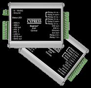
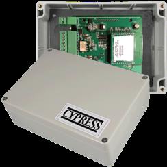
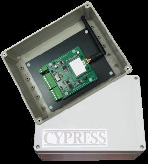
2 This manual covers the operation and setup of the Cypress Suprex RF SPX-5000 series wireless units. Overview: The SPX-5000 series of RF Wireless solutions provides a wireless bridge from Card Readers with gates or door hardware to most access control manufacturers panels. The SPX or Suprex products include both the remote ( Door/Gate ) unit and the central ( AC Panel ) unit. In the case of the SPX-5000 series of wireless products optional repeaters / extenders are also available. Features: -- Includes complete solution with remote ( reader/gate/door ) and central ( panel ) interface. -- Service mode for setup and configuration. -- Quiet protocol to conserve bandwidth and power -- Field configurable reader formats -- Multifunction indicator for determining operational status of the unit -- Auxiliary I/O connections available for Door/Gate/Panel status signaling. -- Multiplexing of RF bridge providing for additional door/gate on a single RF link. -- Economical expansion capabilities using Suprex Lynk technology RF Specifications: 2.4GHz or 900Mhz frequency AES Encryption upon request Cypress Suprex SPX-5000 Series Overview Electrical and Mechanical Specifications Physical Temp Humidity Weatherproof Enclosure - ABS - IP65 SPX units 6.75 x 4.75 x 2.10 (Each unit) - IOX units 7.25 x 5.75 x 3 Storage(-55 C to C) - Operating(-40 C to +80 C) 95% (non-condensing) Input Unreg Input 8 to mA Max Unreg Input 8 to mA Max ( IOX-7000 ) Output ( except IOX-7000 ) Data I/O Relays Interface Max Switching Running Spec with load Reader -Wiegand, Strobed (Clock & Data), F/2F LED V (220Vdc 30W (resistive) 1A) (250Vac 37.5VA 1A) (30Vdc 1A (resistive), 1 x 10 5 operations at 20 o C 125Vac.3A (resistive), 1 x 10 5 operations at 20 o C Cypress Computer Systems, Inc. Lapeer, MI Cypress Computer Systems Inc.
3 Suprex RF Part Numbers Part Number! Description!!!! Interface! UPC SPX Mhz - extender ft range Wiegand or Clock & Data RPT Mhz - repeater 1000 ft range N/A SPX GHz - extender 2000 ft range Wiegand or Clock & Data SPX GHz - extender ft range Wiegand or Clock & Data SPX GHz - extender 2000 ft range RS-232/RS RPT GHz - repeater 1000 ft range N/A IOX GHz - extender 2000 ft range N/A - Relays only Ambient Temperature (Degrees Celsius) Supply Voltage Temperature/Voltage de-rating curve The Suprex units should be operated with a filtered 12 Volt nominal DC supply. Any voltage between 8 and 16 volts can be utilized by following the temperature /voltage derating curve. Voltage should not exceed 16 VDC under normal operating conditions.
4 External connections and DIP Switch Settings 1-8 to 16 VDC In 2 - Status LED 1 - exp (+) 2 - exp (-) VDC out 4 - Prog Res Prog Res LED In 7 - D1/Data out 8 - D0/Clk out SPX-5000 Central 1- Relay 4 N.O. 2- Relay 4 Com 3 - Relay 4 N.C. 4 - Relay 3 N.O. 5 - Relay 3 Com 6 - Relay 3 N.C Aux out 9 - R2 in 10 - R1 in 1-8 to 16 VDC In 2 - Status LED 1 - exp (+) 2 - exp (-) VDC out 4 - R4 5 - R3 6 - LED out 7 - D1/Data In 8 - D0/Clk In SPX-5000 Remote 1- Relay 2 N.O. 2- Relay 2 Com 3 - Relay 2 N.C. 4 - Relay 1 N.O. 5 - Relay 1 Com 6 - Relay 1 N.C Aux in 9 - Not used 10 - Not used Central Unit Settings Remote Unit Settings DIP Switch #1 ON -Service Mode DIP Switch #1 OFF -Run Mode DIP Switch #1 ON -Service Mode DIP Switch #1 OFF -Run Mode Dip switch #4 is ON -Disable Pullup resistors Dip switch #4 is ON -Enable Pullup resistors Dip switch #4 is OFF -Enable Pullup resistors Wiegand Wiegand / No Filter Strobed Rising Edge (MR-5) Strobed Rising Edge (Dorad0 644) Strobed Rising (Mag-Tek) Strobed Falling Edge Reserved F2F Switch x 2 x 3 x x 4 x 5 x x 6 x x 7 x x x x = ON Dip switch #4 is OFF -Disable Pullup resistors Wiegand Wiegand / No Filter Strobed Rising Edge (MR-5) Strobed Rising Edge (Dorad0 644) Strobed Rising (Mag-Tek) Strobed Falling Edge Reserved F2F Switch x 2 x 3 x x 4 x 5 x x 6 x x 7 x x x x = ON
5 Quick Reference For Typical Connections SPX-5000 Series Central DC Supply +8 to +16 VDC Diagnostic LED Access Control Panel LED In D1/Data Out D0/Clock Out R1 IN R1 Input Controls Strike on Remote See page 10 for other strike control options SPX-5000 Series Remote DC Supply +8 to +16 VDC Diagnostic LED R1 N.O. R1 Com R1 N.C. Card Reader LED Out D1/Data In D0/Clock In Door Strike Output
6 Typical RF installation with repeater SPX-5000R (1) ACS SPX-5000C (1) RPT-5X51 ACS Typical RF installation - line of sight SPX-5000R (1) SPX-5000C (1) Typical RF installation - expansion modules EXP-2000R (2) EXP-2000R (3) SPX-5000C (1) ACS EXP-2000C (2) EXP-2000C (3) SPX-5000R (1) Wiegand connection Card reader RS-485 multi-drop Control and I/O
7 Quick Reference For Typical Connections Using Serial Interface Units DC Supply 1-8 to 16 VDC In 2 - Access Control Panel - RS RS-485 TXD RXD VDC out 2 - IN Not Used 4 - N.C. 5 - COM 6 - N.O Not Used 2- Not Used 3 - (-) RS (+) RS RS-232 TX 6 - RS-232 TX SPX-6000 Series Central Computer / PLC DC Supply 1-8 to 16 VDC In 2 - Serial RS-232 RFID Reader - RS RS-485 RXD TXD VDC out 2 - IN Not Used 4 - N.C. 5 - COM 6 - N.O Not Used 2- Not Used 3 - (-) RS (+) RS RS-232 TX 6 - RS-232 TX SPX-6000 Series Remote
8 Quick Reference For Typical Connections Using Serial Interface Units 1-8 to 24 VDC In 2 - DC Supply 1 - N.C. 2 - COM 3 - N.O. 4 - N.C. 5 - COM 6 - N.O Not Used 2- Not Used IN IN IOX-7000 Series Central DC Supply 1-8 to 24 VDC In N.C. 2 - COM 3 - N.O. 4 - N.C. 5 - COM 6 - N.O Not Used 2- Not Used IN IN IOX-7000 Series Remote
9 Door N.C. Contact 1K DC Supply Card Reader 1-8 to 16 VDC In 2 - Status LED 1 - exp (+) 2 - exp (-) VDC out 4 - R4 5 - R3 6 - LED out 7 - D1/Data In 8 - D0/Clk In SPX-5000 Remote 1- Relay 2 N.O. 2- Relay 2 Com 3 - Relay 2 N.C. 4 - Relay 1 N.O. 5 - Relay 1 Com 6 - Relay 1 N.C Aux in 9 - Not used 10 - Not used Gate/ Door Strike Request to Exit 1K DC Supply 1-8 to 24 VDC In 2 - Access Control Panel - RS RS-485 TXD RXD VDC out 2 - IN Not Used 4 - N.C. 5 - COM 6 - N.O Not Used 2- Not Used 3 - (-) RS (+) RS RS-232 TX 6 - RS-232 TX SPX-6000 Series Central Computer / PLC
10 Cypress Suprex RF Series - Setup and Pre-installation Unpacking: Remove covers from units and check interior for any shipping damage. Remove any packing material if present. Inventory any included parts (depending on model) such as antennas, coax cables etc. Bench Testing: Before installing the units in the field they should be assembled and tested at a convenient Bench top location. This will make it easier to verify / change settings and check operation when both units are visible at the same time. It is also a chance to become familiar with the system if this is the first time using the Suprex system. It is much more difficult to setup and test the units when they are several thousand feet apart. Both units will need to have the antenna and a suitable power supply connected. For testing purposes, the units can share the same power supply. During initial setup it is helpful to use the Setup/Config mode. This allows a relative indication of the radio link quality between the units. Basic Bench Test: 1. Connect any antennas if the unit was shipped without antennas installed. 2. Connect a suitable power supply to both units. Each unit should be provided with 8-16 volts DC and approx 300mA. Both units should be separated by a minimum of 24 inches. 3. Apply power. After about a 1-2 second delay both units Diagnostic LED should indicate Green. 4. Touch a jumper wire from the connection the the Relay 1 input on the Central unit. Relay #1 on the Remote unit should activate with an audible click and the Diagnostic LEDs should flash green on both the Central and Remote units. 5. Units are shipped from the factory set for the Wiegand data format. If a different format is required set the DIP switch to the required reader and panel format. 6. If a reader and panel is accessible, connect the reader to the Remote unit and the Central unit to the panel and verify that card reads are being accepted by the access control system. If any troubleshooting is necessary, it will be easier to do with both units in close proximity to each other. 7. Once these steps are completed, the units are ready for installation it their permanent locations and final commissioning as a system. Antenna orientation and field placement: See examples below for RF units with dipole antennae and chip antennae. The orientation of the dipole antennae is critical for performance. The antennae should always be oriented vertically. Orientation of RF units with integral chip antennae is not as critical. Radio frequencies in the 900 MHz and 2.4 GHz bands have characteristics that require LOS Line of sight between the transmitter and receiver. For best performance the antennas of the Central and Remote should see each other without obstructions. There are limited exceptions where the signal will still pass between the transmitter and receiver without line of sight placement. In some cases, the communication path will work but at a reduced distance. When possible, for outdoor installations place the units on the exterior of buildings to reduce interference. Repeaters/ Boosters are available if needed. Dipole antenna example Chip antenna example
11 Cypress Suprex RF Series - Indicators and Operating Modes LED Diagnostic Indicator: The LED Diagnostic indicator provides information on the operational status of the unit. If the units are not communicating, viewing the diagnostic indicator LED s may help to determine the nature of the problem. When the Suprex units are operating correctly and have a valid communication channel between the Remote and Central units, the Diagnostic indicators on each unit will flash green rapidly (2-3 flashed per second) in Service / Config mode and illuminate a steady green in quiet mode. DIAGNOSTIC LED NOT ILLUMINATED: If the LED(s) are not illuminated on the unit(s) then the unit is not getting power or there is an electrical problem. The Diagnostic LED s will be illuminated Red/Green or flashing whenever power is applied. CENTRAL UNIT FLASHING BETWEEN RED/GREEN: With power applied and no communication path between the Remote and Central, the Central unit will flash the diagnostic indicator alternately between Red and Green. REMOTE UNIT ILLUMINATED RED: The Remote unit will diagnostic LED will illuminate solid (not flashing) red if it is not receiving communication from the Central. REMOTE AND CENTRAL UNITS FLASHING BETWEEN RED/GREEN: The Central is not Receiving communication from the Remote. Operating modes: By setting DIP switch 1 to the ON position, the unit is placed in Setup / Config mode. When the switch position is changed, cycle power to the unit to make the switch change take effect. In "Quiet" mode (DIP switch #1 OFF) the units will remain quiet unless there is a status change, and will slowly poll each other about every 10 to 15 seconds to check the link integrity. The Setup / Config mode places the units in a rapid polling sequence to allow troubleshooting and setup of the communication link. The Suprex RF units use a quiet protocol when operating in Quiet mode. Communication between the Central and Remote unit only occurs when an event requires data transmission or contact needs to be made to maintain supervision. The RF channel remains quiet most of the time. During setup or troubleshooting it may be necessary to observe the communication link between the Central and Remote units. The rapid polling used in the Setup / Config mode can help indicate whether the units can See each other. Additionally the Central unit Diagnostic LED will indicate Red when communication is lost. In some cases an optimal mounting location can be selected by operating one of the units on a small 12 volt battery and moving the location while observing the diagnostic LED indicators.
12 Cypress Suprex RF Series - Door Strike and LED I/O To activate the relay on the Remote unit, connect as shown below. These connections can be used to allow the Remote relay to operate a DOOR STRIKE, GATE, or other locking hardware. Refer to following pages in this document for details of each I/O operation and connection. There are two relays available for accessory outputs at the Remote end. Either relay can be used to provide the Door Strike or Gate activation function. This example uses Relay 1. Wiring Example - Door Strike Follows LED Suprex RF Central Access Control Panel LED Signal LED In R1 Input Controls Strike on Remote R1 IN Only Relay and LED Connections are shown for clarity, refer to previous diagrams for and Data connections. Wiring Example - Door Strike does not follow LED Suprex RF Central Access Control Panel N.O. Com LED Signal Strike Signal LED In R1 Input Controls Strike on Remote R1 IN
13 Cypress Suprex RF Series - Door Strike and LED I/O The Cypress SPX-5000 provides additional data channels to support access control hardware such as door strikes, tamper alarms, request to exit status, etc. These signals are sent to and from the Remote and Central units without the need to run additional wiring. The accessory control I/O use active low inputs. When the inputs are floating (nothing connected) the associated output will be set to a high level. When the input is set to 0Volts () the input will activate its associated output. All Accessory outputs are Open Collector type and will switch to when activated. Each input will have an associated output. See the following pages for a diagram of each I/O pair.inputs can be tested by making a jumper connection to ground and monitoring the associated output. Suprex RF Central Jumper to ground to test Input LED In Red arrow denotes direction of command signal Suprex RF Remote Output LED Out
14 Cypress Suprex RF Series - Relay Controls Suprex Central Relay 3 N.O. Relay 3 Com Relay 3 N.C. Relay 4 N.O Relay 4 Com Relay 4 N.C. Suprex Central Contact Outputs Contact Outputs Red arrow denotes direction of command signal Suprex Remote Suprex Remote Input Signal (5Volts DC Maximum) Relay 3 IN Input Signal (5Volts DC Maximum) Relay 4 IN Relay 3 functions as an Alarm relay and monitors the condition of the communication link between the Central and Remote units. Relay 3 is activated when power is applied and the communication link between the Central and Remote is functioning. Relay 3 will become deactivated (Alarm condition) when either the Relay 3 input on the remote is active OR the Remote unit is unable to communicate with the Central unit. See APP NOTE FOR DETAILS
15 SPX-XXXX Application Note Using Supervised Contacts with the SPX-series Extenders Applies to the following products: SPX-5501, SPX-5601, SPX-5521, SPX-5621, SPX-7400, SPX-7410, SPX-7200, SPX-7500, All RIM series products. This application note describes the connections necessary to convey supervised contact status over a Suprex communication link. The configurations described in this app note should apply to most panels that utilize supervised contacts. When connected as described, the Suprex system will provide a supervised signal to the panel interface by reading the supervised status of the contacts connected to the Suprex Remote unit. Theory of operation: The Access control panel is looking for a certain value of resistance connected to the supervised contact terminals. The Suprex Central unit will provide these resistance values locally at the panel so that the correct supervised status is maintained. At the same time, the Remote unit must maintain supervision of the wires connected to the relays and switches that are connected to the remote access point. The contact supervision is provided by the Remote unit. The Suprex system does this by comparing the value of programming resistor at the Central unit with the resistance seen at the Remote interface terminals. When there is a difference in the two values, the Relay on the Central unit is activated. There are two different examples. One example is monitoring a normally closed contact at the Remote unit, and the other example is monitoring a normally open contact at the Remote unit. In the examples given, a normally closed contact will require a programming resistor of 1K and a normally open contact will require a programming resistor of 2K. Other resistor values can be used but 1K resistors are the most common. Other resistance values will require different value(s) for the programming resistor(s). 2K 1K 8 to 16 VDC In Diagnostic LED exp (+) exp (-) +5 VDC out Prog Res 4 Prog Res 3 LED In D1/Data out D0/Clk out Central Unit Relay 4 N.O. Relay 4 Com Relay 4 N.C. Relay 3 N.O. Relay 3 Com Relay 3 N.C. Aux out R2 in R1 in 1K 1K I1- I1+ I2- I2+ Door N.C. Contact Rex N.O. Contact 1K 1K 1K 1K 8 to 16 VDC In Diagnostic LED exp (+) exp (-) +5 VDC out R4 R3 LED out D1/Data In D0/Clk In Remote Unit Relay 2 N.O. Relay 2 Com Relay 2 N.C. Relay 1 N.O. Relay 1 Com Relay 1 N.C. Aux in Not used Not used
16 SPX-5000 Setup - Using Expansion Modules Before using EXP-2000 Expansion modules with the SPX-5000 system, it will be necessary to perform a short configuration process. This process determines if the 5000 will utilize expansion modules, and if so, how many will be used with the system. Each SPX-5000 link can support up to 2 expansion modules. SPX-5000 units are shipped in the factory default condition. Factory default units will be setup to function as SPX-5000 units without expansion modules. Only communications between the 2 gateway units will be active. Setup Process: 1. With power off, set the DIP switch on the Central unit according to the table below. 2. Apply power. The Diagnostic LED should display a steady Green indication. 3. Remove power Set DIP switch #1 OFF. Any other DIP switches can now be set as required (Reader family/ Pullup resistors). The Central unit is now configured. No expansion module configuration is required for the Remote unit. 4. The expansion modules will need to be setup and correctly addressed. See EXP-2000 manual for details of Expansion module setup and configuration. The Expansion units are addressed, and added to the system as pairs. 5. Connect the Expansion modules into the system as indicated in this wiring diagram. Operation with Expansion Modules: The SPX-5000 system Remote and Central gateway units will operate as a standard pair Suprex units, all of the I/O and data terminals are available for use with readers and access control systems. There are some minor differences in operation when using the expansion modules. Each pair of 1. The Diagnostic LED on the Gateway units will indicate the status of the main (gateway) communication link only. 2. The Alarm relay on the Central Gateway unit will deactivate (indicate alarm condition) when the communication fails between the Gateway units or ANY of the the Remote or Central Expansion units. 3. Paired Expansion units will be functionally similar to the standard Cypress SPX-1300 Suprex system. Central Unit Configuration Mode Settings!!! Switch!!! Gateway only - No EXP! EXP Pair used!! EXP Pair used!! = ON 0 = OFF See EXP-2000 Manual for further setup instructions
17 Cypress Suprex Wireless Solution with Wiegand expansion modules Door / Parking Gate - Typical SPX-5000R (1) EXP-2000R (2) EXP-2000C (3) EXP-2000R (3) ACS EXP-2000C (2) SPX-5000C (1) Card Reader Wiegand Data RS-485 Link - Multi-drop Control and I/O
18 Cypress Suprex Series - Wiegand Expansion Module Panel Central interface DC Supply +8 to +16 VDC EXP(+) EXP(-) SPX-XXXX Central Access Control Panel LED In D1/Data Out D0/Clock Out R1 IN R1 Input Controls Strike on Remote 8 to 16 VDC In 485(+) 485(-) +5 VDC Out Prog Res 4 Prog Res 3 * LED Input D1/Data Out D0/Clock Out EXP-2000 Central Unit RLY4 N.O. RLY4 Com RLY4 N.C. RLY3 N.O. RLY3 Com RLY3 N.C. RS232 Out RS232 In Aux Out Relay2 Input Relay1 Input Additional EXP Modules See EXP-2000 Manual for further setup instructions
19 Cypress Suprex Series - Wiegand Expansion Module Reader/Door Remote interface DC Supply 8 to 16 VDC In SPX-XXXX Remote EXP (+) EXP (-) R1 N.O. R1 Com R1 N.C. Door Strike Output Card Reader LED Out D1/Data In D0/Clock In 8 to 16 VDC In 485(+) 485(-) +5 VDC Out RLY4 Input (5V) RLY3 * Input (5V) LED Output D1/Data Input D0/Clock Input EXP-2000 Remote Unit RLY2 N.O. RLY2 Com RLY2 N.C. RLY1 N.O. RLY1 Com RLY1 N.C. RS232 Out RS232 In Aux In N/C N/C Additional EXP Modules See EXP-2000 Manual for further setup instructions
20
Suprex RF Series CYPRESS. Operations Manual. Suprex Reader Extender - RF Wireless Interface EXP SPX Mhz SPX-5521_MAN_0316
 CYPRESS Suprex RF Series Operations Manual Suprex Reader Extender - RF Wireless Interface EXP-2000 SPX-5521 900 Mhz SPX-5521_MAN_0316 Cypress Suprex SPX-5521 Series Overview This manual covers the operation
SPX-7400 Series. Operations Manual. Suprex Reader Extender - Fiber Optic Interface. SPX-7400 shown with EXP-2000 SPX-7400_MAN_082112
 SPX-7400 Series Operations Manual Suprex Reader Extender - Fiber Optic Interface SPX-7400 shown with EXP-2000 SPX-7400_MAN_082112 This manual covers the operation and setup of the Cypress Suprex Fiber
SPX-7200 Series SPX-7200 EXP Operations Manual. Suprex Reader Extender - Ethernet SPX-7200_MAN_082112
 SPX-7200 Series Operations Manual Suprex Reader Extender - Ethernet SPX-7200 EXP-2000 SPX-7200_MAN_082112 Cypress Suprex SPX-7200 Series Overview This manual covers the operation and setup of the Cypress
SPX-7400_SPX-7410_MAN_161028
 Suprex Fiber Optic SPX-7400 & SPX-7410 Suprex Reader-Extender Data Sheet SPX-7400 Series EXP-2000 SPX-7400_SPX-7410_MAN_161028 1 Cypress Suprex SPX-7400 & SPX-7410 Overview The Suprex Fiber Optic SPX-7400
Suprex Fiber Optic. Reader-Extender SPX-7400 SPX Product Manual. Reader-Extender. Manual. SPX-7400 Series EXP Suprex_FiberOptic_MAN_170502
 Suprex Fiber Optic Reader-Extender SPX-7400 SPX-7410 Product Manual Reader-Extender Manual SPX-7400 Series EXP-2000 Suprex_FiberOptic_MAN_170502 Cypress Integration Solutions 30+ Years of Access Control
Suprex RS-485 SPX-7500 Wired Reader-Extender
 Suprex RS-485 SPX-7500 Wired Reader-Extender Product Manual SPX-7500_MAN_181206 Cypress Integration Solutions 35 Years of Access Control Ingenuity CypressIntegration.com 2018 Cypress Computer Systems 1778
CYPRESS " " EXP SPX Expansion interface! modules EXP-2000_MAN_0314
 CYPRESS EXP-2000 SPX Expansion interface! modules The EXP-2000 provides additional Door/Panel interface points to most SPX products. The EXP-2000 uses a local RS-485 network through an SPX gateway device.
Suprex Ethernet SPX-7200 Ethernet Reader-Extender
 Suprex Ethernet SPX-7200 Ethernet Reader-Extender Product Manual 1 SPX-7200_MAN_181206 Cypress Integration Solutions 35 Years of Access Control Ingenuity CypressIntegration.com 2018 Cypress Computer Systems
FDW1000(M,S) OPTICAL WIEGAND, MAGSTRIPE & F/2F DATA EXTENDER INSTALLATION AND OPERATION MANUAL
 OPTICAL WIEGAND, MAGSTRIPE & F/2F DATA EXTENDER INSTALLATION AND OPERATION MANUAL") OPTICAL WIEGAND, MAGSTRIPE & F/2F DATA EXTENDER This manual serves the following ComNet Model Numbers: FDW00M/C FDW00S/C FDW00M/R FDW00S/R EXP0C EXP0R The ComNet FDW00 data extenders provide optical connectivity
OPTICAL WIEGAND, MAGSTRIPE & F/2F DATA EXTENDER This manual serves the following ComNet Model Numbers: FDW00M/C FDW00S/C FDW00M/R FDW00S/R EXP0C EXP0R The ComNet FDW00 data extenders provide optical connectivity
CVX-1300 DataBender! Universal Format Converter!
 CVX-1300 DataBender! Universal Format Converter! User Manual CVX-1300_MAN_0114 Electrical and Mechanical Specifications Physical Temp Aluminum enclosure Size 3.5 x 2.75 x.75 Storage (-55 C to +150 C) Operating
RS232 TO WEIGAND INTERFACE
 RS232 TO WEIGAND INTERFACE The RS232 provides data format and protocol translations of numerous card reader technology outputs into almost any other standard or proprietary format. More than 100 format
CVX-1300 CVX DataBender. Universal Format Converter. User Manual
 CVX-1300 CVX-1300 DataBender Multi-Format Converter DataBender Product Manual Universal Format Converter User Manual CVX-1300_MAN_181217 Cypress Integration Solutions 35 Years of Ingenuity CypressIntegration.com
SIO-7300 CYPRESS. Wiegand / Ethernet converter with General I/O control. SIO-7300!Part 15 Class A SIO-7300_MAN_190108
 CYPRESS Wiegand / Ethernet converter with General I/O control Part 15 Class A _MAN_190108 Electrical and Mechanical Specifications Physical Temp Humidity - Aluminum Enclosure 4.45 x 3.08 x 2.0 ( Each Unit
SPX Supervised Reader Extender. Wiring Diagram and Operators Manual MAN-FA-SPX-1200 V1.03
 SPX-1200 Supervised eader Extender Wiring Diagram and Operators Manual MAN-FA-SPX-1200 V1.03 2005 ypress omputer Systems,Inc. www.cypressworld.com Page 1 Table of ontents Quick eference guides Page 3,4
OSM Features: Field Configurable Reader,I/O to OSDP OSDP to Panel
 OSM-1000 Universal OSDP Interface Module Series Features: Field Configurable Reader,I/O to OSDP OSDP to Panel Interfaces and Formats Wiegand ( 4 to 300 bits) F/2F (Binary, ABA) Strobed ( Wiegand, ABA )
HHR-3150 Series System Handheld Wireless Reader Kit with dual Wiegand output
 HHR-3150 Series System Handheld Wireless Reader Kit with dual Wiegand output Product Manual Applications: Rapid disaster deployment Handheld relay control for security officer empowerment (use for functions
Quick Start Installation Guide
 apc/l Quick Start Installation Guide Version A2 Document Part Number UM-201 May 2010 OVERVIEW The apc/l is an intelligent access control and alarm monitoring control panel which serves as a basic building
HHR-3260 SYSTEM Handheld Wireless Reader Kit with 2 readers and dual Wiegand output
 HHR-3260 SYSTEM Handheld Wireless Reader Kit with 2 readers and dual Wiegand output Applications: Rapid disaster deployment Handheld relay control for security officer empowerment (use for functions such
WRI400 WIRELESS READER INTERFACE
 WRI400 WIRELESS READER INTERFACE Technical Services Training for the WRI400 Launched April 2011 March 12 Technical Services Engineering Support 1 Training Overview WRI400 Description Information Installation
INSTALLATION INSTRUCTIONS 921P EntryCheck TM
 80 Avenida Acaso, Camarillo, Ca. 90 (805) 494-06 www.sdcsecurity.com E-mail: service@sdcsecurity.com INSTALLATION INSTRUCTIONS 9P EntryCheck TM The EntryCheck 9P Indoor/Outdoor Keypad is a surface mount
January 2013 PRICE SCHEDULE A 2.0. Access Plus Telephone Entry & Access Control
 January 2013 PRICE SCHEDULE A 2.0 Section A4 Date Page Comment 1 1 13 All January, 2013 Price Schedule update. 2 13 13 6 Removed 1812 092 from 1812 145 kit. Added 1812 092 to 1812 147 kit. 2 13 13 9 P/N
April 2015 PRICE SCHEDULE A 2.0 Stand-Alone Access Control
 Section A6 This Price Schedule is effective April 1, 2015. Date Page Comment 4-1-15 All April, 2015 Price Schedule update. 5-8-15 3 Removed model 1503. Added models 1509 / 1515 (Pg 15) to the TOC. 8-10-15
THE BRIDGE. Make any Wiegand device wireless with the Sure-fi Bridge FEATURES. Technology
 THE BRIDGE Make any Wiegand device wireless with the Surefi Bridge *Housing options sold separately. Keep your Wiegand system connected. Fix faulty Wiegand systems quickly and easily with our wireless
6222 Two Door Module Technical Operations Manual
 6222 Two Door Module Technical Operations Manual TABLE OF CONTENTS Specifications...3 Overview...4 Operations...5 Custom Access Mode...5 Standard Access Mode...5 Offline Access Mode...5 Offline Memory...5
UC-2000 Installation Manual Unicorn Computers Technology Limited
 UC2000 Installation Manual Copyright 2003. All rights reserved. Table of Contents Specifications 2 Enclosure for the UC2000 Controller 3 Unicorn Access Control System Configuration 4 UC2000 Controller
Amano (itrt) Intelligent Twin Reader Terminal INSTALLATION MANUAL
 Intelligent Twin Reader Terminal INSTALLATION MANUAL") MODEL NUMBER: XRT910-0-0-AC-XX XRT920-0-0-AC-XX AMANO itrt Amano (itrt) Intelligent Twin Reader Terminal INSTALLATION MANUAL SPECIFICATIONS Working Environment Plastic Housing... Power Designed to work
MODEL NUMBER: XRT910-0-0-AC-XX XRT920-0-0-AC-XX AMANO itrt Amano (itrt) Intelligent Twin Reader Terminal INSTALLATION MANUAL SPECIFICATIONS Working Environment Plastic Housing... Power Designed to work
INSTALLATION INSTRUCTIONS 920P EntryCheck TM
 801 Avenida Acaso, Camarillo, Ca. 93012 (805) 494-0622 www.sdcsecurity.com E-mail: service@sdcsecurity.com INSTALLATION INSTRUCTIONS 920P EntryCheck TM The EntryCheck 920P Indoor/Outdoor Keypad is a surface-mount
MR52 READER INTERFACE
 IN IN2 IN3 IN4 INPUTS IN5 IN6 IN7 IN8 C www.mercury-security.com 2355 MIRA MAR AVE. LONG BEACH, CA 9085-755, (562)986-905 FAX (562) 986-9205 MR52 READER INTERFACE Installation and Specifications: This
PRT-RDS2 Standard 2 Reader Expander
 PRT-RDS2 Standard 2 Reader Expander Installation Manual CONTENTS Protégé System... Introduction... Reader Expander... Features... Reader Expander Specifications... Protégé System Management Suite... Protégé
EA500. Installation Instructions Transponder
 EA500 EN Installation Instructions Transponder EA500 Installation Instructions 1.0 Overview EN 2 1.0 Overview The EA500 Transponder is the Security Escort module that provides communications between the
AC-115 Compact Networked Single-Door Controller Hardware Installation and Programming
 AC-115 Compact Networked Single- Controller Hardware Installation and Programming Copyright 2013 by Rosslare. All rights reserved. This manual and the information contained herein are proprietary to REL,
PCR43304R, PCR43304RE 4-Channel, 433MHz Penta Receiver with Frequency Hopping
 PCR43304R, PCR43304RE 4-Channel, 433MHz Penta Receiver with Frequency Hopping Features Frequency hopping between 433.10 to 434.70MHz 12-way dipswitch or encrypted coding Momentary and latching modes are
MR51e Reader Interface
 J4 J TB6 TB5 TB4 TB3 VIN VO TB2 TB J7 2.75 [69.85] 0.2 [5.08] 2.35 [59.69] J3 MR5e Reader Interface Installation and Specifications. General: www.mercury-security.com 2355 MIRA MAR AVE. LONG BEACH, CA
INSOMNIAC CIA G-600 Gateway Installation Manual P/N CIA Revision 1.0 Date Code:
 INSOMNIAC CIA G-600 Gateway Installation Manual P/N CIA-675-001 Revision 1.0 Date Code: 1-1-2018 Table of Contents Table of Figures... 3 SPECIFICATIONS:... 4 INSTALLATION... 5 General:... 5 Physical Installation
PCR43304R, PCR43304RE 4-Channel, 433MHz Penta Receiver with Frequency Hopping
 PCR43304R, PCR43304RE 4-Channel, 433MHz Penta Receiver with Frequency Hopping Features Frequency hopping between 433.10 to 434.70MHz 12-way dipswitch or encrypted coding Momentary and latching modes are
e-ask electronic Access Security Keyless-entry
 e-ask electronic Access Security Keyless-entry CAN Multiplex System CAN Multiplex System Installation & Instructions (UM27 ~ 24324-03) Table of Contents Introduction... 1 e-pad Operation and Features...
NetGen Hardware Installation Guide. for NetGen Ethernet Door Controllers
 NetGen Hardware Installation Guide for NetGen Ethernet Door Controllers 0613 Table of Contents BLUEWAVE SYSTEM OVERVIEW...2 THE WI-FI LOCK AND SECURITY COMPANY...2 NETGEN DOOR CONTROLLERS...2 INSTALLATION
CA-A480-A Elevator Controller. Reference & Installation Manual
 CA-A480-A Elevator Controller Reference & Installation Manual TABLE OF CONTENTS INTRODUCTION.................................................................. 4 Introduction.............................................................................................
GL-104 ENCODER/DECODER MANUAL GLOLAB CORPORATION
 GL-04 ENCODER/DECODER MANUAL GLOLAB CORPORATION Thank you for buying our Encoder / Decoder Module. The goal of Glolab is to produce top quality electronic kits, products and components. All of our kits
User Manual. PCKeypad Wireless Keypad
 User Manual PCKeypad Wireless Keypad Description The PCKeypad is a wireless keypad with a PentaCODE transmitter built-in. It works with all of Elsema s PCR series receivers. The installer has the option
VertX. V100, V200 and V300. Installation Guide Barranca Parkway Irvine, CA USA. November Rev A.1
 15370 Barranca Parkway Irvine, CA 92618 USA VertX V100, V200 and V300 Installation Guide November 2011 6080-930 Rev A.1. Contents Introduction... 3 Parts List... 3 Product Specifications... 3 Cable Specifications...
9212i INSTALLATION. Stand-Alone Keypad. Instructions
 INSTALLATION 9212i Stand-Alone Keypad Instructions Features: 4 Independent Outputs 4 Independent Timers All Outputs Assignable by Code On board 5 Amp Form C Relay 120 Users Remote Triggering Input Keypad
Proximity Card and Pin Reader Installation Manual
 Multi Prox Proximity Card and Pin Reader Installation Manual PUBLICATION INFORMATION 60A9 - Draft Release Version 0.1.2 71D0 - Version 1.0.5 CONTENTS Introduction... 1 Legend... 2 Terminology... 2 Mounting...
WIRELESS GATEWAY DUOS
 WIRELESS GATEWAY DUOS REF.: PA160410210 / PA160411910 Wireless Gateway DUOS is an easy-to-use solution specially designed to create a network of physical data monitoring, such as: temperature and relative
MCX402DR-BRD I/O expander. Operating Manual
 Roger Access Control System MCX402DR-BRD I/O expander Operating Manual Product version: 1.0 Firmware version: 1.0.2.255 Document version: Rev. B Design and application The MCX402DR-BRD is I/O expander
RD-SR2 ACCESS SECURITY PRODUCTS LTD. Proximity Card Reader with Remote Control. User Manual
 RD-SR2 Proximity Card Reader with Remote Control User Manual INTRODUCTION The RD-SR2 is a compact, weather resistant multi-function card reader that can be used as a standalone programmable access control
D/E Remote Relay Panel User Guide
 D/E Remote Relay Panel User Guide This manual should remain with the unit. D/E Remote Relay Panel Detailed Specifications...2 Environmental Specs...2 Power Supply Requirements...2 Relay Outputs (8)...2
Secured Series: Hub Plus Kit Single Door Controller Package Installation Manual
 Secured Series: Hub Plus Kit Single Door Controller Package Installation Manual This package is designed to simplify the connections to our Secured Series Hub Plus Controller. This will translate into
INSTALLATION INSTRUCTIONS 920 EntryCheck TM
 801 Avenida Acaso, Camarillo, Ca. 93012 (805) 494-0622 www.sdcsecurity.com E-mail: service@sdcsecurity.com INSTALLATION INSTRUCTIONS 920 EntryCheck TM The EntryCheck 920 Indoor/Outdoor Keypad is a surface-mount
DNETEXT-C CAN Bus Extender, Version 3 User s Manual. Brad Harrison
 DNETEXT-C CAN Bus Extender, Version 3 User s Manual Brad Harrison Although every effort has been made to insure the accuracy of this document, all information is subject to change without notice. Woodhead
CRC220 and CRC221 INSTALLATION GUIDE. REF No.: DOC0014 ISSUE: 09
 CRC220 and CRC221 INSTALLATION GUIDE REF No.: DOC0014 ISSUE: 09 30th July 2015 2 Contents CRC220 & CRC221 INSTALLATION GUIDE 1. Scope 1-1 2. Introduction 2-1 2.1 Features 2-1 2.1.1. PCB Features 2-1 2.1.2.
VISTA 12a / 48a TECHNICAL TRAINING. The Best in Security plus Everyday Convenience & Control
 VISTA 12a / 48a TECHNICAL TRAINING The Best in Security plus Everyday Convenience & Control Version #.007 7th June 2005 VISTA 12a / 48a Training Guide Index 1. Vista Family Features....... p. 3 2. Wiring
F6-Fingerprint. Access Control/Reader. User Manual. F6 - Simplified Instruction. (Master Code) # (Factory default:1234) Enter the Programming Mode
 # (Factory default:1234) Enter the Programming Mode") -Fingerprint Access Control/Reader Function Description Enter the Programming Mode - Simplified Instruction Operation (Factory default:1234) Change the Master Code Add Fingerprint User Add Card User Add
-Fingerprint Access Control/Reader Function Description Enter the Programming Mode - Simplified Instruction Operation (Factory default:1234) Change the Master Code Add Fingerprint User Add Card User Add
PIB300 and PIB301 User Guide. Installation and operation instructions for Panel Interface Board
 *P516-097* P516-097 PIB300 and PIB301 User Guide Installation and operation instructions for Panel Interface Board Para el idioma español, navegue hacia www.schlage.com/support Pour la portion française,
PCR43301RE 1-Channel, 433MHz Penta Receiver with Frequency Hopping
 PCR43301RE 1-Channel, 433MHz Penta Receiver with Frequency Hopping Features Frequency hopping between 433.10 to 434.70MHz 12-way dipswitch or encrypted coding Compatible with PentaFOB and PentaCODE remotes
Quantum III. Compact DC Drive Package. Slitter DC Drive Package. Quantum III
 Compact DC Drive Package The delivers a DC drive package that integrates the intelligence of the Mentor II with a space saving design that incorporates many accessories typically required in the North
Dupline. Data Logger. Types G , G Product Description. Ordering Key G Type Selection. Input/Output Specifications
 Dupline Data Logger Types G 800 006, G 800 106 Product Description Programmable channel generator with optional built-in GSM Modem Event and time based data logging functions for digital, analog and counter
ACTsmart2 Product Range Operating and Installation Instructions
 ACTsmart2 Product Range Operating and Installation Instructions 18-00045 Contents ORDERING INFORMATION......4 INSTALLATION NOTES......5 IMPORTANT......5 PRODUCT SPECIFICATION......5 30 SECOND PROGRAMMING
WIRELESS EXPANSION SYSTEMS
 WIRELESS EXPANSION SYSTEMS Residential Apartment/College Residence Halls Gated Communities Mixed Use Buildings Commercial/Industrial Parking Self Storage Maximum Security Wireless Systems Access Control
PCR43301RE ELSEMA. . and anywhere else you need a wireless signal to transmit a contact closure. Description
 PCR43301RE 1-Channel, 433MHz Penta Receiver with Frequency Hopping Features Frequency hopping between 433.10 to 434.70MHz 12-way dipswitch or encrypted coding Compatible with PentaFOB and PentaCODE remotes
PXL-250 Tiger Controller
 PXL-0 Tiger Controller This quick start guide is made up of specification sheets, a DO/DON T list, basic installation drawings, first time power-on instructions, and short descriptions of key terms and
SINGLE READER EXPANSION MODULE
 SINGLE READER EXPANSION MODULE INSTALLATION GUIDE A D C - A C X 1 TR- SINGLE READER EXPANSION MODULE The ADC-ACX1 Single Reader Expansion Module provides a solution for interfacing to a one Wiegand reader
Two Door Controller GEN-045
 Australian Owned, Designed and Manufactured Two Door Controller GEN-045 Genesis Electronics Australia Pty Ltd www.genesiselectronics.com.au Distributed by: Genesis reserves the right to change or modify
PCR43302RE, PCR43302R 2-Channel, 433MHz Penta Receiver with Relay outputs
 PCR43302RE, PCR43302R 2-Channel, 433MHz Penta Receiver with Relay outputs Features Frequency hopping between 433.10 to 434.70MHz Coding using 12-way dipswitch or encrypted codes Momentary and latching
DOLXFD1000B. Waterproof Access Control/Reader
 DOLXFD1000B Waterproof Access Control/Reader INTRODUCTION The DOLXFD1000B is a single- entry multi-function Access Controller with integrated keypad and card reader. It is designed and manufactured to
Web-based Access Control System. Employee access. EMBEDDED Web Browser
 Web-based Access Control System NetAXS-123 Hybrid Access Control Panel Honeywell s web-based NetAXS controller provides solutions for installations of any size. NetAXS-123 enables users to securely manage
AW58300HTP-PAIR USER S MANUAL
 USER S MANUAL 5.8 GHz Outdoor 300 Mbps Ethernet Point-to-Point Radio System Industrial-grade, long-range wireless Ethernet systems AvaLAN W I R E L E S S The AW58300HTP-PAIR consists of two AW58300HTS
DG-800 Stand-Alone Proximity Reader Instruction Manual
 DG-800 Stand-Alone Proximity Reader Instruction Manual I. Features 1. Memory volume up to 1000+10 proximity cards/tokens and PINs with the programming time up to 0.5 seconds. 2. Access modes: a. Only Proximity
GL116 ENCODER/DECODER MANUAL GLOLAB CORPORATION
 GL ENCODER/DECODER MANUAL GLOLAB CORPORATION Thank you for buying our GL Encoder / Decoder Module. This device was developed in response to many requests for an encoder and decoder that would serialize
Stand-alone Proximity Access Control
 Stand-alone Proximity Access Control User Manual INTRODUCTION VIDI-AC-1C is a compact, waterproof stand-alone programmable access control system that provides proximity entry for up to 2000 users. It uses
NetAXS-123: One door, compact (plastic) enclosure. NetAXS-123: One door, standard (metal) enclosure with tamper switch and terminal block
 enclosure. NetAXS-123: One door, standard (metal) enclosure with tamper switch and terminal block") Honeywell s web-based access control offering now provides solutions for installations of any size. NetAXS enables users to manage their system anywhere there s an Internet connection with no dedicated
Honeywell s web-based access control offering now provides solutions for installations of any size. NetAXS enables users to manage their system anywhere there s an Internet connection with no dedicated
PA5000 SERIES USER MANUAL
 PA5000 SERIES 4G CELL PHONE ENTRY SYSTEM USER MANUAL Rev. C Platinum Access Systems Inc. PRODUCT LINE PA5020 --- Cell Phone Entry System PA5022 --- Cell Phone Entry System (Flush Mount) SPECIFICATIONS
2000 Series e/em Style Keypad Installation and Programming Manual
 2000 Series e/em Style Keypad Installation and Programming Manual Document Number: 6054022 Revision: 0 Date: 12/21/06 Table of Contents Table of Contents Section 1: Introduction... 6 1 Product Description...6
January 2013 PRICE SCHEDULE A 2.0 PC Programmable Telephone Entry & Access Control. PC Programmable Telephone Entry & Access Control
 January 2013 PRICE SCHEDULE A 2.0 Section A3 Date Page Comment 10-1-13 All October, 2013 Price Schedule update. 1-25-13 18 Added part numbers to TagMaster products. 2-13-13 9 Removed wireless wiegand devices
adaptiverf IMPL-10 Wireless IP Bridge User Guide expertise in wireless design June adaptiverf Ltd Preliminary DS-IPML-10-1V0 Page 1
 IMPL-10 Wireless IP Bridge User Guide June 2008 2008 adaptiverf Ltd Preliminary DS--1V0 Page 1 Contents Package Contents... 3 Introduction... 3 Topologies Supported... 4 1. Point to Point... 4 2. Point
Web-based Access Control System. Lower Cost of Ownership
 Web-based Access Control System NetAXS-123 Hybrid Access Control Panel Honeywell s web-based NetAXS controller provides solutions for installations of any size. NetAXS-123 enables users to securely manage
Each receiver has 4 switched outputs, which, using our one touch easy-learn process can be controlled from any switch on any compatible transmitter.
 SABRE Series RUGGED REMOTE CONTROL SYSTEM Features 4 switch relays - 1200W each Up to 4000m Range 12-32Vac/dc and 230Vac supply Completely waterproof ABS enclosure (IP68) All outputs momentary, latching
Process displays For current and voltage
 Features Voltage input TRMS-AC/DC up to 600 V Current input AC/DC 1 A, 5 A and shunt (precision resistor) 60 or 100 mv With 2 or 4 limits Display range can be linearised Min, Max, Hold functions 4 20 ma
S125 Multi-Purpose 125 KHz RFID Reader USER MANUAL. 9V/24V DC Operating Voltage, AC (optional) KHz RFID EM4100/2 Cards & Tags
 KHz RFID EM4100/2 Cards & Tags") S125 Multi-Purpose 125 KHz RFID Reader 44 mm USER MANUAL MULTI PURPOSE 84 mm ONLINE & OFFLINE MODE BUILT-IN RELAY 125 KHz RFID EM4100/2 Cards & Tags 9V/24V DC Operating Voltage, AC (optional) 3 Online
S125 Multi-Purpose 125 KHz RFID Reader 44 mm USER MANUAL MULTI PURPOSE 84 mm ONLINE & OFFLINE MODE BUILT-IN RELAY 125 KHz RFID EM4100/2 Cards & Tags 9V/24V DC Operating Voltage, AC (optional) 3 Online
RBR-SB-KTZ001 LAR 2. User Manual
 RBR-SB-KTZ001 LAR 2 User Manual INTRODUCTION KTZ001 is a compact, waterproof stand-alone programmable access control system that provides proximity entry for up to 2000 users. Read both EM and HID card.
7612 Programming Instructions
 7612 Programming Instructions Built-in Proximity reader Read Range 65mm odulation ASK at 125kHz Compatible Cards ALL 26-Bit EM Cards 7612 is a vandal resistant proximity card and keypad access control
EMSwitch RF Switch Plug-In Card
 EMSwitch RF Switch Plug-In Card User Manual Model 7001-001 Model 7001-003 Model 7001-002 (not all models shown; Model 7001-004 External Switch Box not shown) ETS-Lindgren Inc. reserves the right to make
IBA-7612 Programming Instructions
 IBA-7612 Programming Instructions Built-in Proximity reader Read Range 65mm odulation ASK at 125kHz Compatible Cards ALL 26-Bit EM Cards IBA-7612 is a vandal resistant proximity card and keypad access
Interface Manual Chemical Injection System
 1 Interface Manual Chemical Injection System SignalFire Numbers: CIJ-xLine (Local Modbus control) CIJ-xLine-Wireless (SignalFire radio) SignalFire Chemical Injection Controller Module The SignalFire Chemical
e-ask electronic Access Security Keyless-entry OEM / Dealer / Installer Cargo Lock / Unlock Version Installation & Instructions (UM04 ~ )
") e-ask electronic Access Security Keyless-entry OEM / Dealer / Installer Cargo Lock / Unlock Version Installation & Instructions (UM04 ~ 18990-04) Table of Contents Introduction... 1 e-fob Operation and
e-ask electronic Access Security Keyless-entry OEM / Dealer / Installer Cargo Lock / Unlock Version Installation & Instructions (UM04 ~ 18990-04) Table of Contents Introduction... 1 e-fob Operation and
WIEG-EXT Wiegand to RS485 extender module.
 WIEG-EXT Wiegand to RS485 extender module. Designed for embedding into products manufactured by third-parties, this Wiegand to RS485 extender is designed to transfer wiegand data from Access Control Card
Secrure door control and I/O expansion. Installation Guide. (ver 1.0)
") Secrure door control and I/O expansion Installation Guide (ver 1.0) www.supremainc.com Contents Product Contents 3 Front Panel Description 4 Rear Panel Description 5 Connectors for External Interfaces
Secrure door control and I/O expansion Installation Guide (ver 1.0) www.supremainc.com Contents Product Contents 3 Front Panel Description 4 Rear Panel Description 5 Connectors for External Interfaces
INSTALLATION GUIDE. InBio Pro Series Access Control Panels. Date: June, 2016 Version: 1.3
 INSTALLATION GUIDE InBio Pro Series Access Control Panels Date: June, 2016 Version: 1.3 2 What s in the Box 2 Screws & Anchors 2 Screwdriver 4 Diode CONTENT Contents What s in the Box...2 Optional accessories...4
COMMONLY USED 5.AFETY SENSORS. Photocell (Reflector) CLOSING Direction. Photocell (Reflector) CLOSING Direction OA4RO E.3IC-RIOIC4 EA4X IRB-RET
 CLOSING Direction. Photocell (Reflector) CLOSING Direction OA4RO E.3IC-RIOIC4 EA4X IRB-RET") MLY USED 5.AFETY SENSORS 0----- OA4RO E.IC-RIOIC4 Direction. Set switch to "LIGHT ". Wire V power to photocell. Wire to photocell N0 Wire to photocell C- 4. Align photocell to reflector 5. Adjust sensitivity
MLY USED 5.AFETY SENSORS 0----- OA4RO E.IC-RIOIC4 Direction. Set switch to "LIGHT ". Wire V power to photocell. Wire to photocell N0 Wire to photocell C- 4. Align photocell to reflector 5. Adjust sensitivity
Table of Contents. 1 Welcome. 2 Install your Access Point-I. 3 Using the Access Point-I
 Table of Contents 1 Welcome Introducing the Avaya Wireless LAN 1-1 About the Access Point-I 1-2 Finding Information 1-3 2 Install your Access Point-I Overview 2-1 Verify Kit Contents 2-2 Write Down Product
ACTpro Single Door IP Controller. Operating & Installation Instructions
 ACTpro 1500 Single Door IP Controller Operating & Installation Instructions 18-00079 Issue 1 This manual refers to the ACTpro 1500 a TCP/IP based control unit supporting up to 32 doors. Access Control
Remote Telemetry Unit
 Remote Telemetry Unit The NCC Series Remote Telemetry Unit provides cellular alarming, reporting, and operations logging. The product allows you to remotely monitor events on your mobile device and/or
ISC GB-XX ISC GB-XX ISC GB-XX ISC GB-XX
 ISC910-1-0-GB-XX ISC911-5-0-GB-XX ISC920-0-0-GB-XX ISC921-5-0-GB-XX The ImproX IXP20 is a fully featured, stand-alone Access Control System supporting up to 1 000 Tagholders and 5 000 transactions. Designed
PRT-RDE2 Ethernet 2 Reader Expander
 PRT-RDE2 Ethernet 2 Reader Expander Installation Manual PUBLICATION INFORMATION This manual covers firmware versions 1.44 or higher of the Protégé 2 Reader Ethernet Expander when operating on hardware
Intelligent Devices IDI 6005 Speed Sign Controller Technical Manual
 Intelligent Devices IDI 6005 Speed Sign Controller 4411 Suwanee Dam Road, Suite 510 Suwanee, GA 30024 T: (770) 831-3370 support@intelligentdevicesinc.com Copyright 2011, Intelligent Devices, Inc. All Rights
Security Management System by Diebold, Inc. LINX System Hardware Installation Guide
 Security Management System by Diebold, Inc. LINX System Hardware Installation Guide INSTALLATION GUIDE LINX Integrated Security System WSD 2000 Weatherized Status Display Table of Contents Introduction
PK2200 Series. Features. C-Programmable Controller. Specifications Board Size Enclosure Size Operating Temp.
 C-Programmable Controller P00 Series The P00 Series of C-programmable controllers is based on the Zilog Z80 microprocessor. The P00 includes digital, serial, and high-current switching interfaces. The
ImproX IXP20 Controller INSTALLATION MANUAL
 MODEL NUMBER: ISC920-0-0-GB-XX ISC921-5-0-GB-XX IXP20 CONTROLLER SPECIFICATIONS Working Environment Plastic Housing... Power ImproX IXP20 Controller INSTALLATION MANUAL Designed to work in an indoor (dry)
MS-5000 MiniStar Reader. Quick Start Guide MS The MS-5000 MiniStar Reader. 1.0 Specifications
 The MiniStar Reader The MiniStar Reader is intended for installation in a single gang electrical "J-Box," in proximity applications where an unobtrusive reader is required. It can also be mounted directly
SED2 Variable Frequency Drives with Electronic (E) Bypass Options
 Bypass Options") SED2 Variable Frequency Drives with Electronic (E) Options Description The E- Options are companion packages for the family of SED2 Variable Frequency Drives (s). For information on the family of SED2
SED2 Variable Frequency Drives with Electronic (E) Options Description The E- Options are companion packages for the family of SED2 Variable Frequency Drives (s). For information on the family of SED2