GRD130 - FEATURES APPLICATION
|
|
|
- Tiffany Johnston
- 5 years ago
- Views:
Transcription


1
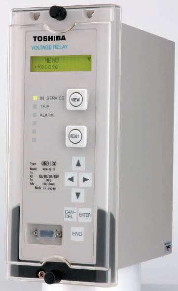
2 FEATURES Phase undervoltage protection with IDMTL or DTL. Phase overvoltage protection with IDMTL or DTL. Zero phase sequence overvoltage (neutral voltage displacement) protection with IDMTL/DTL. Negative phase sequence overvoltage protection with IDMTL or DTL. Programmable reset characteristics. Four settings groups. Configurable binary inputs and outputs. Circuit breaker condition monitoring. Trip circuit supervision. Automatic self-supervision. Menu-based HMI system. Configurable LED indication. Metering and recording functions. Communications for remote setting and data download is provided via the RSM (Relay Setting and Monitoring system. Front mounted RS232 serial port for local PC communications. Rear mounted RS485 or fibre optic serial port for remote PC communications. IEC protocol and Modbus protocol provided for serial communication APPLICATION The GRD130 is a range of fully numeric voltage protection relays. GRD130 has two models which differ according to the number of voltage inputs fitted, see Table 1. Model GRD GRD Table 1 - GRD130 Models Configuration 2 pole 4 pole Both models include multiple, high accuracy, phase under/overvoltage protection with inverse time and definite time delay functions. Voltage inputs can be configured for phase to phase or phase to neutral operation. Zero sequence overvoltage (neutral voltage displacement) protection is available for detection of earth faults in high impedance earthed or isolated systems. For protection against operation on unbalanced supply voltages, negative phase sequence overvoltage protection is also available. The ZPS and NPS overvoltage protections are available depending on the model and on the configuration selected, see Table 2. GRD130 provides continuous monitoring of internal circuits and of software. External circuits are also monitored, by trip circuit supervision and CB condition monitoring features. A user-friendly HMI is provided through a backlit LCD, programmable LEDs, keypad and menu-based operating system. PC access is also provided, either for local connection via a front-mounted RS232 port, or for remote connection via a rear-mounted RS485 or fibre optic port. The communication system allows the user to read and modify the relay settings, and to access data gathered by the relay s metering and recording functions. Data available either via the relay HMI or communications ports includes the following functions. Metering Fault recording Event recording Disturbance recording (available via communications ports) Model Number Table 2 - GRD130 Features Configuration 1V ph-ph + V 0 1V ph-n + V 0 GRD V ph-ph 3V ph-n 3V ph-n + V 0 3V ph-ph + V 0 2V ph-ph + V 0 Phase O/V (IDMTL) 59 Phase O/V (DTL) 59 Phase U/V (IDMTL) 27 Phase U/V (DTL) 27 ZPS O/V (IDMTL) 59N - ZPS O/V (DTL) 59N - NPS O/V (IDMTL) 47 - NPS O/V (DTL) 47 - Trip circuit supervision Self supervision CB State Monitoring Trip Counter Alarm Multiple settings groups Metering Fault records Event records Disturbance records IEC Communication Modbus 2
3 PROTECTION FUNCTIONS Phase Overvoltage Protection GRD130 overvoltage protection provides three independent overvoltage thresholds. The first and second thresholds may be set for inverse time or definite time operation. The third threshold can be programmed for definite time operation. The first and second thresholds has a programmable reset feature, selectable for instantaneous or definite time operation. Each element gives outputs for alarm and trip, and each trip output can be inhibited by binary input. Phase Undervoltage Protection GRD130 undervoltage protection provides three independent undervoltage thresholds. The first and second thresholds may be set for inverse time or definite time operation. The third threshold can be programmed for definite time operation. The first and second thresholds has a programmable reset feature, selectable for instantaneous or definite time operation. Each element gives outputs for alarm and trip, and each trip output can be inhibited by binary input. An undervoltage blocking function prevents undervoltage tripping in the case of a dead line. Zero Phase Sequence Overvoltage Protection (ZPS) GRD130 provides ZPS protection with two independent overvoltage thresholds. The two thresholds may be set for inverse time or definite time operation. The two thresholds have a programmable reset feature, selectable for instantaneous or definite time operation. In the case of GRD , the zero sequence voltage, V 0 may either be calculated from the three measured phase voltages, or it may be measured directly in the form of the system residual voltage, typically using a five limb VT. In the case of GRD , the V 0 must be measured directly. The low voltage settings which may be applied make the ZPS element susceptible to any 3 rd harmonic component which may be superimposed on the input signal. Therefore, a 3 rd harmonic filter is provided to suppress such superimposed components. Each element gives outputs for alarm and trip, and each trip output can be inhibited by binary input. Negative Phase Sequence Overvoltage Protection (NPS) GRD130 provides NPS protection with two independent overvoltage thresholds. The two thresholds may be set for inverse time or definite time operation. The two thresholds have a programmable reset feature, selectable for instantaneous or definite time operation. Each element gives outputs for alarm and trip, and each trip output can be inhibited by binary input. Inverse Time Operate Curves Ov erv oltage Inv erse Time Curv es Undervoltage Inverse Time Curves ZPS, NPS Overvoltage Inverse Time Curves Operating Time (secs) TMS = 10 TMS = 5 TMS = 2 TMS = 1 Operating Time (secs) TMS = 10 TMS = 5 TMS = 2 Operating Time (secs) TMS = 10 TMS = 5 TMS = 2 TMS = Applied Voltage (x Vs) t = 1 xtms 1 Vs ( V ) TMS = t = 1 Applied Voltage (x Vs) ( V ) xtms Vs Applied Voltage (x Vs) t = 1 xtms 1 Vs ( V ) Figure 1 - IDMT curves for Overvoltage, Undervoltage and ZPS, NPS Overvoltage 3
4 MONITORING FUNCTIONS Trip Circuit Supervision The circuit breaker tripping control circuit can be monitored by a binary input. Figure 2 shows a typical scheme. When the trip circuit is complete, a small current flows through the binary input, the circuit breaker auxiliary contacts and the trip coil. This current flows for both the breaker open and closed conditions. +ve Trip Suppl y GRD110 Trip Output Binar y Input Circuit Breaker CB Aux. Contac ts CB Trip Coil -ve Trip Suppl y Figure 2 - Trip Circuit Supervision Scheme If the trip supply is lost or if a connection becomes open circuit then the binary input resets and a Trip Circuit Fail alarm is given in the form of an output contact operation and LCD or LED indication. Automatic Self-Supervision Automatic monitoring of internal circuits and software is provided. In the event of a failure being detected, the ALARM LED on the relay fascia is illuminated, the RELAY FAILURE binary output operates, and the date and time of the failure is recorded in the event record. Circuit Breaker State Monitoring If two binary inputs are programmed to the functions CB OPEN and CB CLOSED then the CB State Monitoring function becomes active. In normal circumstances these inputs are in opposite states. If both show the same state then a CB Defective alarm is raised. Trip Counter Alarm The trip counter increments the number of tripping operations performed, and an alarm is issued when the count exceeds a user-defined setting. The trip count is triggered each time a trip is issued, and they can also be triggered by an external device via a binary input. METERING AND RECORDING Metering The following data is continuously available on the relay fascia LCD and at a local or remote PC. Primary and secondary voltages for each input. Positive and negative phase sequence voltages. Power frequency. CB trip count. CB status. Relay element output status. Binary input and output status. Event Record Records are stored for the 480 most recent events, time-tagged to 1ms resolution. The event record is available on the relay fascia LCD and at a local or remote PC. Events are recorded as follows: Tripping operations. Alarms. Operation of protection elements. Change of state of binary inputs / outputs. Change of relay setting. Failure detected by automatic supervision. Fault Record A relay trip initiates fault recording. Records are stored for the 8 most recent faults, time-tagged to 1ms resolution. The fault record is available on the relay fascia LCD and at a local or remote PC. Fault records include the following data: Date and time of trip operation. Faulted phase. Protection element responsible for trip. Measured voltage data. Disturbance Record The relay can record 4 analog and 32 binary signals, initiated by relay tripping. The post-trigger recording time can be set, and the maximum number of records which can be stored is dependent on the recording time chosen. Date and Time GRD130 provides a date and time feature for tagging of records. 4
5 USER INTERFACE Relay Front Panel A user friendly interface is provided on the relay front panel. A menu-based system provides for easy programming of relay functions and access to realtime and stored data. The front panel includes the following features. 16 character, 2-line LCD with backlight. 6 LEDs. Keypad. RS232C serial port for connection of local PC. Local PC Connection The user can communicate with the GRD130 from a local PC via the RS232C port on the front panel. Using RSM100 software, the user can view and modify settings, monitor real-time metering and analyse recorded data. Relay Setting and Monitoring (RSM) GRD130 can be connected to the RSM system via the rear mounted serial communications port, using either RS485 or fibre optic connections (specified at time of order). Using RSM100 software, the user can view and modify settings, monitor real-time metering and analyse recorded data. A maximum of 32 x 8 relays can be connected to the remote PC in multi-drop mode, by connection via a protocol converter G1PR2, with a maximum data transmission rate of 64kbps. The G1PR2 can be provided with maximum 8 ports and each port supports maximum 32 relays addressing. Protocol converter G1PR2 Figure 3 - Relay Setting and Monitoring System Figure 3 and 4 show the configuration of the RSM system and typical displays from the RSM100 software. Serial Communication GRD110 supports Modbus protocol and IEC protocol for communication with a substation control and monitoring system used to transfer measurand data, status data and general commands between the relay and the control system. Relay Setting The user can modify relay settings either using the front panel keypad or using the RSM100 software from a local or remote PC. Password protection is available for added security. Four settings groups are provided, allowing the user to set one group for normal conditions, while the other groups may be set to cover alternative operating conditions. Using the RSM software, the user can create a settings file on a PC (without being connected to a relay), and store the file ready for download to a relay at a later date. Binary Outputs GRD130 provides eight binary output contacts for tripping and alarm, of which seven are user programmable. Each of the programmable binary outputs is driven via a logic gate which can be programmed for OR gate or AND gate operation. Further, each output has a programmable reset characteristic, settable for instantaneous drop-off, delayed drop-off, or for latching operation. If latching operation is selected then an operated relay must be reset by the user, either by pressing the RESET button, by energising a binary input which has been programmed for Remote Reset operation, or by a communications command. Binary Inputs GRD130 provides eight programmable binary inputs. Each binary input is individually user-programmable for normal or inverted operation and for delayed pickup and/or drop-off. Each input can also be used to switch relay operation to a different settings group. General purpose alarm functions are also included. The user can define a text message for each alarm. Then when inputs associated with that alarm are raised, the defined text is displayed on the LCD. 5


6 PC DISPLAY Setting Event record Metering Fault record Figure 4 - Relay Setting and Monitoring System - PC Displays 6
7 TECHNICAL DATA Ratings AC voltage V n : 110V Frequency: 50Hz or 60Hz DC auxiliary supply: 110/125Vdc (Operative range: Vdc) 220/250Vdc (Operative range: Vdc) 48/54/60Vdc (Operative range: Vdc) Superimposed AC ripple on DC supply: maximum 12% DC supply interruption: maximum 50ms at 110V Binary input circuit DC voltage: 110/125Vdc (Operative range: Vdc) 220/250Vdc (Operative range: Vdc) 48/54/60Vdc (Operative range: Vdc) Overload Ratings AC voltage inputs: 2 times rated voltage continuous Burden AC phase voltage inputs: 0.1VA (at rated voltage) DC power supply: 10W (quiescent), 15W (maximum) Binary input circuit: 0.5W per input at 110Vdc Overvoltage Protection 1 st, 2 nd, 3 rd Overvoltage thresholds: OFF, V in 0.1V steps Delay type (1 st threshold only): DTL, IDMTL IDMTL Time Multiplier Setting TMS: in 0.01 steps DTL delay: Inst, s in 0.01s steps DO/PU ratio 10-98% in 1% steps Reset Delay (1 st threshold only): Instantaneous, s in 0.1s steps Undervoltage Protection 1 st, 2 nd, 3 rd Undervoltage thresholds: OFF, V in 0.1V syeps Delay type (1 st threshold only): DTL, IDMTL IDMTL Time Multiplier Setting TMS: in 0.01 steps DTL delay: Inst, s in 0.01s steps Reset Delay (1 st threshold only): Instantaneous, s in 0.1s steps Zero Sequence Overvoltage (ZPS) Protection 1 st, 2 nd ZPS Overvoltage thresholds: OFF, V in 0.1V steps Delay type (1 st threshold only): DTL, IDMTL IDMTL Time Multiplier Setting TMS: in 0.01 steps DTL delay: Inst, s in 0.01s steps Reset Delay (1 st threshold only): Instantaneous, s in 0.1s steps Negative Sequence Overvoltage (NPS) Protection 1 st, 2 nd NPS Overvoltage thresholds: OFF, V in 0.1V steps Delay type (1 st threshold only): DTL, IDMTL IDMTL Time Multiplier Setting TMS: in 0.01 steps DTL delay: Inst, s in 0.01s steps Reset Delay (1 st threshold only): Instantaneous, s in 0.1s steps Accuracy IDMTL Overvoltage Pick-up: 105% of setting ± 5% All Other Overvoltage Pick-ups: 100% of setting ± 5% Overvoltage PU/DO ratio: 95% (settable for phase overvoltage) IDMTL Undervoltage Pick-up: 95% of setting ± 5% All Other Undervoltage Pick-ups: 100% of setting ± 5% Undervoltage PU/DO ratio: 105% Inverse Time Delays: ± 5% or 30ms Definite Time Delays: ± 1% or 10ms 7
8 Front Communication port - local PC (RS232) Connection: Point to point Cable type: Multi-core (straight) Cable length: 15m (max.) Connector: RS232C 9-way D-type female Rear Communication port - remote PC (RS485) Connection: Multidrop (max. 32 relays) Cable type: Twisted pair Cable length: 1200m (max.) Connector: Screw terminals Isolation: 1kVac for 1 min. Transmission rate: 64kpbs for RSM system 9.6, 19.2kbps for IEC Rear Communication port - remote PC (Fibre Optic for IEC : option) Connection: Multidrop (max. 32 relays) Cable type: 50/125 or 62.5/125μm fibre Cable length: 1000m (max.) Connector: ST Transmission rate: 9.6, 19.2kbps for IEC Binary Inputs Operating voltage Typical 74Vdc(min. 70Vdc) for 110V/125Vdc rating Typical 138Vdc(min. 125Vdc) for 220V/250Vdc rating Typical 31Vdc(min. 28Vdc) for 48V/54V/60Vdc rating Binary Outputs Number 8 Ratings: Make and carry: 4A continuously Make and carry: 20A, 220Vdc for 0.5s (L/R 5ms) Break: 0.1A, 220Vdc (L/R=40ms) or 0.2A, 110Vdc (L/R=40ms) Durability: Loaded contact: operations Unloaded contact: operations Mechanical design Weight 4.5kg Case color Munsell No. 10YR8/0.5 Installation Flush mounting ENVIRONMENTAL PERFORMANCE Test Standards Details Atmospheric Environment Temperature IEC /2 Operating range: -10 C to +55 C. Storage / Transit: -25 C to +70 C. Humidity IEC days at 40 C and 93% relative humidity. Enclosure Protection IEC60529 IP51 (Rear: IP20) Mechanical Environment Vibration IEC Response - Class 1 Endurance - Class 1 Shock and Bump IEC Shock Response Class 1 Shock Withstand Class 1 Bump Class 1 Seismic IEC Class 1 8
9 Test Standards Details Electrical Environment Dielectric Withstand IEC kVrms for 1 minute between all terminals and earth. 2kVrms for 1 minute between independent circuits. 1kVrms for 1 minute across normally open contacts. High Voltage Impulse IEC Three positive and three negative impulses of 5kV(peak), 1.2/50μs, 0.5J between all terminals and between all terminals and earth. Electromagnetic Environment High Frequency Disturbance / Damped Oscillatory Wave Electrostatic Discharge Radiated RF Electromagnetic Disturbance Fast Transient Disturbance Surge Immunity Conducted RF Electromagnetic Disturbance Power Frequency Disturbance Conducted and Radiated Emissions IEC Class 3, IEC / EN IEC Class 3, IEC / EN IEC Class 3, IEC / EN IEC , IEC / EN IEC , IEC / EN IEC Class 3, IEC / EN IEC , IEC / EN IEC , EN55022 Class A, IEC / EN European Commission Directives 89/336/EEC 73/23/EEC 1MHz 2.5kV applied to all ports in common mode. 1MHz 1.0kV applied to all ports in differential mode. 6kV contact discharge, 8kV air discharge. Field strength 10V/m for frequency sweeps of 80MHz to 1GHz and 1.7GHz to 2.2GHz. Additional spot tests at 80, 160, 450, 900 and 1890MHz. 4kV, 2.5kHz, 5/50ns applied to all inputs. 1.2/50μs surge in common/differential modes: HV ports: 4kV/2kV (peak) PSU and I/O ports: 2kV/1kV (peak) RS485 port: 1kV/0.5kV (peak) 10Vrms applied over frequency range 150kHz to 100MHz. Additional spot tests at 27 and 68MHz. 300V 50Hz for 10s applied to ports in common mode. 150V 50Hz for 10s applied to ports in differential mode. Not applicable to AC inputs. Conducted emissions: 0.15 to 0.50MHz: <79dB (peak) or <66dB (mean) 0.50 to 30MHz: <73dB (peak) or <60dB (mean) Radiated emissions (at 30m): 30 to 230MHz: <30dB 230 to 1000MHz: <37dB Compliance with the European Commission Electromagnetic Compatibility Directive is demonstrated according to EN and EN Compliance with the European Commission Low Voltage Directive is demonstrated according to EN and EN
10 ORDERING Under/Overvoltage Relay GRD130 A 0 Type: Under/Overvoltage Relay GRD130 Model: Two pole 210 Four pole 410 Frequency: 50Hz 1 60Hz 2 DC auxiliary supply rating: 110V/125V 1 220V/250V 2 48V/54V/60V 3 24V/30V 4 Rear communication port: RS485 1 Dual RS485 3 RS485 + Fibre optic 9 10
11 TYPICAL APPLICATIONS / CONNECTIONS A B C BI1 COMMAND BI2 COMMAND BI3 COMMAND BI4 COMMAND BI5 COMMAND BI6 COMMAND BI7 COMMAND BI8 COMMAND (P) T FRAME EARTH T- A2 A4 B4 A5 B5 A6 B6 A7 B7 A8 B8 BI1 BI2 BI3 BI4 BI5 BI6 BI7 BI8 V Δ V N BO1 BO2 BO3 BO4 BO5 BO6 BO7 T- B4 A4 A5 B5 A7 B7 A6 B6 B8 A8 A9 B OUTPUT CONTACTS SIGNAL LIST (DEFAULT) BO1 GENERAL TRIP BO2 GENERAL TRIP BO3 GENERAL TRIP BO4 GENERAL TRIP BO5 UV1 TRIP BO6 UV1 TRIP BO7 ZPS1 TRIP (N) FAIL DC RELAY FAIL. 1 DD FAIL. T- A9 +5Vdc (+) DC-DC (-) B9 0V 0 0 FRAME EARTH COM1-A COM1-B COM1-0V OPT1 TX RX T-A2 Fibre optic I/F for IEC (Fibre optic model only: option) RS485 I/F for RSM, IEC E CASE EARTH COM2-A TB4-A2 COM2-B COM2-0V RS485 I/F for IEC (Two ports model only) This connection is connected by short bar before shipment. Figure 5 - GRD Typical Application Diagram for Single Phase-to-Phase Voltage and Direct Neutral Connection 11
12 A B C BI1 COMMAND BI2 COMMAND BI3 COMMAND BI4 COMMAND BI5 COMMAND BI6 COMMAND BI7 COMMAND BI8 COMMAND (P) T FRAME EARTH T- A2 A4 B4 A5 B5 A6 B6 A7 B7 A8 B8 BI1 BI2 BI3 BI4 BI5 BI6 BI7 BI8 V AB V BC BO1 BO2 BO3 BO4 BO5 BO6 BO7 T- B4 A4 A5 B5 A7 B7 A6 B6 B8 A8 A9 B OUTPUT CONTACTS SIGNAL LIST (DEFAULT) BO1 GENERAL TRIP BO2 GENERAL TRIP BO3 GENERAL TRIP BO4 GENERAL TRIP BO5 UV1 TRIP BO6 UV1 TRIP BO7 ZPS1 TRIP (N) FAIL DC RELAY FAIL. 1 DD FAIL. T- A9 +5Vdc (+) DC-DC (-) B9 0V 0 0 FRAME EARTH COM1-A COM1-B COM1-0V OPT1 TX RX T-A2 Fibre optic I/F for IEC (Fibre optic model only: option) RS485 I/F for RSM, IEC E CASE EARTH COM2-A TB4-A2 COM2-B COM2-0V RS485 I/F for IEC (Two ports model only) This connection is connected by short bar before shipment. Figure 6 - GRD Typical Application Diagram for Two Phase-to-Phase Voltage Connection 12
13 B C BI1 COMMAND BI2 COMMAND BI3 COMMAND BI4 COMMAND BI5 COMMAND BI6 COMMAND BI7 COMMAND BI8 COMMAND (P) T FRAME EARTH T- A2 A4 B4 A5 B5 A6 B6 A7 B7 A8 B8 BI1 BI2 BI3 BI4 BI5 BI6 BI7 BI8 V A V B V C V N BO1 BO2 BO3 BO4 BO5 BO6 BO7 T- B4 A4 A5 B5 A7 B7 A6 B6 B8 A8 A9 B OUTPUT CONTACTS SIGNAL LIST (DEFAULT) BO1 GENERAL TRIP BO2 GENERAL TRIP BO3 GENERAL TRIP BO4 GENERAL TRIP BO5 UV1 TRIP BO6 UV1 TRIP BO7 ZPS1 TRIP (N) FAIL DC RELAY FAIL. 1 DD FAIL. T- A9 +5Vdc (+) DC-DC (-) B9 0V 0 0 FRAME EARTH COM1-A COM1-B COM1-0V OPT1 TX RX T-A2 Fibre optic I/F for IEC (Fibre optic model only: option) RS485 I/F for RSM, IEC E CASE EARTH COM2-A TB4-A2 COM2-B COM2-0V RS485 I/F for IEC (Two ports model only) This connection is connected by short bar before shipment. Figure 7 - GRD Typical Application Diagram for Three Phase to Neutral Voltage Connection (Derived Zero Sequence Quantity) 13
14 A B C BI1 COMMAND BI2 COMMAND BI3 COMMAND BI4 COMMAND BI5 COMMAND BI6 COMMAND BI7 COMMAND BI8 COMMAND (P) T- A2 A4 B4 A5 B5 A6 B6 A7 B7 A8 B8 T FRAME EARTH BI1 BI2 BI3 BI4 BI5 BI6 BI7 BI8 V AB V BC V CA V N BO1 BO2 BO3 BO4 BO5 BO6 BO7 T- B4 A4 A5 B5 A7 B7 A6 B6 B8 A8 A9 B OUTPUT CONTACTS SIGNAL LIST (DEFAULT) BO1 GENERAL TRIP BO2 GENERAL TRIP BO3 GENERAL TRIP BO4 GENERAL TRIP BO5 UV1 TRIP BO6 UV1 TRIP BO7 ZPS1 TRIP (N) FAIL DC RELAY FAIL. 1 DD FAIL. T- A9 +5Vdc (+) DC-DC (-) B9 0V 0 0 FRAME EARTH COM1-A COM1-B COM1-0V OPT1 TX RX T-A2 Fibre optic I/F for IEC (Fibre optic model only: option) RS485 I/F for RSM, IEC E CASE EARTH COM2-A TB4-A2 COM2-B COM2-0V RS485 I/F for IEC (Two ports model only) This connection is connected by short bar before shipment. Figure 8 - GRD Typical Application Diagram for Two Phase VT Connection with Residual Voltage Measured by Earthing Transformer 14
15 RELAY OUTLINE IN SER VIC E VIEW TRIP ALARM RESET A B 0V CAN CEL ENTER END 104 Front view Side view 4 holes-φ4.5 4 holes-φ5.5 T TB4 T OPT1 TX T RX T T T E E Rear view for Dual RS485 Model T T TB4 T Rear view for Fibre optic Model Terminal Application T: RS485 I/F (CH1) for RSM TB4 RS485 I/F (CH2) for IEC OPT1 Fibre optic for IEC Panel cut-out 0 0 T,T,T: Screw terminal (M3.5 Ring) TB4: Screw terminal for Dual RS485 Model only OPT1: ST connector for Fibre optic Model only 8 Terminal block 8 Figure 9 - GRD130 Outline Diagram 15
16 72-34, Horikawa-cho, Saiwai-ku, Kawasaki , Japan Tel Fax The data given in this catalog are subject to change without notice.
GRE130. Protection and Control for MV Systems
 Protection and Control for MV Systems FEATURES Phase undervoltage protection with IDMTL or DTL(27). Phase overvoltage protection with IDMTL or DTL(59). Zero phase sequence overvoltage (neutral voltage
GRD110 FEATURES APPLICATION
 FEATURES Overcurrent protection for phase and earth faults with IDMTL or DTL. Three instantaneous elements with DTL. Programmable reset characteristics. Sensitive earth fault protection (SEF). Restricted
Table 1 Relay Model and Function
 FEATURES Numerical autoreclosing function Single-shot, single-phase and/or three-phase autoreclose scheme for one or two circuit breakers Multi-shot (selectable between 2 and 4) threephase autoreclose
GRE120. Motor Protection and Control for MV Systems
 Motor Protection and Control for MV Systems FEATURES Overcurrent protection for phase and earth faults (50/51P, 50/51N). Dependent and independent time characteristics (IDMTL and DTL). Restricted earth
INSTRUCTION MANUAL TRIP CIRCUIT SUPERVISION RELAY GKAD1
 INSTRUCTION MANUAL TRIP CIRCUIT SUPERVISION RELAY GKAD1 TOSHIBA Corporation 2004 All Rights Reserved. ( Ver. 1.6 ) Safety Precautions Before using this product, please read this chapter carefully. This
GRT100 FEATURES APPLICATION
 FEATURES Fully numerical transformer protection Current differential protection for two-winding or three-winding transformers High-set differential overcurrent protection No interposing CTs required CT
GRD150. FEATURES Protection functions. Control functions. Monitoring and Metering. Recording. User Interface APPLICATION
 FEATURES Protection functions Non-directional and directional overcurrent and earth-fault protection and sensitive earth fault protection (option) Overvoltage and undervoltage protection Thermal overload
Type MVTT 14 and MVTT 15: Static Digital Time delay relays
 Type MVTT 4 and MVTT 5: Static Digital Time delay relays Features 000/ setting range Time settings easily selected by means of thumbwheel switches Provide time delayed pick-up, or drop-off Compact construction
GRE110. Protection and Control for MV Systems
 Protection and Control for MV Systems FEATURES Overcurrent protection for phase and earth faults (50/5P, 50/5N). Dependent and independent time characteristics (IDMTL and DTL). Four independent current
Combined Overcurrent and Earth-fault Relay SPAJ 140 C. Product Guide
 Combined Overcurrent and Earth-fault Product Guide Issued: April 1999 Status: Updated Version: C/18.04.2006 Data subject to change without notice Features Three-phase, low-set phase overcurrent unit with
GRE160. Transformer Protection
 Transformer Protection FEATURES Fully numerical transformer protection Current differential protection for two-winding transformers with inrush restraint (87T) High-set differential overcurrent protection
Reyrolle Protection Devices. 7SG118 Argus 8 Voltage & Frequency Relay. Answers for energy
 Reyrolle Protection Devices 7SG118 Argus 8 Voltage & Frequency Relay Answers for energy 7SG118 Argus 8 Voltage and Frequency Relay Data Storage and Communication Serial communications conform to IEC60870-5-103
General catalog. Copyright 2017 Toshiba Energy Systems & Solutions Corporation. All rights reserved.
 General catalog 72-34, Horikawa-cho, Saiwai-ku, Kawasaki 212-8585, Japan Tel +81-44-331-1462 Fax +81-44-548-9540 http://www.toshiba-relays.com - The information provided in this catalog is subject to change
Sensitive definite time or inverse time earth-fault stage for back-up residual earthfault
 Issued: April 1999 Status: Updated Version: B/09.11.2001 Data subject to change without notice Features Sensitive restricted earth-fault protection stage for fast, selective earth-fault protection Sensitive
Earth-fault Relay SPAJ 110 C. Product Guide
 Issued: April 1999 Status: Updated Version: C/12.04.2006 Data subject to change without notice Features Low-set neutral overcurrent stage with definite time or inverse time characteristic High-set neutral
Reyrolle Protection Devices. 7SG117 Argus 7 Synchronising Relay. Answers for energy
 Reyrolle Protection Devices 7SG117 Argus 7 Synchronising Relay Answers for energy 7SG117 Argus 7 Synchronising Relay Fig 1. Independent check & system synchronising settings Adjustable slip frequency,
General catalog. Energy Systems & Solutions Company A2. Copyright 2017 Toshiba. All rights reserved.
 General catalog Energy Systems & Solutions Company 72-34, Horikawa-cho, Saiwai-ku, Kawasaki 212-8585, Japan Tel +81-44-331-1462 Fax +81-44-548-9540 http://www.toshiba-relays.com - The information provided
Protection Relays PHASE & RESIDUAL OVERCURRENT
 Protection Relays PHASE & RESIDUAL OVERCURRENT Application The relay type NA016 can be used in radial networks as feeder or power transformer protection. In solidly grounded systems the residual overcurrent
Residual overvoltage relay
 Page 1 Issued: April 1999 Status: New Data subject to change without notice Features Definite-time residual overvoltage earthfault protection and supervision Two independent operation stages, e.g. one
Bus Bar Protection Relay B-PRO 4000
 Bus Bar Protection Relay B-PRO 4000 Product Overview The IEC 61850 station bus embedded B-PRO 4000 relay provides complete bus and substation differential protection (low impedance) with CT saturation
Feeder protection relay SPAA 121 C. Product Guide
 Issued: April 1999 Status: Updated Version: C/06.03.2006 Data subject to change without notice Features Two-phase low-set phase overcurrent unit with definite time or inverse time characteristic Two-phase
GRE140. Protection and Control for MV Systems
 Protection and Control for MV Systems FEATURES Four stage non-directional and directional overcurrent protection for phase and earth faults with IDMTL or DTL. Polarizing voltage memory. Directional earth
Combined Overcurrent and Earth-fault Relay SPAJ 141 C. Product Guide
 Combined Overcurrent and Earth-fault Product Guide Issued: April 1999 Status: Updated Version: C/19.04.2006 Data subject to change without notice Features Three-phase, low-set phase overcurrent unit with
Relion 611 series. 611 series Type Test Certificate
 Relion 611 series 611 series Document ID: 1MRS757466 Issued: 2016-02-22 Revision: B Product version: 2.0 Copyright 2016 ABB. All rights reserved Table of contents Table of contents Section 1 Section
7SR158 Argus Voltage and Frequency Relay Energy Management.
 Reyrolle Protection Devices 7SR158 Argus Voltage and Frequency Relay Energy Management. Siemens Protection Devices Limited 2 7SR158 Argus Voltage & Frequency Relay User Interface 20 Character x 4 Line
Sensitive Earth-fault Relay SPAJ 111 C. Product Guide
 Issued: April 1999 Status: Update Version: C/12.04.2006 Data subject to change without notice Features Sensitive low-set neutral overcurrent stage with definite time characteristic High-set neutral overcurrent
Directional or Non-Directional Earth-Fault Relay REJ 527. Product Guide
 Directional or Non-Directional Earth-Fault Product Guide Issued: 17.06.19994 Status: Updated Version: C/16.10.2002 Data subject to change without notice Features Directional or non-directional low-set
Feeder protection relay SPAA 341 C. Product Guide
 Issued: April 1999 Status: Updated Version: D/07.03.2006 Data subject to change without notice Features Comprehensive numerical feeder protection relay consisting of two multi-function protection relay
Relion 605 series. Self-powered feeder protection REJ603 Product Guide
 Relion 605 series Relion 605 series Relion 605 series Self-powered feeder protection Product Guide Product version: 3.0 Contents 1. Description... 3 2. Relay functions... 3 3. Protection functions... 4
Feeder protection relay
 Page 1 Issued: April 1999 Status: New Data subject to change without notice Features Comprehensive numerical feeder protection relay consisting of two multi-function protection relay modules and a flexible
7SR18 Solkor Line Differential Protection Energy Management
 Reyrolle Protection Devices 7SR18 Solkor Line Differential Protection Energy Management 7SR18 Solkor five or eight user-programmable binary output contacts and three or six user programmable status inputs
Single-phase ( V) voltage monitoring: Undervoltage Overvoltage Window mode (overvoltage + undervoltage) Voltage fault memory selectable
 voltage monitoring: Undervoltage Overvoltage Window mode (overvoltage + undervoltage) Voltage fault memory selectable") 70 Series - Line monitoring relay 70 Features 70.11 70.31 70.41 Electronic voltage monitoring relays for single and three-phase applications Multifunctional types, providing the flexibility of monitoring
70 Series - Line monitoring relay 70 Features 70.11 70.31 70.41 Electronic voltage monitoring relays for single and three-phase applications Multifunctional types, providing the flexibility of monitoring
Reyrolle Protection Devices. 7SG13 Delta Protection and Control Relays. Answers for energy
 Reyrolle Protection Devices 7SG13 Delta Protection and Control Relays Answers for energy 7SG13 Delta Protection and Control Relays User Interface 20 character x 2 line backlit LCD Menu navigation keys
For Transmission, Distribution and Machinery protection.
 Founded in 1953, Microelettrica Scientifica has developed a wide range of products, divided into three main lines: For Transmission, Distribution and Machinery protection. A-Line Electronic analogic. M-Line
Protection and control. Sepam range Sepam 100 RT. Merlin Gerin Square D Telemecanique
 Protection and control epam range epam T Merlin Gerin quare D Telemecanique presentation contents page presentation connection characteristics installation ordering information epam T. on in in in in in
Reyrolle Protection Devices. 7SR11 and 7SR12 Argus Overcurrent Relays. Answers for energy
 Reyrolle Protection Devices 7SR11 and 7SR12 Argus Overcurrent Relays Answers for energy 7SR11 and 7SR12 Argus Overcurrent Relays Control 79 Auto Reclose 86 Lockout CB Control Features Cold Load Settings
Arc protection relay. Features Three-phase overcurrent function. Application
 Arc protection relay REA 10_ Page 1 Issued: May 1999 Status: New Data subject to change without notice Features Three-phase overcurrent function Loop-type or radial sensor fibre for arc detection Two high-speed
IRI1-ES Sensitive Earth Fault Current Relay. Manual IRI1-ES (Revision A)
") IRI1-ES Sensitive Earth Fault Current Relay Manual IRI1-ES (Revision A) Woodward Manual IRI1-ES GB Woodward Governor Company reserves the right to update any portion of this publication at any time. Information
IRI1-ES Sensitive Earth Fault Current Relay Manual IRI1-ES (Revision A) Woodward Manual IRI1-ES GB Woodward Governor Company reserves the right to update any portion of this publication at any time. Information
SIPROTEC easy 7SJ45 Numerical Overcurrent Protection Relay Powered by CTs
 SIPROTEC easy 7SJ4 Numerical Overcurrent Protection Relay Powered by CTs Function overview Fig. /1 Description The SIPROTEC easy 7SJ4 is a numerical overcurrent protection relay which is primarily intended
Reyrolle Catalogue Answers for Energy
 Reyrolle Protection Devices Reyrolle Catalogue Answers for Energy Index Compact Overcurrent Argus C 7SR11 & 7SR12 1 Multifunction Overcurrent Argus M 7SR21 & 7SR22 2 Multifunction Reclose Controller Recloser
Communication Gateway COM 610. Product Guide
 Communication Gateway COM 610 Product Guide Issued: September 2004 Status: Updated Version: D/17.10.2006 Data subject to change without notice Features Protocol conversion gateway for substation automation:
General catalog AP. Copyright 2014 Toshiba. All rights reserved.
 General catalog 72-34, Horikawa-cho, Saiwai-ku Kawasaki-shi, Kanagawa 212-8585, Japan Tel +81-44-331-1462 Fax +81-44-548-9540 http://www.toshiba-relays.com - The information provided in this catalog is
RE17LAMW on-delay timing relay - 1 s..100 h V AC/ DC - solid state output
 Characteristics on-delay timing relay - 1 s..100 h - 24..240 V AC/ DC - solid state output Main Range of product Product or component type Discrete output type Width Component name Time delay type Time
7SR23 DAD High Impedance Protection Relay Energy Management
 Reyrolle Protection Devices 7SR23 DAD High Impedance Protection Relay Energy Management 2 Siemens Protection Devices Limited 7SR23 DAD High Impedance Relay User Interface 20 character x 4 line backlit
Voltage regulator. SPAU 341 C 1MRS MBG Issued: July 1998 Status: Revised Version: C/ Data subject to change without notice
 Issued: July 1998 Status: Revised Version: C/08.10.2003 Data subject to change without notice Features Comprehensive voltage regulation for power transformers with on-load tapchangers in distribution substations
RE17LCBM off-delay timing relay - control - 1 s..100 h V - solid state output
 Characteristics off-delay timing relay - control - 1 s..100 h - 24..240 V - solid state output Main Range of product Product or component type Discrete output type Width Component name Time delay type
Reyrolle Protection Devices. 7SR11 and 7SR12 Argus Overcurrent Relays. Answers for energy
 Reyrolle Protection Devices 7SR11 and 7SR12 Argus Overcurrent Relays Answers for energy 7SR11 and 7SR12 Argus Overcurrent Relays 74T/CCS Trip & Close Circuit Supervision 60VTS VT Supervision Control 79
Transformer Protection Relay
 Transformer Protection Relay T-PRO Product Overview The IEC 61850 station bus embedded T-PRO relay provides complete three-phase multi-winding transformer protection and overload protection, DFR-quality
7SR21 Non-Directional 7SR22 Directional Overcurrent Relay
 7SR21 Non-Directional 7SR22 Directional Overcurrent Relay Document Release History This document is issue 2010/05. The list of revisions up to and including this issue is: 2010/05 Additional Comms modules
TM221CE40R controller M IO relay Ethernet
 Characteristics controller M221 40 IO relay Ethernet Main Range of product Product or component type [Us] rated supply voltage Jan 6, 2019 Modicon M221 Logic controller 100...240 V AC Discrete input number
Synchro-check relay. Application
 Issued: April 1999 Status: Updated Version: B/08.11.2001 Data subject to change without notice Features Two identical operation stages allowing the closing conditions of two separate circuit breakers to
TM221M16TG controller M IO transistor PNP spring
 Characteristics controller M221 16 IO transistor PNP spring Main Range of product Product or component type [Us] rated supply voltage Discrete input number Analogue input number Discrete output type Discrete
BUSBAR. www. ElectricalPartManuals. com
 BUSBAR FATURS GR0 is a numerical low impedance differential relay for busbar protection. GR0 provides the following features. Discriminating zone and Check zone protection Maximum four zones Percentage
7SR11 and 7SR12 Argus Overcurrent Relays Answers for infrastructure & cities.
 Reyrolle Protection Devices 7SR11 and 7SR12 Argus Overcurrent Relays Answers for infrastructure & cities. 7SR11 and 7SR12 Argus Overcurrent Relays Supervision 60CTS CT Supervision 74T/CCS Trip & Close
PROTECTION RELAYS THE ULTRA LINE NUMERICAL MULTIFUNCTION INTELLIGENT DEVICE FOR PROTECTION, SUPERVISION, METERING AND CONTROL
 MICROPROCESSOR PROTECTION RELAYS THE ULTRA LINE NUMERICAL MULTIFUNCTION INTELLIGENT DEVICE FOR PROTECTION, SUPERVISION, METERING AND CONTROL MICROELETTRICA SCIENTIFICA MANUFACTURES A COMPLETE RANGE OF
RE17LAMW on-delay timing relay - 1 s..100 h V AC/DC - solid state output
 Characteristics on-delay timing relay - 1 s..100 h - 24..240 V AC/DC - solid state output Complementary Control type Voltage range Main Range of product Product or component type Discrete output type Width
NPW800R RETROFITTING. Power and Volatge Protection Relay
 RETROFITTING Power and Volatge Protection Relay NPW800R (R3 case) is dedicated to the refurbishment of CEE WTG 7000 relays (R3 case) providing the measurement of apparent (S), active (P) and reactive (Q)
INTRODUCTION. The PL-50 MO and PM-250 families represent the. PM-250-H: Horizontal box. PM-250-V: Vertical box
 INTRODUCTION The PL-50 MO units are available in the next mechanical version: The PL-50 MO and PM-250 families represent the different solutions that Team Arteche offers for motor protection. Both families
High-Tech Range IRI1-ES- Sensitive Earth Fault Current Relay
 High-Tech Range IRI1-ES- Sensitive Earth Fault Current Relay IE ON RESET.5 X1 t IE X1.6%.2.4.8 1.6 X1.1s.2.4.8 1.6 X2 OFF ON S1 S2 IRI1-ES IRI1-ES C&S Electric Limited (Protection & Control Division) Contents
TM221ME16T controller M IO transistor PNP Ethernet
 Characteristics controller M221 16 IO transistor PNP Ethernet Main Range of product Product or component type [Us] rated supply voltage Discrete input number Analogue input number Discrete output type
RT4B-110V/12A RECTIFIER
 The RT4B-110V/12A is a switched mode rectifier (SMR) module designed to provide up to 12A of output current into a 110V nominal system. It can be used with or without a cooling fan. With a fan it runs
Feeder Protection Relay REF 610. Product Guide
 Product Guide Contents 1 Description.............................. 3 2 Protection functions....................... 3 3 Measurement............................ 4 4 Disturbance recorder......................
TM221M16R controller M IO relay
 Product data sheet Characteristics TM221M16R controller M221 16 IO relay Complementary Main Discrete I/O number 16 Number of I/O expansion module Supply voltage limits Inrush current Power consumption
RT4F-110V/25A RECTIFIER
 The RT4F-110V/25A is a hot-pluggable switched mode rectifier (SMR) module designed to provide up to 25A of output current into a 110V nominal system. Examples of such systems are 60 cells lead acid (136V
RT4F-48V/50A-WAC RECTIFIER
 The RT4F-48V/50A-WAC is a switched mode rectifier (SMR) module designed to provide up to 58A of output current into a 48V nominal system, over a wide range of AC input voltage. This rectifier has been
TM221CE24R controller M IO relay Ethernet
 Product data sheet Characteristics TM221CE24R controller M221 24 IO relay Ethernet Complementary Main Discrete I/O number 24 Number of I/O expansion module Supply voltage limits Network frequency Inrush
Arc protection relay. Features Three-phase overcurrent function. Application
 Arc protection relay REA 10_ Issued: May 1999 Status: Updated Version: B/12.11.2001 Data subject to change without notice Features Three-phase overcurrent function Loop-type or radial sensor fibre for
Multi Function Protection IED
 Multi Function Protection IED GR-200 series - The GR-200 Series is Toshiba s next generation of protection and control IED s, designed for transmission/distribution networks and providing a platform for
TM221M32TK controller M IO transistor PNP
 Characteristics controller M221 32 IO transistor PNP Main Range of product Product or component type [Us] rated supply voltage Discrete input number Analogue input number Discrete output type Discrete
TM221ME32TK controller M IO transistor PNP Ethernet
 Product data sheet Characteristics TM221ME32TK controller M221 32 IO transistor PNP Ethernet Complementary Main Discrete I/O number 32 Number of I/O expansion module Supply voltage limits Inrush current
PowerLogic power-monitoring units. Power Meter PM500. Technical data sheet 2006
 PowerLogic power-monitoring units Technical data sheet 2006 Functions and characteristics E90463 The PowerLogic PM500 Power Meter provides all measurement capabilities required to monitor an electrical
Characteristics. Application RTU560. DIN Rail RTU 560CIG10. Data Sheet DIN Rail RTU 560CIG10
 DIN Rail RTU 560CIG10 Application The 560CIG10 is a DIN rail RTU560 consisting of a communication unit (CMU), a multi-i/o module (MIO) and a power supply (PSU) in a metal DIN rail housing. The essential
MiCOM P122C Time-Overcurrent Protection
 Protection Relays 01 MiCOM P122C Time-Overcurrent Protection Customer Benefits 1A/5A software setting 4 function keys Compact unit for flush and wall-surface mounting Comprehensive measurements Disturbance
7SR45 Argus 7SR45 Self Powered/Dual Powered Non-Directional Overcurrent and Earth Fault Relay
 7SR5 Argus 7SR5 Self Powered/Dual Powered Non-Directional Overcurrent and Earth Fault Relay Energy Management 7SR5 Argus 7SR5 Argus Self Powered/Dual Powered Non-Directional Overcurrent and Earth Fault
RT4F-120V/20A-WAC RECTIFIER
 The RT4F-120V/20A-WAC is a switched mode rectifier/charger module designed to provide up to 20A of output current into a 120V nominal system. This charger has been designed for use in conjunction with
TM221CE40T controller M IO transistor PNP Ethernet
 Product data sheet Characteristics TM221CE40T controller M221 40 IO transistor PNP Ethernet Complementary Main Discrete I/O number 40 Number of I/O expansion module Supply voltage limits Inrush current
TM221CE40R controller M IO relay Ethernet
 Product datasheet Characteristics TM221CE40R controller M221 40 IO relay Ethernet Main Range of product Product or component type [Us] rated supply voltage Discrete input number Analogue input number Discrete
Millenium 3. General Characteristics. General environment characteristics for CB, CD, XD, XR and XE product types
 Millenium 3 General Characteristics Millenium 3 Compact Range Millenium 3 Expandable Range Millenium 3 Communication Options Millenium 3 Range General environment characteristics for CB, CD, XD, XR and
TM221CE24T controller M IO transistor PNP Ethernet
 Characteristics controller M221 24 IO transistor PNP Ethernet Main Range of product Product or component type [Us] rated supply voltage Discrete input number Analogue input number Discrete output type
Reyrolle Protection Devices. 7SR210 & 7SR220 Argus Overcurrent Protection Relay. Answers for energy
 Reyrolle Protection Devices 7SR10 & 7SR0 Argus Overcurrent Protection Relay Answers for energy 7SR10 7SR0 Argus Overcurrent Protection Relay Additional Functionality 7SR0n Directional Relay 7/59 Under/Over
TM241C40U controller M IO transistor NPN
 Characteristics controller M241 40 IO transistor NPN Main Range of product Product or component type [Us] rated supply voltage 15/12/2018 Modicon M241 Logic controller 24 V DC Discrete input number 24
70 SERIES. Line monitoring relay
 70 SRIS 70 SRIS lectronic voltage monitoring relays for single and three-phase applications Multifunctional types, providing the flexibility of monitoring Undervoltage, Overvoltage, Window Mode, Phase
EM132 EM132. Main Features. Multi-functional 3-Phase Transducer. Energy Meter
 EM132 MULTI-FUNCTION TRANSDUCER SATEC EM132 is a Smart DIN Rail Multi-Function Transducer with a local display. It is based on SATEC s best seller PM130 PLUS with an off-the-shelf LCD display (similar
TM241C24T controller M IO transistor PNP
 Characteristics controller M241 24 IO transistor PNP Main Range of product Product or component type [Us] rated supply voltage Feb 13, 2018 Modicon M241 Logic controller 24 V DC Discrete input number 14
Universal Power Supplies
 , Features Universal input: 90 264 VAC or 120 30 VDC Active power factor correction (>0.95) High efficiency up to 93% Load share function for up to 3 units in parallel Adjustable output voltage EMI/EMC
SM100. On-Line Switchgear Condition Monitoring
 On-Line Switchgear Condition Monitoring On-Line Switchgear Condition Monitoring Introduction Weis is a specialist company with over 40 years of experience in the commissioning, testing & maintenance of
Type VRLTC tap changer
 Report No. 1ZUA938502-AGC 2, Rev 0 Date: 6 November 2012 Type VRLTC tap changer Ruggedized electronics systems specification & type test data Product Style No Rating By Type VRLTC, on-tank, vacuum reactance
TM221ME16T controller M IO transistor PNP Ethernet
 Product datasheet Characteristics TM221ME16T controller M221 16 IO transistor PNP Ethernet Main Range of product Product or component type [Us] rated supply voltage Modicon M221 Logic controller 24 V DC
TM241C40R controller M IO relay
 Characteristics controller M241 40 IO relay Main Range of product Product or component type [Us] rated supply voltage Mar 09, 2017 Modicon M241 Logic controller 100...240 V AC Discrete input number 24
www. ElectricalPartManuals. com Protective Relays HIGHLIGHTS PROTECTIVE FUNCTIONS ixp-420 Transformer Protection Relay
 Protective Relays Electrical Apparatus ixp-420 Transformer Protection Relay 165-420 Figure 1: Edison Idea Relay The ixp-420 is a member of Cooper Power Systems Edison Idea line of protective relays. The
- Control and monitoring of switchgear, transformers and other equipment or devices in EHV, HV, MV and LV substations
 Bay Control IED GR-200 series - The GR-200 Series is Toshiba s next generation of protection and control IED s, designed for transmission/distribution networks and providing a platform for distributed
RE11RAMU on-delay timing relay - 1 s..100 h V AC - 1 OC
 Characteristics on-delay timing relay - 1 s..100 h - 24..240 V AC - 1 OC Complementary Contacts material Width pitch dimension Control type Voltage range Connections - terminals Housing material Main Range
InteliPro. Protection Relay for Parallel Applications. Technical Specification
 InteliPro Protection Relay for Parallel Applications Product description InteliPro is a highly flexible interconnection/mains decoupling protective relay with extensive protective functions. It meets the
7SR242 Duobias Multi-Function 2-Winding Transformer Protection Relay
 7SR242 Duobias Multi-Function 2-Winding Transformer Protection Relay Document Release History This document is issue 2010/06. The list of revisions up to and including this issue is: 2010/06 Additional
TM3DI16 module TM3-16 inputs
 Characteristics module TM3-16 inputs Main Range of product Product or component type Range compatibility Jun 30, 2018 Modicon TM3 Discrete input module Modicon M241 Modicon M251 Modicon M221 Discrete input
PowerLogic power-monitoring units. PM1000 series power meter. Technical data sheet
 PowerLogic power-monitoring units power meter Technical data sheet 2011 Basic energy meters Functions and characteristics PE86261 PE86260 PowerLogic PM1000 power meter. The PowerLogic power meters are
RE48ATM12MW on-delay timing relay s..300 h V AC - 2 OC
 Characteristics on-delay timing relay - 0.02 s..300 h - 24..240 V AC - 2 OC Complementary Product front plate size Control type Housing material Main Range of product Product or component type Electrical
Scout-S Station Controller
 Scout-S Station Controller Substation Automation Scout-S Station Controller The Scout-S Station Controller is a SCADA enabled remote terminal unit (RTU) with a data concentrator, event reporter, and built-in
RE22R2AMR On-delay Timing Relay s 300h V AC/DC - 2C/O
 Characteristics On-delay Timing Relay - 0.05s 300h - 24 240V AC/DC - 2C/O Main Range of product Product or component type Discrete output type Device short name Nominal output current Complementary Contacts