Application Suggestions for X2Y Technology
|
|
|
- Jodie Todd
- 5 years ago
- Views:
Transcription
1 Application Suggestions for X2Y Technology The following slides show applications that would benefit from balanced, low inductance X2Y devices. X2Y devices can offer a significant performance improvement and lower costs through component removal and PC board area reduction. 1
2 Index X2Y Schematic.. Slide 3 Mounting Pad Layout Slide 4 X2Y Attachment Examples Slide 5-7 APPLICATIONS Micro-power Instrumentation Amplifier.. Slide 9-11 Transceiver Slide 12,13 Can Bus. Slide Crystal Circuit.. Slide Hall Effect Sensor Slide LED Circuit Slide Connectors (reduce pin count).. Slide Multi PC Board Systems.. Slide Bulk Capacitance for Switching Power Supplies Audio Amplifiers. Comments and Questions Slide Slide Slide 31 2
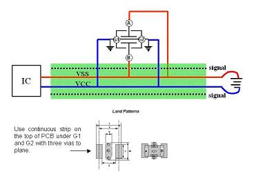
3 X2Y Schematic The X2Y component will be represented in these notes by the following two circuit schematics. A G1 G1 G2 A B G2 B 3
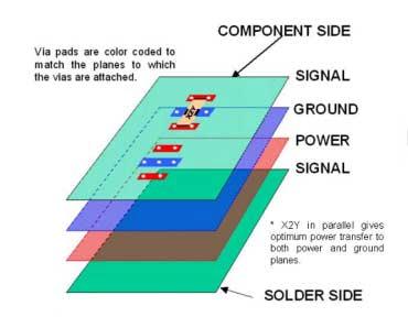
4 Mounting Pad Layout The land pattern required for using X2Y on a PCB board is the same for all illustrated applications. A continuous pad under the G1 and G2 terminations with two minimum vias to the board plane is crucial for optimum performance. Further details for grounding and attachment are at this link: Land Pattern Board View A X G1 X2Y G2 B Y A G2 B Front Board Surface Ground Plane A Board Surface Ground Plane Side 4

5 X2Y Attachment Examples REFERENCE PLANE 5
6 X2Y Attachment Examples 6

7 X2Y Attachment Examples 7
8 Applications 8
9 Micro-power Instrumentation Amplifier Standard Filter Suggestion Standard Components:! 7 regular capacitors are required for filtering, which consumes board space and raises placement costs.! Expensive tight tolerance capacitors are required for good circuit function.! Capacitors C1 and C2 need to be ± 5% tolerance devices to avoid degrading the circuit's common mode rejection. 1. The circuit should be built using a PC board with a ground plane one both sides. 2. All component leads should be as short as possible. 3. Resistors R1 and R2 can be common 1% metal film units 4. Capacitors C1 and C2 need to be ± 5% tolerance devices to avoid degrading the circuit's common mode rejection. 5. Either the traditional 5% Silver mica units or Panasonic ± 2% PPS film capacitors are recommended. 1 Analog Devices application notes, 9
10 Micro-power Instrumentation Amplifier X2Y Filter Suggestion, Option 1 X2Y Benefits: Both High and low cap values are needed for broad frequency filtering.! 3 regular capacitors are replaced with a single X2Y, which saves board space and lowers placement costs.! A single X2Y replaces the expensive Mica or Film tight tolerance capacitors. A G1 G2 R G B 1. The circuit should be built using a PC board with a ground plane one both sides. 2. All component leads should be as short as possible. 3. Resistors R1 and R2 can be common 1% metal film units 4. Capacitors C1 and C2 need to be ± 5% tolerance devices to avoid degrading the circuit's common mode rejection. 5. Either the traditional 5% Silver mica units or Panasonic ± 2% PPS film capacitors are recommended. 1 Analog Devices application notes, 10
11 Micro-power Instrumentation Amplifier X2Y Filter Suggestion, Option 2 X2Y Benefits:! 7 regular capacitors are replaced with a two X2Ys, which saves board space and lowers placement costs.! A single X2Y replaces the expensive Mica or Film tight tolerance capacitors. Remove A Single X2Y across the two power pins removes 4 capacitors and has broad has broad frequency effectiveness. 1. The circuit should be built using a PC board with a ground plane one both sides. 2. All component leads should be as short as possible. 3. Resistors R1 and R2 can be common 1% metal film units 4. Capacitors C1 and C2 need to be ± 5% tolerance devices to avoid degrading the circuit's common mode rejection. 5. Either the traditional 5% Silver mica units or Panasonic ± 2% PPS film capacitors are recommended. 1 Analog Devices application notes, Remove 11
12 Transceiver Standard Filter Suggestion Standard Components:! Regular capacitors are in series and have narrow operating bandwidth.! Series feed thru type components with DC resistance can introduce voltage drop V_BIDI MONITOR RECEIVER LASER 3 5V_BIDI 0.1uF 0603 C2 1 C1 0.1uF CASE 1. Filtering across the diodes to reduce noise emissions. 2. Place filter components close to pins. 3. Low capacitance to prevent signal distortion 12
13 Transceiver X2Y Filter Suggestion X2Y Benefits: 1. X2Y is as close to the pins as possible. 2. A & B go across the diode. 3. Both G1 and G2 go to case/board ground. 4. Continuous trace under G1 & G2. 5. Connection to case ground should be short (low inductance). 1. Filtering across the laser and receiver diode to reduce noise emissions. 2. Place filter components close to pins. 3. Low capacitance to prevent signal distortion Note: Low capacitance value should be used so Signal is not affected. 13
14 Can Bus Standard Filter Suggestion Standard Components: 1. Three expensive components required ( 1 common mode choke and two cap varistors). 2. Uses more board space than a single cap solution Can 2 CAN_H CAN_H CAN ISSUES 1. EMC: Radiated emissions 2. Most existing CAN applications do not allow much capacitance 3. Problems in AM and/or FM band 4. Use common mode choke CAN_L CAN_L * Common Mode Choke: 51 uh rated inductance; 2 uh stray inductance; 0.3 ohm DC; 0.5 amp 14
15 Can Bus X2Y Filter Suggestion REMOVE X2Y Advantages: 1. One capacitor required 2. Uses less board space 3. X2Y functions over a much broader frequency spectrum Can 2 GND G1 A G2 100pf Vcc B CAN ISSUES 1. EMC: Radiated emissions 2. Most existing CAN applications do not allow much capacitance 3. Problems in AM and/or FM band 4. Use common mode choke * Common Mode Choke: 51 uh rated inductance; 2 uh stray inductance; 0.3 ohm DC; 0.5 amp 15
16 Crystal Circuit Standard Filter Suggestion Standard Components: 1. Two closely matched capacitance tolerance components are needed for best balancing of the crystal circuit. 2. Two caps Uses more board space than a single cap solution 1. Place component close to Crystal 2. Use surface mount components leads or traces should be as short as possible 3. Balanced capacitance for best function 16
17 Crystal Circuit X2Y Filter Suggestion X2Y Advantages: 1. One capacitor required 2. Uses less board space 3. One closely balanced X2Y can provider better balance the Crystal Circuit 4. X2Y functions over a much broader frequency spectrum Place component close to Crystal 2. Use surface mount components leads or traces should be as short as possible 3. Balanced capacitance for best function 17
18 Hall Effect Sensor Standard Filter Suggestion Standard Components: 1. Some circuits require two standard caps. 2. Two standard caps give poor common mode filtering. A VS Hall Sensor Q B GND 18
19 Hall Effect Sensor X2Y Filter Suggestion X2Y Advantages: 1. Single X2Y cap. 2. Balanced and improved common mode filtering 3. Differential mode filtering also provided 4. X2Y has <ns response time to ESD A VS Hall Sensor Q B GND G1 A B G2 19
20 LED Fast switching LED s can introduce common mode noise into a circuit and raise overall radiated and conducted emissions. 5V R 220 R 220 R 220 LED Typical LED circuit with a series limiting resistor 1 1 Sirius microsytems, 20
21 LED Standard Filter Suggestion Standard Components: 1. Requires two standard caps. 2. Two standard caps give poor common mode filtering 3. Single standard X capacitor is a narrow band filter element. 5V R 220 R 220 R 220 LED Typical LED circuit with a series limiting resistor 1 1 Sirius microsytems, 21
22 LED X2Y Filter Suggestion X2Y Advantages: 1. Single X2Y can replace three devices. 2. Balanced and improved filtering. A X2Y nF 5V G1 G2 R 220 R 220 R 220 LED B Common RF ground Typical LED circuit with X2Y added. 22

23 Connectors (reduce pin count) Standard Filter Suggestion Standard Components: 1. Capacitors are in series to ground and are effective over a narrow frequency range. 2. Requires ferrite block 3. Requires additional filtering on the board Before: Standard Solution 1. Connector pins require high frequency filtering. 2. Cross talk should be minimized 3. Filter size must meet demands for miniaturization. 23


24 Connectors (reduce pin count) X2Y Filter Suggestion X2Y Advantages: 1. Requires half the capacitors 2. Increased reliability 3. Broader frequency effectiveness 4. No need for ferrite block 5. X2Y gives improved cross talk reduction 6. Increased production throughput After: X2Y Solution 1. Connector pins require high frequency filtering. 2. Cross talk should be minimized 3. Filter size must meet demands for miniaturization. X2Y uses just 1 Cap every 2 Pins 24
25 Multi PC Board Systems Standard Filter Suggestion Standard Components: 1. Capacitors are only effective over a narrow frequency range. 2. Need two capacitors (one per line) 3. Sometimes requires additional filtering Daughter Card Main PCB Daughter Card Bypass capacitors at all I/O lines Surface mount capacitors with minimal lead length are best. Low cap values for the signal lines, higher cap values for power lines 25
26 Multi PC Board Systems X2Y Filter Suggestion X2Y Advantages: 1. Requires one capacitors for both lines 2. Broader frequency effectiveness 3. Decoupling and filtering with one device Daughter Card Main PCB Daughter Card Bypass capacitors at all I/O lines Surface mount capacitors with minimal lead length is best. Low cap values for the signal lines higher cap values for power lines 26
27 Bulk Capacitance to Switching Power Supplies Standard Filter Suggestion Standard Components: 1. Capacitors are only effective over a narrow frequency range. 2. Requires many different caps and values L Switching Power Supply Various values of capacitors combined for broadband energy to the power supply Low ESR Capacitors Use pads to planes without traces or lead length to minimize inductance 27
28 Bulk Capacitance to Switching Power Supplies X2Y Filter Suggestion X2Y Advantages: 1. X2Y has lower ESR 2. Using X2Y requires fewer capacitors 3. Saves board space 4. Increased Reliability 5. Broader Frequency Effectiveness Switching Power Supply G1 G1 G1 A B A B A B G2 G2 G2 Low ESR Capacitors Use pads to planes without traces or lead length to minimize inductance 28
29 Audio Amplifier Filter Standard Filter Suggestion Standard Components: 1. Requires two capacitors. 2. Adds DC resistance to the circuit 3. Reduces circuit power 4. Unbalanced filtering - Feed Thru Chip (Typ. DC = 0.4Ω) + R L = 8 Ω - Av = -1 + Feed Thru Chip (Typ. DC = 0.4Ω) V dd Filter audio amp to meet EMC requirements Keep costs low Use surface mount components Place component close to amplifier out put to keep loops small 29
30 Audio Amplifier Filter X2Y Filter Suggestion X2Y Advantages: 1. One X2Y is needed versus two or more resistive devices, depending on the application 2. Better balance, 3% capacitance tolerance between each internal line to ground Y 3. Equal aging and temperature tracking because of the single component package. 4. Broader Insertion Loss Characteristics with X2Y - + X2Y R L = 8 Ω - Av = -1 + V dd Filter audio amp to meet EMC requirements Keep costs low Use surface mount components Place component close to amplifier out put to keep loops small 30
31 For comments or questions, please Subject Line: Applications Information and suggestions furnished in this and other documents by X2Y Attenuators, LLC. is believed to be reliable and accurate. X2Y Attenuators, LLC. assumes no responsibility for it s use, nor for any infringements of patents or other rights of third parties which may result from its use. X2Y is a registered name. All other brand or product names mentioned in this document are trademark or registered trademarks of their respective holders. These notes are subject to change without notice. 31
Best practices for EMI filtering and IC bypass/decoupling applications
 X2Y Component Connection and PCB Layout Guidelines Best practices for EMI filtering and IC bypass/decoupling applications X2Y Attenuators, LLC 1 Common X2Y Circuit Uses EMI FILTERING Conducted and Radiated
EMI Filtering of an Automotive Engine Controller Module Connector. Test Results #TR 2004, v1.0
 EMI Filtering of an Automotive Engine Controller Module Connector Test Results #TR 2004, v1.0 DISCLAIMER: Information and suggestions furnished in this document by X2Y Attenuators, LLC are believed to
PAM8304-EV board User Guide AE Department. Date Revision Description Comment
 1. Revision Information -EV board User Guide AE Department Date Revision Description Comment 2013/5/31 V1.0 Initial release 1 of 5 2. Key Features Supply Voltage from 2.8V to 6.0V 3.0W@10% THD Output with
AN_8430_002 April 2011
 A Maxim Integrated Products Brand 78Q8430 10/100 Ethernet MAC and PHY APPLICATION NOTE AN_8430_002 April 2011 Introduction 78Q8430 Layout Guidelines The TSC 78Q8430 is a single chip 10Base-T/100Base-TX
High-Speed Layout Guidelines for Reducing EMI for LVDS SerDes Designs. I.K. Anyiam
 High-Speed Layout Guidelines for Reducing EMI for LVDS SerDes Designs I.K. Anyiam 1 Introduction LVDS SerDes helps to reduce radiated emissions, but does not completely eliminate them EMI prevention must
DM9051NP Layout Guide
 NP Version: 1.1 Technical Reference Manual Davicom Semiconductor, Inc Version: NP-LG-V11 1 1. Placement, Signal and Trace Routing Place the 10/100M magnetic as close as possible to the (no more than 20mm)
100BASE-T1 EMC Test Specification for ESD suppression devices
 IEEE 100BASE-T1 EMC Test Specification for ESD suppression devices Version 1.0 Author & Company Dr. Bernd Körber, FTZ Zwickau Title 100BASE-T1 EMC Test Specification for ESD suppression devices Version
LM48555 Evaluation Board
 LM48555 Evaluation Board Quick Start Guide 1) Apply power supply voltage to positive terminal of JU4, and source ground to the negative terminal. 2) Short the terminals of JU1 to release the device from
EMC Guidelines for MPC500-Based Automotive Powertrain Systems
 Order this document by: AN2127/D APPLICATION NOTE EMC Guidelines for MPC500-Based Automotive Powertrain Systems by Stevan Dobrasevic Advanced Vehicle Systems Division, Motorola SPS Rev. 1, 11 March 2002
AN-1055 APPLICATION NOTE
 AN-155 APPLICATION NOTE One Technology Way P.O. Box 916 Norwood, MA 262-916, U.S.A. Tel: 781.329.47 Fax: 781.461.3113 www.analog.com EMC Protection of the AD7746 by Holger Grothe and Mary McCarthy INTRODUCTION
10/100 Application Note General PCB Design and Layout Guidelines AN111
 10/100 Application Note General PCB Design and Layout Guidelines AN111 Introduction This application note provides recommended guidelines in designing a product that complies with both EMI and ESD standards
REV CHANGE DESCRIPTION NAME DATE. A Release
 REV CHANGE DESCRIPTION NAME DATE A Release 1-20-17 Any assistance, services, comments, information, or suggestions provided by Microchip (including without limitation any comments to the effect that the
2:1 MULTIPLEXER CHIP FOR PCI-EXPRESS ICS Description. Features. Block Diagram DATASHEET
 DATASHEET 2:1 MULTIPLEXER CHIP FOR PCI-EXPRESS ICS557-08 Description The ICS557-08 is a 2:1 multiplexer chip that allows the user to select one of the two HCSL (Host Clock Signal Level) or LVDS input pairs
1, 2, 4 and 8-Channel Very Low Capacitance ESD Protectors
 1, 2, 4 and 8-Channel Very Low Capacitance ESD Protectors CM1210 Features 1,2,4 and 8 channels of ESD protection Very low loading capacitance (1.0pF typical) ±6 kv ESD protection per channel (IEC 61000-4-2
2. Control Pin Functions and Applications
 IMARY CONTROL ( PIN) Module Enable / Disable. The module can be disabled by pulling the below 2.3 V with respect to the Input. This should be done with an open-collector transistor, relay, or optocoupler.
Symbol Parameter Min Typ Max VDD_CORE Core power 0.9V 1.0V 1. 1V. VDD33 JTAG/FLASH power 2.97V 3.3V 3.63V
 1 Introduction The user guide provides guidelines on how to help you successfully design the CME-M7 board which includes the power supply, configuration, clock, DDR2 or DDR3, high speed USB, LVDS and ADC
PCB Layout and design Considerations for CH7007 and CH7008
 Application Notes PCB Layout and design Considerations for CH7007 and CH7008 Introduction This application note focuses on the basic PCB layout and design guidelines for the CH7007 and CH7008 VGA-to-TV
Access PIN-TIA Receivers for 155 Mb/s and 622 Mb/s EDR 51xx Series
 COMMUNICATIONS COMPONENTS Access PIN- Receivers for 55 Mb/s and 6 Mb/s EDR 5xx Series Applications Single mode 55 Mb/s (EDR 5x) and 6 Mb/s (EDR 55x) ATM receivers Campus network backbone - Add/drop multiplexers
2:1 MULTIPLEXER CHIP FOR PCI-EXPRESS ICS Features
 DATASHEET 2:1 MULTIPLEXER CHIP FOR PCI-EXPRESS ICS557-08 Description The ICS557-08 is a 2:1 multiplexer chip that allows the user to select one of the two HCSL (Host Clock Signal Level) input pairs and
*Note: Operation beyond this range is possible, but has not been characterized. PART. Maxim Integrated Products 1
 19-8; Rev ; 2/ EVALUATION KIT AVAILABLE 8MHz to MHz Variable-Gain General Description The MAX6 general-purpose, high-performance variable-gain amplifier (VGA) is designed to operate in the 8MHz to MHz
REV CHANGE DESCRIPTION NAME DATE. A Release B Increased +1.2V Capacitor Value & VDD12A Cap Requirement
 REV CHANGE DESCRIPTION NAME DATE A Release 8-1-16 B Increased +1.2V Capacitor Value & VDD12A Cap Requirement 1-16-17 Any assistance, services, comments, information, or suggestions provided by Microchip
2 TO 4 DIFFERENTIAL CLOCK MUX ICS Features
 DATASHEET 2 TO 4 DIFFERENTIAL CLOCK MUX ICS557-06 Description The ICS557-06 is a two to four differential clock mux designed for use in PCI-Express applications. The device selects one of the two differential
1 x 1.7 W CS35L01 Amplifier Reference Design Kit
 1 x 1.7 W CS35L01 Amplifier Reference Design Kit Features Description Four boards provided in the CS35L01 Amplifier Reference Design Kit Separate boards for each mode configuration SD, FSD, HD, and FHD
EVAL-INAMP-62RZ/82RZ/82RMZ
 Evaluation Boards for the AD620 Series and and the AD8220 Series Instrumentation Amplifiers EVAL-INAMP-62RZ/82RZ/82RMZ FEATURES 3 generic, easy-to-use PC boards Support several related in-amp products
T1/E1 CLOCK MULTIPLIER. Features
 DATASHEET ICS548-05 Description The ICS548-05 is a low-cost, low-jitter, high-performace clock synthesizer designed to produce x16 and x24 clocks from T1 and E1 frequencies. Using IDT s patented analog/digital
Omnidirectional Microphone with Bottom Port and Analog Output ADMP401
 FEATURES 4.72 mm 3.76 mm 1.0 mm surface-mount package High SNR of 62 dba Sensitivity of 42 dbv Flat frequency response from 100 Hz to 15 khz Low current consumption of
Electromagnetic Compatibility ( EMC )
") Electromagnetic Compatibility ( EMC ) ESD Strategies in IC and System Design 8-1 Agenda ESD Design in IC Level ( ) Design Guide Lines CMOS Design Process Level Method Circuit Level Method Whole Chip Design
Electromagnetic Compatibility ( EMC ) ESD Strategies in IC and System Design 8-1 Agenda ESD Design in IC Level ( ) Design Guide Lines CMOS Design Process Level Method Circuit Level Method Whole Chip Design
AN-719 APPLICATION NOTE One Technology Way P.O. Box 9106 Norwood, MA Tel: 781/ Fax: 781/
 APPLICATION NOTE One Technology Way P.O. Box 9106 Norwood, MA 02062-9106 Tel: 781/329-4700 Fax: 781/326-8703 www.analog.com ADuC7024 Evaluation Board Reference Guide MicroConverter ADuC7024 Development
CGH40006S. 6 W, RF Power GaN HEMT, Plastic APPLICATIONS FEATURES
 Rev 3.1 April 2017 CGH40006S 6 W, RF Power GaN HEMT, Plastic Cree s CGH40006S is an unmatched, gallium nitride (GaN) high electron mobility transistor (HEMT). The CGH40006S, operating from a 28 volt rail,
PAN3504 USB OPTICAL MOUSE SINGLE CHIP
 General Description USB OPTICAL MOUSE SINGLE CHIP The is a CMOS process optical mouse sensor single chip with USB interface that serves as a nonmechanical motion estimation engine for implementing a computer
This application note is written for a reader that is familiar with Ethernet hardware design.
 AN 14.8 LAN8700/LAN8700I and LAN8187/LAN8187I Ethernet PHY Layout Guidelines 1 Introduction 1.1 Audience 1.2 Overview The LAN8700/LAN8700I and LAN8187/LAN8187I are highly-integrated devices designed for
TECHNICAL NOTE. VS1000: Evaluation Kit EVBA_2.0. Contents. EVBA_2.0 is a plug and play Evaluation Kit for Colibrys VS1000 accelerometers line.
 VS1000: Evaluation Kit EVBA_2.0 EVBA_2.0 is a plug and play Evaluation Kit for Colibrys VS1000 accelerometers line. To facilitate the integration in user environment and easily verify the excellent performances
AN USB332x Transceiver Layout Guidelines
 AN 17.19 USB332x Transceiver Layout Guidelines 1 Introduction SMSC s USB332x comes in a 25 ball Wafer-Level Chip-Scale Package (WLCSP) lead-free RoHS compliant package; (1.95 mm X 1.95 mm, 0.4mm pitch
RECORD & PLAYBACK KIT
 ESSENTIAL INFORMATION BUILD INSTRUCTIONS CHECKING YOUR PCB & FAULT-FINDING MECHANICAL DETAILS HOW THE KIT WORKS ADD AN AUDIO MESSAGE TO YOUR PRODUCT WITH THIS RECORD & PLAYBACK KIT Version 2.1 Build Instructions
Prepared by: Jim Lepkowski ON Semiconductor
 Application Hints for Transient Voltage Suppression Diode Circuits Prepared by: Jim Lepkowski ON Semiconductor APPLICATION NOTE INTRODUCTION Transient Voltage Suppression (TVS) diodes provide a simple
ADP1047/8DC1-EVALZ. The daughter card can be connected to any existing ADP1047/ADP1048 evaluation board or reference design.
 ADP1047/ADP1048 Daughter Card Evaluation Board FEATURES ADP1047/ADP1048 Daughter Card with I2C interface Retrofit controller to any topology or existing design Software GUI Low component count ADP1047/ADP1048
IP1001 LF DESIGN & LAYOUT GUIDELINES
 Index 1 Purpose...2 2 Magnetic trace routing...2 3 Power Supply Plane & GND Plane...3 4 PHY interface...3 5 Trace routing & Placement...3 6 ESD protection...3 7 EMI Supression...3 1/7 April 17 2008. Ver:1.5
SGM Channel, 6th-Order Video Filter Driver for SD/HD
 PRODUCT DESCRIPTION The SGM9346 video filter is intended to replace passive LC filters and drivers with an integrated device. Six 6th-order Butterworth filters provide improved image quality compared to
2 Channel Headset EMI Filter with ESD Protection
 2 Channel Headset EMI Filter with ESD Protection Features Two channels of EMI filtering, one for a microphone and one for an earpiece speaker Pi-style EMI filters in a capacitor-resistor-capacitor (C-R-C)
USER GUIDE FOR IR3899 EVALUATION BOARD
 IRDC3899-PV8 SupIRBuck TM DESCRIPTION USER GUIDE FOR IR3899 EVALUATION BOARD.8Vout The IR3899 is a synchronous buck converter, providing a compact, high performance and flexible solution in a small 4mm
+14dBm to +20dBm LO Buffers/Splitters with ±1dB Variation
 -24; Rev 2; 3/4 +dbm to +dbm LO Buffers/Splitters General Description The MAX9987 and MAX9988 LO buffers/splitters each integrate a passive two-way power splitter with highisolation input and output buffer
PCB Layout and Design Guide for CH7102A HDMI to BT656 Converter with IIC Slave
 Chrontel AN-B07 Application Notes PCB Layout and Design Guide for CH70A HDMI to BT Converter with IIC Slave.0 INTRODUCTION The CH70A is a low-cost, low-power semiconductor device, which can convert HDMI
USER GUIDE FOR IR3899 EVALUATION BOARD
 IRDC3899-PV2 SupIRBuck TM DESCRIPTION USER GUIDE FOR IR3899 EVALUATION BOARD.2Vout The IR3899 is a synchronous buck converter, providing a compact, high performance and flexible solution in a small 4mm
DS21T09 Plug and Play SCSI Terminator
 DS21T09 Plug and Play SCSI Terminator www.dalsemi.com FEATURES Fully compliant with SCSI-1, Fast SCSI and Ultra SCSI Compatible with Plug and Play SCSI Profile Functional drop in replacement for the DS2109
6 Channel EMI Filter Array with ESD Protection
 6 Channel EMI Filter Array with ESD Protection Features Six channels of EMI filtering for data ports Pi-style EMI filters in a capacitor-resistor-capacitor (C-R-C) network Greater than 32dB attenuation
X2Y - series Surface-mount ceramic EMI filter
 DISCRETE CERAMICS X2Y series Surface mount component June 2002 Rev 6 X2Y - series 2002 July 26 v1.07 www.yageo.com X2Y Series Table of Contents 1. Introduction, Benefits, Applications 2. Available Capacitances
AOZ8882. Ultra-Low Capacitance TVS Diode Array. General Description. Features. Applications. Typical Application
 Ultra-Low Capacitance TS Diode Array General Description The AOZ8882 is a transient voltage suppressor array designed to protect high speed data lines such as HDMI, MDDI, USB, SATA, and Gigabit Ethernet
PCB Layout and Power Supply Design Recommendations for HDMI RX Products
 PCB Layout and Power Supply Design Recommendations for HDMI RX Products Digital Video Group Analog Devices April 2011 Rev. A Table of Contents Table of Contents... 2 Revision History... 2 Introduction...
GRF2505. Linear PA Driver/Ultra-low Noise Amplifier; GHz. Features. Applications. Preliminary. Product Description. Functional Block Diagram
 Linear PA Driver/Ultra-low Noise Amplifier; 4.0-6.0 GHz Package: 6-Pin DFN Product Description Features Broadband: 4.0 GHz to 6.0 GHz 0.80 db Noise Figure at 5.5 GHz 13.2 db gain, +33 dbm OIP3 and +20.5
Obsolete. Product Specification PE4210. Product Description. SPDT UltraCMOS RF Switch 10 MHz - 3 GHz Features Single 3-volt power supply
 Product Description The PE421 UltraCMOS RF Switch is designed to cover a broad range of applications from 1 MHz to 3 GHz. This singlesupply switch integrates on-board CMOS control logic driven by a simple,
G IP3=38. P1dB= Single. Units
 Product Description SG0 SG0 is a high performance InGaP HBT amplifier utilizing a Darlington configuration with an active bias network. The active bias network provides stable current over temperature
V DD Power supply voltage V. V I Voltage on any input -0.3 T ST T OP. PIN Input power (50Ω) 30 dbm V ESD
 30 dbm V ESD") Product Description The PE4239 UltraCMOS RF switch is designed to cover a broad range of applications from DC through 3. GHz. This reflective switch integrates on-board CMOS control logic with a low voltage
Product Description The PE4239 UltraCMOS RF switch is designed to cover a broad range of applications from DC through 3. GHz. This reflective switch integrates on-board CMOS control logic with a low voltage
REV CHANGE DESCRIPTION NAME DATE. A Release
 REV CHANGE DESCRIPTION NAME DATE A Release 7-25-12 Any assistance, services, comments, information, or suggestions provided by SMSC (including without limitation any comments to the effect that the Company
SFC ChipClamp ΤΜ Flip Chip TVS Diode with T-Filter PRELIMINARY Features
 Description The SFC2282-50 is a low pass T-filter with integrated TVS diodes. It is designed to provide bidirectional filtering of EMI/RFI signals and electrostatic discharge (ESD) protection in portable
2.7 W x 4 CS35L00 Amplifier Demonstration Board
 CDB35L00-X4 2.7 W x 4 CS35L00 Amplifier Demonstration Board Features Description Contains 4 CS35L00 Hybrid Class-D Amplifiers Selectable +6 db or +12 db Gain Selectable Operational Modes Device Shutdown
Low Voltage, 10-Bit Digital Temperature Sensor in 8-Lead MSOP AD7314
 a FEATURES 10-Bit Temperature-to-Digital Converter 35 C to +85 C Operating Temperature Range 2 C Accuracy SPI and DSP Compatible Serial Interface Shutdown Mode Space-Saving MSOP Package APPLICATIONS Hard
Wide Bandwidth Strain Gage Input 3B18 FEATURES APPLICATIONS PRODUCT OVERVIEW FUNCTIONAL BLOCK DIAGRAM
 Wide Bandwidth Strain Gage Input 3B18 FEATURES Wideband (20 khz) single-channel signal conditioning module. Module Bandwidth is user-selectable between 20 khz and 100Hz, with user-supplied filter caps
USER GUIDE FOR IRDC3823 EVALUATION BOARD
 IRDC3823-PV2 SupIRBuck TM DESCRIPTION USER GUIDE FOR IRDC3823 EVALUATION BOARD.2Vout The IR3823 is a synchronous buck converter, providing a compact, high performance and flexible solution in a small 3.5mm
Craft Port Tiny RS-232 Transceiver for Portable Applications ADM101E. Data Sheet FUNCTIONAL BLOCK DIAGRAM
 Data Sheet FEATURES 460 kbit/s Transmission Rate Single 5 V Power Supply Compatible with RS-232 Input/Output Levels 0.1 μf Charge Pump Capacitors One Driver and One Receiver On-Board DC-DC Converter ±4.2
ZL40218 Precision 1:8 LVDS Fanout Buffer
 Precision 1:8 LVDS Fanout Buffer Data Sheet Features Inputs/Outputs Accepts differential or single-ended input LVPECL, LVDS, CML, HCSL, LVCMOS Eight precision LVDS outputs Operating frequency up to 750
Typical Performance 1. IS-95C ACPR dbm WCDMA ACLR dbm
 Device Features OIP3 = 49.0 dbm @ 1900 MHz Gain = 12.5 db @ 1900 MHz Output P1 db = 30.3 dbm @ 1900 MHz 50 Ω Cascadable Patented Over Voltage Protection Circuit Lead-free/RoHS-compliant SOIC-8 package
AIC1520. Ferrite Bead GND. *33µF, 16V Tantalum, or 100µF, 10V Electrolytic Bold line indicate high-current traces. USB High-Side Power Switch
 USB High-Side Power Switch FEATURES 120mΩ (5V Input) High-Side MOSFET Switch. 500mA Continuous Load Current. 80µA Typical On-State Supply Current. Current-Limit / Short Circuit Protection. Thermal Limiting
Features. Applications
 HCSL-Compatible Clock Generator for PCI Express General Description The is the smallest, high performance, lowest power, 2 differential output clock IC available for HCSL timing applications. offers -130dBc
Technical Note. Design Considerations when using NOR Flash on PCBs. Introduction and Definitions
 Technical Note Design Considerations when using NOR Flash on PCBs Introduction and Definitions TN-13-30: NOR Flash Memory: PCB Design Considerations Introduction and Definitions Table 1: Definitions Term
PRTR5V0U2X Ultra low capacitance double rail-to-rail ESD protection diode Rev January 2008 Product data sheet
 Rev. 02 14 January 2008 Product data sheet 1. Product profile 1.1 General description Ultra low capacitance rail-to-rail ElectroStatic Discharge (ESD) protection diode in a small SOT143B Surface-Mounted
PCIe 3.0 Clock Generator with 4 HCSL Outputs. Description OE VDDXD S0 S1 S2 X1 X2 PD OE GNDXD IREF CLK0 CLK0 CLK1 CLK1 CLK2 CLK2 CLK3 CLK3
 PCIe 3.0 Clock Generator with 4 HCSL Outputs Features PCIe 3.0 complaint PCIe 3.0 Phase jitter: 0.48ps RMS (High Freq. Typ.) LVDS compatible outputs Supply voltage of 3.3V ±5% 25MHz crystal or clock input
Homework 6: Printed Circuit Board Layout Design Narrative
 Homework 6: Printed Circuit Board Layout Design Narrative Team Code Name: Home Kinection Group No. 1 Team Member Completing This Homework: Stephen Larew E-mail Address of Team Member: sglarew @ purdue.edu
5B Series 16 Channel Backplane 5B01 FEATURES APPLICATIONS PRODUCT OVERVIEW FUNCTIONAL BLOCK DIAGRAM
 5B Series 16 Channel Backplane 5B01 FEATURES Mix and Match 5B Series I/O Module Capability Factory Mutual (FM) Approved Approved for Use in Class I, Division2, Groups A, B, C, and D Locations. CE Certified:
SENSYLINK Microelectronics Co., LTD. (CT1820S) Single-Wire Digital Temperature Sensor
 Single-Wire Digital Temperature Sensor") SENSYLINK Microelectronics (CT1820S) Single-Wire Digital Temperature Sensor CT1820S is a Digital Temperature Sensor with±0.5 C Accuracy over -10 C to 80 C. Single-Wire Digital interface is Compatible with
SENSYLINK Microelectronics (CT1820S) Single-Wire Digital Temperature Sensor CT1820S is a Digital Temperature Sensor with±0.5 C Accuracy over -10 C to 80 C. Single-Wire Digital interface is Compatible with
Lecture 20: Package, Power, and I/O
 Introduction to CMOS VLSI Design Lecture 20: Package, Power, and I/O David Harris Harvey Mudd College Spring 2004 1 Outline Packaging Power Distribution I/O Synchronization Slide 2 2 Packages Package functions
Practical Shielding, EMC/EMI, Noise Reduction, Earthing and Circuit Board Layout
 Practical Shielding, EMC/EMI, Noise Reduction, Earthing and Circuit Board Layout Contents 1 Introduction 1 1.1 Introduction 1 1.2 EMI vs EMC 3 1.3 Interference sources 3 1.4 Need for standards 5 1.5 EMC
DEI5090 SINGLE-RAIL ARINC 429 LINE DRIVER
 Device Engineering Incorporated 385 East Alamo Drive Chandler, AZ 85225 Phone: (480) 303-0822 Fax: (480) 303-0824 E-mail: admin@deiaz.com DEI5090 SINGLE-RAIL ARINC 429 LINE DRIER FEATURES Operates from
Stereo PDM-to-I 2 S or TDM Conversion IC ADAU7002
 Data Sheet FEATURES 64 decimation of a stereo pulse density modulation (PDM) bit stream to pulse code modulation (PCM) audio data Slave I 2 S or time division multiplexed (TDM) output interface Configurable
PI6C557-01BQ. PCIe 3.0 Clock Generator with 1 HCSL Outputs. Features. Description. Pin Configuration (16-Pin TQFN) Block Diagram
 Block Diagram") s Features ÎÎPCIe 3.0 compliant à à Phase jitter - 0.45ps RMS (High Freq. Typ.) ÎÎLVDS compatible output ÎÎSupply voltage of 3.3V ±10% ÎÎ25MHz crystal or clock input frequency ÎÎHCSL outputs, 0.8V Current
s Features ÎÎPCIe 3.0 compliant à à Phase jitter - 0.45ps RMS (High Freq. Typ.) ÎÎLVDS compatible output ÎÎSupply voltage of 3.3V ±10% ÎÎ25MHz crystal or clock input frequency ÎÎHCSL outputs, 0.8V Current
5 V Charge Pump HDMI Tx Companion Chip AD9394
 Data Sheet FEATURES 5 V at 55 ma output for an HDMI +5 V requirement For hot plug detect with HDMI Tx 3.3 V at 60 ma output Lithium battery input: 2.5 V to 4.5 V Short-circuit limitation: 00 ma 3 4 array
HDMI To HDTV Converter
 Chrontel AN-B0 Application Notes P C B L ayout and Desig n Guide for CH7 03B HDMI To HDTV Converter.0 INTRODUCTION The CH703B is a low-cost, low-power semiconductor device, which can convert HDMI signals
RClamp3346P. Low Capacitance RClamp 6-Line ESD Protection. PROTECTION PRODUCTS Description. Features. Mechanical Characteristics.
 Low Capacitance RClamp 6-Line ESD Protection PROTECTION PRODUCTS Description The RClamp provides ESD protection for highspeed data interfaces. It features a high maximum ESD withstand voltage of ±17kV
FEATURES DESCRIPTION APPLICATIONS BLOCK DIAGRAM. PT W Stereo Integrated Audio Amplifier
 0W Stereo Integrated Audio Amplifier DESCRIPTION The PT830 is an integrated audio amplifier design for the compact audio system; the maximum output power is up to 0W x. Utilizing PTC exclusive, patented
REV CHANGE DESCRIPTION NAME DATE. A Release B Increased +1.2V Capacitor Value & VDD12A Cap Requirement
 REV CHANGE DESCRIPTION NAME DATE A Release 1-20-16 B Increased +1.2V Capacitor Value & VDD12A Cap Requirement 1-16-17 Any assistance, services, comments, information, or suggestions provided by Microchip
Assembly Instructions for the KA Electronics RIAA EQ Monitor Switcher
 Assembly Instructions for the KA Electronics RIAA EQ Monitor Switcher Install IC sockets EQ Monitor Switcher PC Board Stuffing Guide Place the PC Board on the bench silkscreen side face up. Drop eleven
Evaluation Board LX1752 EVALUATION BOARD USER GUIDE
 LX1752 Dual Interleaving PWM Controller Evaluation Board TM Page 1 CONTENTS INTRODUCTION TO PRODUCT... 3 FEATURES:... 3 OPERATION... 3 TEST POINTS... 4 INPUT AND OUTPUT CONNECTION POINTS... 4 LX1752 EVALUATION
GRF4002. Broadband LNA/Linear Driver GHz. Features. Applications. Preliminary. Product Description
 Broadband LNA/Linear Driver 0.1-3.8 GHz Package: 1.5 x 1.5 mm DFN-6 Product Description Features 0.1 GHz to 3.8 GHz (Single Match) NF: 0.75 db @ 2.5 GHz Gain: 15.0 db @ 2.5 GHz OIP3: +37.0 dbm @ 2.5 GHz
REV CHANGE DESCRIPTION NAME DATE. A Release B Increased +1.2V Capacitor Value & VDD12A Cap Requirement
 REV CHANGE DESCRIPTION NAME DATE A Release 8-1-16 B Increased +1.2V Capacitor Value & VDD12A Cap Requirement 1-16-17 Any assistance, services, comments, information, or suggestions provided by Microchip
DS2118M Ultra3 LVD/SE SCSI Terminator
 Ultra3 LVD/SE SCSI Terminator www.maxim-ic.com FEATURES Fully Compliant with SCSI SPI-2, SPI-3, SPI-4, Ultra160, and Ultra320 Provides Multimode Low-Voltage Differential/Single-Ended (LVD/SE) Termination
bq76pl536 Design and Layout Guide
 bq76pl536 Design and Layout Guide Proprietary Information of Texas Instruments, Inc. 1 Abstract The bq76pl536 is designed to communicate at high speed in the noisy conditions present in automotive and
REV CHANGE DESCRIPTION NAME DATE. A Release
 REV CHANGE DESCRIPTION NAME DATE A Release 5-29-08 Any assistance, services, comments, information, or suggestions provided by SMSC (including without limitation any comments to the effect that the Company
PRTR5V0U2X. 1. Product profile. Ultra low capacitance double rail-to-rail ESD protection diode in SOT143B. 1.1 General description. 1.
 in SOT143B Rev. 01 22 September 2005 Product data sheet 1. Product profile 1.1 General description Ultra low capacitance double rail-to-rail ElectroStatic Discharge (ESD) protection diode in a small SOT143B
HM9708 HM9708. Battery-Powered Equipment Motherboard USB Power Switch USB Device Power Switch Hot-Plug Power Supplies Battery-Charger Circuits DC+ VIN
 200mΩ Power Distribution Switches Features 200mΩ Typ. High-Side MOSFET 0.8A Current Limit (V IN =3.0V) Wide Input Voltage Range: 2V ~ 5.5V Soft Start Thermal Protection Small SOT-23-5 Package Minimizes
EVAL-ADG2128EB. Evaluation Board I 2 C CMOS, 8 12 Analog Switch Array with Dual/Single Supplies FEATURES DESCRIPTION
 Evaluation Board I 2 C CMOS, 8 12 Analog Switch Array with Dual/Single Supplies EVAL-ADG2128EB FEATURES Full featured evaluation board for ADG2128 Various link options Direct hook up to USB port of PC
Optical Evaluation Kit for the ADN2530 Differential VCSEL Driver EVAL-ADN2530
 Optical Evaluation Kit for the ADN2530 Differential VCSEL Driver EVAL-ADN2530 GENERAL DESCRIPTION This data sheet describes the optical evaluation kit for the ADN2530, a 10 Gbps active back-terminated,
Specifications are at T A = 25 C
 Description Demonstration circuit 1903A is an isolated CAN μmodule transceiver plus power featuring the LTM 2889. The demo circuit features an EMI optimized circuit configuration and printed circuit board
SILICON DESIGNS, INC Model 1210 ANALOG ACCELEROMETER
 SILICON DESIGNS, INC Model 1210 ANALOG ACCELEROMETER SENSOR TYPE: Capacitive Micromachined Nitrogen Damped Hermetically Sealed ±4V Differential Output or 0.5V to 4.5V Single Ended Output Fully Calibrated
VLSI AppNote: VSx053 Simple DSP Board
 : VSx053 Simple DSP Board Description This document describes the VS1053 / VS8053 Simple DPS Board and the VSx053 Simple DSP Host Board. Schematics, layouts and pinouts of both cards are included. The
Low-Capacitance, 2/3/4/6-Channel, ±15kV ESD Protection Arrays for High-Speed Data Interfaces
 9-739; Rev 5; 6/ General Description The are low-capacitance ±5kV ESD-protection diode arrays designed to protect sensitive electronics attached to communication lines. Each channel consists of a pair
Obsolete Parameter Conditions Minimum Typical Maximum Units
 Product Description The PE4242 UltraCMOS RF Switch is designed to cover a broad range of applications from 1 MHz through 3 GHz. This reflective switch integrates on-board CMOS control logic with a low
Skill Development Centre by AN ISO CERTIFIED COMPANY
 Skill Development Centre by AN ISO CERTIFIED COMPANY Industrial Automation Training Embedded/ VLSI system design Electrical control panel Design Product Development Fiber optics Technician Electrician
ESD Protective Device: IMSA A
 ESD Protective Device: IMSA-683-1A Features - Ultra low capacitance - Extremely fast response time - Low Peak voltage - High withstanding - Bi-directional SMD package - Lead (Pb) free, RoHS compliant PACKAGE
Design Example. Date April 25, 2011 Revision V, 240mA LED Driver FEATURES. AC Input Range VAC; 24 LEDs in Series Output, 240mA
 Design Example Title 20W Non-isolated LED Driver Using PT4207 Specification 175-265VAC Input; 76V(24 LEDs in Series), 240mA Output Application T8/T10 Tube LED Driver Author Ou Xuanhong System Application
DSP Filter System. Author: Nels Pearson Org Date: July 5, 2007 Rev Date: July 6, Doc Number: AIGO-009
 DSP Filter System Author: Nels Pearson Org Date: July 5, 2007 Rev Date: July 6, 2007 Doc Number: AIGO-009 2-13 Table of Contents Introduction...3 Overview...3 A2D Input Filter Board...4 Overview...4 Input
Evaluation Board for the AD7790/AD /24-Bit, Low Power, Σ- ADC
 FEATURES Full-featured evaluation board for the AD7790/AD7791 On-board reference and digital buffers On-board 3 V battery Various linking options PC software for control of AD7790/AD7791 Evaluation Board