PIC DESIGN (version 1) 2/11/2009
|
|
|
- Gertrude Owens
- 5 years ago
- Views:
Transcription
1 PIC DESIGN (version 1) 2/11/2009 The decision to design and construct a custom microcontroller was dictated by both practical and educational reasons. Although microcontroller development boards are readily available, they are expensive and would have required significant modification to interface with the required peripherals. The additional educational value of starting from scratch made it an easy choice. The design of the microcontroller began by completing the specifications for the devices it would control. This list of peripherals, shown in table 1, was used to select the proper PIC to meet the I/O demands. Table 1: Peripheral Devices Peripheral Requirements Number required LCD 1 serial transmit pin 1 Keypad 8 pins with 4 pull ups 1 Switch 1 pin with pull up 5 Solenoid On/Off 12V and 2oo ma 8 Motor On/Off 12V and 3oo ma 1 The PIC16f877 was selected because it supplied an ample number of I/O pins without the need for complications such as multiplexing. This chip has the added advantage of being identical to those used in E15 laboratories and is therefore well supported by the departments development infrastructure and knowledge base. With the chip selection complete, the supporting architecture was developed in Multisim. For the PIC to operate, it must be provided with proper power and ground connections to the chip as well as the necessary programming connections through the RJ12 connection. This chip model also requires an external oscillator. Figure 1 shows the PIC with only these supporting features in place.
2 Figure 1: Minimum PIC microcontroller circuit. The LCD display operates on by serial communication and therefore requires only 1 pin and is relatively easy to program. The draw back is that that Serial Transmit pin must be reserved for it. The remainder of the pins was assigned in blocks to operate either the input switches of the solenoid and motor outputs. The switch connections required the addition of weak pull up resistors to ensure a stable signal, shown in figure2. The purpose of these resistors is to maintain a high voltage to the input pins until the switch is closed and they are grounded. This prevents the pins from floating at intermediate values while the switch is open. Although the PIC contains several internal pull ups, there were not a sufficient number.

3 Figure 2: pull up resistor and switch. The keypad also requires that half of its inputs be connected to pull ups. It operates on a matrix encoded system where pressing a key shorts two of the inputs, the schematic and decoding table is include in figures 3 and 4. Input is sensed by successively setting each column high and scanning the row outputs, this procedure will be discussed in greater detail in the software discussion. Figure 3: matrix code
4 Figure 4: Keypad schematic The solenoid and motor outputs all require significantly more current than the 25 ma each PIC pin can supply. These channels were equipped with simple MOSFET amplifier circuits to boost the available current, shown in figure 5. The diode, acting as a snubber diode, prevents the high inductance loads from damaging the system when they are shut off.
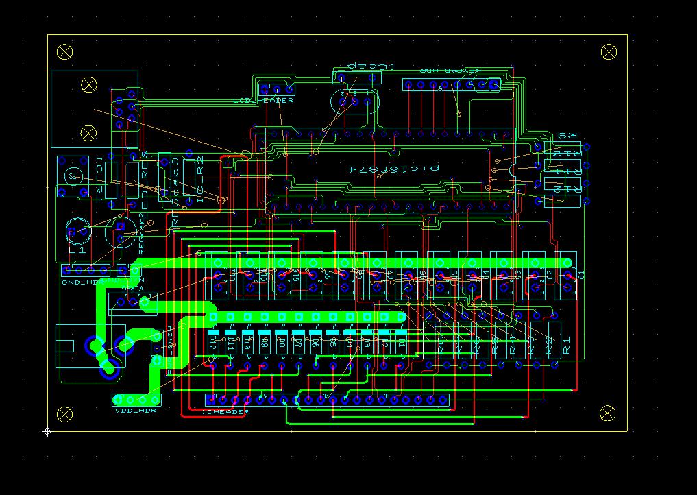
5 Figure 5: amplifier schematic. Once the entire microcontroller circuit was designed in schematic form it had to be transferred to the Ultiboard CAD tool to develop a design for the printed circuit board (PCB). Components from the standard Multisim library contain their physical footprint, which is used by Ultiboard to place the necessary Thru holes. Custom components and footprints can also be defined. The user then places each component footprint in the desired location within Ultiboard. The wire traces are generally routed automatically, although the user can intervene. The trace thickness is calculated with any number of simple online applets ( trace widthcalculator/). This design required the use of separate digital and analog ground networks because the high current sent to ground by the solenoids and motors. The completed Ultiboard CAD drawing is shown in figure 6. The PCB design flies were then sent to a Advanced Circuits for fabrication. Upon receipt of the board the requisite components were soldered into place.
6
ECE 372 Microcontroller Design
 !! "! E.g. Port A, Port B "! Used to interface with many devices!! Switches!! LEDs!! LCD!! Keypads!! Relays!! Stepper Motors "! Interface with digital IO requires us to connect the devices correctly and
Input/Output Ports and Interfacing
 Input/Output Ports and Interfacing ELEC 330 Digital Systems Engineering Dr. Ron Hayne Images Courtesy of Ramesh Gaonkar and Delmar Learning Basic I/O Concepts Peripherals such as LEDs and keypads are essential
Mark Schutzer December 9, 2007 (updated fix for older rev B and C ProCabs)
") Turning on radio ProCabs / PowerCabs Mark Schutzer December 9, 2007 (updated fix for older rev B and C ProCabs) Overview This paper will look into and explain why radio ProCabs / PowerCabs are hard to
Turning on radio ProCabs / PowerCabs Mark Schutzer December 9, 2007 (updated fix for older rev B and C ProCabs) Overview This paper will look into and explain why radio ProCabs / PowerCabs are hard to
Mechatronics and Measurement. Lecturer:Dung-An Wang Lecture 6
 Mechatronics and Measurement Lecturer:Dung-An Wang Lecture 6 Lecture outline Reading:Ch7 of text Today s lecture: Microcontroller 2 7.1 MICROPROCESSORS Hardware solution: consists of a selection of specific
Unit 2. Computer Control. PIC stands for PROGRAMMABLE INTERFACE CONTROLLER. A PIC chip takes in input signals and then controls output transducers
 Unit 2 Computer Control PIC stands for PROGRAMMABLE INTERFACE CONTROLLER A PIC chip takes in input signals and then controls output transducers Name: Form: 2 ASIC or Application Specific Integrated Circuits
Digital I/O Operations
 Digital I/O Operations CSE0420 Embedded Systems By Z. Cihan TAYŞİ Outline Digital I/O Ports, Pins Direction Pull-up & pull-down Arduino programming Digital I/O examples on Arduino 1 Digital I/O Unlike
PIC Dev 14 Through hole PCB Assembly and Test Lab 1
 Name Lab Day Lab Time PIC Dev 14 Through hole PCB Assembly and Test Lab 1 Introduction: The Pic Dev 14 is a simple 8-bit Microchip Pic microcontroller breakout board for learning and experimenting with
Olfaction Satisfaction Week #10 April 5, 2006 Senior Design Team 8
 Olfaction Satisfaction Week #10 April 5, 2006 Senior Design Team 8 Work Completed The first task for Emily this week was to finish debugging the circuit. The sound chip problem was finally figured out.
EMBEDDED SYSTEMS COURSE CURRICULUM
 On a Mission to Transform Talent EMBEDDED SYSTEMS COURSE CURRICULUM Table of Contents Module 1: Basic Electronics and PCB Software Overview (Duration: 1 Week)...2 Module 2: Embedded C Programming (Duration:
Dwarf Boards. DB021 : L298 dual motor driver
 Dwarf Boards DB021 : L298 dual motor driver (c) Van Ooijen Technische Informatica version 1.0 PICmicro, In-Circuit Serial Programming and ICSP are registerd trademarks of Microchip Technology Inc. Introduction
GammaRay USB Module. Beta Innovations DOC No. : Rev. : A2-102 Date : 2, 2004 Part No. : ,
 GammaRay USB Module DOC No. : 16410 Rev. : A2-102 Date : 2, 2004 Part No. : 500-101, 700-100 Beta Innovations (c) 2003 1 Table of Contents Table of Contents...2 GammaRay-64 USB Module...3 GammaRay-256
PCB Design for Capacitance Rain Sensor
 PCB Design for Capacitance Rain Sensor Danny Kang April 14, 2010 EXECUTIVE SUMMARY The definition of sensor is a device that measures a physical quantity and converts it into a signal which can be read
Electromechanical Arithmetic Logic Unit
 Electromechanical Arithmetic Logic Unit Design Report 5/8/2009 David Bober E90: Senior Design Advised by: Prof. Cheever Prof. Moreshet Abstract The Electromechanical Arithmetic Logic Unit (EmALU) implements
Goal: We want to build an autonomous vehicle (robot)
") Goal: We want to build an autonomous vehicle (robot) This means it will have to think for itself, its going to need a brain Our robot s brain will be a tiny computer called a microcontroller Specifically
Goal: We want to build an autonomous vehicle (robot) This means it will have to think for itself, its going to need a brain Our robot s brain will be a tiny computer called a microcontroller Specifically
Explorer V1.20. Features
 V1.20 Multi-function USB I/O Expander and Controller Features Dual h-bridge 1.3A motor drive with PWM speed control 4.6V to 10.8V input range USB communication 4x digital inputs 2x analogue inputs 7x 100mA
Variable Power Supply Digital Control Circuit Diagram Using Lm317
 Variable Power Supply Digital Control Circuit Diagram Using Lm317 DIGITAL POWER SUPPLY USING LM317 A Major Project Report Submitted partial fulfillment of the requirement for the award of the Degree of
PIC Dev 14 Surface Mount PCB Assembly and Test Lab 1
 Name Lab Day Lab Time PIC Dev 14 Surface Mount PCB Assembly and Test Lab 1 Introduction: The Pic Dev 14 SMD is a simple 8-bit Microchip Pic microcontroller breakout board for learning and experimenting
PVK40. User's manual. Feature Rich Development and Educational Kit for 40-pin Microchip PIC microcontrollers
 PVK40 User's manual Feature Rich Development and Educational Kit for 40-pin Microchip PIC microcontrollers CONTENTS PVK40 3 On-board peripherals: 3 Power supply 4 Microcontroller 4 Reset circuitry 4 Oscilator
12v Power Controller Project Board
 12v Power Controller Project Board 12 Volt Power Controller Introduction This board provides three functions... DC power gate Low voltage disconnect Voltage / current display The typical usage for this
PANDORA HACKER GUIDE
 PANDORA HACKER GUIDE WARNING: Modifying your PCB is not covered by your warranty and any damage caused as a result will be the sole responsibility of the owner to fix or to have fixed at a fee set by the
Intro to Multisim & Ultiboard
 Intro to Multisim & Ultiboard (Lab by Wayne Stanton) Note: This document was written for version 13.0 of Multisim and Ultiboard. Note: A grade for this lab will be applied upon receipt of the project file.
Chapter 9. Input/Output (I/O) Ports and Interfacing. Updated: 3/13/12
 Ports and Interfacing. Updated: 3/13/12") Chapter 9 Input/Output (I/O) Ports and Interfacing Updated: 3/13/12 Basic Concepts in I/O Interfacing and PIC18 I/O Ports (1 of 2) I/O devices (or peripherals) such as LEDs and keyboards are essential
Chapter 9 Input/Output (I/O) Ports and Interfacing Updated: 3/13/12 Basic Concepts in I/O Interfacing and PIC18 I/O Ports (1 of 2) I/O devices (or peripherals) such as LEDs and keyboards are essential
Lab 9 Introduction to Multisim & Ultiboard
 Lab 9 Introduction to Multisim & Ultiboard In this lab you will be utilizing your understanding of circuit generation/testing in Multisim in order to create the final project (figure 1), a TinyMatrix pendant.
Problem Score 1 / 27 2 / 19 3 / 16 4 / 14 code check off 5 / 22 /2 Total /100
 ME430 Mechatronics Examination I Page 1 Name CM Section You may use only: ME430 Mechatronics Examination I Sept 22nd, 2016 Problem Score 1 / 27 2 / 19 3 / 16 4 / 14 code check off 5 / 22 /2 Total /100
DEVBOARD3 DATASHEET. 10Mbits Ethernet & SD card Development Board PIC18F67J60 MICROCHIP
 DEVBOARD3 DATASHEET 10Mbits Ethernet & SD card PIC18F67J60 MICROCHIP Version 1.0 - March 2009 DEVBOARD3 Version 1.0 March 2009 Page 1 of 7 The DEVBOARD3 is a proto-typing board used to quickly and easily
TinyTrak4 v7 Hardware Manual
 Overview TinyTrak4 v7 Hardware Manual Version 7.2 July 23, 2017 The TinyTrak4 (TT4) is a radio interface capable of transmitting and receiving position and other digital information over a two-way FM radio.
Introduction to Mechatronics and the Mechatronic Design Center Microchip Technology Incorporated. All Rights Reserved. 1
 Introduction to Mechatronics and the Mechatronic Design Center 2005 Microchip Technology Incorporated. All Rights Reserved. 1 What is Mechatronics? Implementing electronic controls in a mechanical system
ACU6. Technical Reference Manual. Specifications Interfacing Dimensions. Document topics. ANSARI Controller Unit Type 6 technical reference manual
 ACU6 Technical Reference Manual ANSARI Controller Unit Type 6 technical reference manual Document topics Specifications Interfacing Dimensions Document Version: 1.03 13. January 2013 By ANSARI GmbH Friedrich-Ebert-Damm
TLE9869 Eval.Kit V1.0 Users Manual
 TLE9869 Eval.Kit V1.0 Users Manual Contents Abbreviations... 2 1 Concept... 3 2 Interconnects... 4 3 Test Points... 5 4 Jumper Settings... 6 5 Communication Interfaces... 7 5.1 LIN (via Banana jack and
MP6500 Stepper Motor Driver, Digital Current Control
 This breakout board for the MPS MP6500 micro stepping bipolar stepper motor driver is Pololu s latest stepper motor driver. The module has a pinout and interface that are very similar to that of our popular
EasyPIC5 Development System
 EasyPIC5 Development System Part No.: MPMICRO-PIC-Devel- EasyPIC5 Overview EasyPIC5 is a development system that supports over 120 8-, 14-, 18-, 20-, 28- and 40-pin PIC MCUs. EasyPIC5 allows PIC microcontrollers
Lecture 14: Prototyping and Schematics
 Lecture 14: Prototyping and Schematics Breadboards have some limitations They have high parasitic inductance and capacitance, limiting high frequency signal transfer to about 50MHz. Wire connections
HM9708 HM9708. Battery-Powered Equipment Motherboard USB Power Switch USB Device Power Switch Hot-Plug Power Supplies Battery-Charger Circuits DC+ VIN
 200mΩ Power Distribution Switches Features 200mΩ Typ. High-Side MOSFET 0.8A Current Limit (V IN =3.0V) Wide Input Voltage Range: 2V ~ 5.5V Soft Start Thermal Protection Small SOT-23-5 Package Minimizes
Homework 5: Circuit Design and Theory of Operation Due: Friday, February 24, at NOON
 Homework 5: Circuit Design and Theory of Operation Due: Friday, February 24, at NOON Team Code Name: Motion Tracking Laser Platform Group No.: 9 Team Member Completing This Homework: David Kristof NOTE:
Adafruit Powerboost 1000 Basic
 Adafruit Powerboost 1000 Basic Created by lady ada Last updated on 2018-08-22 03:42:57 PM UTC Guide Contents Guide Contents Overview Pinouts Power Pins Control Pins (https://adafru.it/dlz)leds Battery
Introduction to NI Multisim & Ultiboard
 George Washington University School of Engineering and Applied Science Electrical and Computer Engineering Department Introduction to NI Multisim & Ultiboard Dr. Amir Aslani 8/20/2017 2 Outline Design
GammaTron USB Module
 GammaTron USB Module Product ID. : 710 Board Rev. : 1.00 Date : June 24, 2007 Firmware Rev. : 1.11 Beta Innovations (c) 2006 http://www.betainnovations.com Table of Contents Main Features...5 Introduction...6
eace PLC Velocio s Embedded Ace (eace) PLC
 PLC") Velocio s Embedded Ace (eace) PLC eace PLC The eace PLC is a member of the Velocio s groundbreaking series of programmable logic controllers. These PLCs introduce revolutionary new concepts, capabilities,
Velocio s Embedded Ace (eace) PLC eace PLC The eace PLC is a member of the Velocio s groundbreaking series of programmable logic controllers. These PLCs introduce revolutionary new concepts, capabilities,
DEV-1 HamStack Development Board
 Sierra Radio Systems DEV-1 HamStack Development Board Reference Manual Version 1.0 Contents Introduction Hardware Compiler overview Program structure Code examples Sample projects For more information,
Electronic Coin Toss
 1 Electronic Coin Toss Why this circuit? This circuit was not designed for people who can make up their mind nor have a coin to use for a heads or tail coin toss. This circuit can also be used to ask it
Adafruit TB A DC/Stepper Motor Driver Breakout Board
 Adafruit TB6612 1.2A DC/Stepper Motor Driver Breakout Board Created by lady ada Last updated on 2016-10-01 06:35:33 PM UTC Guide Contents Guide Contents Overview Pinouts Power Pins Signal in Pins Motor
TEXAS INSTRUMENTS ANALOG UNIVERSITY PROGRAM DESIGN CONTEST MIXED SIGNAL TEST INTERFACE CHRISTOPHER EDMONDS, DANIEL KEESE, RICHARD PRZYBYLA SCHOOL OF
 TEXASINSTRUMENTSANALOGUNIVERSITYPROGRAMDESIGNCONTEST MIXED SIGNALTESTINTERFACE CHRISTOPHEREDMONDS,DANIELKEESE,RICHARDPRZYBYLA SCHOOLOFELECTRICALENGINEERINGANDCOMPUTERSCIENCE OREGONSTATEUNIVERSITY I. PROJECT
What are output transducers An output transducer will convert electrical signals passed to it by the process into another form of energy.
 What are output transducers An output transducer will convert electrical signals passed to it by the process into another form of energy. ACTIVITY Can you find the symbols of the output components listed
Developement of Multi Interface Board for Educational Trainer Kit
 Journal of Engineering Technology Vol. 2(1): 1-5, 2012 ISSN 2231-8798 2012UniKLBMI Developement of Multi Interface Board for Educational Trainer Kit M.R. Abdullah, Z. Zaharudin, Z. Mahmoodin, Z. Zainuddin
MX Educational Target User Manual
 MX Educational Target User Manual Revision History Date Description Initial release. Table of Contents 1. Introduction... 4 1.1. Module Models... 4 1.2. Package Contents... 4 1.3. Key Hardware Features...
A PIC-based LCD Display for Stand-Alone Instrumentation
 A PIC-based LCD Display for Stand-Alone Instrumentation Michael Case, Dr. Bruce E. Segee Department of Electrical and Computer Engineering University Of Maine Instrumentation Research Laboratory Session
AAZ-0914A USB, Blue tooth and Graphic CPU 50MHZ Antenna Analyzer
 Fox Delta Amateur Radio Projects & Kits FD- AAZ-0914A AAZ-0914A USB, Blue tooth and Graphic CPU 50MHZ Antenna Analyzer AAZ- 0914A KIT: USB Standalone, Blue tooth standalone and Graphic CPU capable 50MHZ*
Homework 6: Printed Circuit Board Layout Design Narrative
 Homework 6: Printed Circuit Board Layout Design Narrative Team Code Name: Treasure Chess Group No. 2 Team Member Completing This Homework: Sidharth Malik E-mail Address of Team Member: malik @ purdue.edu
Study of LED Electronic Writing Screen based on Single Chip Dengjin Wu 1
 4th National Conference on Electrical, Electronics and Computer Engineering (NCEECE 2015) Study of LED Electronic Writing Screen based on Single Chip Dengjin Wu 1 1 North China Electric Power University,
A4988 Stepper Motor Driver Carrier, Black Edition
 A4988 Stepper Motor Driver Carrier, Black Edition A4988 stepper motor driver carrier, Black Edition, bottom view with dimensions. Overview This product is a carrier board or breakout board for Allegro
A4988 Stepper Motor Driver Carrier
 A4988 Stepper Motor Driver Carrier A4983/A4988 stepper motor driver carrier with dimensions. Overview This product is a carrier board or breakout board for Allegro s A4988 DMOS Microstepping Driver with
A4988 Stepper Motor Driver Carrier with Voltage Regulators
 1 of 6 12/2/2011 6:37 PM A4988 Stepper Motor Driver Carrier with Voltage Regulators Pololu item #: 1183 26 in stock Price break Unit price (US$) 1 19.95 10 17.95 100 13.97 Quantity: backorders allowed
MAXREFDES108#: NON-ISOLATED 12V/1A POE POWERED DEVICE POWER SUPPLY
 System Board 6289 MAXREFDES108#: NON-ISOLATED 12V/1A POE POWERED DEVICE POWER SUPPLY To meet the increasing demands for non-isolated Power over Ethernet (PoE) power solutions, Maxim has developed innovative,
MT2 Introduction Embedded Systems. MT2.1 Mechatronic systems
 MT2 Introduction Embedded Systems MT2.1 Mechatronic systems Mechatronics is the synergistic integration of mechanical engineering, with electronics and intelligent computer control in the design and manufacturing
How-To: Make an RGB combination door lock (Part 1)
") How-To: Make an RGB combination door lock (Part 1) Written By: Feitan 2017 www.botsbits.org Page 1 of 14 INTRODUCTION Part 2 can be found here 2017 www.botsbits.org Page 2 of 14 Step 1 How-To: Make an
How-To: Make an RGB combination door lock (Part 1) Written By: Feitan 2017 www.botsbits.org Page 1 of 14 INTRODUCTION Part 2 can be found here 2017 www.botsbits.org Page 2 of 14 Step 1 How-To: Make an
Contents. The USB Logic Tool... 2 Programming... 2 Using the USB Logic Tool... 6 USB Logic Tool Features... 7 Device Hardware...
 USB Logic Tool Contents The USB Logic Tool... 2 Programming... 2 Using the USB Logic Tool... 6 USB Logic Tool Features... 7 Device Hardware... 11 The USB Logic Tool The device is meant to be a prototyping
ELECTRONICS MANUFACTURE-The In-Circuit Test sequence
 ELECTRONICS MANUFACTURE-The In-Circuit Test sequence In-Circuit Test comprises several sections, each consisting of a series of tests on individual devices. By testing devices individually, failures can
LTC4089/-5 DESCRIPTION
 LTC4089/-5 DESCRIPTION Demonstration circuit DC929A-A/B is a monolithic high voltage (6V-36V) switching buck regulator, USB Powerpath controller, and Li-Ion battery charger. It is based on the LTC4089/-5
eip-24/100 Embedded TCP/IP 10/100-BaseT Network Module Features Description Applications
 Embedded TCP/IP 10/100-BaseT Network Module Features 16-bit Microcontroller with Enhanced Flash program memory and static RAM data memory On board 10/100Mbps Ethernet controller, and RJ45 jack for network
Adafruit INA219 Current Sensor Breakout
 Adafruit INA219 Current Sensor Breakout Created by lady ada Last updated on 2018-01-17 05:25:30 PM UTC Guide Contents Guide Contents Overview Why the High Side? How does it work? Assembly Addressing the
UNIVERSITY OF BOLTON SCHOOL OF ENGINEERING B.ENG (HONS) ELECTRICAL AND ELECTRONIC ENGINEERING EXAMINATION SEMESTER /2016
 ELECTRICAL AND ELECTRONIC ENGINEERING EXAMINATION SEMESTER /2016") UNIVERSITY OF BOLTON TW59 SCHOOL OF ENGINEERING B.ENG (HONS) ELECTRICAL AND ELECTRONIC ENGINEERING EXAMINATION SEMESTER 1-2015/2016 INTERMEDIATE EMBEDDED SYSTEMS MODULE NO: EEE5004 Date: Thursday 14 January
UNIVERSITY OF BOLTON TW59 SCHOOL OF ENGINEERING B.ENG (HONS) ELECTRICAL AND ELECTRONIC ENGINEERING EXAMINATION SEMESTER 1-2015/2016 INTERMEDIATE EMBEDDED SYSTEMS MODULE NO: EEE5004 Date: Thursday 14 January
Bolero3M Nexus Emulation Adapter 256BGA 176TQ
 _ V1.4 Adapters Bolero3M Nexus Emulation Adapter 256BGA 176TQ Ordering code IA256BGA176TQ-5646C Supported microcontrollers: Freescale MPC5644B, MPC5644C, MPC5645B, MPC5645C, MPC5646B and MPC5646C ST equivalent
8:1 Serial Port Expander
 8:1 Serial Port Expander V 1.3 This is an evolving document check back for updates. Features Expand a single UART (RX / TX) serial port into 8 additional serial ports On-board LEDs indicate which channel
Good Idea to Working Electronic Model
 Good Idea to Working Electronic Model by Jan H. Lichtenbelt, March 2011 Abstract Seeing an idea manifest itself into a fully working creation is always satisfying, however so many good ideas go to waste
XYLOPHONE KIT ESSENTIAL INFORMATION. Version 2.0 CREATE YOUR OWN ELECTRONIC MUSICAL INTRUMENT WITH THIS
 ESSENTIAL INFORMATION BUILD INSTRUCTIONS CHECKING YOUR PCB & FAULT-FINDING MECHANICAL DETAILS HOW THE KIT WORKS CREATE YOUR OWN ELECTRONIC MUSICAL INTRUMENT WITH THIS XYLOPHONE KIT Version 2.0 Build Instructions
PROGRAMMABLE POWER SUPPLY
 PROGRAMMABLE POWER SUPPLY MATTHIEU L. KIELA HARDWARE DESCRIPTION APRIL 25, 2006 WESTERN WASHINGTON UNIVERSITY ELECTRONICS ENGINEERING TECHNOLOGY ETEC 474, PROFESSOR MORTON INTRODUCTION In laboratory and
I2C-OC805S, I2C-OC805SA I2C Bus 8-Output Open Collectors
 I2C-OC85, I2C-OC85A I2C Bus 8-Output Open Collectors Features PCF8574 and PCF8574A I2C bus I/O expander 8 Outputs Open Collectors Operating voltage 2.5V to 5.5V Inverse polarity protection circuits khz
BSCB-2 BASIC STAMP CARRIER BOARD
 BSCB-2 BASIC STAMP CARRIER BOARD Technical Manual Document Revision: 1.04 Date: 06 August 2003 BiPOM Electronics, Inc. 16301 Blue Ridge Road, Missouri City, Texas 77489 Telephone: 1-713-283-9970 Fax: 1-281-416-2806
MINI DSP EVM KIT Application Manual
 MINI DSP EVM KIT Application Manual Table of contents 1. System overview... 3 2. Features... 3 3. MINI DSP module connections and controls... 4 3.1. External device connections... 5 3.1.1. For GPIO output
SSD1963 EVK Rev3B User s Guide
 SSD1963 EVK Rev3B User s Guide TechToys Company Unit 1807, Pacific Plaza, 410 Des Voeux Road West, Hong Kong Tel: 852-28576267 Fax: 852-28576216 Web site: www.techtoys.com.hk Version 1.0a Page 1 Table
SHARP PC-1600 Custom Barcode Reader
 SHARP PC-1600 Custom Barcode Reader by Tom Stahl This hack is about building a custom CE-1601N substitute including driver software for the SHARP PC-1600. Hardware Datalogic P51 dumb wand (reader pen)
None. MICROCONTROLLERS III
 MICROCONTROLLERS III PREREQUISITES: MODULE 10: MICROCONTROLLERS II. OUTLINE OF MODULE 11: What you will learn about in this Module: Use of a much more powerful microcontroller: the PIC16F877 In-circuit
solutions for teaching and learning
 RKP18Motor Component List and Instructions PCB layout Constructed PCB Schematic Diagram RKP18Motor Project PCB Page 1 Description The RKP18Motor project PCB has been designed to use PIC microcontrollers
Adafruit Powerboost 1000C
 Adafruit Powerboost 1000C Created by lady ada Last updated on 2017-03-10 08:56:30 PM UTC Guide Contents Guide Contents Overview Pinouts Power Pins Control Pins LEDs Battery and USB connection Assembly
04/12/11 version 1.0
 04/12/11 version 1.0 Assembly Manual and Hardware Description for the Universal Graphics Display Module Kit This document describes the physical assembly and operation of the new KibaCorp Universal Graphic
This presentation will..
 Component Identification: Digital Introduction to Logic Gates and Integrated Circuits Digital Electronics 2014 This presentation will.. Introduce transistors, logic gates, integrated circuits (ICs), and
Mega128-DEVelopment Board Progressive Resources LLC 4105 Vincennes Road Indianapolis, IN (317) (317) FAX
 (317) FAX") Mega128-DEVelopment Board Progressive Resources LLC 4105 Vincennes Road Indianapolis, IN 46268 (317) 471-1577 (317) 471-1580 FAX http://www.prllc.com GENERAL The Mega128-Development board is designed for
Mega128-DEVelopment Board Progressive Resources LLC 4105 Vincennes Road Indianapolis, IN 46268 (317) 471-1577 (317) 471-1580 FAX http://www.prllc.com GENERAL The Mega128-Development board is designed for
Laboratory 10. Programming a PIC Microcontroller - Part II
 Laboratory 10 Programming a PIC Microcontroller - Part II Required Components: 1 PIC16F88 18P-DIP microcontroller 1 0.1 F capacitor 3 SPST microswitches or NO buttons 4 1k resistors 1 MAN 6910 or LTD-482EC
Eddie Control Board with Power Connector (#28993) Eddie Control Board PCB (# )
 Eddie Control Board PCB (# )") Web Site: www.parallax.com Forums: forums.parallax.com Sales: sales@parallax.com Technical: support@parallax.com Office: (916) 624-8333 Fax: (916) 624-8003 Sales: (888) 512-1024 Tech Support: (888) 997-8267
Web Site: www.parallax.com Forums: forums.parallax.com Sales: sales@parallax.com Technical: support@parallax.com Office: (916) 624-8333 Fax: (916) 624-8003 Sales: (888) 512-1024 Tech Support: (888) 997-8267
Bachelor of Engineering in Computer and Electronic Engineering
 Bachelor of Engineering in Computer and Electronic Engineering Computer Engineering 1 Year 2 Semester 3 Autumn 08 Niall O Keeffe Instructions to Candidates: - 2 hours duration Answer 4 out of 6 questions.
ARDUINO MINI 05 Code: A000087
 ARDUINO MINI 05 Code: A000087 The Arduino Mini is a very compact version of the Arduino Nano without an on board USB to Serial connection The Arduino Mini 05 is a small microcontroller board originally
Thursday, September 15, electronic components
 electronic components a desktop computer relatively complex inside: screen (CRT) disk drive backup battery power supply connectors for: keyboard printer n more! Thursday, September 15, 2011 integrated
Finite State Machine Lab
 Finite State Machine Module: Lab Procedures Goal: The goal of this experiment is to reinforce state machine concepts by having students design and implement a state machine using simple chips and a protoboard.
Basic Interface Techniques for the CRD155B
 Basic Interface Techniques for the CRD155B April 2001, ver. 1.10 Application Note 101 Introduction This application note contains basic information about interfacing external circuitry to computer I/O
Bill of Materials: 8x8 LED Matrix Driver Game PART NO
 8x8 LED Matrix Driver Game PART NO. 2171031 This Game Maker II kit is a game design platform using a single color 8x8 matrix LED without the need for a shift register or expensive Arduino. The kit includes
DEV16T. LCD Daughter board
 LCD Daughter board Table of Contents 1 Introduction...2 2 Features...3 3 Expansion Connectors...4 3.1 Daughter Board Connectors...4 4 LCD Display...5 5 Input Buttons S1 to S4...5 6 Buzzer...5 7 Connector
Parallel I/O and Keyboard Scanning
 4 4.1 Objectives: Microprocessors can monitor the outside world using input ports. They can also control it using output ports. The TM4C123G (Tiva) performs I/O using 6 ports. Computer keyboards are typically
ATLD10A5-D EV1.0 Evaluation Board for ATLD10A5-D 10A High Efficiency Laser Controller ATLD10A5-D Evaluation Board Rev. 1.0
 ATLD0A5-D EV.0 Evaluation Board for ATLD0A5-D 0A High Efficiency Laser Controller ATLD0A5-D Evaluation Board Rev..0 Figure ATLD0A5-D EV.0 Photo INTORDUCTION The ATLD0A5-D is an electronic module designed
RKP08 Component List and Instructions
 RKP08 Component List and Instructions PCB layout Constructed PCB RKP08 Scematic RKP08 Project PCB Page 1 Description The RKP08 project PCB has been designed to use PIC microcontrollers such as the Genie
Adafruit PowerBoost Charger
 Adafruit PowerBoost 500 + Charger Created by lady ada Last updated on 2015-10-21 12:44:24 PM EDT Guide Contents Guide Contents Overview Pinouts Power Pins Control Pins LEDs Battery and USB connection On/Off
Device: FDRV-04S. This document version: v1. Matches module version: v2 [2 Oct 2015] Document revision date: 9 November 2015
![Device: FDRV-04S. This document version: v1. Matches module version: v2 [2 Oct 2015] Document revision date: 9 November 2015](/thumbs/93/113411552.jpg "Device: FDRV-04S. This document version: v1. Matches module version: v2 [2 Oct 2015] Document revision date: 9 November 2015") Device: FDRV-04S This document version: v1 Matches module version: v2 [2 Oct 2015] Document revision date: 9 November 2015 Description: I2C 4 Device Motor / Solenoid Driver Board FDRV-04S HWv2 datasheet
Device: FDRV-04S This document version: v1 Matches module version: v2 [2 Oct 2015] Document revision date: 9 November 2015 Description: I2C 4 Device Motor / Solenoid Driver Board FDRV-04S HWv2 datasheet
Design And Simulation Of Power Factor Measurement Circuit By Using Pic
 Design And Simulation Of Power Factor Measurement Circuit By Using Pic The most common power factor measurement circuits involve zero crossing In (6) a power factor measurement circuit for AC motors was
MIDI CPU Hardware Rev K. User Manual
 MIDI CPU Hardware Revision K User Manual Updated 2010-09-08 Additional documentation available at: http://highlyliquid.com/support/ Page 1 / 18 Table of Contents 1.0 Important Safety Information...2 2.0
Adafruit PowerBoost Charger
 Adafruit PowerBoost 500 + Charger Created by lady ada Last updated on 2017-06-01 04:08:36 PM UTC Guide Contents Guide Contents Overview Pinouts Power Pins Control Pins LEDs Battery and USB connection On/Off
Rapid40i PIC Prototyping PCB User Manual
 Description This is a PCB designed to facilitate the rapid prototyping of a device based on a 40 pin Microchip PIC microcontroller. To allow users to focus on their application, we take care of key housekeeping
Bolero Nexus Emulation Adapter 208BGA 100TQ
 _ V1.5 Adapters Bolero Nexus Emulation Adapter 208BGA 100TQ Ordering code IA208BGA100TQ-5607B Supported microcontrollers: Freescale MPC5605B, MPC5605BK, MPC5606BK ST equivalent devices (SPC560B54, SPC560B60)
eip-10 Embedded TCP/IP 10-BaseT Network Module Features Description Applications
 Embedded TCP/IP 10-BaseT Network Module Features 8-bit reprogrammable Microcontroller with Enhanced Flash program memory, EEPROM and Static RAM data memory On board 10Mbps Ethernet controller, and RJ45
UNIVERSITY OF BOLTON SCHOOL OF ENGINEERING MSC SYSTEMS ENGINEERING AND ENGINEERING MANAGEMENT SEMESTER 2 EXAMINATION 2016/2017
 TW30 UNIVERSITY OF BOLTON SCHOOL OF ENGINEERING MSC SYSTEMS ENGINEERING AND ENGINEERING MANAGEMENT SEMESTER 2 EXAMINATION 2016/2017 MICROPROCESSOR BASED SYSTEMS MODULE NO: EEM7016 Date: Wednesday 17 May
Silicon Steroids for the Stamp Help Your Projects Heft Big Loads Using Switching Transistors
 Column #6, August 1995 by Scott Edwards: Silicon Steroids for the Stamp Help Your Projects Heft Big Loads Using Switching Transistors ONE of the outstanding characteristics of the PIC microcontroller used
AL3159 Evaluation Module
 Device Features Description V IN Range: 2.7V to 5.5V Up to 93% Max Power Efficiency 1% Current Matching Accuracy Between Channels Three Simple Logic Decoding LED On/Off Control Inputs Low Transition Threshold