USER GUIDE ARDBOX ANALOG
|
|
|
- Owen Logan
- 5 years ago
- Views:
Transcription
1 USER GUIDE ARDBOX ANALOG Version: _Ardbox_Analog
2 Page2 Ardbox User Guide: 1 Contents 2 ARDBOX Precautions Arduino Board Intended Audience General Precautions Technical Specifications General Specifications: Performance Specification: Software interface How to connect PLC Arduino to PC How to connect PLC to power supply Ardbox Analog I/O Pinout:... 9 Zone Connections Switch configuration I/0 technical details Connector details ARDBOX Family Dimensions: DIN rail mounting:... 17
 Polarity protection Max.")

3 Page3 2 ARDBOX A compact PLC based in Open Source Hardware technology. With different Input/Outputs Units. COMPACT PLC ARDUINO 1224Vdc ARDBOX ANALOG Alimentation Voltage 1224Vdc Fuse protection (1A) Polarity protection Max. current consumption 0,5A Size Clock Speed Flash Memory SRAM 100x45x115 16MHz 32KB of which 4KB are used by bootlader 2.5KB EEPROM 1KB I2C Communications USB RS232 RS485 SPI TOTAL Input points 10 TOTAL Output points 10 INPUTS Digital range:12/24 Vdc (7.6 to 25.4 Vdc) Analog range: 010 Vdc Digital 10 12/24Vdc I min: 3/6 ma Separated PCB ground Analog 10 bits 9 of 10 Digital input 010V Input Impedance: 39K Separated PCB ground * Interrupt HS 1 of 10 Digital input 12/24Vdc I min: 5/10 ma Separated PCB ground *The same input is not simultaneously compatible as InterrupHS and Digital. IMPORTANT 1 Pullup resistance required for i2c (IS.ACI2C4.7K)


4 Page4 OUTPUTS Digital Isolated range: 5/12/24 Vdc (4.6 to 25.4 Vdc) Analog range: 010 Vdc Digital Isolated 10 5/12/24 Vdc I max: 0.3 A Galvanic INSULATION Diode Protected for Relay Analog 8 bits Vdc I max: 40 ma Separated PCB ground PWM Isolated 8bit 6 of 10 Digital isolated Output 5/12/24 Vdc I max: 0.3 A Galvanic INSULATION Diode Protected for Relay Expandability I2C 1 RS232 RS485 SPI Reference IS.AB20AN.base 3 Precautions Read this manual before attempting to use the Ardbox and follow its descriptions for reference during operation 1.1. Arduino Board All Ardbox family PLCs include Arduino LEONARDO Board as controller Intended Audience This manual is intended for technicians, which must have knowledge on electrical systems General Precautions The user must operate Ardbox according to the performance specifications described in this manual. Before using Ardbox under different conditions from the what is specified in this manual or integrating Ardbox to nuclear control systems, railroad systems, aviation systems, vehicles, combustion systems, medical equipment, amusement machines, safety equipment and other systems, machines, and equipment that may have a serious influence on lives and property if used improperly, consult your INDUSTRIAL SHIELDS representative. Ensure that the rating and performance characteristics of Ardbox are sufficient for the systems, machines, and
5 Page5 equipment, and be sure to provide the systems, machines, and equipment double safety mechanisms. This manual provides information for programming and operating the Ardbox. Warnings: Unused pins should not be connected. Ignoring the directive may damage the controller. Improper use of this product may severely damage the controller. Refer to the controller s User Guide regarding wiring considerations. Before using this product, it is the responsibility of the user to read the product s User Guide and all accompanying documentation. 4 Technical Specifications 4.1 General Specifications: Power supply voltage DC power supply 12/24Vdc Operating voltage range DC power supply 11.4 to 25.4Vdc Power consumption DC power supply 30VAC max. External power supply Power supply voltage Power supply output capacity 12/24Vdc 700Ma Insulation resistance Dielectric strength Shock resistance 20MΩ min.at 500Vdc between the AC terminals and the protective earth terminal VAC at 50/60 HZ for one minute with a leakage current of 10mA max. Between all the external AC terminals and the protective earth terminal. 80m/s2 in the X, Y and Z direction 2 times each. Ambient temperature (operating) 0º to 45ºC Ambient humidity (operating) 10% to 90% (no condensation) Ambient environment (operating) With no corrosive gas Ambient temperature (storage) 20º to 60ºC Power supply holding time 2ms min. Weight 340g max.
 EEPROM Clock Speed ARDUINO LEONARDO Stored")
6 Page6 4.2 Performance Specification: Arduino Board Control method I/O control method Programming language Microcontroller Flash Memory Program capacity (SRAM) EEPROM Clock Speed ARDUINO LEONARDO Stored program method Combination of the cyclic scan and immediate refresh processing methods. Arduino IDE. Based on wiring (Wiring is an Open Source electronics platform composed of a programming language. similar to the C. ATmega32u4 32kb of which 4 kb are used by bootloader 2.5kb 1kb 16MHz 5 Software interface Industrial Shields programming environment is Arduino IDE. You can download start code for Ardbox Relay at section 20 IOs PLCs /Ardbox Relay / Document files.


7 Page7 6 How to connect PLC Arduino to PC Connect USB cable from PLC to PC. NOTE: Ardbox Family use micro USB cable. Open Arduino IDE interface: Available at: Select Arduino Board NOTE: Ardbox integrates Arduino Leonardo as controller board. Select correct port. IMPORTANT: Verify the USB port is detected:


8 Page8 7 How to connect PLC to power supply Ardbox Family PLCs are 1224Vdc supplied. IMPORTANT: The polarity IS NOT REVERSAL! Make sure that the live and GND connector of the power supply match the PLC. Make sure that the power supply mains output is not higher than 24Vdc. Suggested power suppliers * Not recommended for industrial applications. The Jack connector needs to be removed and use the live and GND connectors.
9 Page9 Ardbox Connector Arduino Pin Function Ardbox Connector Arduino Pin Function 8 Ardbox Analog I/O Pinout: Zone Connections Base (common unit) RIGHT Zone RIGHT Zone A0.6 A0.5 A0.4 A0.3 A0.2 A0.1 A0.0 Q Analog Out Analog Out Analog Out Analog Out Analog Out Analog Out Analog Out Digital Output Switch config* (see section 9 for Analog/Digital Outputs configuration) Analog Outputs pinout Q0.8 1 Digital Output Q0.7 7 Digital Output Q0.6 Q0.5 Q0.4 Q0.3 Q0.2 Q0.1 Q0.0 GNDCOM 24VCOM PWM/digital Output PWM/digital Output PWM/digital Output PWM/digital Output PWM/digital Output PWM/digital Output PWM/digital Output Isolated GND Isolated VIN Digital/PWM Output pinout Isolated VIN/GND for Outputs Power supply connectors (24Vdc Gnd) Base (common unit) LEFT Zone LEFT Zone RE DE SCL SDA TX RX A B GND 5V RESET SCK MOSI MISO I0.9 I0.8 I0.7 I0.6 I0.5 I0.4 I0.3 I0.2 I0.1 I A0 A1 A2 A3 A4 A RS485/SPI(SS) RS485/SPI(SS) I2C/SPI(SS) I2C/SPI(SS) RS232 RS232 RS485 RS485 GND 5V OUT RESET SPI SPI SPI Analog/Digital Input Analog/Digital Input Analog/Digital Input Analog/Digital Input Analog/Digital Input Analog/Digital Input Analog/Digital Input Analog/Digital Input Analog/Digital Input Digital interrupt Switch config* (see section 9 for Switch configuration. Enabling Communications disables some I/Os) Communications pinout (SPI, I2C, RS485, RS232) Inputs pinout
10 Page10 Config switch * (see section 9 for communications configuration) Input / Output LED Power LED Arduino Reset button
11 Page11 9 Switch configuration General Switches Configurations TOP ZONE ENABLED CONNECTION ON OFF Q0.1 Q0.1 RO RO RO Q0.1 Q0.2 Q0.2 DI DI DI Q0.2 LEFT ZONE SWITCH CONFIGURATION ARDUINO PIN OFF* ON 7 DE Q0.7 4 RE I0.3 1 Q0.8 RX 0 Q0.9 TX 2 SDA I0.0 3 SCL Q0.6 *IMPORTANT: LEFT ZONE. To enable communication connections the switchs must be set to OFF. Set to ON position to enable I/Os PLC connection. Communications and I/Os on the chart can not work simultaneously. For exemple if DE is enabled (OFF), Q0.7 will not work. OFF position provides direct connection to Arduino Pin (NOT for TX and RX), so they can be programmed according to Arduino pin features. TOP ZONE. Communications and outputs can not work simultaneously. If Q0.1 is enabled RO must be disabled and conversely. RS 485 Switch configuration RS485 CONFIGURATION TOP ZONE LEFT ZONE Q0.1 OFF DE OFF RO ON RE OFF Q0.2 OFF RX (ON/OFF) DI ON TX (ON/OFF) SDA SCL (ON/OFF) (ON/OFF) RS485: Enable RE/DE/DI and RO internal pins with configuration switches. I0.3, Q0.1, Q0.2 and Q0.7 not available. The defined Arduino Mega pins for RS485 are showed in the chart below.
12 Page12 RS232 Switch configuration RS232 CONFIGURATION TOP ZONE LEFT ZONE Q0.1 (ON/OFF) DE (ON/OFF) RO (ON/OFF) RE (ON/OFF) Q0.2 (ON/OFF) RX ON DI (ON/OFF) TX ON SDA (ON/OFF) SCL (ON/OFF) RS232: Enable RX and TX connections with configuration switches. Q0.8 and Q0.9 not available I2C Switch configuration i2c CONFIGURATION TOP ZONE LEFT ZONE Q0.1 (ON/OFF) DE (ON/OFF) RO (ON/OFF) RE (ON/OFF) Q0.2 (ON/OFF) RX (ON/OFF) DI (ON/OFF) TX (ON/OFF) (ON/OFF) SDA SCL OFF OFF I2C: Enable SCL and SDA connections (direct Arduino pins) with configuration switches. I0.0 and Q0.6 not available. In order to implement this communication a 4.7kΩ pullup resistor (IS.ACI2C4.7K) is required. Analog/Digital Output Switch Configuration RIGHT SIDE SWITCH CONFIG Output ON OFF NC NC NC Q0.6 DIGITAL A0.6 Q0.5 DIGITAL A0.5 Q0.4 DIGITAL A0.4 Q0.3 DIGITAL A0.3 Q0.2 DIGITAL A0.2 Q0.1 DIGITAL A0.1 Q0.0 DIGITAL A0.0


13 Page13 10 I/0 technical details Digital Output Waveform Digital Output Turnoff PWM Waveform


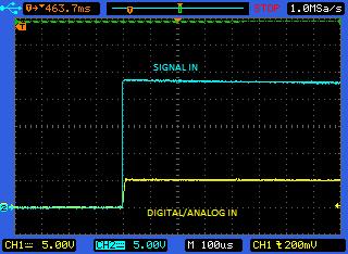
14 Page14 Analog Out Turnon Analog Out Turnoff Analog/Digital Input Turnon

15 Page15 Analog/Digital Input Turnoff 11 Connector details The connector inside the PLCs that mounts on the PCB is MC 0,5/10G2,5 THT from Phoenix contact. MC0,5/10G2,5THT For I/O and power supply there is a FKMC 0,5/10ST2, connector from Phoenix contact. FKMC 0,5/10ST2,5 Connection details: Article reference Height MC 0,5/10G2,5 THT 8,1mm Pitch 2,5mm Dimension 22,5mm Pin dimensions 0,8x0,8mm Pin spacing 2,50mm

16 Page16 Article reference Rigid conduit section min. FKMC 0,5/10ST2,5 0,14 mm² Rigid conduit section max. 0,5 mm² Flexible conduit section min. 0,14 mm² Flexible conduit section max. 0,5 mm² Conduit section AWG/kcmil min. 26 Conduit section AWG/kcmil max. 20


17 Page17 12 ARDBOX Family Dimensions: 13 DIN rail mounting: 45mm width
18 Page18 About Industrial Shields: SPAIN Divina Pastora 1315 Baixos Manresa (Barcelona) Tel Mail: industrialshields@industrialshields.com
USER GUIDE ARDBOX ANALOG HF. Version: IS_AB20ANA.7.1
 USER GUIDE ARDBOX ANALOG HF Version: IS_AB20ANA.7.1 Ardbox User Guide: Contents ARDBOX... 3 Precautions... 4 Arduino Board... 4 Intended Audience... 4 General Precautions... 4 Technical Specifications...
USER GUIDE ARDBOX ANALOG
 USER GUIDE ARDBOX ANALOG Version: 150715_Ardbox_Analog Page2 Ardbox User Guide: 1 Contents 2 ARDBOX FAMILY GUIDE... 3 3 Precautions... 4 1.1. Arduino Board... 4 1.2. Intended Audience... 4 1.3. General
USER GUIDE ARDBOX RELAY
 USER GUIDE ARDBOX RELAY Version: 150715_Ardbox_Relay Page2 Ardbox User Guide: 1 Contents 2 ARDBOX FAMILY GUIDE... 3 3 Precautions... 4 3.1 Arduino Board... 4 3.2 Intended Audience... 4 3.3 General Precautions...
M-DUINO FAMILY. M-Duino 21 User Guide: 1 Index
 Page1 MDUINO FAMILY MDuino 21 User Guide: 1 Index 2 General Description MDUINO FAMILY product... 3 2.1 Mechanical dimension... 4 3 Precautions... 5 3.1 Arduino Board... 5 3.2 Intended Audience... 5 3.3
M-DUINO R FAMILY. M-Duino 19R/38R/57R User Guide: 1 Index
 Page1 M-DUINO R FAMILY M-Duino 19R/38R/57R User Guide: 1 Index 2 General Description M-DUINO R FAMILY product... 3 2.1 Mechanical dimension... 4 3 Precautions... 5 3.1 Arduino Board... 5 3.2 Intended Audience...
USER GUIDE PLC Arduino ARDBOX 20 I/Os Analog HF Modbus
 USER GUIDE PLC Arduino ARDBOX 20 I/Os Analog HF Modbus Cat. Nº: ABOX-103-001-71 Page2 PLC Arduino ARDBOX 20 I/Os Relay HF User Guide Revised March 2018 This user guide is for version PLC Arduino ARDBOX
USER GUIDE. PLC Arduino ARDBOX 20 I/Os Relay HF. Cat. Nº: ABOX
 USER GUIDE PLC Arduino ARDBOX 20 I/Os Relay HF Page2 PLC Arduino ARDBOX 20 I/Os Relay HF User Guide Revised March 2018 This user guide is for version PLC Arduino ARDBOX 20 I/Os Relay HF, with Reference
M-DUINO FAMILY. M-Duino Family User Guide: Ref. IS.MDUINO.XXX
 MDUINO FAMILY MDuino Family User Guide: Ethernet PLC User Guide Revised March 2018 Preface This User Guide is been implemented by Boot & Work, S.L. working under the name Industrial Shields. Purpose of
M-DUINO PLUS FAMILY. M-Duino PLUS Family User Guide: Ref. IS.MDUINO.XXX
 MDUINO PLUS FAMILY MDuino PLUS Family User Guide: Ethernet PLC User Guide Revised March 2018 Preface This User Guide is been implemented by Boot & Work, S.L. working under the name Industrial Shields.
ARDBOX FAMILY USER GUIDE
 ARDBOX FAMILY USER GUIDE Page2 Ardbox User Guide: Contents ARDBOX FAMILY GUIDE... 3 ARDBOX PNP GUIDE... 4 ARDBOX TCH GUIDE... 6 ARDBOX ANALOG GUIDE... 8 ARDBOX RELAY GUIDE... 10 Software Interface:...
Products Datasheet. The economic automation products. ü Fast programming with internet community
 Products Datasheet Safety in industrial applications: new industrial equipment by Industrial Shields provides economical solutions for industrial applications that require flexibility, safety and high
ARDUINO LEONARDO WITH HEADERS Code: A000057
 ARDUINO LEONARDO WITH HEADERS Code: A000057 Similar to an Arduino UNO, can be recognized by computer as a mouse or keyboard. The Arduino Leonardo is a microcontroller board based on the ATmega32u4 (datasheet).
ARDUINO MICRO WITHOUT HEADERS Code: A000093
 ARDUINO MICRO WITHOUT HEADERS Code: A000093 Arduino Micro is the smallest board of the family, easy to integrate it in everyday objects to make them interactive. The Micro is based on the ATmega32U4 microcontroller
Sanguino TSB. Introduction: Features:
 Sanguino TSB Introduction: Atmega644 is being used as CNC machine driver for a while. In 2012, Kristian Sloth Lauszus from Denmark developed a hardware add-on of Atmega644 for the popular Arduino IDE and
ARDUINO LEONARDO ETH Code: A000022
 ARDUINO LEONARDO ETH Code: A000022 All the fun of a Leonardo, plus an Ethernet port to extend your project to the IoT world. You can control sensors and actuators via the internet as a client or server.
ARDUINO MEGA 2560 REV3 Code: A000067
 ARDUINO MEGA 2560 REV3 Code: A000067 The MEGA 2560 is designed for more complex projects. With 54 digital I/O pins, 16 analog inputs and a larger space for your sketch it is the recommended board for 3D
Arduino Uno. Arduino Uno R3 Front. Arduino Uno R2 Front
 Arduino Uno Arduino Uno R3 Front Arduino Uno R2 Front Arduino Uno SMD Arduino Uno R3 Back Arduino Uno Front Arduino Uno Back Overview The Arduino Uno is a microcontroller board based on the ATmega328 (datasheet).
7. Approved Standards US: UL, CSA UL: FILE No.E CSA: FILE No.LR31928) 8. Special Function None : Standard U : For ultrasonically cleanable
 8. Special Function None : Standard U : For ultrasonically cleanable") Subminiature, Sensitive SPDT Signal Switching Relay High sensitivity: 98-mW (Rated power consumption: mw) pickup coil power. Impulse withstand of 1,V ( 1 μs) meets FCC requirements. Stick packing employed
Subminiature, Sensitive SPDT Signal Switching Relay High sensitivity: 98-mW (Rated power consumption: mw) pickup coil power. Impulse withstand of 1,V ( 1 μs) meets FCC requirements. Stick packing employed
ARDUINO MEGA ADK REV3 Code: A000069
 ARDUINO MEGA ADK REV3 Code: A000069 OVERVIEW The Arduino MEGA ADK is a microcontroller board based on the ATmega2560. It has a USB host interface to connect with Android based phones, based on the MAX3421e
keyestudio Keyestudio MEGA 2560 R3 Board
 Keyestudio MEGA 2560 R3 Board Introduction: Keyestudio Mega 2560 R3 is a microcontroller board based on the ATMEGA2560-16AU, fully compatible with ARDUINO MEGA 2560 REV3. It has 54 digital input/output
ESPino - Specifications
 ESPino - Specifications Summary Microcontroller ESP8266 (32-bit RISC) WiFi 802.11 (station, access point, P2P) Operating Voltage 3.3V Input Voltage 4.4-15V Digital I/O Pins 9 Analog Input Pins 1 (10-bit
ARDUINO UNO REV3 SMD Code: A The board everybody gets started with, based on the ATmega328 (SMD).
.") ARDUINO UNO REV3 SMD Code: A000073 The board everybody gets started with, based on the ATmega328 (SMD). The Arduino Uno SMD R3 is a microcontroller board based on the ATmega328. It has 14 digital input/output
ARDUINO UNO REV3 SMD Code: A000073 The board everybody gets started with, based on the ATmega328 (SMD). The Arduino Uno SMD R3 is a microcontroller board based on the ATmega328. It has 14 digital input/output
Arduino ADK Rev.3 Board A000069
 Arduino ADK Rev.3 Board A000069 Overview The Arduino ADK is a microcontroller board based on the ATmega2560 (datasheet). It has a USB host interface to connect with Android based phones, based on the MAX3421e
ARDUINO UNO REV3 Code: A000066
 ARDUINO UNO REV3 Code: A000066 The UNO is the best board to get started with electronics and coding. If this is your first experience tinkering with the platform, the UNO is the most robust board you can
Process displays For current and voltage
 Features Voltage input TRMS-AC/DC up to 600 V Current input AC/DC 1 A, 5 A and shunt (precision resistor) 60 or 100 mv With 2 or 4 limits Display range can be linearised Min, Max, Hold functions 4 20 ma
EC07 EC63. Compatible actuators: ERL2 ESD2. How to order EC 07 B. Series. B Installation. method
 Controller EC07 EC63 Compatible actuators: ERL ESD Features Compact, light weight and thin (Body width 35mm) Can be set without manual Perfect installation compatibility with actuator PC software available
ARDUINO YÚN MINI Code: A000108
 ARDUINO YÚN MINI Code: A000108 The Arduino Yún Mini is a compact version of the Arduino YUN OVERVIEW: Arduino Yún Mini is a breadboard PCB developed with ATmega 32u4 MCU and QCA MIPS 24K SoC CPU operating
XH2. Half-pitch Board-to-Board Connectors
 Half-pitch Board-to-Board Connectors XH2 Allows High-density Mounting for Electronic Devices. A Half-Pitch Connector with a 1.27-mm Pitch for Compactness. A pitch of 1.27 mm for high-density mounting of
SS Series Compatible Mounting with a Simple Construction and Easy-to-Use Design Concept
 Subminiature Basic Switch SS Series Compatible Mounting with a Simple Construction and Easy-to-Use Design Concept One-piece terminal construction to keep out flux. A single leaf movable spring construction.
Despite its ultra-slim design, a CPM2C system can provide up to 192 I/O points!
 Despite its ultra-slim design, a CPM2C system can provide up to 192 I/O! Model Numbers Expansion I/O Units Name CPM1A-8ET 8 input Transistor outputs (sinking) CPM1A-8ED 8 DC inputs CPM1A-8ER 8 relay outputs
BMX DDM Mixed Relay Input/Output module
 Modicon M340 Using Unity Pro BMX DDM 16025 35012474 07/2012 BMX DDM 16025 Mixed Relay Input/Output module 22 Subject of this Section This section presents the BMX DDM 16025 module, its characteristics,
XC7. DIN Sequence Connectors. An improved DIN-standard Sequence. Connectors. connectors. Ratings and Characteristics. Materials and Finish
 DIN Sequence Connectors XC7 An improved DIN-standard Sequence Connector ows power line to daughter board connection first and removal last. Used the same way as regular DIN connectors. Dimensions are those
5. Terminal Shape P: PCB Terminals 6. Classification None : Standard ST : Stand-off 0.64 mm 15 : High-sensitivity (150 mw) Low-sensitivity
 Low-sensitivity") World's tandard Model! Resistant to electromagnetic interference, enables high-density mounting. Impulse withstand voltage of 1,5V meets FCC requirements. old-clad twin-contacts provide short contact bounce
World's tandard Model! Resistant to electromagnetic interference, enables high-density mounting. Impulse withstand voltage of 1,5V meets FCC requirements. old-clad twin-contacts provide short contact bounce
XC5. DIN-style Twin-contact Connectors. Expanding the DIN Concept. Materials and Finish. Ratings and Characteristics
 DIN-style Twin-contact Connectors Expanding the DIN Concept Mates with DIN connectors. Ideal for automated soldering because the Connectors sit on top of the board. Mounting dimensions of the DIN Style-1
ARDUINO YÚN Code: A000008
 ARDUINO YÚN Code: A000008 Arduino YÚN is the perfect board to use when designing connected devices and, more in general, Internet of Things projects. It combines the power of Linux with the ease of use
G9SA. Safety Relay Unit. The G9SA Series Offers a Complete Line-up of Compact Units. Model Number Structure
 Safety Relay Unit G9 CSM_G9_DS_E The G9 Series Offers a Complete Line-up of Compact Units. Four kinds of -mm wide Units are available: A -pole model, a -pole model, and models with poles and OFF-delay
ARDUINO M0 PRO Code: A000111
 ARDUINO M0 PRO Code: A000111 The Arduino M0 Pro is an Arduino M0 with a step by step debugger With the new Arduino M0 Pro board, the more creative individual will have the potential to create one s most
IDUINO for maker s life. User Manual. For IDUINO Mega2560 Board(ST1026)
") User Manual For IDUINO Mega2560 Board(ST1026) 1.Overview 1.1 what is Arduino? Arduino is an open-source prototyping platform based on easy-to-use hardware and software. Arduino boards are able to read
User Manual For IDUINO Mega2560 Board(ST1026) 1.Overview 1.1 what is Arduino? Arduino is an open-source prototyping platform based on easy-to-use hardware and software. Arduino boards are able to read
CPU Units with 20 I/O points
 CPM2A General s CPU Units with 20 I/O points CPU Units with 30 I/O points CPU Units with 40 I/O points Supply voltage AC power 100 to 240 VAC, 50/60 Hz DC power 24 VDC Operating voltage AC power 85 to
IDUINO for maker s life. User Manual. For IDUINO development Board.
 User Manual For IDUINO development Board 1.Overview 1.1 what is Arduino? Arduino is an open-source prototyping platform based on easy-to-use hardware and software. Arduino boards are able to read inputs
FEATURES DESCRIPTION FEATURES
 FEATURES Two High Speed Counters Two Pulse Train Outputs Two Pulse Width Modulation Outputs 24 Sinking or Sourcing Inputs 16 Outputs 1 RS232 Port 2 RS485 Ports Supports Modbus RTU Protocol Communicate
ARDUINO MINI 05 Code: A000087
 ARDUINO MINI 05 Code: A000087 The Arduino Mini is a very compact version of the Arduino Nano without an on board USB to Serial connection The Arduino Mini 05 is a small microcontroller board originally
E2K-F. Flat Capacitive Sensor with a Thickness of Only 10 mm. Flat Proximity Sensor. Ordering Information. Sensors [Refer to Dimensions on page 4.
 Flat Proximity Sensor EK-F CSM_EK-F_DS_E Flat Capacitive Sensor with a Thickness of Only mm Flat Sensor with excellent space efficiency. (Model with built-in Amplifier is only mm thick.) Direct mounting
E2EZ-X2D1-N 2M E2EZ-X2D2-N 2M
 Chip-immune Inductive EEZ CSM_EEZ_DS_E Chip-immune Inductive Correct operation even with aluminum or iron chips sticking to the. Only the sensing object is detected. Pre-wired Smartclick Connector s also
G3S4-A 5 VDC 12 VDC 24 VDC 0.6 A at 75 to 264 VAC (See note 1.) G3S4-A1 5 VDC 12 VDC 24 VDC Yes G3SD-Z01P-PD 1 A at 3 to 26 VDC (See note 2.
 G3S4-A1 5 VDC 12 VDC 24 VDC Yes G3SD-Z01P-PD 1 A at 3 to 26 VDC (See note 2.") Terminal SSR G3S CSM_G3S_DS_E_7_ Compact Terminal SSR with Outputs Easy-to-use SSR block that combines four compact G3S SSRs, sockets, and heat sink in one unit. Easy wiring with separate I/O terminal
Terminal SSR G3S CSM_G3S_DS_E_7_ Compact Terminal SSR with Outputs Easy-to-use SSR block that combines four compact G3S SSRs, sockets, and heat sink in one unit. Easy wiring with separate I/O terminal
Programmable Relay ZEN V2 Units
 Programmable Relay ZEN V2 Units Please read and understand this catalog before purchasing the products. Please consult your OMRON representative if you have any questions or comments. Refer to Warranty
NX-series SSI Input Unit. Read position information from encoders with Synchronous Serial Interface (SSI). Features. System Configuration
. Features. System Configuration") NX-series SSI Input Unit CSM DS_E_1_1 Read position information from encoders with Synchronous Serial Interface (SSI). Process SSI encoder input data using the MC Function Modules of the NJ-series Machine
NX-series SSI Input Unit CSM DS_E_1_1 Read position information from encoders with Synchronous Serial Interface (SSI). Process SSI encoder input data using the MC Function Modules of the NJ-series Machine
Ordering Information. I/O Relay G7T. Model Number Legend Slim-styled I/O Relay Saves Space in Panel
 I/O Relay CSM DS_E_2_ Slim-styled I/O Relay Saves Space in Panel SPST-NO, SPST-NC, and SPDT contact forms available for output (SPST-NO only for input). Ultra-slim housing measuring 29 (W) x 0 (D) x 2
Beetle SKU:DFR0282. Contents. Introduction
 Beetle SKU:DFR0282 From Robot Wiki Beetle Contents 1 Introduction 2 Specification 3 PinOut 4 Tutorial o 4.1 Power o 4.2 Programming o 4.3 Example Code 5 Trouble shooting Introduction The Beetle is a minimalized
(Applicable output load) to 264 (see note 2) (see note 1) (2Aat75to264VAC) G3R-202SLN-US PCB Yes 2 A at 100 to 120 VDC. (2 A at 75 to 132 VDC)
 to 264 (see note 2) (see note 1) (2Aat75to264VAC) G3R-202SLN-US PCB Yes 2 A at 100 to 120 VDC. (2 A at 75 to 132 VDC)") Solid-state Relay Compact SSRs Ideal for Built-in Applications Vertical, compact SSRs with an operation indicator offered in versatile variations. Can be mounted side by side with an electromagnetic relay
Solid-state Relay Compact SSRs Ideal for Built-in Applications Vertical, compact SSRs with an operation indicator offered in versatile variations. Can be mounted side by side with an electromagnetic relay
Model Number Structure
 Solid State Relays CSM DS_E_2_1 I/O SSRs That Mount to OMRON s G7TC I/O Block Input and output modules are available in wide variety. Snaps easily into P7TF I/O Terminals and can be used together with
Safety Relay Unit (I/O Unit Type)
") Safety Relay Unit (I/O Unit Type) CQM1-SF200/ CS1W-SF200 Same Dimensions as I/O Unit Less Installation Space and Wiring Required Safety Relay Unit that can be used as an I/O Unit for OMRON s CQM1H and
Safety Relay Unit (I/O Unit Type) CQM1-SF200/ CS1W-SF200 Same Dimensions as I/O Unit Less Installation Space and Wiring Required Safety Relay Unit that can be used as an I/O Unit for OMRON s CQM1H and
4 mm. 8 mm. Proximity Sensor. Sensing head Sensing distance Output configuration Part Number M18 Shielded 4 mm DC 3-wire PNP-NO E2EZ-X4B1 M30
 Sensing distance Supply voltage Output 4 mm 8 mm 12 to 24 VDC 100 to 220 VAC 200 ma max. 100 ma max. Proximity Sensor Detects Objects without Being Influenced by Aluminum and Cast Iron Cut Chips Sense
E2K-X4ME1 2M E2K-X4ME2 2M
 Cylindrical Proximity Sensor EK- CSM_EK-_DS_E 1 General-purpose Threaded Sensor That Detects Metals and Non-metals Alike Detects both metallic and nonmetallic objects (water, oil, glass, plastic, etc.).
Features. :. Introduction. :. Leader 5000 Appearance. Ethernet-Based Block I/O System
 Features 10/100Mbps Ethernet full duplex Auto Negotiation Support C++/C Modbus/TCP drivers and OPC server Support configuration via built-in Web browsing, (HTML), Device Finder and I/O configuration utilities
Switching Power Supply S8E1. Ordering Information. Compact and Economical Switching Power Supply
 Switching Power Supply Compact and Economical Switching Power Supply Models range from 10 to 50 W Open-frame and covered types Wide range of output voltage: 5-, 12-, 15- and 24-V models UL, CSA approved
Arduino Uno R3 INTRODUCTION
 Arduino Uno R3 INTRODUCTION Arduino is used for building different types of electronic circuits easily using of both a physical programmable circuit board usually microcontroller and piece of code running
ARDUINO PRIMO. Code: A000135
 ARDUINO PRIMO Code: A000135 Primo combines the processing power from the Nordic nrf52 processor, an Espressif ESP8266 for WiFi, as well as several onboard sensors and a battery charger. The nrf52 includes
icex-cmtm General specs and Installation guide
 icex-cmtm General specs and Installation guide 1. General view 2. Specifications 2.1. Common specs: Ethernet 1 x 10/100Base/T, RJ45 connector with traffic and link LED Serial Interface 1 x RS232/485 USB
XPSMF35. Product data sheet Characteristics. Preventa safety PLC compact - Profibus DP protocol. Main. Complementary. Safety module name
 Product data sheet Characteristics XPSMF3542 Preventa safety PLC compact - Profibus DP protocol Main Range of product Product or component type Safety module name Safety module application Nov 13, 2018
LOGIC CONTROLLER INSTALLATION MANUAL NTR 756 B /E
 LOGIC CONTROLLER INSTALLATION MANUAL NTR 756 B /E Table of contents 1. INTRODUCTION...1 2. HARDWARE DESCRIPTION...2 3. INSTALLATION...6 4. CONNECTION...8 5. USER SAFETY AND PROTECTION OF THE EQUIPMENT...11
Model Number Structure
 Solid State Relays with Failure Detection Function G3PC CSM_G3PC_DS_E_1_1 Refer to Safety Precautions for All Solid State Relays. Detects failures in SSR used for heater temperature control and simultaneously
Ordering Information. Three-phase Input Switch Mode Power Supply S8VT S8VT. Model Number Legend
 Three-phase Input Switch Mode Power Supply S8VT DIN-rail mounting, Power Supply with a range of 5 A to 40 A output current 3 phase 400 to 500 VAC 5, 10, 20 and 40 A; 24 VDC output Higher stability, lower
SmartSlice I/O Plug-and-Play I/O. System Configuration
 CN CN A/B CN CN A/B RT-ML SW SW RT-ML SW SW RT-@ SmartSlice I/O Plug-and-Play I/O Remote I/O with digital and analogue I/O units, relay outputs and configurable temperature inputs. All SmartSlice units
Breeze Board. Type A. User Manual.
 Breeze Board Type A User Manual www.dizzy.co.za Contents Introduction... 3 Overview Top... 4 Overview Bottom... 5 Getting Started (Amicus Compiler)... 6 Power Circuitry... 7 USB... 8 Microcontroller...
Model Number Structure
 Solid State Relays with Failure Detection Function G3PC Detects failures in SSR used for heater temperature control and simultaneously outputs alarm signal. This SSR supports the safe design of heater
G3PC. Model Number Structure. Solid State Relays with Failure Detection Function. Model Number Legend
 Solid State Relays with Failure Detection Function G3PC Refer to Warranty and Application Considerations (page 1), Safety Precautions (page 4), and Technical and Safety Information (page 6). Detects failures
G9SX-GS. Safety Guard Switching Unit. A Safety Measure for Hazardous Operations That Does Not Lower Productivity. Auto Switching Function
 Safety Guard Switching Unit CSM DS_E_6_1 A Safety Measure for Hazardous Operations That Does Not Lower Productivity Two functions support two types of application: Auto switching: For applications where
Thread length (overall length) material
 material") Cylindrical Proximity Sensor for Mobile Usage Designed and tested to keep your machines moving IP69k tested and certified for highest water resistance e1 type approval (according to automotive directive
Cylindrical Proximity Sensor for Mobile Usage Designed and tested to keep your machines moving IP69k tested and certified for highest water resistance e1 type approval (according to automotive directive
Millenium II +: general characteristics
 Millenium II +: general characteristics Starter kit Blind Temperature sensors Special starter kits Bare board Power supply Level detection Local extensions Accessories Standard Expandable Adjacent extensions
INSTALLATION MANUAL. LC 200 Electronic Overload Guard. Software versione PW0501 R 0.3
 INSTALLATION MANUAL LC 200 Electronic Overload Guard Software versione PW0501 R 0.3 CONTENTS MAIN FEATURES LC 200 TECHNICAL FEATURES Page 2 SYMBOLS Page 3 WARNINGS Page 3 IDENTIFICATION DATA PLATE Page
E2Q4 Square Proximity Sensor
 Inductive Square Slim, compact size M2 Plug-in connection Integrated short circuit and reverse polarity protection Active face positioning: Y-axis 5, X-axis 90 incremets Ordering Information DC type Connection
Switch Mode Power Supply S8VT 120/240/480/960 W Models
 Switch Mode Power Supply 120/240/480/960 W Models Natural Cooling Three-phase Power Supply Range from 5A up to 40A with Output Voltage of 24VDC 3 phase 400 to 500 VAC 5, 10, 20 and 40 A; 24 VDC output
NJ-Series Power Supply Unit NJ-PA/PD
 NJ-Series Power Supply Unit CSM_NJ-PA_PD_DS_E_1_2 Powerful power supply unit to supply stable power to the NJ-series controller. Stable power supply is available from the NJ-series CPU Unit to each I/O
Ultratronics v1.0 DATASHEET
 Ultratronics v1.0 DATASHEET Author Bart Meijer Date November 21 st, 2017 Document version 1.2 Ultratronics Datasheet Reprapworld.com 1 PRODUCT OVERVIEW Ultratronics is the latest development in 3D printer
RS 485 Mini Modbus 1AO
 RS 485 Mini Modbus 1AO Version 1.0 14/08/2014 Manufactured for Thank you for choosing our product. This manual will help you with proper support and proper operation of the device. The information contained
E3S-A. Built-in Amplifier Photoelectric Sensor (Medium Size) Ordering Information. Built-in Amplifier Photoelectric Sensors. Horizontal. 7 m.
 Ordering Information. Built-in Amplifier Photoelectric Sensors. Horizontal. 7 m.") Built-in Amplifier (Medium Size) ES-A Be sure to read Safety Precautions on page 0. Ordering Information Built-in Amplifier s Red light Infrared light Sensing method Appearance Connection method Sensing
Built-in Amplifier (Medium Size) ES-A Be sure to read Safety Precautions on page 0. Ordering Information Built-in Amplifier s Red light Infrared light Sensing method Appearance Connection method Sensing
V E2B Snap-in I/O Module
 V200-18-E2B Snap-in I/O Module The V200-18-E2B plugs directly into the back of compatible Unitronics OPLCs, creating a selfcontained PLC unit with a local I/O configuration. Features 16 isolated digital
TCNM-ACBB1 Installation Manual
 The TCNM-ACBB1 is a connection box that can be used as an accessory to facilitate system connections for installation and device replacement of several Banner family reading devices. System cabling is
PK2200 Series. Features. C-Programmable Controller. Specifications Board Size Enclosure Size Operating Temp.
 C-Programmable Controller P00 Series The P00 Series of C-programmable controllers is based on the Zilog Z80 microprocessor. The P00 includes digital, serial, and high-current switching interfaces. The
KAUGJUHTIMISSÜSTEEMID TELECONTROL SYSTEMS MODEM TELEM-GSM/GPRS 3G. User manual
 KAUGJUHTIMISSÜSTEEMID TELECONTROL SYSTEMS MODEM TELEM-GSM/GPRS 3G User manual Martem AS 2014 CONTENTS 1. Description...3 2. Features...3 3. Interfaces...3 4. Indication and switches...4 4.1 State LED indication...4
RS485 MODBUS Module 8I8O
 Expansion Module 8 digital inputs, 8 digital outputs Version 2.2 12/01/2014 Manufactured for Thank you for choosing our product. This manual will help you with proper support and proper operation of the
IST ULTRASTAB Power Supply for high precision transducers
 IST ULTRASTAB Power Supply for high precision transducers High performance 6-channel power supply for multi-channel laboratory measurement applications. Features Current output or ±0 V voltage output (see
Making Hazardous Operations Safe and Productive
 NEW Safety Guard Switching Unit G9SX-GS Making Hazardous Operations Safe and Productive Making Hazardous Operations Safe and Productive This new addition to the model of Flexible Safety Unit G9SX series
V E1B Snap-in I/O Module
 V200-18-E1B Snap-in I/O Module The V200-18-E1B plugs directly into the back of compatible Unitronics OPLCs, creating a selfcontained PLC unit with a local I/O configuration. Features 16 isolated digital
DPST-NO None 2 channels Auto-reset Inverse (+/-) 24 VAC/VDC 4 G9SB-2002-A 1 channel or 2
 24 VAC/VDC 4 G9SB-2002-A 1 channel or 2") Safety Relay Unit Ultra Slim Safety Relay Unit 17.5 mm wide models available with 2 or 3 poles. 22.5 mm wide 3 pole models also available EN Standards (TÜV approval) DIN-track mounting possible Ordering
Safety Relay Unit Ultra Slim Safety Relay Unit 17.5 mm wide models available with 2 or 3 poles. 22.5 mm wide 3 pole models also available EN Standards (TÜV approval) DIN-track mounting possible Ordering
E2A. Ordering Information. Cylindrical Proximity Sensor. Safe Mounting with Greater Sensing Distance. E2A Cylindrical Proximity Sensor 1
 Cylindrical Proximity Sensor E2A Safe Mounting with Greater Sensing Distance Ensures a sensing distance approximately 1. to 2 times larger than that of any conventional OMRON Sensor. Problems such as the
Model Number Structure
 Digital Panel Meter CSM DS_E_2_1 Easy-to-use, w-cost Digital Panel Meter that Accepts AC Input Compact DIN-size (96 x 48 (W x H)) body. Mounting thickness of only 3.5 mm required. ghly visible display
Solder terminals D2FD-2L0-1H D2FD-01L0-1H. PCB terminals D2FD-2L0-1T D2FD-01L0-1T. Hinge lever Solder terminals D2FD-2L1-1H D2FD-01L1-1H
 Ultra subminiature and dust proof Sealing by using rubber packing means the switch can be used in dust-proof environments (IEC IP6X). Switch rating of 2 A at 125 VAC possible with a single-leaf movable
LVX Control Unit. Features:
 Date 2013-02-28 Control Unit Features: Most parameters can be defined as required for your interfaces. You decide which information is output and how. Fast cycle times, just a few µs/beam. Maximum beam-count
Model Number Structure
 Solid State Relays G3@-VD CSM_G3F_G3FD_DS_E_4_2 International Standards for G3F Series, Same Profile as MY Power Relays Shape-compatible with mechanical relays. Certified by UL, CSA, and VDE (model numbers
GENERAL PRECAUTIONS GENERAL DESCRIPTION... 6
 Cat.No I173E-EN-01 RX Inverter Expansion I/O Board 3G3AX-EIO21-ROE USER S MANUAL GENERAL PRECAUTIONS... 3 1 GENERAL DESCRIPTION... 6 2 INSTALLATION PROCEDURE... 7 2.1 INSTALLING THE EXPANSION I/O BOARD...
2 Table of Contents 1. TABLE OF CONTENTS. 1. Table of Contents Introduction Wiring Diagram Terminals Review...
 TPR-6 Temperature Protection Relay Instruction Manual Ver. June 1 st 2010 2 Table of Contents 1. TABLE OF CONTENTS 1. Table of Contents... 2 2. Introduction... 3 3. Wiring Diagram... 5 4. Terminals Review...
BSL Hardware Guide for MP35 and MP30-1 -
 BSL Hardware Guide for MP35 and MP30-1 - MP35/30 ACQUISITION UNIT The MP35/30 data acquisition unit is the heart of the Biopac Student Lab PRO System. The MP35/30 has an internal microprocessor to control
Installation Sensing distance Connection Output configuration Operation mode NO Operation mode NC
 Standard (thin shape) Inductive Proximity Sensor Thin shape for space saving surface mounting Direct side wall mounting for bracket-less installation Ordering Information DC 3-wire Models Installation
Switched Mode Power Supply Operating manual PAP800
 Features: Switched mode power supply Wide output 0 144Vdc Analog control by an external 0 5Vdc Power failure alarm output Master-slave connection Powerfinn PAP series is a high power, lightweight, advanced
SDM-6RO. Expansion Module 6 relay outputs. Manufactured for
 Version 1.0 5.02.2014 Manufactured for Thank you for choosing our product. This manual will help you with proper support and proper operation of the device. The information contained in this manual have
LGR-5325 Specifications
 s Revision 1.0, April, 2010 Copyright 2010, Measurement Computing Corporation s All specifications are subject to change without notice. Typical for 25 C unless otherwise specified. s in italic text are
LGR-5327 Specifications
 s Revision 1.0, April, 2010 Copyright 2010, Measurement Computing Corporation All specifications are subject to change without notice. Typical for 25 C unless otherwise specified. s in italic text are
HITACHI. EH-150 series PLC EH-RTD8 Resistance Temperature Detective input module Instruction manual. Safety precautions
 HITACHI EH-150 series PLC Resistance Temperature Detective input module Instruction manual Thank you for purchasing a Hitachi Programmable Logic Controller. To operate it safely, please read this instruction