Vacuum Fluorescent Customer Display. Model: WD-2030 XXXX Version: 1.10
|
|
|
- Dylan Wade
- 5 years ago
- Views:
Transcription


1 Vacuum Fluorescent Customer Display Model: WD-2030 XXXX Version: 1.10
2 INDEX 1. FEATURES GENERAL SPECIFICATIONS UNPACKING AND CHECKING THE PARTS PARTS LIST (WITH BASE PCB) PARTS LIST (WITHOUT BASE PCB) MODEL NUMBER DISPLAY MODULE INTERFACE RS232 SPECIFICATIONS USB SPECIFICATIONS POWER USB SPECIFICATIONS BASE PCB INTERFACE RS-232 INTERFACE CONNECTOR (ON THE BOTTOM OF THE BASE SECTION) POWER SUPPLY CONNECTORS CN5 / TYPE: DB25/F TOGETHER WITH SIGNALS OF RS-232C RS232C LINK TO PC/HOST CONNECTOR (CN5) RS232C LINK TO PRINTER CONNECTOR (CN3) RS232C LINK TO DISPLAY PANEL (CN4) USB BASE INTERFACE USB INTERFACE CONNECTOR (ON THE BUTTOM OF THE BASE SECTION) POWER SUPPLY CONNECTORS USB INPUT PORT LINK TO PC/HOST USB CONNECTOR (CN5) RS232C LINK TO PRINTER CONNECTOR (CN3) RS232C LINK TO DISPLAY PANNEL (CN4) DIP SWITCH SETTING COMMAND TYPE SELECTION BAUD RATE SELECTION PARITY CHECK SELECTION INTERNATIONAL CHARACTER SET SELECTION SELF-TEST & DEMO FUNCTION SELECTION COMMAND CD5220 STANDARD MODE COMMAND LIST UTC STANDARD MODE COMMAND LIST UTC ENHANCED MODE COMMAND LIST AEDEX MODE COMMAND LIST PD3000 MODE COMMAND LIST ADM788 MODE COMMAND LIST DSP-800 MODE COMMAND LIST EPSON ESC/POS COMMAND LIST CHARACTER SET
3 9.1 USA,STANDARD CHARACTER SET (20H 7EH) INTERNATIONAL CHARACTER SETS PAGE 0 (PC437: USA, STANDARD EUROPE) (80H FFH) PAGE 1 (KATAKANA) (80H FFH) PAGE 2 (PC850: MULTILINGUAL) (80H FFH) PAGE 3 (PC860: PORTUGUESE) (80H FFH) PAGE 4 (PC863: CANADIAN-FRENCH) (80H FFH) PAGE 5 (PC865: NORDIC) (80H FFH) PAGE 6 (SLAVONIC) (80H FFH) PAGE 7 (RUSSIA) (80H FFH) PAGE 19 (PC858 EURO) (80H FFH) PAGE 16 (WPC1252) (80H FFH) PAGE 12 (GREEK) (80H FFH) PAGE 26 (WPC-1257) (80H FFH) APPENDIX A: DISPLAY WITH RECTANGLE BASE DIMENSION APPENDIX B: DISPLAY WITH ROUND BASE DIMENSION APPENDIX C: RECTANGLE BASE DIMENSION APPENDIX D: ROUND BASE DIMENSION APPENDIX E: TUBE DIMENSION APPENDIX F: PASS THROUGH INSTALLATION GUIDE
4 1. FEATURES 1. Data can be displayed on 20 columns x 2 lines. 2. Blue-green color and large character are easy to eye. 3. The display panel is adjustable to provide the best view angle. 4. Provide 2 poles for base position installation. 5. The DIP-switches setting emulate commands mode, baud rate and international characters. 6. CD5220/UTC/EMAX/ADM/EscPOS/DSP-800 emulation command sets. 7. Characters can be defined by user-defined character commands. (For Esc/POS/CD5220/DSP 800 command). 8. Provides an interface based on USB emulation RS-232C, baud rate 4,800, 9,600, 19,200 and 115,200 bps. 9. The VFD customer display and printer can be connected by pass-through (ref. Appendix F). 10. Various power connectors and wide range power input (+5VDC or +9~+35VDC). 3
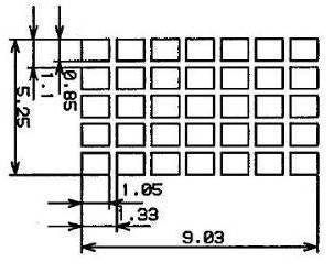
5 2. GENERAL SPECIFICATIONS NO ITEM Descriptions 1 Display method VFD display(blue green) 2 Number of columns 20 columns x 2 lines 3 Brightness 700 cd/ m 2 4 Character type 5 x 7 dot matrix 5 Character size mm x 9.03 mm 6 Fonts 96 alphanumeric 13 international 1 user define 14 code page 7 Command and driver ESC/POS and OPOS 8 MTBF (power on time) 30,000 hours 9 Viewing angle 0 ~ 45 degrees 10 Rotating angle 270 degrees (Max.) 11 Power supply Powered by USB, +5VDC and +9~+35VDC are optional 12 Power consumption 2.5W 13 Interface RS232C and USB are optional 14 Gross weight 1.7 Kg 15 External dimension Long Middle Short 225(W) x 100(D) 500(H)mm 225(W) x 100(D) 281(H)mm 225(W) x 100(D) 193(H)mm 16 Temperature 17 Humidity Operating 0 ~ 45 Storage -10 ~ 50 Operating 10%~90% Storage 10%~90% Table 2-1 4
6 3. UNPACKING AND CHECKING THE PARTS 3.1 Parts list (With Base PCB) (1) (2) (3) (4) (5) (6) (1) Display Module. (2) Nut. (3) Knob. (4) Neck. (5) Display Cable. (6) Long Pole (7) Short Pole (8) Base Housing. (9) Base PCB. (10) Power Adapter (11) AC Cord (12) Signal transmission line. (13) Plate. (7) (8) (12) (9) (10) (13) (11) 5
7 3.2 Parts list (Without Base PCB) (1) (4) (3) (1) Display Module. (2) Nut. (3) Knob. (4) Neck. (5) Long Pole (6) Short Pole (7) Base Housing. (8) Signal transmission line. (2) (5) (6) (7) (8) 6
8 3.3 Model Number WD-2030 X X X X Interface (Display Module) Base Type Power Input Color R: RS V S: RS-232 5V U: USB O: Power USB 5V P: Power USB 12V Q: Power USB 24V B: Black W: White R: RS-232 Base U: USB-B Base H: HUSB Base S: Only Rectangular Base Housing C: Only Circular Base Housing N: No Base M: Module + Neck Table 3-1 A: USA Cord + SPS B: Jap.Cord + SPS C: Eur. Cord + SPS D: U.K Cord + SPS E: Fra. Cord + SPS F: Asu.Cord + SPS G: SA. Cord + SPS Y: No AC Cord + SPS H: USA Cord + IEC I: Jap.Cord + IEC J: Eur. Cord + IEC K: U.K Cord + IEC L: Fra. Cord + IEC M: Asu.Cord + IEC N: SA. Cord + IEC Z: No AC Cord + IEC W: No AC Cord + No Power 1: USA Adaptor 2: Jap. Adaptor 3: Eur. Adaptor 4: U.K Adaptor 5: Fra. Adaptor 6: Asu. Adaptor 7: SA. Adaptor O: Power USB 5V P: Power USB 12V Q: Power USB 24V R: RS-232 Port(PC) S: RS-232 DC Jack + No Power U: USB Port(PC) V: USB Plug (POWER SUPPY) 7
9 4. Display Module Interface 4.1 RS232 Specifications Data transmission: Serial Synchronization: Asynchronous Handshaking: DTR / DSR MARK = -3 to 15 V (logic 1 ) Signal level: SPACE = +3 to +15 V (logic 0 ) Baud rates: 4800,9600,19200 or bps None parity, 8 data bits or Parity and bit length Even parity, 7 data bits Stop bits: 1 or more Table RS232 connector to PCB (CN1) Type: RJ45/8P/8C Pin assignment No Signal Direction Function description 1,2 Vin - Power +5VDC or +9~+35 VDC 3,4 GND - Signal ground 5 CTS From Printer to Display Printer ready signal 6 RTS From Display to PC/Host Display/Printer ready signal 7 RXD From PC/Host to Display Display/Printing data signal 8 TXD From Display to Printer Printer status data signal Table RS232 connector to PCB (CN6) Type: PH 2.0 mm/8p Pin assignment No Signal Direction Function description 1,2 Vin - Power 5VDC or 9~45 VDC 3,4 GND - Signal ground 5 CTS From Printer to Display Printer ready signal 6 RTS From Display to PC/Host Display/Printer ready signal 7 RXD From PC/Host to Display Display/Printing data signal 8 TXD From Display to Printer Printer status data signal Table 4-3 8
10 4.1.3 RS232 connector to PCB (CN7) Type: PH 2.0 mm/9p Pin assignment No Signal Direction Function description 1 NC TXD From Display to Printer Printer status data signal 3 RXD From PC/Host to Display Display/Printing data signal 4 CTS From Printer to Display Printer ready signal 5 GND - Signal ground 6,8 RTS From Display to PC/Host Display/Printer ready signal 7 NC Vin - Power +5 VDC or +9 ~ +35 VDC Table USB specifications Data transmission: USB emulation RS232C Synchronization: Asynchronous Handshaking: DTR / DSR Signal level: 0~+3V Baud rates: 4800,9600,19200 or bps Parity and bit length None parity, 8 data bits or Even parity, 7 data bits Stop bits: 1 or more Table USB connector to PCB (CN2) Type: WAFER PH 2.0mm 4P Pin assignment No Signal Direction Function description 1 V+ 5V From PC/Host USB power 5 VDC 2 D- Data signal - 3 D+ Data signal+ 4 GND Signal ground Table 4-6 9
11 4.3 Power USB specifications Data transmission: USB emulation RS232C Synchronization: Asynchronous Handshaking: DTR / DSR Signal level: 0~+3V Baud rates: 4800,9600,19200 or bps Parity and bit length None parity, 8 data bits or Even parity, 7 data bits Stop bits: 1 or more Table USB Connector to PCB (CN2+CN9) CN2 Type: WAFER PH 2.0mm 4P Pin assignment No Signal Direction Function description 1 V+ 5V From PC/Host USB power 5 VDC 2 D- Data signal - 3 D+ Data signal+ 4 GND Signal ground Table 4-8 CN9 Type: WAFER PH 2.0mm 5P Pin assignment No Signal Direction Function description 2,3 V+ 5/12/24V From PC/Host VPLUS 1,4 GND PWR Ground Signal ground 5 FG Data signal+ Table
12 5. Base PCB Interface 5.1 RS-232 Interface connector (On the bottom of the base section) CN1,CN6: +24VDC power supply pass-through connects CN2: Power input connector from adapter CN3: RS-232C connect to printer CN4: Connect to display panel CN5: RS-232C connect to PC/Host 5.2 Power Supply Connectors The variable power input which are available on base connectors, but only if one connector can be selected for power input, the description as below: CN2 / Type: DC jack (5.5/2.1) Pin assignment No Signal + Vin1 - GND Table CN1,CN6 / Type: Miniature jacks quick lock 3 pin Pin assignment No Signal 1 Vin2 2 GND Table CN5 / Type: DB25/F together with signals of RS-232C Pin assignment No Signal 16,25 Vin3 7 GND Table
13 5.4 RS232C link to PC/HOST connector (CN5) Type: DB25/F Pin assignment No Signal Direction Function description 2 TXD From printer to PC/Host Printer status data 3 RXD From PC/Host to display Receive data 4,20 DTR From display to PC/Host Display/printer ready signal 6 DSR From PC/Host to printer PC/Host ready signal 7 GND - Signal ground 16,25 Vin3 From PC/Host to display Power input Table RS232C link to printer connector (CN3) Type: DB9/M Pin assignment No Signal Direction Function description 2 RXD From printer to PC/Host Printer status data 3 TXD From display to printer Printing data 5 GND - Signal ground 4,7 DTR From PC/Host to printer PC/Host ready signal 6 DSR From printer to display Printer ready signal 9 Vin2 From Hosiden to printer Power through to printer Table RS232C link to display panel (CN4) Type: RJ45/8P/8C Pin assignment No Signal Direction Function description 1,2 Vin - Power +5VDC or +9~+35 VDC 3,4 GND - Signal ground 5 DSR From Printer to Display Printer ready signal 6 DTR From Display to PC/Host Display/Printer ready signal 7 RXD From PC/Host to Display Display/Printing data signal 8 TXD From Display to Printer Printer status data signal Table
14 6. USB BASE INTERFACE 6.1 USB Interface connector (On the buttom of the base section) CN1,CN6: +24VDC power supply pass-through connects CN2: Power input connector from adapter CN3: RS-232C connect to printer CN4: Connect to display panel CN5: USB input 6.2 Power Supply Connectors There are variable power inputs which are available on base connector, but only one connector can be selected for power input function, the description as below: CN1,CN6 / Type: Miniature jacks quick lock 3 pin Pin assignment No Signal 1 Vin2 2 GND Table CN2 / Type: DC jack (5.5/2.1) Pin assignment No Signal + Vin1 - GND Table

15 6.3 USB input port link to PC/HOST USB connector (CN5) Type: USB Pin assignment No Signal Direction Function description 1 V+ 5V From PC/Host USB power 5 VDC 2 D- Data signal - 3 D+ Data signal+ 4 GND - Signal ground Table RS232C link to printer connector (CN3) Type: DB9/M Pin assignment No Signal Direction Function description 2 RXD From printer to PC/Host Printer status data 3 TXD From display to printer Printing data 5 GND - Signal ground 4,7 DTR From PC/Host to printer PC/Host ready signal 6 DSR From printer to display Printer ready signal 9 Vin2 From Hosiden to printer Power through to printer Table RS232C link to display pannel (CN4) Type: RJ45/8P/8C Pin assignment No Signal Direction Function description 1,2 Vin - Power +5VDC or +9~+35 VDC 3,4 GND - Signal ground 5 DSR From Printer to Display Printer ready signal 6 DTR From Display to PC/Host Display/Printer ready signal 7 RXD From PC/Host to Display Display/Printing data signal 8 TXD From Display to Printer Printer status data signal Table
 OFF ON OFF UTC/P ON OFF OFF UTC/S OFF OFF OFF CD5220")
16 7. DIP SWITCH SETTING DIP ON 7.1 Command type selection SW1 SW2 SW3 Command type ON ON ON DSP800 OFF ON ON ESC/pos ON OFF ON PD3000 OFF OFF ON ADM 788 ON ON OFF EMAX(Aedex) OFF ON OFF UTC/P ON OFF OFF UTC/S OFF OFF OFF CD5220 Table 7-1 SW8 SW9 Baud rate (bps) ON ON 4800 OFF ON 9600 ON OFF OFF OFF Table Baud rate selection SW10 ON OFF 7.3 Parity check selection Parity & data bits None-parity, 8 data bits Even-parity, 7 data bits Table
17 7.4 International character set selection SW4 SW5 SW6 SW7 Character set Code table ( 80H-FFH) ON ON ON ON U.S.A. PC-437(USA&Europe) OFF ON ON ON France PC-858(Euro) ON OFF ON ON Germany PC-858(Euro) OFF OFF ON ON U.K. PC-858(Euro) ON ON OFF ON Denmark I PC-858(Euro) OFF ON OFF ON Sweden PC-858(Euro) ON OFF OFF ON Italy PC-858(Euro) OFF OFF OFF ON Spain PC-858(Euro) ON ON ON OFF Japan Katakana OFF ON ON OFF Norway PC-858(Euro) ON OFF ON OFF Denmark II PC-858(Euro) OFF OFF ON OFF U.S.A Slavonic ON ON OFF OFF U.S.A Russia OFF ON OFF OFF U.S.A PC860 (Portuguese) ON OFF OFF OFF U.K. Greek OFF OFF OFF OFF U.S.A WPC1257 Table 7-4 SW11 ON OFF * SW12 reserve 7.5 Self-test & demo function selection Function Enable Disable Table
18 8. COMMAND 8.1 CD5220 Standard Mode Command List Command Code (hex) Function description ESC DC1 1B 11 Overwrite mode ESC DC2 1B 12 Vertical scroll mode ESC DC3 1B 13 Horizontal scroll mode ESC QA...CR 1B data x m 0D Set the string display mode, writed string to upper line m 20 ESC QB...CR 1B data x m 0D Set the string display mode, writed string to lower line m 20 ESC QD...CR 1B data x m 0D Upper line message scroll continuously m 40 ESC [ D 1B 5B 44 Move cursor left BS 08 Move cursor left ESC [ C 1B 5B 43 Move cursor right HT 09 Move cursor right ESC [ A 1B 5B 41 Move cursor up ESC [ B 1B 5B 42 Move cursor down LF 0A Move cursor down ESC [ H 1B 5B 48 Move cursor to home position HOM 0B Move cursor to home position ESC [ L 1B 5B 4C Move cursor to left-most position CR 0D Move cursor to left-most position ESC [ R 1B 5B 52 Move cursor to right-most position ESC [ K 1B 5B 4B Move cursor to bottom position ESC l x y 1B 6C x y Move cursor to specified position 1 x 20,row position 1 y 2,column position 17
19 Command Code (hex) Function description 1B 40 Initialize display CLR 0C Clear display screen, and clear string mode CAN 18 Clear cursor line, and clear string mode ESC * n 1B 2A n Brightness adjustment 1 n 4 Define download characters. ESC & s n m 1B 26 1 n m [a(p1..pa)] 32 n m 255 [a (P1..pa)]x x (m-n+1) (m-n+1) 1 a 5 p1..p5 =row1..row5 ESC? n 1B 3F n Deletes download characters. 32 n m 255 ESC % n 1B 25 n Select/cancel download character set. n = 0, Cancel n = 1, Select ESC _ n 1B 5F n Set cursor on/off n = 1, cursor on n = 2, cursor off ESC f n 1B 66 n Select international fonts set, refer *2 ESC c n 1B 63 n Select code, refer *3 ESC = n 1B 3D n Select peripheral device, display or printer n bit 0 = 1 select printer n bit 1 = 1 select display Table
20 *2: The parameter of international fonts set control by command ESC f n Parameter n A G I J U F S N W D E L R International Font Set U.S.A. Germany Italy Japan U.K. France Spain Norway Sweden Denmark I Denmark II Slavonic Russia Table 8-2 *3: The parameter of the code table control by command ESC c n Parameter n A J L R International font set Compliance with ASCII code Compliance with JIS code Compliance with SLAVONIC code Compliance with RUSSIA code Table
21 8.2 UTC standard mode command list Command Code (hex) Function description EOT n 04 n Display Dimming n = 20h, 40h, 60h, FFh BS 08 Back space HT 09 Horizontal tab LF 0A Line feed CR 0D Carriage return DLE 0F Display position DC1 11 Over write display mode DC2 12 Vertical scroll mode DC3 13 Cursor on DC4 14 Cursor off CAN 18 Clear to end of line EM 19 Clear to end of display FS 1C Flashing text start GS 1D Flashing text end US 1F Reset display RS 1E Home and clear display ESC d 1B 64 Change to UTC enhanced mode Table
22 8.3 UTC enhanced mode command list Command Code (hex) Function description SI 0F Flashing text start SO 0E Flashing text stop ESC u A..CR 1B data x m 0D Upper line display 0 m 20 ESC u B..CR 1B data x m 0D Bottom line display 0 m 20 ESC u D..CR 1B data x m 0D Upper line message scroll continuously 0 m 40 ESC u E..CR 1B hh:mm 0D Display time 00 hh mm 59 ESC u F..CR 1B data x m 0D Upper line message scroll once pass ESC u H..CR 1B n m 0D Change attention code 32 n m 255 ESC u I..CR 1B data x m 0D Two line display 0 m 40 ESC RS CR 1B 0F 0D Change to UTC standard mode Table
23 8.4 AEDEX mode command list Command Code (hex) Function description! # 1...CR data x m 0D Upper line display 0 m 40! # 2...CR data x m 0D Bottom line display 0 m 40! # 4...CR data x m 0D Upper line message scroll continuously 0 m 40! # 5...CR hh:mm 0D Display time 00 hh mm 59! # 6...CR data x m 0D Upper line message scroll one pass 0 m 40 Change attention code! # 8...CR n m 0D 32 n m 255! # 9...CR data x m 0D Two line display 0 m 40 Table
24 8.5 PD3000 mode command list Command Code (hex) Function description DC2 12 Vertical Scroll Mode DC1 11 Normal Display Mode EOT 04 Brightness Control BS 08 Back Space HT 09 Horizontal Tab LF 0A Line Feed CR 0D Carriage Return DLE 10 Digit Select DC3 13 Cursor On DC4 14 Cursor Off US 1F Reset ETX 03 Down Load Font ENQ d1~d45 CR 05 d1~d45 0D Message Scroll SOH 01 Data to Peripheral! # STX Data to Display Table
25 8.6 ADM788 mode command list Command Code (hex) Function description CLR 0C Clear display CR 0D Carriage return SLE1 0E Clear up line and move cursor to upper line left most end SLE2 0F Clear low line and move cursor to lower line left most end DC0 n 10 n Set period to upper line last n position 31H n 44H DC1 n 11 n Set line blanking, n = 31H up line n = 32H low line DC2 n 12 n Clear line blanking, n = 31H up line n = 32H low line SF1 1E Clear field 1 and move cursor to field 1 fast position SF2 1F Clear field 2 and move cursor to field 2 fast position Table
26 8.7 DSP-800 mode command list Command Code (hex) Function descriptions EOT SOH I n ETB n 17 Select international character set. EOT SOH P n ETB n 17 Move cursor to specified position. 31H n 58H EOT SOH C n m ETB n m 17 EOT SOH S n ETB n 17 EOT SOH D n m ETB n m 17 EOT SOH A n ETB n 17 EOT SOH F n ETB n 17 EOT SOH & n [px5] ETB n p1...p5 17 EOT SOH? n ETB F n 17 EOT SOH = n ETB D n 17 Clear display range from n position to m position and move cursor to n position. 31H n m 58H Save the current displaying data to n layer for demo display. 31H n 33H Refer*1 Display the saved data 31H n 37H 31H m 37H Refer*2 Brightness adjustment. 31H n 34H Blink display screen. 0 n 255 Define download characters 20H < n FFH Delete download characters. 20H < n FFH Select peripheral device. n = 31H, select printer n = 32H, select display EOT SOH % ETB Initialize display EOT ETB Execute self-test Table
27 *REMARK WD-2030 XXXX customer display *1 Using commands EOT SOH S n ETB, the value (Hex) of parameter n Layer 31h Save data in layer 1 32h Save data in layer 2 33h Save data in layer 3 Table 8-10 *2 Using commands EOT SOH D n m ETB, the value (Hex) of parameter. WinPOS extended select mode from 33h to 37h n Select layer m Select mode 31h Demo layer 1 31h Demo mode 1 32h Demo layer 2 32h Demo mode 2 33h Demo layer 3 33h Demo mode 3 34h Demo layer h Demo mode h Demo layer h Demo mode h Demo layer h Demo mode h Demo layer h Demo mode Table
28 8.8 EPSON Esc/pos command list Command Code (hex) Function description HT 09 Move cursor right. BS 08 Move cursor left. US LF 1F 0A Move cursor up. LF 0A Move cursor down. US CR 1F 0D Move cursor to right-most position. CR 0D Move cursor to left-most position. HOM 0B Move cursor to home position. US B 1F 42 Move cursor to bottom position. US $ x y 1F 24 x y Move cursor to specified position. 1 x 20 1 y 2 CLR 0C Clear display screen. CAN 18 Clear cursor line US X n 1F 58 n Brightness adjustment. 1 n 4 US E n 1F 45 n Blink display screen. 0 n 255 1B 40 Initialize display. ESC t n 1B 74 n Select character code table. 0 n 7, 12, 16, 19, 40 Refer*2 ESC R n 1B 52 n Select international character set. 0 n 10 Refer*1 US r n 1F 72 n Select/cancel reverse character. 0 n 1 US MD1 1F 01 Specify overwrite mode. US MD2 1F 02 Specify vertical scroll mode. US MD3 1F 03 Specify horizontal scroll mode. Define download characters. ESC & s n m 1B 26 1 n m 32 n 255 [a(p1..pa)]x m-n [a(p1..pa)]x m-n 1 a 5 p1..p5 =row1..row5 27
29 Command Code (hex) Function description ESC? 1B 3F n Delete downloads characters. 32 n 255 ESC % 1B 25 n Select/cancel download character set. n = 0, Cancel n = 1, Select ESC = n 1B 3D n Select peripheral device. n bit 0 = 1 select printer n bit 1 = 1 select display US : 1F 3A Set starting/ending position of macro definition. US ^ n m 1F 5E n m Execute and quit macro. 0 n 255, 0 m 255 1F 40 Execute self-test. US T h m 1F 54 h m Display time 0 h 23, 0 m 59 US U 1F 55 Display time continuously US C n 1F 43 n Select / cancel cursor display n = 1, cursor on n = 0, cursor off Table
30 *REMARK WD-2030 XXXX customer display *1 Select international character set n International font 0 U.S.A. 1 France 2 Germany 3 U.K. 4 Denmark I 5 Sweden 6 Italy 7 Spain 8 Japan 9 Norway 10 Denmark II 11 Slavonic 12 Russia 13 Portuguese 14 Greek 15 Reserved Table 8-13 *2 Select character code table n Code table 0 Page 0, (PC437, USA standard Euro.) 1 Page 1,(Katakana for Japan) 2 Page 2,(PC850, Multilingual) 3 Page 3,(PC860, Portuguese) 4 Page 4,(PC863, Canadian-French) 5 Page 5,(PC865, Nordic) 6 Page 6,(Slavonic) 7 Page 7,(Russia) 19 Page 19,(PC858, Euro) 16 Page 16,(WPC1252.) 12 Page 12,(Greek) Table
 00 01 02 03 04 05 06 07 08 09")
31 9. CHARACTER SET 9.1 USA, standard character set (20h 7Eh) A 0B 0C 0D 0E 0F 20H 30H 40H 50H 60H 70H Table

32 9.2 International Character Sets Country\Hex B 5C 5D 5E 60 7B 7C 7D 7E U.S.A France Germany U.K Denmark I Sweden Italy Spain Japan Norway Denmark II Slavonic Russia Table

33 9.3 Page 0 (PC437: USA, Standard Europe) (80H FFH) A 0B 0C 0D 0E 0F 80H 90H A0H B0H C0H D0H E0H F0H Table

34 9.4 Page 1 (Katakana) (80H FFH) A 0B 0C 0D 0E 0F 80H 90H A0H B0H C0H D0H E0H F0H Table

35 9.5 Page 2 (PC850: Multilingual) (80H FFH) A 0B 0C 0D 0E 0F 80H 90H A0H B0H C0H D0H E0H F0H Table

36 9.6 Page 3 (PC860: Portuguese) (80H FFH) A 0B 0C 0D 0E 0F 80H 90H A0H B0H C0H D0H E0H F0H Table

37 9.7 Page 4 (PC863: Canadian-French) (80H FFH) A 0B 0C 0D 0E 0F 80H 90H A0H B0H C0H D0H E0H F0H Table

38 9.8 Page 5 (PC865: Nordic) (80H FFH) A 0B 0C 0D 0E 0F 80H 90H A0H B0H C0H D0H E0H F0H Table

39 9.9 Page 6 (Slavonic) (80H FFH) A 0B 0C 0D 0E 0F 80H 90H A0H B0H C0H D0H E0H F0H Table

40 9.10 Page 7 (Russia) (80H FFH) A 0B 0C 0D 0E 0F 80H 90H A0H B0H C0H D0H E0H F0H Table

41 9.11 Page 19 (PC858 Euro) (80H FFH) A 0B 0C 0D 0E 0F 80H 90H A0H B0H C0H D0H E0H F0H Table

42 9.12 Page 16 (WPC1252) (80H FFH) A 0B 0C 0D 0E 0F 80H 90H A0H B0H C0H D0H E0H F0H Table
43 9.13 Page 12 (Greek) (80H FFH) A 0B 0C 0D 0E 0F 80H 90H A0H B0H C0H D0H E0H F0H Table
44 9.14 Page 26 (WPC-1257) (80H FFH) A 0B 0C 0D 0E 0F 80H 90H A0H B0H C0H D0H E0H F0H Table
45 APPENDIX A: Display with Rectangle Base Dimension Unit : mm APPENDIX B: Display with Round Base Dimension Unit : mm 44
46 APPENDIX C: Rectangle Base Dimension Unit : mm APPENDIX D: Round Base Dimension Unit : mm 45
47 APPENDIX E: Tube Dimension Unit : mm 46

48 Unit : mm 47
49 APPENDIX F: Pass Through installation Guide PC/Host Display Printer *Only for CD5220/UTC/EMAX/EscPOS/DSP-800 emulation command sets. *If printer is EPSON TM serial printer then the pass through cable and display cable are same. 48
User s Manual Models CD5220 / CD6220. Vacuum Fluorescent Customer Display
 User s Manual Models CD5220 / CD6220 Vacuum Fluorescent Customer Display INDEX 1. FEATURES...3 2. TYPE CLASSIFICATION...4 3. GENERAL SPECIFICATIONS...5 4. INTERFACE SPECIFICATIONS...6 5. FUNCTION SELECTION...9
Customer Pole Display. Model: WD-304 Version: 1.12
 Customer Pole Display Model: WD-304 Version: 1.12 INDEX 1 FEATURES... 3 2 GENERAL SPECIFICATIONS... 4 3 UNPACKING... 5 3.1 PARTS LIST (WITH BASE PCB)... 5 3.2 PARTS LIST (WITHOUT BASE PCB)... 6 4 CONFIGURATION...
CD 8220 User Manual. LCD 2 x 20 Display
 CD 8220 User Manual LCD 2 x 20 Display INDEX 1. FEATURES...3 2. ORDER INFORMATION...4 3. GENERAL SPECIFICATIONS...5 4. INTERFACE SPECIFICATIONS...6 2 1. FEATURES 20 columns x 2 lines. Display panel is
VFD Series Vacuum Fluorescent Customer Display Instruction Manual ESC/POS commands Sets Supports
 VFD Series Vacuum Fluorescent Customer Display Instruction Manual ESC/POS commands Sets Supports Ver. 1.1 CONTENTS I. PRODUCT OVERVIEW... 3 Specification... 4 Package... 8 II. INSTALLING YOUR VFD CUSTOMER
MANUAL REVISION V EN1.0 ZQ-VFD2300. Vacuum Fluorescent Display Customer Display User s manual
 MANUAL REVISI V EN1.0 ZQ-VFD2300 Vacuum Fluorescent Display Customer Display User s manual INTRODUCTI CTENTS The product is a Vacuum Fluorescent Display, supporting English language. Features: Data can
DSP860 Operation Manual
 DSP860 Operation Manual 1. Information 2. Introduction 3. Installation 4. Pin Assignment 5. DIP Switch Setting 6. Character Tables 7. Software Control (Command List) 8. Specifications 9. Instruction of
DSP840 Operation Manual Version 3.0
 DSP840 Operation Manual Version 3.0 1. Information 2. Introduction 3. Installation 4. Pin Assignment 5. DIP Switch Setting 6. Character Tables 7. Software Control (Command List) 8. Specifications 9. Instruction
VFD CUSTOMER DISPLAY USER S MANUAL
 VFD CUSTOMER DISPLAY USER S MANUAL CONTENTS Contents... 1 Features... 2 Specifications - 9mm... 3 Block Diagram... 6 Interface Connections... 7 Usage Notes... 9 Switch Settings... 11 Firich Command Set
FEC-240G. Rev. Date
 Model User s Manual Contents Contents. 1 Features... 2 Type Model and Serial Number... 2 Specifications... 3 Interface Connections...... 4 DIP Switch Setting... 6 Dimension... 7 Command Set Table... 8
PD1100 STAND-ALONE PROGRAMMING & USER S GUIDE. use the freedom
 PD1100 STAND-ALONE ALPHANUMERIC POLE DISPLAY PROGRAMMING & USER S GUIDE use the freedom Forward The information contained in this user s guide is subject to change without notice. This Programming and
6. SOFTWARE CONTROL: COMMAND GROUP
 6. SOFTWARE CONTROL: COMMAND GROUP Command symbols definitions are as below: EOT 04H SOH 01H ETB 17H ESC 1BH US 1FH ACK 06H NACK 15H Group A. (command sets) A1. Package Command Format EOT SOH COMMAND ETB
J2 LCM Customer Display. Manual
 J2 LCM Customer Display Manual July 2012 Contents LCM Customer Display... 3 Overview... 3 Customer Display Configureation... 4 Port Settings... 4 CD Settings... 5 Emulation Mode... 5 Character Sets...
One station Impact Printer. Model: WP-300 Version : 1.03
 One station Impact Printer Model: WP-300 Version : 1.03 INDEX 1. GENERAL SPECIFICATION... 2 1.1 DESCRIPTION... 2 1.2 CHARACTERISTICS... 2 1.3 ACCESSORIES... 2 2. MAIN SPECIFICATION... 3 3. ILLUSTRATION...
Alphanumeric Operator Display
 Alphanumeric Operator Display Factory Built-in Option for FCX Keyboards TECHNICAL OVERVIEW Description and Application AlphanumericOperatorDisplay_TO_04.doc Version 4.0 October 3, 2007 TABLE OF CONTENTS
Control Command list (ESC/POS)
") Printer Command Control Command list (ESC/POS) Rev 1.4 1. Command Summary 2. Control Command 3. [STAR Emulation Mode] Command Summary SAM4S PRINTER ELLIX30/40 1 Control Command list 1. Command Summary
Printer Command Control Command list (ESC/POS) Rev 1.4 1. Command Summary 2. Control Command 3. [STAR Emulation Mode] Command Summary SAM4S PRINTER ELLIX30/40 1 Control Command list 1. Command Summary
1. Control Command List
 1. Control Command List Num Control Code Function 01 HT Horizontal tab 02 LF Print and line feed 03 CR Print and carriage return 04 DLE EOT n Real-time status transmission 05 DLE ENQ n Real-time response
XR-200 MINI DOT IMPACT PRINTER PRODUCT SPECIFICATION DATE : MAY 3, 2004 MANUAL REVISION 2.0
 XR-200 MINI DOT IMPACT PRINTER PRODUCT SPECIFICATI DATE : MAY 3, 2004 MANUAL REVISI 2.0 Features Dip Switch Configuration Emulation mode, communications mode, baud rate, serial/parallel handshake, and
DS-800. ::: Receipt Printer User s manual :::
 DS-800 ::: Receipt Printer User s manual ::: All specifications are subjected to change without notice TABLE OF CONTENTS 1. Parts Identifications 2 2. Setting up the printer 3 2.1 Unpacking 3 2.2 Connecting
TRP-100 Receipt Printer User s Manual
 TRP-100 Receipt Printer User s Manual All specifications are subject to change without notice TABLE OF CONTENTS 1. Parts Identifications 3 2. Setting up the printer 4 2.1 Unpacking 4 2.2 Connecting the
PD26xx/PD23xx/PD28xx Series Command Detail Manual
 PD26xx/PD23xx/PD28xx Series Command Detail Manual TABLE OF CONTENTS COMMEND EMULATION................................. 3-1 GENERAL CONCEPT.................................. 3-1 ADM EMULATION MODE..............................
Models: TD3000 Series. Table Displays. 2 by 20 character display USER MANUAL
 Models: TD3000 Series Table Displays 2 by 20 character display USER MANUAL i NOTICE The manufacturer of the POS table display makes no representations or warranties, either expressed or implied, by or
FEC-80T Receipt Printer User s Manual
 FEC-80T Receipt Printer User s Manual All specifications are subject to change without notice TABLE OF CONTENTS 1. Parts Identifications 3 2. Setting up the printer 4 2.1 Unpacking 4 2.2 Connecting the
Command Manual SRP-350 Thermal Printer Rev. 1.01
 Command Manual SRP-350 Thermal Printer Rev. 1.01 http://www.samsungminiprinters.com 1. Control Commands List Control codes Hexadecimal codes Function 09 Horizontal tab 0A Print and line feed
Command Manual Metapace T-2. Thermal Printer Rev. 1.00
 Command Manual Metapace T-2 Thermal Printer Rev. 1.00 1. Control Commands List Command HT LF FF CR CAN DLE EOT DLE ENQ DLE DC4 ESC FF ESC SP ESC! ESC $ ESC % ESC & ESC * ESC - ESC 2 ESC 3 ESC = ESC? ESC
Command Manual SPP-R200. Mobile Printer Rev
 Command Manual SPP-R200 Mobile Printer Rev. 1.03 http://www.bixolon.com Table of Contents 1. Notice... 3 2. Control Commands List... 3 3. Control Commands Details... 5 3-1 Command Notation... 5 3-2 Explanation
Dot Matrix Printer. SP2000 Series. Programmer s Manual
 Dot Matrix Printer SP2000 Series Programmer s Manual TABLE OF CONTENTS 1. Control Codes (Star Mode)... 1 1-1. Control Codes List... 1 1-1-1. Character Selection... 1 1-1-2. Print Position Control... 3
Models: LD9000 Series. Customer Displays. 2 by 20 character display USER MANUAL
 Models: LD9000 Series Customer Displays 2 by 20 character display USER MANUAL i NOTICE The manufacturer of the POS pole display makes no representations or warranties, either expressed or implied, by or
2D BARCODE SCANNER CA-SC-20200B
 D BARCODE SCANNER CA-SC-B Quick Start Guide Getting Familiar with Your Device Thank you for choosing Capture Bar Code Scanner. All Devices deliver world-class performance for a broad range of applications
MODEL : TRP-100-II Receipt Printer User s Manual
 MODEL : TRP-100-II Receipt Printer User s Manual All specifications are subject to change without notice Table of Contents 1. Parts Identifications 3 2. Setting up the printer 4 2.1 Unpacking 4 2.2 Connecting
PD1100 PASS-THROUGH PROGRAMMING & USER S GUIDE. use the freedom
 PD1100 PASS-THROUGH ALPHANUMERIC POLE DISPLAY PROGRAMMING & USER S GUIDE use the freedom Forward The information contained in this user s guide is subject to change without notice. This Programming and
Printer Control Command Set
 Printer Control Command Set Technical Manual Revision: November 1, 2017 Omniprint Inc. 1923 East Deere Ave., Santa Ana, California 92705, U.S.A. T: 949.833.0080 :: F: 949.833.0040 www.omniprintinc.com
TSP552 TSP552II TSP2000
 THERMAL PRINTER TSP552 TSP552II TSP2000 PROGRAMMER'S MANUAL Trademark acknowledgments TSP552, TSP552II, TSP2000: Star Micronics Co., Ltd. ESC/POS: Seiko Epson Corporation Notice All rights reserved. Reproduction
Addmaster Corporation
 IJ-1000 Ink-Jet Validation Printer Specification Addmaster Corporation Address: 225 East Huntington Drive Monrovia, CA 91016 Web: www.addmaster.com Phone: (626) 358-2395 FAX: (626) 358-2784 Document: ij1w.doc
MOBILE THERMAL PRINTER
 MOBILE THERMAL PRINTER MODEL CMP-20 series Technical Manual Rev. 1.00 TABLE OF CONTENTS 1. General Specifications 1.1 Printing Specifications 1.2 Character Specifications 1.3 Paper Specification 1.4 Printable
MODEL : LK-T200 Receipt Printer User s Manual
 SEWOO TECH CO.,LTD. Doosung BD, 689-20, Geumjeong-dong, Gunpo-si, Gyeonggi-do, 435-862, Korea TEL : +82-31-459-8200 FAX : +82-31-459-8880 www.miniprinter.com MODEL : LK-T200 Receipt Printer User s Manual
MP200 DOT MATRIX IMPACT PRINTER USER MANUAL
 MP200 DOT MATRIX IMPACT PRINTER USER MANUAL All specifications are subject to change without notice Disposal of Old Electrical & Electronic Equipment (Applicable in the European Union and other European
Command Manual SPP-R200. Mobile Printer Rev
 Command Manual SPP-R200 Mobile Printer Rev. 0.10 http://www.samsungminiprinters.com 1. Control Commands List COMMAND Name Funtion type 1 LF Print and line feed Print 2 FF Print and return to standard mode
MOBILE THERMAL PRINTER
 MOBILE THERMAL PRINTER MODEL CMP-30 series ESC Command Manual Rev. 1.00 TABLE OF CONTENTS 1. Command Description... 6 2. Commands... 7 HT... 7 LF... 7 CR... 8 FF... 8 CAN... 8 DLE EOT... 9 DLE ENQ... 12
WinPOS system. Co., ltd. WP-K837 series. Esc/POS Command specifications Ver.0.94
 WinPOS system. Co., ltd. WP-K837 series Esc/POS Command specifications 2014-05-06 Ver.0.94 LF Prints buffered data and feeds one line. Syntax: ASCII LF Hex 0A Decimal 10 Remarks: This command sets the
User s Manual BCD-1000 Series Customer Display Rev. 1.06
 User s Manual BCD-1000 Series Customer Display Rev. 1.06 http://www.bixolon.com Safety Precautions In using the present appliance, please keep the following safety regulations in order to prevent any hazard
MODEL : LK-T210 Receipt Printer User s Manual
 SEWOO TECH CO.,LTD. Doosung BD, 689-20, Geumjeong-dong, Gunpo-si, Gyeonggi-do, 435-862, Korea TEL : +82-31-459-8200 FAX : +82-31-459-8880 www.miniprinter.com MODEL : LK-T210 Receipt Printer User s Manual
4 Pr P i r n i t n e t r e Co C m o m m a m n a d n s d Li L s i t N. C m o m m a m n a d
 4. Printer Commands List NO. Command Function Description 01 HT Horizontal tab(#) 02 LF Print and line feed 03 CR Print and carriage return (#) 04 ESC SO Set all characters times width print 05 ESC DC4
SPP-R300 Command Manual Rev. 1.01
 Rev. 1.01 http://www.bixolon.com Contents 1. Notice... 3 2. SPP-R300 Supported Commands... 4 2-1 Command Description Items... 5 2-2 Details of Control Commands... 6 Rev. 1.01 BIXOLON - 2 - 1. Notice This
Tally Dascom DT-210/230 Programming Guide V1.1
 About This Manual Please read this technical manual before programming. Main description for command as below: 1) Function This is the first part of command description. Here we propose the command of
Mobile POS Thermal printer
 PK109 Mobile POS Thermal printer MEGADATA INDUSTRIAL, Inc. 1F, NO.10, Lane 58, Ta Chuan Street, TAICHUNG, TAIWAN R.O.C. TEL: +886-4-2376-6881 FAX: +886-4-2371-7974 www.posjet.com.tw megadata@ms21.hinet.net
SRP RECEIPT PRINTER. Operator s Manual. All specifications are subjected to change without notice
 SRP - 350 RECEIPT PRINTER Operator s Manual All specifications are subjected to change without notice Warning - U.S. This equipment has been tested and found to comply with the limits for a Class A digital
MPP6800 series - PANEL MOUNT PRINTERS. Options
 series - PANEL MOUNT PRINTERS Page 1 of 12 MPP6810 MPP6820 MPP6840 Introduction 5-8Vdc, 4A peak 5-8Vdc, 2A peak 10-35Vdc 24Vdc Features Easy load paper feature High resolution thermal printing 5-8Vdc standard,
SPP-R210 Command Manual Rev. 1.00
 Rev. 1.00 http://www.bixolon.com Contents SPP-R210 Command Manual 1. Notice... 3 2. SPP-R210 Supported Commands... 4 2-1 Command Description Items... 5 2-2 Details of Control Commands... 6 Rev. 1.00 BIXOLON
Vacuum Fluorescent Display Module GU-D series General Function Software Specification
 Vacuum Fluorescent Display Module GU-D series General Function Software Specification Model: GU-D series Specification No. : DS-1900-0002-02 Date of Issue : April 08, 2015 (00) Revision : June 29, 2015
MK D Imager Barcode Scanner Configuration Guide
 MK-5500 2D Imager Barcode Scanner Configuration Guide V1.4 Table of Contents 1 Getting Started... 3 1.1 About This Guide... 3 1.2 Barcode Scanning... 3 1.3 Factory Defaults... 3 2 Communication Interfaces...
The ICP 300 is an ultra-compact, lightweight portable thermal printer with an easy-load paper feature.
 THERMAL PRINTER Applications Datasheet Features Easy-Load paper feature RS232 Interface 10-35VDC Power Supply requirement High speed, high resolution printing capability Quiet, non-impact system Maintenance-free
MODEL : PR-T25 Receipt Printer User s Manual
 MODEL : PR-T25 Receipt Printer User s Manual All specifications are subject to change without notice Table of Contents 1. Parts Identifications 1. Parts Identifications 3 2. Setting up the printer 4 2.1
MODEL : AP-8220 U Receipt Printer User s Manual
 MODEL : AP-8220 U Receipt Printer User s Manual AP-8220 U Rev.A 10/14 All specifications are subject to change without notice Table of Contents 1. Parts Identifications 1. Parts Identifications 3 2. Setting
PD-2300 Series USER S MANUAL. VFD CUSTOMER DISPLAY for ALPHANUMERICAL DISPLAY in 2 x 20 format. Rev. : Original
 2100 2200 PD-2300 Series USER S MANUAL VFD CUSTOMER DISPLAY for ALPHANUMERICAL DISPLAY in 2 x 20 format Rev. : Original FCC NOTICE SOME IMPORTANT NOTES This equipment generates, uses, and can radiate radio
MODEL : SLK-TL100 Receipt Printer User s Manual
 J. STEPHEN Lab., Ltd. 28-6, Gajangsaneopdong-ro, Osan-si, Gyeongi-do, 447-210, Korea TEL : +82-31-459-8200 FAX : +82-31-459-8880 www.miniprinter.com MODEL : SLK-TL100 Receipt Printer User s Manual TL100
COMBINATION PRINTER SCP700 SERIES
 COMBINATION PRINTER SCP700 SERIES Programmer s Manual Trademark acknowledgments SCP700: Star Micronics Co. Ltd. ESC/POS, TM-295, TM-T85: Seiko Epson Corporation Notice All rights reserved. Reproduction
MODEL : SLK-D10 Mini Dot Impact Printer
 MODEL : SLK-D10 Mini Dot Impact Printer All specifications are subject to change without notice 1 Table of Contents 1. Features 3 2. Specification 4 3. Self Test 6 4. Configuration Setup 7 5. User Switches
Fics-RT1. User s Manual
 Fics-RT1 User s Manual Contents 1: Overview... 1 2: Terminal Specifications... 1 2-1: Standard Specifications... 1 2-2: Customer Defined Features:... 1 3: Terminal RS232C Communication Link Details...
MODEL : LK-TL200 Receipt Printer User s Manual
 SEWOO TECH CO.,LTD. 28-6, Gajangsaneopdong-ro, Osan-si, Gyeongi-do, 447-210, Korea TEL : +82-31-459-8200 FAX : +82-31-459-8880 www.miniprinter.com MODEL : LK-TL200 Receipt Printer User s Manual TL200 Rev.
SRP-275III Command Manual Rev. 1.00
 Rev. 1.00 http://www.bixolon.com Contents 1. Notice... 3 2. SRP-275III Supported Commands... 4 2-1 Command Description Items... 5 2-2 Details of Control Commands... 6 Rev. 1.00 BIXOLON - 2 - 1. Notice
PANDA Thermal Receipt Printer. Programmer Manual
 PANDA Thermal Receipt Printer Programmer Manual 1. COMMANDS 1.1 Command Notation The name of the command. [Format] The code sequence. [Range] Gives the allowable ranges for the arguments. Describes the
MODEL : SLK-TE20X Series Receipt Printer User s Manual
 MODEL : SLK-TE20X Series Receipt Printer User s Manual TE20X Series Rev.F 03/16 All specifications are subject to change without notice Table of Contents 1. Parts Identifications 1. Parts Identifications
RS-422 Code-Operated Switches
 JUNE 2000 SW421A-R2 SW422A-R2 RS-422 Code-Operated Switches COS/4 TEXT TRANSPARENT GRAPHICS MODE RESET ST LO CUSTOMER SUPPORT INFORMATION Order toll-free in the U.S. 24 hours, 7 A.M. Monday to midnight
SRP-275II Impact Printer Command Manual
 SRP-275II Impact Printer Command Manual Contents 1. Notice...3 2. SRP-275II Supported Commands...4 2-1 Command Description Items...5 2-2 Details of Control Commands...6 Rev. 1.00 BIXOLON - 2 - 1. Notice
PD 309 / 2605 Series User s Manual
 PD 309 / 2605 Series User s Manual Rev. A0 FCC Notes: This equipment generates, uses, and can radiate radio frequency energy and, if not installed and used in accordance with the instructions manual, may
BARCODE SCANNER. FUZZYSCAN FAMILY Quick Start Guide
 BARCODE SCANNER FUZZYSCAN FAMILY Quick Start Guide Getting Familiar with Your FuzzyScan Thank you for choosing Cino FuzzyScan Bar Code Scanner. All FuzzyScan scanners deliver world-class performance for
Mobile Printer. Command Manual Ver Models: SM series
 Mobile Printer Command Manual Ver. 1.9 Models: SM series CONTENTS 1. Printer Control Function...3 1.1. Print Commands...5 1.2. Line Spacing Commands....7 1.3. Character Commands...8 1.4. Print Position
User s Manual BCD-2000 Customer Display Rev. 1.00
 User s Manual BCD-2000 Customer Display Rev. 1.00 http://www.bixolon.com Introduction BCD-2000 is designed to be used while connected to computer peripherals and electronic devices such as ECR (Electronic
Vacuum Fluorescent Display Module Type 3900B series General Function Software Specification
 Vacuum Fluorescent Display Module Type 3900B series General Function Software Specification Model: GU-3900B series Specification No: DS-1600-0008-00 Date of Issue: October 27, 2010 (00) Revision: Published
User Manual. June 2008 Revision 1.7. P07303 Series Customer Display
 User Manual June 2008 Revision 1.7 P07303 Series Customer Display Copyright 2008 August All Rights Reserved Manual Version 1.7 The information contained in this document is subject to change without notice.
PRODUCT INFORMATION. MPP5500 Series PANEL-MOUNT PRINTERS
 PRODUCT INFORMATION Series PANEL-MOUNT PRINTERS Applications Datasheet Features Easy load paper feature High speed, high resolution printing 5Vdc, 10-35Vdc or low power Quiet, non-impact system Maintenance-free
PD 330 / 2606 Series User s Manual
 PD 330 / 2606 Series User s Manual Rev. B0 FCC Notes: This equipment generates, uses, and can radiate radio frequency energy and, if not installed and used in accordance with the instructions manual, may
Vacuum Fluorescent Display Module. Specification No: Model: CU24043-Y100. Date of Issue: January 29, 2009 (00) Revision: February 19, 2010 (01)
 Revision: February 19, 2010 (01)") RoHS 2002/95/EC Vacuum Fluorescent Display Module Specification Model: CU24043-Y100 Specification No: DS-1570-0001-01 Date of Issue: January 29, 2009 (00) Revision: February 19, 2010 (01) Published by
RoHS 2002/95/EC Vacuum Fluorescent Display Module Specification Model: CU24043-Y100 Specification No: DS-1570-0001-01 Date of Issue: January 29, 2009 (00) Revision: February 19, 2010 (01) Published by
MODEL : TRP100-III Receipt Printer User s Manual
 MODEL : TRP100-III Receipt Printer User s Manual All specifications are subject to change without notice A software tool is available to configure the printer settings on AURES technical website: www.aures-support.fr
NC-1200 BARCODE SCANNER. Configuration Guide - 1 -
 NC-1200 BARCODE SCANNER Configuration Guide - 1 - Table of Contents Chapter 1 System Information 1.1 About this manual 3 1.2 How to set up the parameter-i 3 1.3 How to set up the parameter II 4 1.4 Resetting
A GUIDE TO RS-232 COMMUNICATION WITH FX PLCS
 A GUIDE TO RS-232 COMMUNICATION WITH FX PLCS Page 1 of 35 A GUIDE TO RS-232 COMMUNICATION WITH FX PLCS This document has been written specifically for FX and FX0N users that are unfamiliar with RS-232
User Manual September 2009 Revision 1.9. P07303 Series Customer Display
 User Manual September 2009 Revision 1.9 P07303 Series Customer Display Copyright September 2009 All Rights Reserved Manual Version 1.9 The information contained in this document is subject to change without
MODEL : SLK-T12EB Receipt Printer User s Manual
 J. STEPHEN Lab., Ltd. 28-6, Gajangsaneopdong-ro, Osan-si, Gyeonggi-do, 447-210 Republic of Korea TEL : +82-31-8077-5000 FAX : +82-31-459-8880 www.miniprinter.com MODEL : SLK-T12EB Receipt Printer User
Command Emulator ESC/POS Mode Command Specifications
 Line Thermal Printer ESC/POS Mode Command Specifications Revision 1.02 Star Micronics Co., Ltd. Special Products Operating Division TABLE OF CONTENTS 1....1-1 1-1) Command List... 1-1 1-2) COMMAND DETAILS...
COPYRIGHT 2009,SCSC. Manual P/No: SCCM - 80S-01A Released Date: Oct 31, 2009
 To begin the configuration procedures Thank you for purchasing the scanner. Inside each packaging box, you may find the scanner, the interface cable and user's fuide. Configuration manual might be optional
Vorne Industries. 2000S Series Serial Input Alphanumeric Display User's Manual
 Vorne Industries 2000S Series Serial Input Alphanumeric Display User's Manual 1445 Industrial Drive Itasca, IL 60143-1849 Telephone (630) 875-3600 Telefax (630) 875-3609 2000S Series Serial Input Alphanumeric
Laser Barcode Scanner ARP Nr User s Manual
 Laser Barcode Scanner ARP Nr. 853782 User s Manual FCC Compliance This equipment has been tested and found to comply with the limits for a Class B digital device, pursuant to Part 15 of the FCC Rules.
STP-103II Thermal Printer Command Manual
 Thermal Printer Command Manual Contents 1. Notice... 3 2. Control Commands List in Alphanumeric Order... 4 2-1 Command Description Items... 6 2-2 Details of Control Commands... 7 Rev. 1.02 BIXOLON - 2
BARCODE SCANNER. Configuration Guide - 1 -
 BARCODE SCANNER Configuration Guide - 1 - Table of Contents Chapter 1 System Information 1.1 About this manual 3 1.2 How to set up the parameter 3 1.3 How to set up the parameter - II 4 Chapter 2 System
QTERM-J10/N15 USER'S MANUAL REVISION 13
 QTERM-J0/N5 USER'S MANUAL REVISION 3 M0-009-00 Rev 3 QSI CORPORATION 222 South West Temple #50 Salt Lake City, UTAH 845-2648 USA Phone 80-466-8770 Fax 80-466-8792 Email info@qsicorp.com Web www.qsicorp.com
Dot Matrix Printer. SP300 Series. Programmer s Manual
 Dot Matrix Printer SP300 Series Programmer s Manual TABLE OF CONTENTS 1. CONTROL PANEL... 1 1-1. Basic Operation... 1 1-2. Switch Operation (Combined Switch Operation)... 2 2. SERIAL INTERFACE... 7 2-1.
User s Manual. Multimedia Customer Pole Display
 User s Manual Multimedia Customer Pole Display Contents 1. General Information...1 1.1 Features...2 1.2 Size...2 1.3 Introduction and Specifications...3 2. Standard Package... 错误! 未定义书签 3. Hareware Installation...3
SRP-330 Command Manual Rev. 1.01
 Command Manual Rev. 1.01 http://www.bixolon.com Contents 1. Notice... 3 2. Control Commands List in Alphanumeric Order... 4 2-1 Command Description Items... 6 2-2 Details of Control Commands... 7 Rev.
Mounting Dimensions / Viewing 2 Mounting Options 3. Wiring Configuration 4. Quick Set up Procedure 5. Changing Intensity 6.
 Section Mounting Dimensions / Viewing 2 Mounting Options 3 Section 2 Wiring Configuration 4 Section 3 Quick Set up Procedure 5 Section 4 Changing Intensity 6 Section 5 Option Summary 7 Section 6 Option
ADDMASTER. Addmaster Corporation. IJ-3080 Journal/Validation Printer. Specification. IJ-3080 Specification
 IJ-3080 Journal/Validation Printer Specification Provides the electrical, mechanical, and interface specifications of the IJ-3080 Journal/Validation Printer. Cover Models: IJ-3080 The Addmaster Model IJ-3080
SRP-F310/312 Command Manual Rev. 1.00
 Command Manual Rev. 1.00 http://www.bixolon.com Contents 1. Notice...3 2. Control Commands List in Alphanumeric Order...4 2-1 Command Description Items...6 2-2 Details of Control Commands...7 Rev. 1.00
Universal Asynchronous Receiver Transmitter Communication
 Universal Asynchronous Receiver Transmitter Communication 13 October 2011 Synchronous Serial Standard SPI I 2 C Asynchronous Serial Standard UART Asynchronous Resynchronization Asynchronous Data Transmission
[Notes] Provides important information on setting and using the printer command, if necessary.
![[Notes] Provides important information on setting and using the printer command, if necessary.](/thumbs/95/122526477.jpg "[Notes] Provides important information on setting and using the printer command, if necessary.") 2. COMMANDS 2. 1 Command Notation X X X X [Name] The name of the command. [Format] The code sequence. [Range] Gives the allowable ranges for the arguments. [Description] Describes the command s function.
2. COMMANDS 2. 1 Command Notation X X X X [Name] The name of the command. [Format] The code sequence. [Range] Gives the allowable ranges for the arguments. [Description] Describes the command s function.
Lecture (09) x86 programming 8
 x86 programming 8") Lecture (09) x86 programming 8 By: Dr. Ahmed ElShafee 1 Basic Input Output System BIOS BIOS refers to a set of procedures or functions that enable the programmer have access to the hardware of the computer.
Lecture (09) x86 programming 8 By: Dr. Ahmed ElShafee 1 Basic Input Output System BIOS BIOS refers to a set of procedures or functions that enable the programmer have access to the hardware of the computer.
MODEL : SLK-TS400EB. Receipt Printer User s Manual. TS400EB Rev. B 07/16. All specifications are subject to change without notice
 MODEL : SLK-TS400EB Receipt Printer User s Manual TS400EB Rev. B 07/16 All specifications are subject to change without notice Table of Contents 1. Parts Identifications 1. Parts Identifications 3 2.
REV: PAGE: REVISION DESCRIPTION APPR: DATE: A ALL Released to production GRW 6/17/94
 PAGE: REVISION DESCRIPTION APPR: DATE: A ALL Released to production GRW 6/17/94 B 5 Maximum component height was 10.5mm; Removed through hole crystal note and dimension; GRW 3/23/95 Released to production
PureScan - ML1. Configuration Guide. Wireless Linear Imager Wireless Laser scanner - 1 -
 PureScan - ML1 Wireless Linear Imager Wireless Laser scanner Configuration Guide - 1 - Table of Contents Chapter 1 System Information 1.1 About this manual 3 1.2 How to set up the parameter 3 Chapter 2
EXPERIMENT 8: Introduction to Universal Serial Asynchronous Receive Transmit (USART)
") EXPERIMENT 8: Introduction to Universal Serial Asynchronous Receive Transmit (USART) Objective: Introduction To understand and apply USART command for sending and receiving data Universal Serial Asynchronous
EXPERIMENT 8: Introduction to Universal Serial Asynchronous Receive Transmit (USART) Objective: Introduction To understand and apply USART command for sending and receiving data Universal Serial Asynchronous
Start Configuration. Chap.1 System Information. Set All default
 SC2100B Chap.1 System Information Set All default S/W Version Chap.2 System Installation 2.1 Interface Selection If you change the interface from others to USB, the program needs to restart plug the installation.
PD / 2602 Series User s Manual
 PD - 2601 / 2602 Series User s Manual Rev. A0 FCC Notes: This equipment generates, uses, and can radiate radio frequency energy and, if not installed and used in accordance with the instructions manual,