Discharge by touching: BNC coax shield, outlet metal cover plate, wire connected to GND
|
|
|
- Lewis Parker
- 5 years ago
- Views:
Transcription
1 Step-down transformer Very High Voltage Very Low Current Lower Voltage, 110V Power Station Grounding contact (3rd wire) Faulty wiring makes box hot!! Current path splits: 1) to ground (mostly) 2) through you (very little) Excess current blows breaker. Static Electricity 1. e- builds up by rubbing (High Voltage) 2. e- jumps (very low current, but enough) Discharge by touching: BNC coax shield, outlet metal cover plate, wire connected to GND
2 WARNING NO short circuit power supply: NO wire connection from voltage source to ground. Destroys power transformer. Wiring mistakes cause this. TEST VOLTAGES AS YOU MAKE CONNECTIONS. Plug the 0v and 5v power supply lines together: Short Circuit Power Supply overheats and burns out.


3
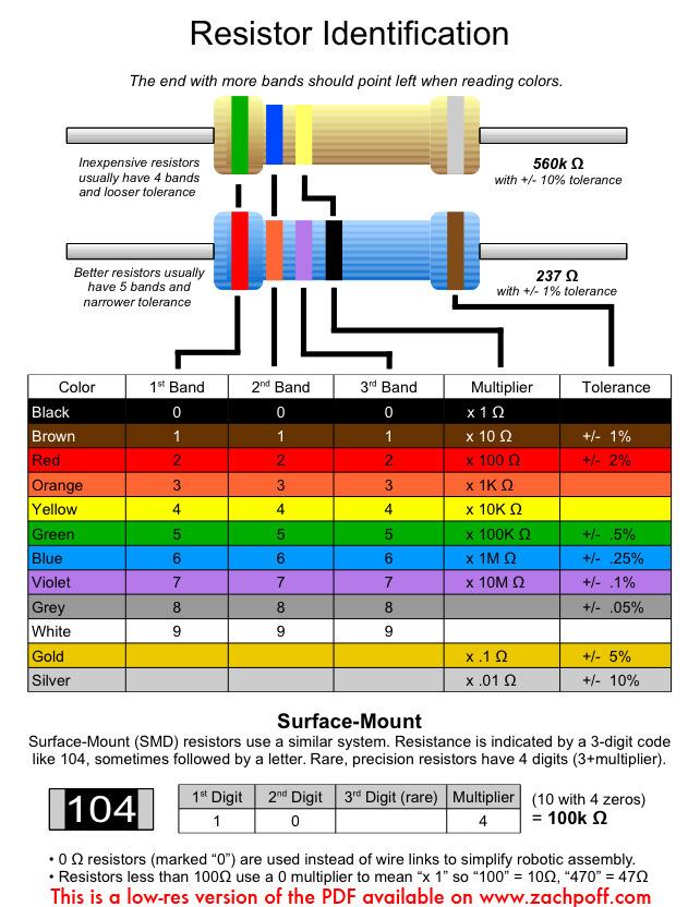
4 Resistors
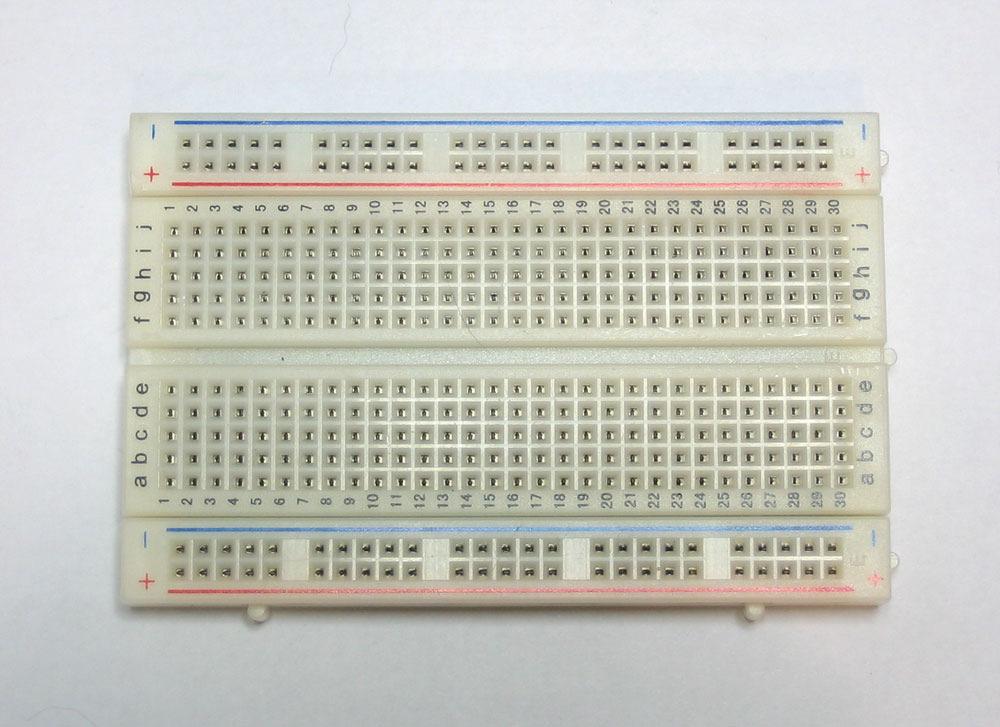
5 1. Measure voltage at +5v supply a. connect black probe to GND b. touch red probe to +5v supply Q. What voltage do you read? 2. Measure voltage at GND Q. What voltage do you read? Holes are connected together underneath board. A. voltage is measured difference BETWEEN two physical contacts. B. One contact can be GROUND, which is nominally 0 v. C. Voltage ACROSS a device is difference between one side of device and other side. 3. Touch meter's leads to R1's leads. Q. What is the voltage across R1? D. To measure voltage across a device, touch meter's leads to wires from device, black to one side, red to the other. 4. Touch meter's leads to R2's leads. Q. What is the voltage across R2? 5. Touch meter's leads input/output wires of the R1+R2 combination. Q. What is the voltage across R1+R2? 6. Which way is the current flowing through R1? 7. Which way is the current flowing through R2? 8. How much current is flowing?
6 NB--Ground contacts are labeled, but the BNC connector's external metal is also ground; you can push your ground probe into the BNC connector so that it rests between the plastic core and the metal case. 9. What is the voltage at the point between R1 and R2, relative to GND? 10. What is the voltage between R1 and R2, relative to the +5v supply? 11. At left is a circuit someone wired on a breadboad. They used the holes in a single connected 5-group. The wire connecting the holes is shown in gray. Q. Complete the circuit diagram shown below for this circuit, explaining which parts of the diagram correspond to which parts of the physical circuit. 12. Explain what will happen to this set up when the board is supplied power. Q. That is, was is the power loss as heat between the terminals A and B?
7 an LED (Light Emitting Diode) circuit 13. Depending on the LED, the resistance needs to more or less. Use a larger resistance, and if no light shows, change to a smaller resistance. Q. Measure voltage drops across resistor and LED.

8 We have: PN2222 or 2N4401 or BC337 npn Bipolar Transistors Base B must have a RESISTOR attached. Else, transistor will BURN UP.
9 14. Setting the input switch to 0, measure voltage drops across resistors and transistor terminals: data switch VRB, VRup, VCE, VBE, VCB 15. Setting the input switch to 0, measure voltage drops across resistors and transistor terminals: VRB, VRup, VCE, VBE, VCB 16. Set the data switch to 0. Measure the voltage at the input relative to ground. Disconnect the output from the LED and measure the output voltage relative to GND. Fill in the first row of the table at right. 17. Set the data switch to 1. Make the same measurements and fill in the second row of the table.


10 Here's how we use TTL chips on our breadboard. This circuit includes a set of switches and and LED output indicator. The chip has its VCC pin connected to the +V rail, and its GND pin connect to to the GND rail. The input switches have pullup resistors, and are wired as manual NOT gates. The LED has a resistor. There is a capacitor across the power pins of the chip. NB has its inputs/outputs left-right flipped w.r.t. the IF YOU rotate by 180 degrees (swapping GND and +5v) they look the same.
11 Do NOT tie gate outputs to Supply or Ground. Each device has +5v and GND supplies. Device logic output goes to Device logic input Device current is small logic output to GND ==> excess current. logic output to +5v ===> SHORT CIRCUIT NB-- Different symbols for transistors of different types. Both are switches controlled by the B input. Bi-Polar nmos Do NOT tie gate outputs together. Which output determines the value of x? A = 0, B = 1, x =? A = 1, B = 0, x =? input X A=0 B=0 1 A=0 B=1 0 A=1 B=0 0 A=1 B=1 0 Just so happens to be NOR( A, B) Probably not what you were thinking.
 = NOT( OR(x, y) ) NAND( x, y) = NOT( AND(x, y) ) TTL chips: 7400 (four NANDs), 7402 (four NORs), and 7404 (six")

12 Two types of logic circuits: --- feedback (sequential circuits) ===> Sequential circuits hold state --- no feedback (combinational circuits) ===> purely functional, cannot hold state Basic logic gates: NOT, NOR, NAND --- Combine to get any function or state machine NOR( x, y) = NOT( OR(x, y) ) NAND( x, y) = NOT( AND(x, y) ) TTL chips: 7400 (four NANDs), 7402 (four NORs), and 7404 (six NOTs) Combinatorial circuit --- no feedback Sequential circuit --- feedback TTL chips fit across breadboard channel NAND has four NAND gates. Each gate has three pin connections: in-a, in-b, out-y. NOTE: 7402 NOR has different pin pattern left-to-right: out-y, in-a, in-b. Use a chip puller to remove chips: --- leads are easily bent --- hard to straighten Leave room between chips to get puller in

13 Logic Probe May be inaccurate. Check signal w/ volt meter to be sure.
14 1. Use a 7404 NOT to build this circuit: 1.a What are the voltages at A and B? (Use the volt meter). 1.b What are the logic values at A and B? (Use the logic probe). 1.c Briefly connect, then immediately disconnect a wire from A to GND. Now measure A and B (use both methods). 1.d Now make the same connection at B instead, and measure A and B. 1.e Is this a sequential or combinatorial circuit? How many states does this circuit have? 2. Use a 7400 NAND, connect one gate's inputs to switches, and use your logic probe to see the output. 2.a Complete the following truth table for NAND: in out A B Y ========== b Consider A to be a control signal, and set the A input to logic 1. Toggle the B input (switch from 0 to 1 to 0). Explain how Y is logically related to input B. 2.c Now set A to 0, and toggle B. Now how is Y related to B? 3. Build the circuit at right. 3a. How does this ckt compare with the NOT-NOT ckt above (Use same testing procedure as you did for the NOT-NOT circuit.) 3b. Switch the input A to 0. What is the effect at Q? 3c. Switch A back to 1, then switch data B to 0. What is the effect at Q?

15 Clean wiring Although the larger, "bonded" flexible jumper wires are easy to plug in, they soon become a tangled mess. This makes it hard to debug a ciruit. Better to use small pieces of wire layed down neatly and flat. Do not cross wire over your chip as you may want to pull it off your board. At right is a 7400 wired as in part 3 above w/ short, flat wires. The jumpers are away from chip's pins, making it easy to see and probe. NB--By pulling out the 7400 and putting in a 180- degree rotated 7402 NOR chip instead, you will have wired the circuit shown below for part 4. Of course, you have to change upper-left pin to be connected to GND, and the lower-right pin to be connected +5v. "SW-A" indicates one of the data switches. Working w/ small wires and chip pins. Pliers are needed to straighten small wires and firmly push them into the breadboard holes. Chip pins may need to be straightened and aligned. Use pliers to gently bend them. They break if bent too far. Gently align the pins to the holes so they all go in together. DANGER Do not leave a chip on the floor or out on a desktop: The pins are VERY SHARP.
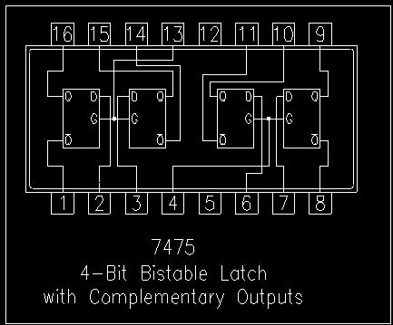
16 4. Repeat (2) and (3) using a 7402 NOR. 4.a How does the NOR-NOR ckt compare with the NAND-NAND ckt? 4.b What is the fundamental difference between them? The circuits above are basic elements that remember a binary state, once it is set. But, we cannot control which state they are in. We need a control, Enable (E), and a Data (D) input. 5. Build the circuit below. This is a latch. The circuit above is a "D-latch with enable". 5.a Set E = 1, D = 1. What is Q? 5.b Set E = 0. What is Q? 5.c Set D = 0. What is Q? 5.d Set E = 1, D = 1. What is Q? 5.e Set D = 0. What is Q? 5.f Set E = 0. What is Q? 5.g Set D = 1. What is Q?
17 Sequential Machine: --- Has state --- Changes its state --- A function determines the next state --- Input to the function is the current state The next-state function is a combinatorial circuit Machine's state is a sequential ciruit --- We built a state-element circuit, the D-latch The D-latch acts like a wire passing D to the Q whenever E = 1. If we use a latch for our state element in our sequential machine, it will not change state when we want it to. Suppose the next-state function is NOT. What will happen? 6. Build the circuit at right. 6.a Set E = 1. Set E = 0. Repeat several times. What state did it settle to each time E = 0? The problem with the circuit above is that the next-state signal goes through the latch and changes the machine's state before we can set E = 0 again. We need a controlled way to do this. We use two latches, and only set one of the E's to 1 at a time, the other is 0. This state element is a D-Flip-Flop. Only one of the enables is allowed to be logic 1.
18
19
20
Drexel University Electrical and Computer Engineering Department ECE 200 Intelligent Systems Spring Lab 1. Pencilbox Logic Designer
 Lab 1. Pencilbox Logic Designer Introduction: In this lab, you will get acquainted with the Pencilbox Logic Designer. You will also use some of the basic hardware with which digital computers are constructed
Digital Circuits. Page 1 of 5. I. Before coming to lab. II. Learning Objectives. III. Materials
 I. Before coming to lab Read this handout and the supplemental. Also read the handout on Digital Electronics found on the course website. II. Learning Objectives Using transistors and resistors, you'll
Physics 120/220 Lab Equipment, Hints & Tips
 Physics 120/220 Lab Equipment, Hints & Tips Solderless Breadboard... 2 Power supply... 4 Multimeters... 5 Function generator... 5 Oscilloscope... 6 10X probe... 7 Resistor color code... 7 Components...
Finite State Machine Lab
 Finite State Machine Module: Lab Procedures Goal: The goal of this experiment is to reinforce state machine concepts by having students design and implement a state machine using simple chips and a protoboard.
CSC 258 lab notes, Fall 2003
 CSC 258 lab notes, Fall 2003 Instructor: E. R. C. Hehner Lab demonstrators: Nicolas Kokkalis, Andrés Lagar Cavilla Successful completion of the three graded labs in this course involves a significant amount
ECE 270 Lab Verification / Evaluation Form. Experiment 1
 ECE 70 Lab Verification / Evaluation Form Experiment Evaluation: IMPORTANT! You must complete this experiment during your scheduled lab period. All work for this experiment must be demonstrated to and
Lab 4: Digital Electronics Innovation Fellows Program Boot Camp Prof. Steven S. Saliterman
 Lab 4: Digital Electronics Innovation Fellows Program Boot Camp Prof. Steven S. Saliterman Exercise 4-1: Familiarization with Lab Box Contents & Reference Books 4-1-1 CMOS Cookbook (In the bookcase in
Button Code Kit. Assembly Instructions and User Guide. Single Button Code Entry System
 Button Code Kit Single Button Code Entry System Assembly Instructions and User Guide Rev 1.0 December 2009 www.alan-parekh.com Copyright 2009 Alan Electronic Projects Inc. 1. Introduction... 4 1.1 Concept
1/Build a Mintronics: MintDuino
 1/Build a Mintronics: The is perfect for anyone interested in learning (or teaching) the fundamentals of how micro controllers work. It will have you building your own micro controller from scratch on
Massachusetts Institute of Technology Department of Electrical Engineering and Computer Science Introductory Digital Systems Laboratory
 Massachusetts Institute of Technology Department of Electrical Engineering and Computer Science 6.111 -- Introductory Digital Systems Laboratory NUBUS LABORATORY KIT For your pleasure and convenience,
E85: Digital Design and Computer Engineering Lab 1: Electrical Characteristics of Logic Gates
 E85: Digital Design and Computer Engineering Lab 1: Electrical Characteristics of Logic Gates Objective The purpose of this lab is to become comfortable with logic gates as physical objects, to interpret
COS 116 The Computational Universe Laboratory 7: Digital Logic I
 COS 116 The Computational Universe Laboratory 7: Digital Logic I In this lab you ll construct simple combinational circuits in software, using a simulator, and also in hardware, with a breadboard and silicon
Lab 4: Digital Electronics BMEn 2151 Introductory Medical Device Prototyping Prof. Steven S. Saliterman
 Lab 4: Digital Electronics BMEn 2151 Introductory Medical Device Prototyping Prof. Steven S. Saliterman Exercise 4-1: Familiarization with Lab Box Contents & Reference Books 4-1-1 CMOS Cookbook (In the
Theme 2: Introduction to Digital systems
 Theme 2: Introduction to Digital systems Power supply integrated circuits Connecting microswitches Using LEDs to visualize outputs Visualization using a common anode display Troubleshooting Guide Datasheets
EECE 2411/2211-Introduction to Electrical and Computer Engineering Lab. Lab 3
 EECE 2411/2211-Introduction to Electrical and Computer Engineering Lab Lab 3 Building Multi-Gate Logic Circuits Introduction: In this lab we will look at combining the simple logic gates we used in the
Model INSTRUCTION MANUAL DIGITAL MULTIMETER
 Model 57040 INSTRUCTION MANUAL DIGITAL MULTIMETER SAFETY INFORMATION This multimeter has been designed according to IEC 1010 concerning electronic measuring instruments with an overvoltage category (CAT
Physics E-1bxl and PS3 Lab 4: Neuron Model 2016
 I. Before coming to lab Read this handout. Also review the background supplemental for Lab 3:Digital Circuits especially the sections on breadboard layout, transistors, and LEDs. Carefully study the circuit
Treadmill Embedded Touch Screen Won t Power Up
 Treadmill Embedded Touch Screen Won t Power Up E-TRe and E-TRxe This document contains the necessary information to troubleshoot a treadmill with an embedded touch screen that will not power up. Follow
Electronic Engineering Part 1 Laboratory Experiment. Digital Circuit Design 1 Combinational Logic. (3 hours)
") Electronic Engineering Part 1 Laboratory Experiment Digital Circuit Design 1 Combinational Logic (3 hours) 1. Introduction These days most signal processing is done digitally. Electronic signals (representing
Electronic Engineering Part 1 Laboratory Experiment Digital Circuit Design 1 Combinational Logic (3 hours) 1. Introduction These days most signal processing is done digitally. Electronic signals (representing
EE 354 August 1, 2017 Assembly of the AT89C51CC03 board
 EE 354 August 1, 2017 Assembly of the AT89C51CC03 board The AT89C51CC03 board comes as a kit which you must put together. The kit has the following parts: No. ID Description 1 1.5" x 3.25" printed circuit
Touch Control Switch + - R6 R4 R8 R7 CAT# Grading. Assembly Instructions by Earl D. Gates SUNY Oswego Fall Conference 2007.
 Grading Name: Class: Shade the number in column A that reflects your ability. In column B, have your instructor do the same. 6. Ability to identify and use basic electronic assembly tools. 8. Ability to
Pacific Antenna Two Tone Generator
 Pacific Antenna Two Tone Generator Description Our Two Tone Generator kit provides two non-harmonic, sine wave signals for testing audio circuits Outputs of approximately 700Hz and 1900Hz and the combination
Memory (RAM) Replacement Instructions. apple PowerBook (FireWire) Tools Required. Electrostatic Discharge (ESD)
 Replacement Instructions. apple PowerBook (FireWire) Tools Required. Electrostatic Discharge (ESD)") apple PowerBook (FireWire) Memory (RAM) Replacement Instructions Be sure to follow these instructions carefully. Failure to follow these instructions could result in damage to your equipment and may void
apple PowerBook (FireWire) Memory (RAM) Replacement Instructions Be sure to follow these instructions carefully. Failure to follow these instructions could result in damage to your equipment and may void
Instruction Manual for BE-SP3 Circuit. 10/21/07
 Page 1 of 54 Instruction Manual for BE-SP3 Circuit. 10/21/07 Page 1 Index: Page 2 BE-SP3 Circuit Specifications. Page 3-4 Intro to the BE-SP3. Page 5 Basics of serial to parallel. Page 6-7 ASCII Code.
Lab 0: Wire Wrapping Project: Counter Board
 Lab 0: Wire Wrapping Project: Counter Board September 3, 2008 In this experiment, you will build a simple counter circuit that can be plugged into your breadboard. It will provide a set of TTL output signals
Elecraft K3 KPA3 Power Connector Replacement Revision B, June 30, 2017 Copyright 2017, Elecraft, Inc. All Rights Reserved
 Introduction Elecraft K3 KPA3 Power Connector Replacement Revision B, June 30, 2017 Copyright 2017, Elecraft, Inc. All Rights Reserved The connectors furnishing high current to the KPA3 module have failed
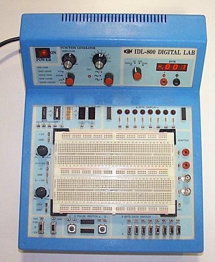
CS4141 IDL Notes. I. Quick Overview of IDL Prototyping Unit
 CS4141 IDL Notes IDL-800 Prototyping System The IDL-800 logic panels are powerful tools for any logic designer. They enable a wide range of IC s to be used in a breadboard experiment. I. Quick Overview
How Do We Figure Out the Voltages and Currents?
 How Do We Figure Out the Voltages and Currents? Diode Solar Cell Li Bat Volt Conv R In this set of lecture notes we ll develop methods to analyze circuits. M. Horowitz, J. Plummer, R. Howe 2 Useless Box
Infrared Add-On Module for Line Following Robot
 1 Infrared Add-On Module for Line Following Robot January 3, 2015 Jeffrey La Favre The infrared add-on module allows multiple line following robots to operate on the same track by preventing collisions
Gateway Profile 4 service guide
 Gateway Profile 4 service guide Customizing Troubleshooting Contents Replacing Components in Your Gateway Profile 4.................. 1 About this guide.....................................................
A4988 Stepper Motor Driver Carrier with Voltage Regulators
 1 of 6 12/2/2011 6:37 PM A4988 Stepper Motor Driver Carrier with Voltage Regulators Pololu item #: 1183 26 in stock Price break Unit price (US$) 1 19.95 10 17.95 100 13.97 Quantity: backorders allowed
Electronic Coin Toss
 1 Electronic Coin Toss Why this circuit? This circuit was not designed for people who can make up their mind nor have a coin to use for a heads or tail coin toss. This circuit can also be used to ask it
Assembling the Printed Circuit Board for the EDE1200 Robot
 This board receives instructions from either a CBL2, a LabPro or (with an adapter cable) an original CBL. The board has two 595 shift registers (each providing 8 bits of on-board memory) and two EDE1200
Replacement Instructions
 imac G5 Inverter, 20-inch Replacement Instructions Follow the instructions in this document carefully. Failure to follow these instructions could damage your equipment and void its warranty. Note: Online
3 pyro output datalogger altimeter with an ATmega 328 microcontroller Kit assembly instructions
 3 pyro output datalogger altimeter with an ATmega 328 microcontroller Kit assembly instructions Version date Author Comments 1.0 29/05/2013 Boris du Reau Initial version Rocket Type Micro-max Model Mid
LEGO Energy Meter. How to Get Started
 LEGO Energy Meter How to Get Started The Energy Meter consists of two parts: the LEGO Energy Display and LEGO Energy Storage. The Energy Storage fits onto the bottom of the Energy Display. To install the
This Datasheet for the IC670GBI002 24VDC BUS INTERFACE UNIT.
 This Datasheet for the IC670GBI002 24VDC BUS INTERFACE UNIT http://www.qualitrol.com/shop/p-14508-ic670gbi002.aspx Provides the wiring diagrams and installation guidelines for this GE Field Control module.
CINTENNA ANTENNA REPAIR GUIDE
 The Cintenna is a great tool when looking to transmit WIRELESS DMX data over obstacles or hard to reach places. Wireless DMX can have its issues when not having a good line of sight between the transmitter
OPERATOR S INSTRUCTION MANUAL DIGITAL MULTIMETER
 OPERATOR S INSTRUCTION MANUAL DIGITAL MULTIMETER SAFETY INFORMATION This multimeter has been designed according to IEC 1010 concerning electronic measuring instruments with an overvoltage category (CATⅡ)
Vector Drive - Troubleshooting Guide
 Haas Technical Documentation Vector Drive - Troubleshooting Guide Scan code to get the latest version of this document Translation Available The Haas Vector drive is the source of power for the spindle
NewScope-7B Operating Manual
 2016 SIMMCONN Labs, LLC All rights reserved NewScope-7B Operating Manual Preliminary May 13, 2017 NewScope-7B Operating Manual 1 Introduction... 3 1.1 Kit compatibility... 3 2 Initial Inspection... 4 3
This Presentation Will
 Investigating Basic Circuits Pre-Activity Discussion Digital Electronics 2014 Project Lead The Way, Inc. This Presentation Will Introduce you to basic circuits and their symbols. Introduce you to components
To connect the AC adapter:
 Replacing the AC Adapter Replacing the AC Adapter 3 Plug the power cord into a wall outlet. The power indicator turns on. To connect the AC adapter: Connect the power cord to the AC adapter. Power indicator
E40M. Solving Circuits using Nodal Analysis and EveryCircuit TM. M. Horowitz, J. Plummer, R. Howe 1
 E40M Solving Circuits using Nodal Analysis and EveryCircuit TM M. Horowitz, J. Plummer, R. Howe 1 How Do We Figure Out the Voltages and Currents? Diode Solar Cell Li Bat Volt Conv R In this set of lecture
A4988 Stepper Motor Driver Carrier
 A4988 Stepper Motor Driver Carrier A4983/A4988 stepper motor driver carrier with dimensions. Overview This product is a carrier board or breakout board for Allegro s A4988 DMOS Microstepping Driver with
Universal Keying Adapter 3+
 Universal Keying Adapter 3+ The Universal Keying Adapter Version 3+ kit will allow you to key nearly any transmitter or transceiver with a straight key, electronic keyer, computer serial or parallel port
A4988 Stepper Motor Driver Carrier, Black Edition
 A4988 Stepper Motor Driver Carrier, Black Edition A4988 stepper motor driver carrier, Black Edition, bottom view with dimensions. Overview This product is a carrier board or breakout board for Allegro
Arduino 05: Digital I/O. Jeffrey A. Meunier University of Connecticut
 Arduino 05: Digital I/O Jeffrey A. Meunier jeffm@engr.uconn.edu University of Connecticut About: How to use this document I designed this tutorial to be tall and narrow so that you can read it on one side
Construction Construction Instructions
 Semi-Virtual Diskette SVD Construction Construction Instructions PCB version 2.0 September 2004 Eric J. Rothfus Table of Contents Table of Contents... i Parts List...1 Construction Overview...5 PCB Construction...
PCI bit Digital Input/ Output Card for PCI Bus. User s Manual
 PCI-1751 48-bit Digital Input/ Output Card for PCI Bus User s Manual Copyright This documentation and the software included with this product are copyrighted 1998 by Advantech Co., Ltd. All rights are
ARRL ETP Solder Hour Clock Kit Construction Manual
 ARRL ETP Solder 101 24-Hour Clock Kit Construction Manual Do a complete parts check cross checking the individual parts against the parts list. Pay particular attention to the color code for the resistors:
9 Output Devices: Buzzers
 9 Output Devices: Buzzers Project In this project, you will learn how to connect and control LEDs (Light Emitting Diode) and a buzzer with the Raspberry Pi. Components In addition to your Raspberry Pi,
SPECIAL INSTRUCTIONS FOR CAPACITORS COMPACT GENERATORS
 SPECIAL INSTRUCTIONS FOR CAPACITORS COMPACT GENERATORS (WITH CAPACITOR CHARGER BOARD A3517-02) The process depends on Generator and System configuration. This document applies to installation of Capacitors
How To: Replace the ZX Spectrum 48 ROM with an EPROM By: Marcelo (inspired by an article in spanish Microhobby #79, p22)
") How To: Replace the ZX Spectrum 48 ROM with an EPROM By: Marcelo (inspired by an article in spanish Microhobby #79, p22) Why: First off, why on earth would one want to do such a thing? Well, there are
How To: Replace the ZX Spectrum 48 ROM with an EPROM By: Marcelo (inspired by an article in spanish Microhobby #79, p22) Why: First off, why on earth would one want to do such a thing? Well, there are
DEV-1 HamStack Development Board
 Sierra Radio Systems DEV-1 HamStack Development Board Reference Manual Version 1.0 Contents Introduction Hardware Compiler overview Program structure Code examples Sample projects For more information,
USER S MANUAL VER.1. C10D- PARALLEL PORT INTERFACE CARD BOARD Rev. 1
 USER S MANUAL VER.1 C10D- PARALLEL PORT INTERFACE CARD BOARD Rev. 1 MARCH 2018 User s Manual Page i USER'S MANUAL TABLE OF CONTENTS Contents Page # 1.0 OVERVIEW... iii 2.0 FEATURES... iii 3.0 SPECIFICATIONS...
EL Wire sequencer / power supply PART NO
 EL Wire sequencer / power supply PART NO. 2206213 The EL Wire sequencer is a EL wire power supply capable of powering 50 plus feet of 2.6mm El Wire and 8 ports controlled by a BS2sx. A menu driven command
RC Tractor Guy Controller V2.1 Assembly Guide
 RC Tractor Guy Controller V. Assembly Guide Features 0 Push button inputs Dual axis thumb sticks with built-in push button Rotary encoders with built-in push button MCU Socket to suit Meduino Mega 560
Pololu 12V Step-Up/Step-Down Voltage Regulator S10V2F12
 Pololu 12V Step-Up/Step-Down Voltage Regulator S10V2F12 Overview The Pololu step-up/step-down voltage regulator S10V2F12 is a switching regulator (also called a switched-mode power supply (SMPS) or DC-to-DC
PCI-1751U. 48-bit Digital Input/Output Card with Universal PCI Bus. User Manual
 PCI-1751U 48-bit Digital Input/Output Card with Universal PCI Bus User Manual Copyright This documentation and the software included with this product are copyrighted 2006 by Advantech Co., Ltd. All rights
K8099 NIXIE CLOCK. * optional enclosure TKOK19 (black) - TKOK17 (white) ** optional plexiglass enlcosure B8099 ILLUSTRATED ASSEMBLY MANUAL
 - TKOK17 (white) ** optional plexiglass enlcosure B8099 ILLUSTRATED ASSEMBLY MANUAL") Total solder points: 230 + 74 Difficulty level: beginner 1 2 3 4 5 advanced NIXIE CLOCK K8099 ** * A unique combination of both vintage and modern electronics ILLUSTRATED ASSEMBLY MANUAL H8099IP-1 * optional
Total solder points: 230 + 74 Difficulty level: beginner 1 2 3 4 5 advanced NIXIE CLOCK K8099 ** * A unique combination of both vintage and modern electronics ILLUSTRATED ASSEMBLY MANUAL H8099IP-1 * optional
Electronics & Control
 Engineering Science Electronics & Control Logic Page 2 Introduction Electronic circuits can be use to control a huge variety of systems but in each case there are IN- PUTS, PROCESSES and OUTPUTS. In this
Copyright 2011 R.S.R. Electronics, Inc. All rights reserved. 04/11. Ver. 1.0web
 For XILINX WebPack Copyright 2011 R.S.R. Electronics, Inc. All rights reserved. 04/11 Ver. 1.0web 1 Table of Contents 1.0 INTRODUCTION...3 2.0 GENERAL DESCRIPTION...5 3.0 BRIEF DESCRIPTION Of PLDT-3 BOARD...6
EECS 140 Laboratory Exercise 4 3-to-11 Counter Implementation
 EECS 140 Laboratory Exercise 4 3-to-11 Counter Implementation 1. Objectives A. To apply knowledge of combinatorial design. B. Gain expertise in designing and building a simple combinatorial circuit This
Huawei Ascend P6-U06 Screen/LCD Display Replacement
 Huawei Ascend P6-U06 Screen/LCD Display Replacement Replace the Huawei Ascend P6-U06's screen and LCD display. Written By: Zachary Rose ifixit CC BY-NC-SA www.ifixit.com Page 1 of 17 INTRODUCTION Replace
Morse Code Practice Oscillator
 Features Description Keyer speed range: Limited only by keying source True Sine wave tone output Tone Volume Control Tone Frequency Control Internal Speaker 1/8 External Speaker/Headphone Jack RCA Key
Upgrading and Servicing Guide
 Upgrading and Servicing Guide The only warranties for Hewlett-Packard products and services are set forth in the express statements accompanying such products and services. Nothing herein should be construed
Standard Logic Chips and National Instruments ELVIS Breadboarding for Combinational Logic Circuits
 ECE380 Digital Logic: Design Activity #4 Standard Logic Chips and National Instruments ELVIS Breadboarding for Combinational Logic Circuits INTRODUCTION In Design Activity #4 you will use the National
LCMM024: DRV8825 Stepper Motor Driver Carrier,
 LCMM024: DRV8825 Stepper Motor Driver Carrier, High Current The DRV8825 stepper motor driver carrier is a breakout board for TI s DRV8825 microstepping bipolar stepper motor driver. The module has a pinout
imac Intel 27" EMC 2639 Hard Drive
 imac Intel 27" EMC 2639 Hard Drive Replacement Replace the Hard Drive in your imac Intel 27" EMC 2639. Written By: Walter Galan ifixit CC BY-NC-SA www.ifixit.com Page 1 of 26 INTRODUCTION Replacing the
Advanced Lantern 1.0 Kit. Introduction to the Advanced Lantern 1.0 Kit
 Advanced LED Lantern 1.0 Instruction Manual Eastern Voltage Research, LLC Introduction to the Advanced Lantern 1.0 Kit Thank you for purchasing the Advanced Lantern 1.0 Kit. This kit is an advanced microprocessor
Building the FlipChip Tester
 Building the FlipChip Tester 1. Assembly of the Core Board You will need a fine low-wattage soldering iron and a Voltmeter. Take your time to solder the components on the Core Board. Better to spend a
Upgrading and Servicing Guide
 Upgrading and Servicing Guide The information in this document is subject to change without notice. Hewlett-Packard Company makes no warranty of any kind with regard to this material, including, but not
PCL channel Isolated Digital I/O Card
 PCL-730 32-channel Isolated Digital I/O Card Copyright This documentation is copyrighted 1996 by Advantech Co., Ltd. All rights are reserved. Advantech Co., Ltd. reserves the right to make improvements
PowerFlex 700L Liquid-to-Liquid Heat Exchanger Control Board Replacement
 Installation Instructions PowerFlex 700L Liquid-to-Liquid Heat Exchanger Replacement ATTENTION: To avoid an electric shock hazard and prevent thermal damage, ensure that all power to the drive power module
Pacific Antenna Easy TR Switch Kit
 Pacific Antenna Easy TR Switch Kit Kit Description The Easy TR Switch is an RF sensing circuit with a double pole double throw relay that can be used to automatically switch an antenna between a separate
UF-3701 Power Board Construction Guide
 Page 1/5 Soldering and Part Placement See the Chapter 3 of the MIT 6270 Manual for information on electronic assembly, including soldering techniques and component mounting. Construction Information All
Alesis MMT8 16x Memory Expansion Modification (Black model MMT8 s) Equipment. Components required. Other bits:
 Equipment. Components required. Other bits:") Alesis MMT8 16x Memory Expansion Modification (Black model MMT8 s) by Graham Meredith, 006 Revised 15 th January 009 gmeredith1@yahoo.com.au This modification expands the memory of the Alesis MMT8 to 16x
Alesis MMT8 16x Memory Expansion Modification (Black model MMT8 s) by Graham Meredith, 006 Revised 15 th January 009 gmeredith1@yahoo.com.au This modification expands the memory of the Alesis MMT8 to 16x
GR8NET sound line decoupling
 Feb 03, 2016 Rev: Feb 05, 2016 Severity: Critical Eugeny Brychkov, RU GR8NET sound line decoupling Purpose. To ensure safe operation of the GR8NET adapter in terms of its sound output and other adapters
GV3000/SE AC Drive ControlNet Network Communication Option Board M/N 2CN3000
 GV3000/SE AC Drive ControlNet Network Communication Option Board M/N 2CN3000 Instruction Manual D2-3390-2 The information in this manual is subject to change without notice. Throughout this manual, the
The mystem Project Board Quick Start
 The mystem Project Board Quick Start This activity will introduce you to the basic functions of the mystem Project Board to get you started. Introduction to the mystem The mystem Project Board is designed
Installation/assembly manual for DCC/Power shield
 Installation/assembly manual for DCC/Power shield The DCC circuit consists of the following components: R1/R6 R2/R3 R4/R5 D1 C2 2 kω resistor ½ Watt (colour code Red/Black/Black/Brown/Brown) 10 kω resistor
This presentation will..
 Component Identification: Digital Introduction to Logic Gates and Integrated Circuits Digital Electronics 2014 This presentation will.. Introduce transistors, logic gates, integrated circuits (ICs), and
OPERATOR S INSTRUCTION MANUAL DIGITAL MULTIMETER MAS830 MAS830L
 OPERATOR S INSTRUCTION MANUAL MAS830 MAS830L DIGITAL MULTIMETER SAFETY INFORMATION This multimeter has been designed according to IEC -1010 concerning electronic measuring instruments with an overvoltage
RC-210 Repeater Controller Assembly Manual
 Arcom Communications 24035 NE Butteville Rd Aurora, Oregon 97002 (503) 678-6182 arcom@ah6le.net RC-210 Repeater Controller Assembly Manual Hardware Version 3.0 Original Release Date September 13, 2004
PAD ANALOG / DIGITAL TRAINER OPERATOR S MANUAL
 PAD - 234 ANALOG / DIGITAL TRAINER OPERATOR S MANUAL Rev. 7/94 GENERAL OPERATING PROCEDURES 1. This manual should be read thoroughly before engaging in any experimentation. 2. As a general rule, NEVER
LBI MAINTENANCE MANUAL DESKTOP STATION INTERCONNECT BOARD 188D5418G1 DESCRIPTION TABLE OF CONTENTS. Page
 MAINTENANCE MANUAL INTERCONNECT BOARD 88D548G TABLE OF CONTENTS DESCRIPTION................................................ Front Cover CIRCUIT DESCRIPTION........................................... TRANSMIT
2 in 1 LAN Tester and Multimeter Model:
 2 in 1 LAN Tester and Multimeter Model: 72-8495 1 IMPORTANT SAFETY INFORMATION Please read these instructions carefully before use and retain for future reference. This instrument is designed and manufactured
Written By: Charlie Mohr
 NEC LCD1770NX Capacitor Replacement Replacement of a capacitor on the power supply circuit board. Written By: Charlie Mohr ifixit CC BY-NC-SA www.ifixit.com Page 1 of 14 INTRODUCTION There are many capacitors
CRESCENDO /7200 G3. Quick Start Guide for Crescendo /7200. Processor Upgrade Card for Power Macintosh 7200/8200 Computers
 CRESCENDO /7200 G3 Processor Upgrade Card for Power Macintosh 7200/8200 Computers Quick Start Guide for Crescendo /7200 System Compatibility At this printing, processor upgrade cards are compatible with
ENCORE /ST G4 DUET. Dual Processor Upgrade Card for Power Mac G4 AGP Graphics. Quick Start Guide for Encore/ST G4 Duet
 ENCORE /ST G4 DUET Dual Processor Upgrade Card for Power Mac G4 AGP Graphics Quick Start Guide for Encore/ST G4 Duet Power Mac and Operating System Compatibility This Encore/ST G4 Duet processor upgrade
INSTALLATION INSTRUCTIONS
 TT-40 9/0 INSTALLATION INSTRUCTIONS Original Issue Date: 9/0 Model: Automatic Transfer Switches Equipped with the Programmable Controller Market: ATS Subject: External Battery Supply Module Kit GM69-KP
The GENIE Light Kit is ideal for introducing simple lighting projects, such as an electronic die, a wearable badge or a night-time warning system.
 Introduction 1 Welcome to the GENIE microcontroller system! The GENIE Light Kit is ideal for introducing simple lighting projects, such as an electronic die, a wearable badge or a night-time warning system.
Upgrading and Servicing Guide
 Upgrading and Servicing Guide The only warranties for Hewlett-Packard products and services are set forth in the express statements accompanying such products and services. Nothing herein should be construed
dual bipolar voltage controlled step sequencer DIY ASSEMBLY MANUAL v1.03
 dual bipolar voltage controlled step sequencer DIY ASSEMBLY MANUAL v1.03 Contents Contents... 2 Introduction... 3 Part Sourcing Notes for Non Kit Builders... 3 Eurorack Kit Assembly... 4 Resistors and
EQ573 Assembly guide. EQ573 Assembly guide Main board 1. Diodes. 2. Resistors (1) 3. Test pins. 4. Ceramic capacitors.
 3. Test pins. 4. Ceramic capacitors.") EQ573 Assembly guide Safety warning The kits are main powered and use potentially lethal voltages. Under no circumstance should someone undertake the realisation of a kit unless he has full knowledge about
EQ573 Assembly guide Safety warning The kits are main powered and use potentially lethal voltages. Under no circumstance should someone undertake the realisation of a kit unless he has full knowledge about
AT42QT1010 Capacitive Touch Breakout Hookup Guide
 Page 1 of 7 AT42QT1010 Capacitive Touch Breakout Hookup Guide Introduction If you need to add user input without using a button, then a capacitive touch interface might be the answer. The AT42QT1010 Capacitive
PCM ch Isolated Digital I/O Module. User Manual
 PCM-3730 32-ch Isolated Digital I/O Module User Manual Copyright The documentation and the software included with this product are copyrighted 2005 by Advantech Co., Ltd. All rights are reserved. Advantech
PARTS LIST 1 x PC Board 36 x 5mm Red LED 36 x 12mm LED Standoff 36 x NPN Transistor 36 x 10kΩ Resistor OTHER PARTS YOU MAY NEED
 PARTS LIST 1 x PC Board 36 x 5mm Red LED 36 x 12mm LED Standoff 36 x NPN Transistor 36 x 150Ω Resistor 36 x 10kΩ Resistor 17 x Mini Toggle on-off 8 x Mini Toggle (on)-off-(on) 1 x 470Ω Resistor 1 x 47µF
Chapter 19. Floppy Disk Controller Discussion. Floppy Disk Controller 127
 Floppy Disk Controller 127 Chapter 19 Floppy Disk Controller 19-1. Discussion Without some "mass storage" device such as a floppy disk, even the largest computer would still be just a toy. The SK68K can