Options for ABB drives. User s manual FPTC-02 ATEX-certified thermistor protection module, Ex II (2) GD (option +L537+Q971) for ACS880 drives
|
|
|
- Briana O’Brien’
- 5 years ago
- Views:
Transcription
 GD (option +L537+Q971) for")
1 Options for ABB drives User s manual FPTC-02 ATEX-certified thermistor protection module, Ex II (2) GD (option +L537+Q971) for ACS880 drives
2 List of related manuals Drive hardware manuals Code (EN) ACS hardware manual 3AUA ACS hardware manual 3AUA ACS drive module packages hardware manual 3AUA ACS hardware manual 3AXD ACS hardware manual 3AXD ACS and -34 hardware manual 3AXD ACS880-04XT (500 to 1200 kw) hardware manual 3AXD ACS880-04F drive modules hardware manual 3AXD ACS880-M04 hardware manual 3AXD ACS (45 to 630 kw) hardware manual 3AUA ACS (560 to 2800 kw) hardware manual 3AUA ACS (160 to 3200 kw) hardware manual 3AXD ACS ( kw) hardware manual 3AXD ACS (160 to 3200 kw) hardware manual 3AXD ACS ( kw) hardware manual 3AXD ACS inverter modules hardware manual 3AUA ACS LC inverter modules hardware manual 3AXD ACS inverter units hardware manual 3AUA Drive firmware manuals ACS880 primary control program firmware manual 3AUA Option manuals and guides FSO-12 safety functions module user's manual 3AXD FSO-21 safety functions module user s manual 3AXD FSE-31 pulse encoder interface module user s manual 3AXD FPTC-02 ATEX-certified thermistor protection module, 3AXD Ex II (2) GD (option +L537 +Q971) user s manual Manuals and quick guides for I/O extension modules, fieldbus adapters, etc. Drive PC tool manuals Drive composer start-up and maintenance PC tool 3AUA user's manual General safety guides Functional safety; Technical guide No. 10 3AUA Safety and functional safety; A general guide 1SFC001008B0201 ABB Safety information and solutions Potentially explosive atmospheres. The basics you need 3AUA to know about motors and drives You can find manuals and other product documents in PDF format on the Internet. See section Document library on the Internet on the inside of the back cover. For manuals not available in the Document library, contact your local ABB representative.


3 User s manual FPTC-02 ATEX-certified thermistor protection module, Ex II (2) GD (option +L537 +Q971) for ACS880 drives Table of contents 1. Safety 5. Mechanical installation 6. Electrical installation 8. Start-up and acceptance test 3AXD Rev C EN EFFECTIVE: ABB Oy All Rights Reserved.
4
5 Table of contents Table of contents 5 1. Safety Contents this chapter Use of warnings Safety in installation and maintenance Other warnings Introduction to the manual Contents of this chapter Applicability Compatibility Target audience Contents of the manual Related documents Terms and abbreviations Exclusion of liability Hardware description Contents of this chapter Product overview Operation basics XFLT input (Fault) XWRN input (Warning) Markings FPTC-02 module Type designation label ATEX markings Drive Option +Q SMT function Option description and instructions Contents of this chapter
6 6 Table of contents ACS880-01/04/04XT/04F/M04/11/31/14/34/104 drives and modules Cabinet-built drives The ATEX-certified Safe disconnection function Resetting the safety function Indications of the safety function Switching frequency limitation Fault reaction function FPTC-02 module STO function in the drive/inverter modules FSO module Mechanical installation Contents of this chapter Necessary tools and instructions Unpacking and examining the delivery Installing the module Electrical installation Contents of this chapter Warnings Necessary tools and instructions General cabling instructions Terminal designations Wiring Wiring example Wiring example Wiring example Wiring example Wiring example Parameter settings Contents of this chapter Drive/inverter Other recommended settings FSO module General parameters

7 Table of contents 7 Parameters related to the STO function Parameters related to the SSE function FSE module and safety pulse encoder parameters Additional notes Mechanical brake control Start-up and acceptance test Contents of this chapter Before you start Acceptance test Fault tracing Contents of this chapter Reporting failures FPTC-02 module replacement Fault and warning messages LEDs Maintenance Contents of this chapter Maintenance Proof test interval Competence Residual risk Intentional misuse Decommissioning Technical data Contents of this chapter Dimension drawing Isolation areas Connections Motor thermistor connection STO output connection Ambient conditions Safety data Safety block diagrams

8 8 Table of contents Response times Relevant failure modes General rules, notes and definitions Validation of the safety functions Validation procedure Acceptance test reports Competence Ambient conditions Reporting problems and failures related to safety functions 87 Related standards and directives Compliance with the European Machinery Directive Compliance with the European ATEX Directive ATEX certificate TÜV Nord certificate Further information Product and service inquiries Product training Providing feedback on ABB manuals Document library on the Internet
9 Safety 9 1 Safety Contents this chapter The chapter contains the warning symbols used in this manual and the safety instructions which you must obey when you install or connect an option module to a drive. If you ignore the safety instructions, injury, death or damage can occur. Read this chapter before you start the installation. Use of warnings Warnings tell you about conditions which can cause injury or death, or damage to the equipment. They also tell you how to prevent the danger. The manual uses these warning symbols: Electricity warning tells you about hazards from electricity which can cause injury or death, or damage to the equipment.
10 10 Safety General warning tells you about conditions, other than those caused by electricity, which can cause injury or death, or damage to the equipment. Safety in installation and maintenance These instructions are for all who install or connect an option module to a drive and need to open its front cover or door to do the work. WARNING! Obey these instructions. If you ignore them, injury or death, or damage to the equipment can occur. If you are not a qualified electrician, do not do installation or maintenance work. Disconnect the drive from all possible power sources. After you have disconnected the drive, always wait for 5 minutes to let the intermediate circuit capacitors discharge before you continue. Disconnect all dangerous voltages connected to other connectors or parts in reach. For example, it is possible that 230 V AC is connected from outside to a relay output of the drive. Always use a multimeter to make sure that there are no parts under voltage in reach. The impedance of the multimeter must be at least 1 Mohm.
 feature of ACS880 drives cannot prevent the intermediate DC current from flowing through, and heating up, the motor in case a short circuit occurs in the output stage of the")
11 Safety 11 Other warnings WARNING! The Safe torque off (STO) feature of ACS880 drives cannot prevent the intermediate DC current from flowing through, and heating up, the motor in case a short circuit occurs in the output stage of the drive. The supplier must take this into account when planning the protection of the installation. WARNING! ACS880 cabinet-built drives: Never connect, test or measure a drive based on the diagrams of this manual. Each delivery is unique. Before starting the work on the electric circuits of a drive, always refer to the deliveryspecific circuit diagrams.

12 12 Safety
13 Introduction to the manual 13 2 Introduction to the manual Contents of this chapter This chapter gives basic information on the manual. Applicability This manual applies to the FPTC-02 module and to the Safe motor temperature safety function which uses the FPTC-02 module (option +L537+Q971).
14 14 Introduction to the manual Compatibility The FPTC-02 module is compatible with: ACS880-01/04/04XT/04F/M04/11/31/14/34/104 drives and modules which have a serial number starting with 1, 7 or 8 ACS880-07/17/37 cabinet-built single drives ACS880 multidrives FSO-12 safety functions module FSO-21 safety functions module ACS880 primary control program version 2.10 or later Other control programs: Check the compatibility with your local ABB representative. ACS880 liquid-cooled drives, modules and multidrives: Check the compatibility with your local ABB representative.
15 Introduction to the manual 15 Target audience This manual is intended for people who plan the installation, install, start up, use and service the option module. Before you do work on the module, read this manual and the applicable drive manual that contains the hardware and safety instructions for the product in question. You are expected to know the fundamentals of electricity, wiring, electrical components and electrical schematic symbols and ATEX/Ex regulations. The manual is written for readers worldwide. Both SI and imperial units are shown.
16 16 Introduction to the manual Contents of the manual The manual consists of these chapters: Safety contains the safety instructions which you must obey when you install the module. Introduction to the manual (this chapter) introduces the manual. Hardware description gives a short description of the module. Option description and instructions describes the Safe motor temperature function implemented with the module and the drive Safe torque off function. Mechanical installation contains a delivery checklist and instructions on installing the module. Electrical installation contains instructions on wiring the module. Parameter settings lists the parameters related to the safety function. Start-up and acceptance test contains instructions on starting up the module and the acceptance test for the Safe motor temperature function. Fault tracing shows how to trace faults with the status LEDs on the module. Technical data contains the technical data of the module, the safety data and relevant certificates and Declarations of Conformity. Related documents Product manuals, see the inside of the front cover. ACS880 cabinet-built drives: Circuit diagrams delivered with the drive.
17 Terms and abbreviations Introduction to the manual 17 Term/abbreviation Description ATEX Directives 2014/34/EU (94/9/EC) and 1999/92/EC are commonly referred to as the ATEX directives (from Atmosphères Explosibles ) Cat. Category. Classification of the safety-related parts of a control system in respect of their resistance to faults and their subsequent behavior in the fault condition, and which is achieved by the structural arrangement of the parts, fault detection and/or by their reliability. The categories are: B, 1, 2, 3 and 4. CCF Common cause failure (EN ISO ) DC Diagnostic coverage (%) (EN ISO ) DI Digital input DO Digital output DTC Direct torque control EMC Electromagnetic compatibility Ex An IEC term used in the context of explosive atmospheres Ex d Type of protection, flameproof enclosures (EN/IEC ) Ex e Type of protection, increased safety (EN :2007 and IEC :2006), to be replaced with Ex eb Ex eb, Ex ec Types of protection, increased safety (IEC :2015) Ex motors Motors used in explosive atmospheres Ex na Type of protection, non-sparking enclosures (EN/IEC :2010), to be replaced with Ex ec FEA-03 F-series extension adapter module FPTC-02 ATEX-certified thermistor protection module, Ex II (2) GD FSE-31 Pulse encoder interface module which can be used in safety applications FSO Safety functions module (FSO-12 or FSO-21)
18 18 Introduction to the manual Term/abbreviation Description FSO-12 Safety functions module which does not support the use of safety encoders FSO-21 Safety functions module which supports the FSE-31 module and the use of safety encoders GND Ground HFT Hardware fault tolerance. (EN/IEC 62061, IEC 61508) MTTF D Mean time to dangerous failure: (The total number of life units) / (the number of dangerous, undetected failures) during a particular measurement interval under stated conditions (EN ISO ) PELV Protected extra-low voltage (IEC ) PFD avg Average probability of dangerous failure on demand (IEC 61508, EN/IEC , EN/IEC 62061) PFH Average frequency of dangerous failures per hour [1/h] (IEC 61508, EN/IEC , EN/IEC 62061) PL Performance level (levels are: a, b, c, d and e). Corresponds to SIL. (EN ISO ) PTC Positive temperature coefficient SAR Safe acceleration range. In the FSO module, there are two sets of SAR parameters (SAR0 and SAR1) that are used to define and/or monitor the deceleration ramp in safety functions. Safety system Whole safety system including, for example, human interface, FPTC-02 module, FSO module, drive and sensors. SBC Safe brake control. A safety function in the FSO module. SC Systematic capability (IEC 61508) SFF Safe failure fraction (%) (IEC 61508). SIL Safety integrity level (levels are: 1, 2, 3, and 4). Corresponds to PL. (IEC 61508) SILCL SIL claim limit. Maximum SIL that can be claimed for a safety function or subsystem. (EN/IEC 62061)
19 Term/abbreviation Description Introduction to the manual 19 SMT Safe motor temperature. (EN/IEC ) SS1 Safe stop 1 (EN/IEC ). A safety function in the FSO module. SSE Safe stop emergency. A safety function in the FSO module. STO Safe torque off. (EN/IEC ) In this manual, this term is used in two different contexts: the STO circuit in the drive (the drive STO function) the STO safety function in the FSO module. Stop category 0 Uncontrolled stop (EN/IEC ) Stop category 1 Controlled stop (EN/IEC ) T1 Proof test interval (IEC 61508). T1 is a parameter used to define the probabilistic failure rate (PFH or PFD avg ) for the safety function or subsystem. Performing a proof test at a maximum interval of T1 is required to keep the SIL capability valid. The same interval must be followed to keep the PL capability (EN ISO 13849) valid. Note that any T1 values stated cannot be regarded as a guarantee or warranty. See also section Proof test interval on page 74. XFLT PTC input for the Safe motor temperature (SMT) fault in the FPTC module XWRN PTC input for a motor temperature warning in the FPTC module Zone Potentially explosive atmosphere. Hazardous areas are divided into zones, according to the degree of hazard. The degree of hazard is defined according to the probability of the occurrence of explosive atmospheres.
20 20 Introduction to the manual Exclusion of liability ABB is not responsible for the implementation, verification and validation of the overall safety system. It is the responsibility of the end user (or other party) who is responsible for the overall system, system safety and compliance with ATEX/Ex regulations. The end user (or other responsible party) must make sure that the entire implementation complies with all relevant standards, directives and local electrical code, and that the system is tested, verified and validated correctly.
21 Hardware description 21 3 Hardware description Contents of this chapter This chapter gives a short description of the module. Product overview The FPTC-02 ATEX-certified thermistor protection module, Ex II (2) GD is Type Examined as a protective device within the scope of the European ATEX Product Directive. This enables the use of the module in temperature protection of motors in explosive atmospheres (Ex motors). The FPTC-02 module implements the Safe motor temperature (SMT) safety function as defined in EN/IEC :2007. Inside the module, there is reinforced insulation between the motor thermistor connection and the other terminals of the module. The insulation forms a reliable protective separation between the motor main circuit and the drive control circuits. Therefore, the drive control board is PELV compatible also when the FPTC-02 module and a thermistor protection circuit are installed. For more information on isolation areas of the module and insulation between them, see section Isolation areas on page 79.
22 22 Hardware description Operation basics The module includes two PTC sensor inputs: XFLT executes the ATEX-certified SIL/PL capable SMT safety function by activating the drive Safe torque off (STO) function. This input is a safety-related input and can be used for protection function purposes. XWRN generates a warning to the drive. This is not a safetyrelated input and can only be used for indication purposes. XFLT input (Fault) When the motor temperature rises above the PTC sensor limit temperature, the sensor resistance increases sharply. This indicates overtemperature to the FPTC-02 module. The FPTC-02 module executes the SMT function by switching off the drive Safe torque off (STO) circuit. This activates the drive STO function. The STO function disables the control voltage of the power semiconductors of the drive output stage. This prevents the drive from generating the torque required to rotate the motor. If the motor is running when the STO function is activated, it coasts to a stop. Note: If you want to disable the SMT function, you have to connect a resistor (100 ohm...1 kohm 1/4 W wire-wound) in the XFLT input instead of a PTC sensor. XWRN input (Warning) When the motor temperature rises above the PTC sensor limit temperature, the sensor resistance increases sharply. The module sends a warning indication to the drive. For the resistance limits and other technical details of the FPTC-02 module, see chapter Technical data.
23 Hardware description 23 Layout XWRN XSTO2 XFLT XSTO1 2 1
24 24 Hardware description Item Description 1 Retaining clips 2 Lock 3 Diagnostics LEDs (see section LEDs on page 72) 4 Mounting screw XWRN 2-pin detachable terminal block for PTC warning (non-safety related) XFLT 2-pin detachable terminal block for PTC fault (safety related) XSTO1 2-pin detachable terminal block for STO output 1 XSTO2 2-pin detachable terminal block for STO output 2

25 Hardware description 25 Markings FPTC-02 module Type designation label The type designation label is attached on the back side of the FPTC-02 module. An example label and description of the label contents are shown below Item Description 1 Type 2 Serial number of format RYWWSSSS, where R: Component revision: A, B, C, Y: Last digit of the manufacturing year: 4, 5, for 2014, 2015 WW: Manufacturing week: 01, 02, for week 1, week 2, SSSS: Integer starting every week from ABB MRP code of the module 4 Combined ABB MRP code, serial number and manufacturing location 5 RoHS mark
26 26 Hardware description ATEX markings The markings on the module signify ATEX classification of the FPTC-02 module Item Description 1 The European Commission mark for Ex products. 2 Equipment group II: Product for surface industry (other than mining applications). 3 Category 2 equipment. Brackets indicate that the module must be installed outside the potentially explosive atmosphere. 4 Certified for use in explosive atmospheres caused by: G = gases, vapors or mists, D = dust.
27 Hardware description 27 Drive Option +Q971 When the FPTC-02 module is ordered as a factory-installed option, an additional sticker is sometimes attached to the drive/module to signify ATEX classification of the drive Safe disconnection function (+Q971) of the drive/module (see page 31). This sticker and the ATEX certification reference are not mandatory with the FPTC-02 module Item Description 1 CE marking with Notified Body identification: The manufacturer declares that the product conforms with European Council ATEX Directive 2014/34/EU (previously 94/9/EC). Notified Body: VTT Expert Services Ltd. 2 The European Commission mark for Ex products. 3 Equipment group II: Product for surface industry (other than mining applications). 4 Category 2 equipment: Brackets indicate that the drive (or inverter module) must be installed outside the potentially explosive atmosphere. 5 Certified for use in explosive atmospheres caused by: G = gases, vapors or mists, D = dust. 6 Certificate reference. The option code +Q971 is included in the type designation label of the drive. In cabinet-installed drives, this is on the cabinet door. In cabinet-installed drives, there is no separate ATEX classification label for the Safe disconnection function.
28 28 Hardware description SMT function When the FPTC-02 module is delivered as an add-on kit, the package contains a sticker to signify ATEX classification of the Safe motor temperature (SMT) function. The user must attach this sticker to the drive/inverter module next to the type designation label. In the factory-installed options, this sticker is already attached to the drive/inverter module at the factory. In the cabinet-built drives, this sticker is attached on the cabinet door at the factory Item Description 1 CE marking with Notified Body identification: The manufacturer declares that the product conforms with European Council ATEX Directive 2014/34/EU (previously 94/9/EC). Notified Body: VTT Expert Services Ltd. 2 The European Commission mark for Ex products. 3 Equipment group II: Product for surface industry (other than mining applications). 4 Category 2 equipment: Brackets indicate that the drive (or inverter module) must be installed outside the potentially explosive atmosphere. 5 Certified for use in explosive atmospheres caused by: G = gases, vapors or mists, D = dust. 6 Certificate reference.
29 Option description and instructions 29 4 Option description and instructions Contents of this chapter This chapter describes the Safe motor temperature function implemented with the FPTC-02 module and the drive Safe torque off function and gives instructions for the user. Overview To implement the Safe motor temperature (SMT) function, you can connect the FPTC-02 module directly to the drive Safe torque off (STO) circuit, or you can use it together with an FSO module. The FSO safety functions module (FSO-12 or FSO-21) is an optional device used with the ACS880 drives to implement safety functions. When installed, it reserves the standard STO connection of the drive. In this case, safety function in the FSO module can activate the STO function of the drive (that is, open the drive STO circuit). Note: The Safe motor temperature function is motor-specific also in the ACS880 multidrives where several motors are connected to the drive.
30 30 Option description and instructions ACS880-01/04/04XT/04F/M04/11/31/14/34/104 drives and modules The module is available as a factory-installed option (+L537+Q971) or as an add-on kit for drives and modules. For the kit, the user: makes sure that serial number of the drive/module starts with 1, 7 or 8 (refers to certain manufacturing locations) attaches the ATEX label for the SMT function (a sticker is included in the module package, see page 28) to the drive/inverter module to ensure the ATEX compliance of the safety circuit, installs the option module to an option slot of the drive control unit, and sets the related drive parameters connects the PTC temperature sensors of the motor to the PTC inputs of the option module, and connects the drive STO terminals to the STO output of the option module (or to the FSO module and configures the FSO module to perform the STO function). Cabinet-built drives For cabinet-built ACS880-07/17/37 single drives and ACS880 multidrives, the module is available as factory-installed options: +L537+Q971 +L537+Q971+Q973 (with the FSO-12 module) +L537+Q971+Q972 (with the FSO-21 module) +L537+Q971+Q972+L521 (with the FSO-21 and FSE-31 modules). The user connects the PTC temperature sensors of the motor to the PTC inputs of the module.
31 Option description and instructions 31 The ATEX-certified Safe disconnection function The ATEX-certified Safe motor temperature function described in this manual requires that its Safe torque off function (STO) is certified for use as a Safe disconnection function to protect equipment in potentially explosive atmospheres according to European ATEX Product Directive 2014/34/EU (previously 94/9/EC). For more information on the drive STO function, see the appropriate hardware manual. You can use the FPTC-02 module only when serial number of the drive/module starts with 1, 7 or 8 (refers to certain manufacturing locations). Note: You do not need a separate ATEX certification (and label) for the Safe disconnection function (+Q971), because the ATEX certificate of the SMT function includes also the ATEX-certified Safe torque off function (STO).
32 32 Option description and instructions Resetting the safety function The ATEX/Ex regulations require that the safety function must be reset manually. When the XFLT input detects a motor overtemperature situation, the FPTC-02 module generates a fault to the drive. The user must reset the drive before it is possible to restart the drive. When the XWRN input detects a motor overtemperature situation, the FPTC-02 module generates a warning to the drive. This is not a safety-related function and does not need a reset. When an FSO module is used together with the FPTC-02 module, it is possible that the user must reset the safety function also with a reset button connected to the FSO module. This depends on parameter settings and other safety functions in the FSO module. For more information, see section FSO module on page 55. Note: The reset function of the safety function is not SIL classified.
33 Indications of the safety function Option description and instructions 33 An indication of the safety function can come from several sources: 1. LED indications on the FPTC-02 module: The Fault LED is red when motor temperature is outside the allowed (safe) temperature range (XFLT input). The WARNING LED is red when motor temperature outside the temperature warning range (XWRN input). 2. Safe motor temperature fault (XFLT) or motor temperature warning (XWRN) in the drive. 3. STO indication in the drive: The drive STO indication is active when the SMT safety function has activated the drive STO function. The type of the indication is set with parameter STO indication on the FSO module: The STO LED is green when the safety function has activated the drive STO. 5. STO indication from the FSO module to the drive: The FSO module sends an indication to the drive when the FSO module activates the drive STO. The type of the indication is set with parameter FSOGEN.61. To avoid parallel indications, set the STO indication parameters (31.22 and/or FSOGEN.61) to value None/No indication or Event. See chapter Parameter settings for instructions. Note: The indications of the safety function are not SIL classified.
34 34 Option description and instructions Switching frequency limitation The certificate of the Ex motor requires that you set a minimum limit for the switching frequency of the drive. Make sure that the Ex motor is operated above the minimum switching frequency specified by the motor manufacturer. For ABB Ex motors, use parameter to set the required minimum switching frequency (see page 53). For Ex motors supplied by other motor manufactures, contact the motor manufacturer for the correct value and your local ABB representative for instructions on how to make the parameter setting in the drive.
35 Option description and instructions 35 Fault reaction function FPTC-02 module The FPTC-02 module has a fault reaction function. When the module detects an internal fault or fault in the temperature sensor circuit, it gives a request to the drive control unit to stop modulation and activates the drive STO function. STO function in the drive/inverter modules The STO function in the drive/inverter module has internal fault diagnostics and a fault reaction function which causes a fault trip in case it detects a redundancy fault of STO control signals or any internal failure. See the hardware and firmware manuals of the drive/inverter module. FSO module The fault reaction function of the FSO module trips the drive if it detects a failure. The FSO module activates the STO or Safe stop emergency (SSE) function. This activates the drive STO function. The drive STO function is active until the fault has been repaired. Note: With the FPTC module, the recommended type of the SSE function is Immediate STO, but other safety functions in the FSO module can require that the type is Emergency ramp. With both settings, the FSO module always activates the drive STO function immediately in motor overtemperature situations (SMT function activated). The FSO module goes into the Fail-safe mode. The FSO module LED STATUS/FAULT is red until the fault has been repaired. To exit the Fail-safe mode, remove the cause of the fault and reset the FSO module by switching the power off and on, by pressing the Boot FSO button on the Safety view of Drive composer pro or with drive parameter FSO reboot. For more information, see the drive firmware manual and the FSO module user s manual.
36 36 Option description and instructions
37 Mechanical installation 37 5 Mechanical installation Contents of this chapter This chapter contains a delivery checklist and instructions on installing the module. Necessary tools and instructions Torx screwdriver (T10) For a complete list of tools, see the applicable drive hardware manual. Unpacking and examining the delivery 1. Open the option package. 2. Make sure that the package contains: FPTC-02 module STO cable ATEX label (with the ATEX classification markings) this manual. 3. Make sure that there are no signs of damage.
38 38 Mechanical installation Installing the module WARNING! Obey the safety instructions. See chapter Safety. If you ignore the safety instructions, injury or death can occur. 1. Pull out the lock. 2. Put the module carefully into its position on the drive until the retaining clips lock it into position. 3. Push in the lock. 4. Tighten the screw. Note: The screw tightens the connections and grounds the module. It is necessary for fulfilling the EMC requirements and for proper operation of the module. WARNING! Do not tighten the screw tighter than 0.8 N m. Too high a torque breaks the thread. See the applicable drive manual for further instructions on how to install the module to the drive. Note: Do not install the FPTC-02 module on an FEA-03 F-series extension adapter. The diagnostics of the module requires that you install it directly on the drive control unit.

39 Mechanical installation
40 40 Mechanical installation
41 Electrical installation 41 6 Electrical installation Contents of this chapter This chapter contains instructions on wiring the module. Warnings WARNING! Obey the safety instructions. See chapter Safety. If you ignore the safety instructions injury or death can occur. Make sure that the drive is disconnected from the input power during installation. If the drive is already connected to the input power, wait for 5 minutes after disconnecting the input power. Necessary tools and instructions Screwdriver with a set of suitable bits, cabling tools.
42 42 Electrical installation General cabling instructions 1. For the STO circuit wiring, use the type of cable specified in the appropriate drive or inverter module hardware manual (except when an FSO module or other safety relays are installed in the STO command chain). 2. Wire only the sensor circuit into the potentially explosive atmosphere. 3. The PTC sensor circuit in the Ex Zone must comply with the requirements for the applicable type of protection, such as: Ex d (EN/IEC ), Ex eb (IEC :2015; Ex e in EN :2007 and IEC :2006), Ex ec (IEC :2015; Ex na in EN/IEC :2010). 4. Install the drive (or inverter module), the Safe torque off (STO) circuit, and the protection relay outside the hazardous zone. 5. Route the sensor cables away from the motor cable. 6. We recommend to use a shielded sensor cable to minimize electromagnetic interference from power cables. Note: The drive STO function has a redundant architecture, that is, both STO channels must be used in the safety function implementation. For more information, see the hardware manual. If you do not want to use the XFLT input (Fault), connect a resistor (100 ohm...1 kohm 1/4 W wire-wound) in the XFLT input instead of a PTC sensor. If you do not want to use the XWRN input (Warning), disable the motor temperature warning with a parameter setting (see chapter Parameter settings on page 51).
43 Terminal designations Marking Description XSTO1 STO channel 1 11 In, +24 V DC in for STO 12 Out, +24 V DC out for STO XSTO2 STO channel 2 21 In, +24 V DC in for STO 22 Out, +24 V DC out for STO XFLT PTC FAULT (SMT function) T1 In, V DC T2 Out XWRN PTC WARNING (non-safety related) T3 In, V DC T4 Out Electrical installation 43
44 44 Electrical installation Wiring This section presents five ways to connect the FPTC-02 module to the drive STO terminals. Wiring example 1 (see page 45): The STO outputs of the FPTC-02 module are connected directly to the STO terminals of the drive. ACS880-01/04/04XT/04F/M04/11/31/14/34/104 drives and modules: In the factory-installed option (+L537+Q971), the wiring is done at the factory according to this example. ACS880 cabinet-built drives: In the option +L537+Q971, terminal block [X969] is located between the module and the drive control board (not shown in the figure). See the circuit diagrams delivered with the drive for the actual wiring. Wiring example 2 (see page 46): The STO outputs of the FPTC-02 module are connected to an FSO module, and the STO outputs of the FSO module to the STO terminals of the drive with a twochannel connection. In this case, the FSO module controls the drive STO function. Cabinet-built drives: In the option +L537+Q971+Q973/Q972 (+L521), terminal block [X68] is located between the module and the FSO module (not shown in the figure). See the circuit diagrams delivered with the drive for the actual wiring. Wiring example 3 (see page 47): An external safety relay is connected between the FPTC-02 module and the drive STO inputs with a two-channel connection. Wiring example 4 (see page 48): The STO outputs of the FPTC-02 module are connected directly to the STO terminals of the drive with a one-channel connection. Wiring example 5 (see page 49): The STO outputs of the FPTC-02 module are connected to an FSO module, and the STO outputs of the FSO module to the STO terminals of the drive with a onechannel connection.
45 Electrical installation 45 Note: If you use a one-channel connection, make sure that you can reach the required safety integrity level (SIL). Note: Only the XFLT input of the FPTC module is shown in the examples. The XWRN input is not safety-related and does not activate the drive STO function. Wiring example 1 This connection is SIL2 capable (redundancy between STO channels). Control unit XSTO XSTO1 FPTC OUT 11 SGND 12 IN1 IN2 1) XSTO SLOT 1/2/3 X100 T1 XFLT T2 PTC 3 ~ Ex motor Ex Zone 1) If necessary, you can connect an external device (eg, an emergency stop button) between the XSTO input of the control unit and the XSTO1 & XSTO 2 outputs of the FPTC module. See Wiring example 3 on page 47.
46 46 Electrical installation Wiring example 2 With an FSO module, two-channel connection. This connection is SIL2 capable (redundancy between STO channels). Control unit XSTO XSTO1 FPTC OUT 11 SGND 12 IN1 IN2 XSTO XFLT SLOT 1/2/3 X100 T1 T2 FSO X PTC 3 ~ Ex motor Ex Zone X X
47 Wiring example 3 Electrical installation 47 With an external safety relay, two-channel connection. This connection is SIL2 capable (redundancy between STO channels). Control unit XSTO XSTO1 FPTC OUT 11 SGND 12 IN1 IN2 XSTO SLOT 1/2/3 X100 XFLT T1 T2 External safety relay PTC 3 ~ Ex motor Ex Zone
48 48 Electrical installation Wiring example 4 One-channel connection. This connection is SIL1 capable (no redundancy between STO channels). Control unit XSTO XSTO1 FPTC OUT 11 SGND 12 IN1 IN2 1) XSTO SLOT 1/2/3 X100 T1 XFLT T2 PTC 3 ~ Ex motor Ex Zone 1) If necessary, you can connect an external device (eg, an emergency stop button) between the XSTO input of the control unit and the XSTO2 output of the FPTC module.
49 Electrical installation 49 Wiring example 5 With an FSO module, one-channel connection. This connection is SIL1 capable (no redundancy between STO channels). Control unit XSTO XSTO1 FPTC OUT 11 SGND 12 IN1 IN2 XSTO XFLT SLOT 1/2/3 X100 T1 T2 FSO X PTC 3 ~ Ex motor Ex Zone X X
50 50 Electrical installation
51 Parameter settings 51 7 Parameter settings Contents of this chapter This chapter contains the drive and FSO module parameter settings. Drive/inverter Use the Drive composer PC tool or the control panel to set the parameter values. This table lists the parameters related to the safety function in ACS880 primary control program. For more information, see the drive firmware manual. Index Name / Value STO indication run/stop Description Selects which indications are given when one or both Safe torque off (STO) signals are switched off or lost. The indications also depend on whether the drive is running or stopped when this occurs. For more information, see the firmware manual.
52 52 Parameter settings Index Name / Value Description Warning/Warning The drive generates a warning both when the drive is running and when it is stopped. This parameter value does not affect the SMT function, but this is the recommended setting (see section Indications of the safety function on page 33). For the cabinet-built drives, ABB has set this value at the factory FPTC Activates FPTC modules installed on the control configuration word unit of the drive. With this word, it is also possible to suppress the non-safety related motor temperature warnings (XWRN input). It is not possible to suppress the SMT faults (XFLT input). Bit Name Description 0 Module in slot 1 1 = Yes: Module installed in slot 1. 1 Disable slot 1 warning 0 = No (default): Warnings from the module in slot 1 not suppressed. 1 = Yes: Warnings from the module in slot 1 suppressed. 2 Module in slot 2 1 = Yes: Module installed in slot 2. 3 Disable slot 2 warning 0 = No (default): Warnings from the module in slot 2 not suppressed. 1 = Yes: Warnings from the module in slot 2 suppressed. 4 Module in slot 3 1 = Yes: Module installed in slot 3. 5 Disable slot 3 warning 6 15 Reserved 0 = No (default): Warnings from the module in slot 3 not suppressed. 1 = Yes: Warnings from the module in slot 3 suppressed.
53 Parameter settings 53 Index Name / Value Description FPTC status word Displays the status of FPTC modules. The word can be used as the source of eg. external events. This parameter is read-only. Bit Name Description 0 Module found in slot 1 1 Fault active in slot 1 2 Warning active in slot 1 3 Module found in slot 2 4 Fault active in slot 2 5 Warning active in slot 2 6 Module found in slot 3 7 Fault active in slot 3 8 Warning active in slot Reserved Special HW settings 1 = Yes: An FPTC module has been detected in slot 1. 1 = Yes: The module in slot 1 has an active SMT fault. 1 = Yes: The module in slot 1 has an active motor temperature warning. 1 = Yes: An FPTC module has been detected in slot 2. 1 = Yes: The module in slot 2 has an active SMT fault. 1 = Yes: The module in slot 2 has an active motor temperature warning. 1 = Yes: An FPTC module has been detected in slot 3. 1 = Yes: The module in slot 3 has an active SMT fault. 1 = Yes: The module in slot 3 has an active motor temperature warning. Contains hardware-related settings that can be enabled and disabled by toggling the specific bits. Bit Name Description 0 EX motor 1 = The driven motor is an Ex motor provided by ABB for potentially explosive atmospheres. This sets the required minimum switching frequency for ABB Ex motors. Note: For non-abb Ex motors, contact your local ABB representative.
54 54 Parameter settings Other recommended settings We recommend that you also set these parameters to improve the safety of the application: minimum and maximum speeds (parameter group 30) maximum current, power and torque (group 30) acceleration and deceleration times stall protection (parameters ) motor load curve (parameters ) motor cable protection (parameters ) For more information, see the drive firmware manual.
55 Parameter settings 55 FSO module If you use an FSO module with the FPTC-02 module, set and check the FSO parameters listed in this section. You need the Drive composer pro PC tool to set the FSO module parameters, and a password to be able to download the configuration to the FSO module from Drive composer pro. For the default password of the FSO module, see the FSO module user s manual. For more information on the Drive composer pro PC tool, see Start-up and maintenance PC tool Drive composer user s manual (3AUA [English]). Follow the configuration steps described in the FSO module user s manual, chapter Configuration. There are parameters that you must set always to keep the certificate valid and parameters that are related only to certain safety functions. This chapter lists the parameters that are relevant to the option +L537+Q971+Q973 (with FSO-12) and +L537+Q971+Q972 (with FSO-21). You can use the FSO-21 module (+Q972) also with a safety pulse encoder and the FSE-31 pulse encoder interface module (+L521). In this case, set the parameters listed in section FSE module and safety pulse encoder parameters on page 62. The example values apply to ACS880 cabinet-built drives. One FPTC module is connected to the FSO module with a two-channel connection (digital inputs X113:4 and X114:4, see the example on page 46). Configure the FSO module so that it opens the drive STO circuit immediately after the safety function request from the FPTC module (stop category 0). With the FPTC module, you cannot use a stop function with a deceleration ramp (stop category 1). The FSO module always generates a fault and activates the drive STO function immediately in overtemperature situations.
56 56 Parameter settings General parameters Set these FSO parameters always when you use the FSO module with the FPTC-02 module. Index Name Example value FSOGEN. Stop None 1) 11 completed output FSOGEN. Motor 21 nominal speed FSOGEN. Motor 22 nominal frequency FSOGEN. Power-up 41 acknowledge ment FSOGEN. Acknowledg 42 ement button input Description Sets the digital output that indicates the completion of any stop function. Active when the FSO module has completed the STO, SSE or SS1 function rpm Sets the nominal motor speed. Adjust the default value to meet the motor in use. 50 Hz Sets the nominal motor frequency. Adjust the default value to meet the motor in use. Automatic Sets the power-up acknowledgement method of the FSO module. Automatic: You do not need to push a reset button after switching on the FSO module. The FSO module generates the acknowledgement signal automatically after the powerup. Manual: The FSO module reads the external acknowledgement signal through the digital input defined by parameter FSOGEN.42. Make sure that the value is Automatic. None 1) Selects the digital input for the acknowledgement signal when parameter STO.02 has value Manual. In the safety function described in this manual, parameter STO.02 has value Automatic and this parameter has value None (no acknowledgement signal connected to the input).
57 Parameter settings 57 Index Name Example Description value FSOGEN. STO Warning 1) Sets the type of the event that the 61 indication ext FSO module generates and sends to request the drive after external requests that end to a successful activation of the drive STO function (STO, SSE or SS1). None, Warning, Event: You do not have to reset the drive/inverter before you can restart it. Fault: You have to reset the drive/inverter before you can restart it. 1) The value does not affect the SMT function, but other safety functions in the FSO module can require a certain value (see sections Resetting the safety function on page 32, Indications of the safety function on page 33 and Additional notes on page 64).
58 58 Parameter settings Parameters related to the STO function These parameters are related to the STO function of the FSO module. With stop category 0, the FSO module activates the STO function in overtemperature situations. In addition, the FSO module can activate the STO function in fault situations. Index Name Example value Description STO.02 STO acknowledge ment Automatic 1) Sets the acknowledgement method used in the STO, SSE and SS1 functions. Automatic: The FSO module resets the STO function automatically after the STO request have been removed. Manual: The FSO module reads the external acknowledgement signal through the digital input defined by parameter FSOGEN.42. STO.11 STO input A None Sets the digital input that is connected to the primary input of the STO function. In this example, this parameter has value None. Note: The default value after factory reset is DI X113:1 & X114:1. Always check this parameter after factory reset. STO.12 STO input B DI X113:4 & X114:4 Sets the digital input that is connected to the secondary input of the STO function. Note: The default value after factory reset is None. Always check this parameter after factory reset. Note: In a non-redundant system, (Wiring example 5 on page 49), you can use a one-channel input (for example, DI X113:4).
59 Index Name Example STO.13 STO.14 Restart delay after STO Time to zero speed with STO or modoff 2) SBC usage SBC.11 STO SBC usage Parameter settings 59 Description value 2000 ms Sets the time after which the restart of the drive is allowed after the FSO module has activated the STO function and opened the drive STO circuit. With this parameter, you can allow a restart of the drive before the motor has stopped (fly-start). This parameter is valid only if the STO function is requested from STO input A (STO.11) or STO input B (STO.12). Adjust the value when necessary. If you do not want to use the fly-start feature, set this parameter to the same value as parameter STO ms Sets the time after which the acknowledgement is allowed after coast stop in the STO and SSE functions. Configured to the estimated time in which the motor coasts to a stop from the maximum speed. This parameter sets the time after which the STO function is completed. Parameter STO.13 defines the time after which the restart of the drive is allowed. Adjust the value when necessary. Note: The default value after factory reset is 3,600,000 ms. Always check this parameter after factory reset. None Sets how the mechanical brake is used together with the STO function. In the safety function described in this manual, this feature is not used. Make sure that the value is None. See also section Mechanical brake control on page 64.
60 60 Parameter settings Index Name Example value I/O settings SAFEIO. DI X113:4 On 3) 36 diag pulse on/off SAFEIO. DI X114:4 40 diag pulse on/off On 3) Description Sets the diagnostic pulse of digital input X113:4 on or off. On: The input monitors that it receives test pulses. In this example (see page 49), the STO request is connected to this digital input. Sets the diagnostic pulse of digital input X114:4 on or off. On: The input monitors that it receives test pulses. In this example (see page 49), the STO request is connected to this digital input. Note: In a non-redundant system, (Wiring example 5 on page 49), you can use a one-channel input (for example, DI X113:4). In this case, this parameter has no effect. 1) The value does not affect the SMT function, but other safety functions in the FSO module can require a certain value (see sections Indications of the safety function on page 33 and Additional notes on page 64). 2) When a safety encoder is used: This parameter is relevant only if there is an encoder failure and the FSO module activates the STO function. For more information, see the FSO-21 module user s manual. 3) The safety data (see page 81) is based on the assumption that this diagnostic measure for the wiring is active (On). If pulsing is disabled, you must consider other measures to ensure sufficient diagnostic coverage of the wiring failures.
61 Parameters related to the SSE function Parameter settings 61 These parameters are related to the Safe stop emergency (SSE) function of the FSO module. The safety function described in this manual does not use this function, but the FSO module can activate the SSE function in internal fault situations. Index Name Example Description value SSE.13 SSE function Immediate Sets the type of the SSE function. STO 1) Immediate STO: The FSO module activates the drive STO function immediately after the SSE request (stop category 0). Emergency ramp: The FSO module first ramps down the motor speed and when the speed is below the zero speed limit, it activates the STO function (stop category 1). SAR0 parameters define the deceleration ramp. For more information, see the FSO module user s manual. Note: The default value after factory reset is Emergency ramp. Always check this parameter after factory reset. SBC usage SBC.15 SSE/SS1 SBC speed 0 rpm Sets the absolute speed below which the FSO module activates the brake (SBC) while ramping. 0rpm: The feature is not in use. In the safety function described in this manual, this feature is not used. Make sure that the value is 0 rpm. See also section Mechanical brake control on page 64. 1) With the FPTC module, the recommended value is Immediate STO, but other safety functions in the FSO module can require that the value is Emergency ramp. With both settings, the FSO module always activates the drive STO function immediately in motor overtemperature situations (SMT function activated).
62 62 Parameter settings FSE module and safety pulse encoder parameters Set these parameters only when you use a safety pulse encoder and the FSE-31 pulse encoder interface module with the FSO-21 module. Index Name Example Description value FSE 3X act and par version Version 1 Activates the FSE-31 encoder interface and shows the version of the encoder parameter groups (91 and 92) Number of encoders Single encoder CH1 Shows the number of safety pulse encoders connected to the FSE module. S_ENC GEN.01 S_ENC GEN.11 S_ENC GEN.14 S_ENC GEN.41 Safe pulse encoder version FSE diagnostic failure reaction Enc speed cross comp tolerance Gear numerator encoder 1 Version 1 Activates the safety pulse encoder and shows the version parameter group S_ENCGEN. STO Sets the action taken when there is a problem in the FSE module or the safety encoder. STO: The FSO module goes into the Fail-safe mode and activates the drive STO function. For more information, see the FSO-21 module user s manual. 1 rpm Sets the encoder speed cross comparison tolerance. This defines how much the axle speed of the motor can change within 1 ms. Adjust the default value to meet the motor in use. 1 Sets the rotation direction for the safety pulse encoder. With this parameter, you can change the rotation direction of the motor. Adjust the default value if necessary Module 1 type FSE-31 Sets the type of the safety pulse encoder interface module Module 1 location 2 Sets the slot in which the safety pulse encoder interface module 1 is located.
63 Parameter settings 63 Index Name Example Description value Encoder 1 type HTL1 Activates or deactivates the communication with the safety pulse encoder interface module 1 and sets the type for the safety pulse encoder Encoder 1 source Module 1 Sets the safety pulse encoder interface module that the safety pulse encoder 1 is connected to Pulses/revolut ion Accepted pulse freq of encoder Sets the number of HTL pulses per revolution for safety pulse encoder 1. Adjust the default value to meet the safety pulse encoder in use. Make sure that the value is according to the encoder nameplate. 300 khz Sets the maximum pulse frequency range of encoder 1. Adjust the default value to meet the motor and safety pulse encoder in use. You can use this formula to define the value: r_max x ppr_enc + 10%, where r_max = the maximum motor speed (rpm) used in the application (or the motor nominal speed) ppr_enc = Pulses/revolution of the safety pulse encoder (parameter 92.10). Set the parameter value in khz. For more information, see the FSO-21 module user s manual.
64 64 Parameter settings Additional notes ACS880-07/17/37 drives with the option +Q978 In motor overtemperature situations, the FSO module also opens the main contractor/circuit breaker. ACS880-07/17/37 drives with the option +Q978 or +Q979 The FSO module is configured so that after the safety function activation, the user must reset the FSO manually with the emergency stop reset button. In this case, the user must reset the FSO module with the emergency stop reset button also in motor overtemperature situations. Also the indication lamp on the reset button is illuminated. The compliance of the emergency stop function with the relevant standards requires this setting. Do not change this setting. Mechanical brake control If you use a mechanical brake with the thermal motor protection circuit, pay special attention to the control of the mechanical brake. If the motor deceleration by the mechanical brake causes extra heat generation in the Ex zone, make sure that the use of the brake does not rise the temperature excessively. In some cases you cannot use the brake for the motor deceleration when the motor thermal protection circuit has tripped, and the motor temperature is excessive already. For more information, see the drive firmware manual (or the FSO user s manual if you use the Safe brake control (SBC) function of the FSO module).
65 Start-up and acceptance test 65 8 Start-up and acceptance test Contents of this chapter This chapter contains the start-up instructions and the acceptance test for the safety function. Note: Only a competent person with expertise and knowledge of the safety function as well as functional safety and Ex/ATEX regulations can do the start-up and adjust the related settings (IEC clause 6). Before you start Make sure that you have completed these start-up tasks for the drive: Checks and settings with no voltage connected Powering up the drive Setting up the drive control program. See the applicable drive hardware manual. Make sure you have set the correct parameter values for the safety function. See chapter Parameter settings.
66 66 Start-up and acceptance test Acceptance test You need the Drive composer PC tool or the control panel to perform the acceptance test. Initial status: Make sure that the drive is ready for use, that is, you have done the tasks of the drive start-up procedure. See the hardware manual. Action WARNING! Obey the safety instructions. See chapter Safety. If you ignore the safety instructions injury or death can occur. Checks and settings with no voltage connected Make sure that the necessary ATEX markings are attached (see section Markings on page 25). Make sure that the classification of the motor thermal protection function corresponds to the Ex classification of the environment and the Ex motor. The motor manufacturer selects the PTC sensors for the motor temperature measurement according to the specified temperature class. Make sure that the temperature on-off resistances match those of the FPTC module. After you have done the wiring, check the connections against the appropriate circuit diagrams and examples in chapter Electrical installation. Drives with R8i inverter modules: Check that the STO OUT output on the inverter control unit [A41] is chained to the STO inputs of all inverter modules. The STO circuit is disabled in spare part modules. Make sure that the SIL/PL of the safety function meets the target SIL/PL. If SIL2 is required, make sure that the STO connection between the FPTC module and drive STO is kept separated. Settings with voltage connected Make sure that you have activated the FPTC module in the correct slot (parameter 35.30). Make sure that all parameters relevant to the safety function are set as defined in chapter Parameter settings on page 51. Acceptance test procedure Make sure that you can run and stop the motor freely during the test.
.")
67 Start-up and acceptance test 67 Action Start drive and make sure that motor is running. Cause an overtemperature situation: increase the resistance in the XFLT input above 3.6 kohm (for example, open-circuit). Make sure that the correct indications are activated: the SMT fault and other indications depending on the parameter settings and if an FSO module is installed (see section Indications of the safety function on page 33). Make sure that the STO is activated and the motor stops by coasting (see parameter 31.22). Make sure that you cannot start the drive before you have reset the drive. Reset the drive. Make sure you cannot reset and restart the drive before the input resistance in the XFLT input has been decreased below 1.6 kohm. Restart the drive and motor and make sure they operate normally. Cause a short-circuit situation: decrease the resistance in the XFLT input below 50 ohm. Make sure that the correct indications are activated: the SMT fault and other indications depending on the parameter settings and if an FSO module is installed (see section Indications of the safety function on page 33). Make sure that the STO is activated and the motor stops by coasting (see parameter 31.22). Make sure that you cannot start the drive before you have reset the drive. Reset the drive. Make sure you cannot reset and restart the drive before the input resistance in the XFLT input has been increased above 50 ohm. Restart the drive and motor and make sure you they operate normally. If in use, test the XWRN input: Connect a resistor (resistance 100 ohm...1 kohm) between the XFLT inputs. Make sure the motor temperature warning indication is activated in motor overtemperature and short-circuit situations. Fill in and sign the acceptance test report which verifies that the safety function is safe and accepted to operation.
 between the XFLT inputs and the test the XWRN indication.")
68 68 Start-up and acceptance test Note: If you use only the XWRN input of the FPTC module, connect a resistor (100 ohm...1 kohm 1/4 W wire-wound) between the XFLT inputs and the test the XWRN indication.
69 Fault tracing 69 9 Fault tracing Contents of this chapter This chapter shows how to trace faults with fault and warning messages and LEDs on the module. Reporting failures You must report any failures of the FPTC-02 and FSO modules and the drive Safe torque off function to ABB. FPTC-02 module replacement If the FPTC-02 module fails to operate, you have to replace it with a new one. You cannot repair the module.
70 70 Fault tracing Fault and warning messages The fault and warning messages in the ACS880 primary control program are these: Code (hex) Faults Name Cause What to do 4991 Safe motor temperature 1 (Editable message text) 4992 Safe motor temperature 2 (Editable message text) 4993 Safe motor temperature 3 (Editable message text) 4990 FPTC not found The FPTC module in option slot 1 indicates overtemperature in the XFLT input (safety related). 1. Motor temperature is too high, or 2. the thermistor is in short-circuit or disconnected. The FPTC module in option slot 2 indicates overtemperature in the XFLT input (safety related). See The FPTC module in option slot 3 indicates overtemperature in the XFLT input (safety related). See Check the cooling of the motor. 2. Check the motor load and drive ratings. 3. Check the wiring of the temperature sensor. Repair wiring if faulty. 4. Measure the resistance of the sensor. Replace the sensor if faulty. A thermistor protection Power down the control module has been unit and check that the activated by parameter module is properly but cannot be inserted in the correct slot. detected. The last digit of the auxiliary code identifies the slot.
71 Fault tracing 71 Code (hex) Warnings A497 A498 A499 Name Cause What to do Motor temperature 1 (Editable message text) Motor temperature 2 (Editable message text) Motor temperature 3 (Editable message text) The FPTC module in option slot 1 has activated a motor temperature warning in the XWRN input (nonsafety related). 1. Motor temperature is too high, or 2. the thermistor is in short-circuit or disconnected. The FPTC module in option slot 2 has activated a motor temperature warning in the XWRN input (nonsafety related). See A497. The FPTC module in option slot 3 has activated a motor temperature warning in the XWRN input (nonsafety related). See A Check the cooling of the motor. 2. Check the motor load and drive ratings. 3. Check the wiring of the temperature sensor. Repair wiring if faulty. 4. Measure the resistance of the sensor. Replace sensor if faulty. For the fault and warning messages of the FSO module, see the FSO module user s manual.
72 72 Fault tracing LEDs The FPTC-02 module has three diagnostic LEDs. Name Color Description FAULT Red The motor temperature is outside the allowed temperature range and the drive STO is active, or there is no PTC sensor connected to the XFLT input (safety related). WARNING Red The motor temperature is outside the temperature warning range, or there is no PTC sensor connected to the XWRN input (non-safety related). STATUS Green The module is powered up. Note: When there is no sensor connected to the XWRN input, the WARNING LED is red even if you have suppressed the warnings from the module. You can connect a resistor (100 ohm...1 kohm 1/4 W wire-wound) in the XWRN input to turn off the WARNING LED.
73 Maintenance Maintenance Contents of this chapter This chapter gives maintenance instructions. Maintenance After the operation of the safety circuit has been tested at start-up, it does not need any maintenance during its specified lifetime, but the safety circuit must be tested periodically to keep the SIL/PL capability valid. In addition to proof testing, it is a good practice to check the operation of the safety function when other maintenance procedures are carried out on the machinery. Do the acceptance test described in chapter Start-up and acceptance test.
74 74 Maintenance If you change any wirings or components after the start-up, replace the FPTC-02 module, modify drive or FSO parameters or restore parameters to their factory default values, you must: Use only ABB approved spare parts. Register the change to the change log for the safety circuit or logbook of the machine. Test the safety function again after the change. Obey the rules given in chapter Start-up and acceptance test. Document the tests and store the report into the logbook of the machine. Proof test interval After the operation of the safety function is validated at start-up, the safety function must be maintained by periodic proof testing. In high demand mode of operation, the maximum proof test interval is 20 years. In low demand mode of operation, the maximum proof test interval is 2 years (high or low demand as defined in IEC 61508, EN/IEC and EN ISO ). Regardless of the mode of operation, it is a good practice to check the operation of the safety function at least once a year. Do the test as described in chapter Start-up and acceptance test. The person responsible for the design of the complete safety function should also note the Recommendation of Use CNB/M/ published by the European co-ordination of Notified Bodies concerning dual-channel safety-related systems with electromechanical outputs: When the safety integrity requirement for the safety function is SIL 3 or PL e (cat. 3 or 4), the proof test for the function must be performed at least every month. When the safety integrity requirement for the safety function is SIL 2 (HFT = 1) or PL d (cat. 3), the proof test for the function must be performed at least every 12 months.
75 Maintenance 75 This is a recommendation and depends on the required (not achieved) SIL/PL. For example, contactors, breakers, safety relays, contactor relays, emergency stop buttons, switches etc. are typically safety devices which contain electromechanical outputs. The FPTC-02 and FSO modules and the STO circuit of the drive do not contain electromechanical outputs. Competence The maintenance and proof test activities of the safety function must be carried out by a competent person with expertise and knowledge of the safety function as well as functional safety, as required by IEC clause 6 and ATEX/Ex regulations. Residual risk The safety functions are used to reduce the recognized hazardous conditions. In spite of this, it is not always possible to eliminate all potential hazards. Therefore the warnings for the residual risks must be given to the operator. Intentional misuse The safety circuit is not designed to protect a machine against intentional misuse. Decommissioning When you decommission the module, make sure that the safety of the machine is maintained until the decommissioning is complete. Mark clearly on the module that it is decommissioned.
76 76 Maintenance

77 Technical data Technical data Contents of this chapter This chapter contains the technical data of the module, gives general rules, notes and definitions related to safety functions and lists the related standards and directives. The safety data, relevant certificates and Declarations of Conformity are also included.
78 78 Technical data Dimension drawing The dimensions are in millimeters and [inches].
79 Technical data 79 Isolation areas This figure describes the different isolation areas of the module. Isolation areas A and B and the mounting screw are connected to ground. Isolation area C is in the same potential as the PTC sensor element in the motor. Connection to the drive STO 1 STO 2 A B XSTO1 XSTO2 X101 C XWRN XFLT Mounting screw CHASSIS PTC Warning PTC Fault There is reinforced insulation between isolation areas A and C as well as between isolation areas B and C.
80 80 Technical data Connections Motor thermistor connection Wire size max. 2.5 mm 2 Length max. 700 m (2300 ft) (1400 m [4600 ft] for the whole loop) With the specified cable type: Detection of a short-circuited PTC sensor or cable is not guaranteed after 100 m (330 ft). Type: Draka JAMAK 1 x (2 + 1) x 0.5 mm 2 or similar Torque: 0.5 N m Supported standards: DIN and DIN Number of PTC thermistors: 1, 3 or 6 in series (in both inputs) Triggering threshold: 3.6 kohm (± 10%) Recovery threshold: 1.6 kohm (± 10%) PTC terminal voltage: < 5.0 V PTC terminal current: < 1 ma Short-circuit detection: < 50 ohm (± 10%) (for the effect of the cable length, see above) STO output connection Wire size max. 2.5 mm 2 (with an FSO module: 1.5 mm 2 ) Length max. 30 m (100 ft) (for the whole loop) Torque: 0.5 N m Contact rating: 24 V DC ( V), 1 A / channel Maximum breaking capacity: 1000 VA Ambient conditions See the drive technical data.
81 Technical data 81 Safety data The FPTC-02 module is a type A safety component as defined in IEC The table gives the safety data for the SMT function with different configurations. The calculations are based on the worst case data of the drive Safe torque off (STO) function. The PFH/PFD avg values can be different based on the internal configuration of the FSO module. Note: The failure rate of the PTC sensor is not included in the calculations. Two-channel configurations 1. FPTC module + drive STO (see Wiring example 1 on page 45) 2. FPTC module + drive STO + FSO module with STO function request (see Wiring example 2 on page 46), or 3. FPTC module + drive STO + external safety relay (see Wiring example 3 on page 47). One-channel configurations 4. FPTC module + drive STO (see Wiring example 4 on page 48) 5. FPTC module + drive STO + FSO module with STO function request (see Wiring example 5 on page 49).
82 82 Technical data Two-channel configurations One-channel configurations SIL / SILCL PL c c c c c SFF (%) >90 >90 >90 >60 >60 PFH (1/h) 5.51 E E E E E-09 (T1 = 20a) PFD avg 4.82 E E E E E-05 (T1 = 2 a) PFD avg 1.21E E E E E-04 (T1 = 5 a) DC (%) SC Cat HFT CCF Lifetime (a) AXD , Rev C The MTTF D value (EN ISO ) of the FPTC-02 module: 1708 years (two-channel connection) 1703 years (one-channel connection)
83 Technical data 83 Safety block diagrams The components that are included in the safety data calculations are shown in the safety block diagrams below. Note: The failure rate of the PTC sensor is not included in the calculations. Two-channel configurations This diagram applies to configuration 1. PTC sensor FPTC module Drive STO This diagram applies to configuration 2. PTC sensor FPTC module FSO module Drive STO This diagram applies to configuration 3. PTC sensor FPTC module External safety relay Drive STO Note: The failure rate of the external safety relay is not included in the calculation.
84 84 Technical data One-channel configurations This diagram applies to configuration 4. PTC sensor FPTC module Drive STO This diagram applies to configuration 5. PTC sensor FPTC module FSO module Drive STO Note: The failure rate of the safety encoder is not included in the calculation. Response times FPTC-02 module: less than 10 ms SMT function: the response time of the PTC sensor + FPTC-02 module (<10 ms) + FSO module (<50 ms) + drive STO (<50 ms)
85 Technical data 85 Relevant failure modes The SMT function trips spuriously (safe failure) The SMT function does not activate when requested A fault exclusion on the failure mode short-circuit on printed circuit board has been made (EN , table D.5). The analysis is based on the assumption that one failure occurs at one time. No accumulated failures have been analyzed. The failures of the PTC sensor (thermistor) are not included in the failure analysis. The customer is responsible for the applicability of the PTC element.
86 86 Technical data General rules, notes and definitions Validation of the safety functions You must do an acceptance test (validation) to validate the correct operation of safety functions. Validation procedure You must do the acceptance test using the checklist given in chapter Start-up and acceptance test: at initial start-up of the safety function after any changes related to the safety function (circuit boards, wiring, components, settings, restoring parameter values to factory settings, etc.) after any maintenance work related to the safety function. The acceptance test must include at least the following steps: having an acceptance test plan testing all commissioned functions for proper operation, from each operation location documenting all acceptance tests signing and storing the acceptance test report for further reference.
87 Acceptance test reports Technical data 87 You must store the signed acceptance test reports in the logbook of the machine. The report must include, as required by the referred standards: a description of the safety application (including a figure) a description and revisions of safety components that are used in the safety application a list of all safety functions that are used in the safety application a list of all safety related parameters and their values documentation of start-up activities, references to failure reports and resolution of failures the test results for each safety function, checksums, date of the tests and confirmation by the test personnel. You must store any new acceptance test reports performed due to changes or maintenance in the logbook of the machine. Competence The acceptance test of the safety function must be carried out by a competent person with expertise and knowledge of the safety function as well as functional safety, as required by IEC clause 6 and ATEX/Ex regulations. The test procedures and report must be documented and signed by this person. Ambient conditions For the environmental limits for the safety function and the drive, refer to the hardware manual of your drive. Reporting problems and failures related to safety functions Contact your local ABB representative.
88 88 Technical data Related standards and directives Standard EN 50495:2010 IEC 61508:2010 EN :2007 IEC :2016 EN 62061:2005 +AC:2010+A1:2013 +A2:2015 IEC 62061:2015 Ed.1.2 EN ISO :2015 EN ISO :2012 EN :2006 +AC:2010 IEC :2016 IEC :2008 IEC : /42/EC 2014/34/EU (previously 94/9/EC) Name Safety devices required for the safe functioning of equipment with respect to explosion risks Functional safety of electrical/electronic/ programmable electronic safety-related systems. Part 1 General requirements Part 2 Requirements for electrical/electronic/ programmable electronic safety-related systems Adjustable speed electrical power drive systems Part 5-2: Safety requirements Functional Safety of machinery Functional safety of safety-related electrical, electronic and programmable electronic control systems Safety of machinery Safety-related parts of control systems Part 1: General principles for design Safety of machinery Safety-related parts of control systems Part 2: Validation Safety of machinery Electrical equipment of machines Part 1: General requirements Electrical equipment for measurement, control and laboratory use EMC requirements Part 3-1: Immunity requirements for safetyrelated systems and for equipment intended to perform safety-related functions (functional safety) General industrial applications Functional safety - Safety instrumented systems for the process industry sector Part 1: Framework, definitions, system, hardware and application programming requirements European Machinery Directive European ATEX Product Directive
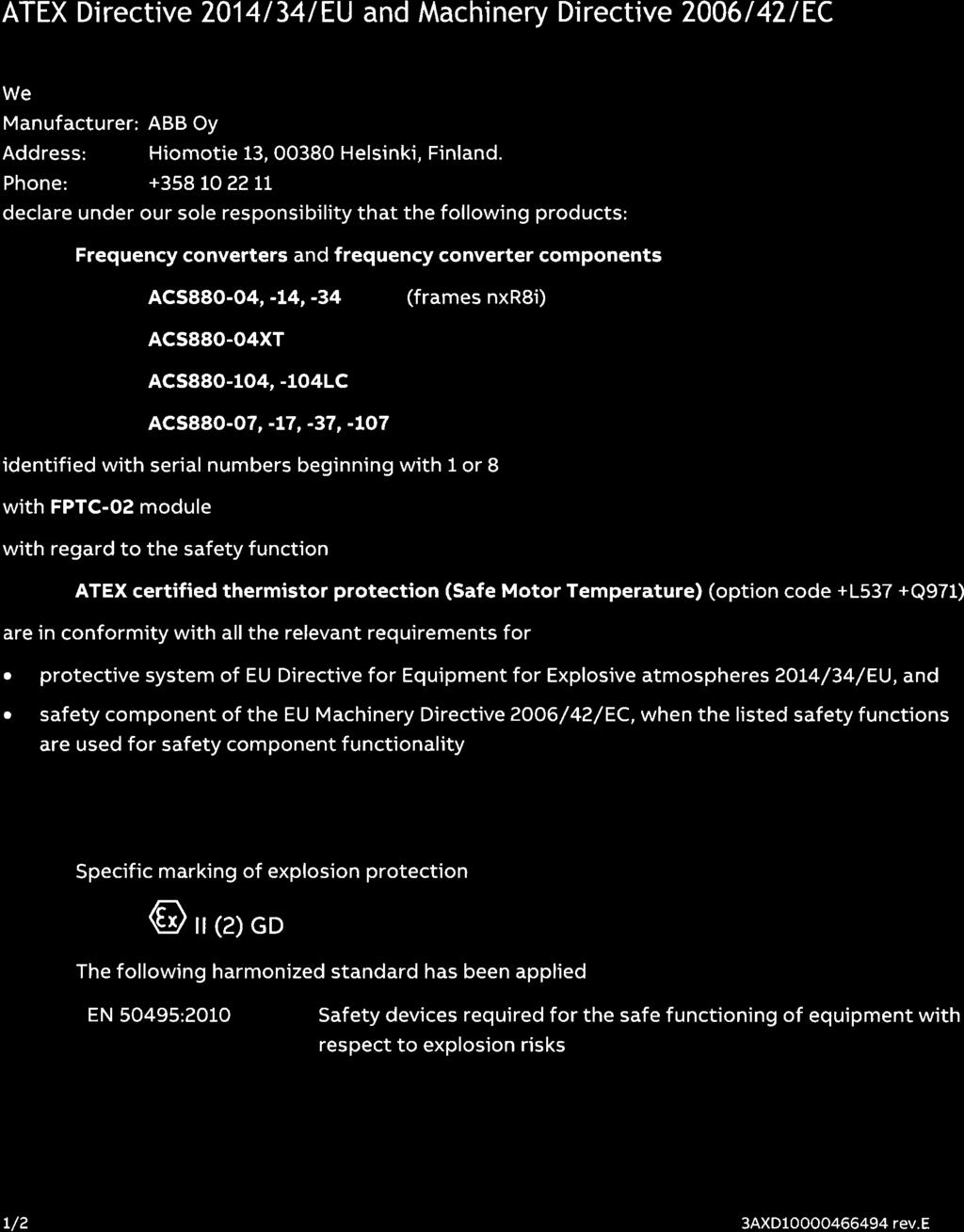
89 Compliance with the European Machinery Directive Technical data 89 The drive is an electronic product which is covered by the European Low Voltage Directive. However, the drive internal safety function of this manual (option +L537+Q971) is in the scope of the Machinery Directive as a safety component. This function complies with European harmonized standards such as EN/IEC The declarations of conformity are shown below. Compliance with the European ATEX Directive The safety function of this manual (option +L537+Q971) is within the scope of the ATEX product directive 2014/34/EU (previously 94/9/EC) as a protective system. The function complies with European harmonized standard EN The declarations of conformity are shown below.


90 90 Technical data


91 Technical data 91

92 92 Technical data

93 Technical data 93

94 94 Technical data ATEX certificate ATEX certificate for the Safe motor temperature function with the FPTC-02 module and ACS880 drive series (VTT 15 ATEX 050).


95 Technical data 95

96 96 Technical data Note: Check the latest version of the certificate in the ABB Library.

97 Technical data 97 TÜV Nord certificate TÜV Nord certificate for the FPTC-02 module and ACS880 drive series is attached below.
98 98 Technical data
99 Further information Product and service inquiries Address any inquiries about the product to your local ABB representative, quoting the type designation and serial number of the unit in question. A listing of ABB sales, support and service contacts can be found by navigating to Product training For information on ABB product training, navigate to new.abb.com/service/training. Providing feedback on ABB manuals Your comments on our manuals are welcome. Navigate to new.abb.com/drives/manuals-feedback-form. Document library on the Internet You can find manuals and other product documents in PDF format on the Internet at

100 Contact us 3AXD Rev C (EN)
Options for ABB drives. User s manual FPTC-02 ATEX-certified thermistor protection module, Ex II (2) GD (option +L537+Q971) for ACS880 drives
 GD (option +L537+Q971) for ACS880 drives") Options for ABB drives User s manual FPTC-02 ATEX-certified thermistor protection module, Ex II (2) GD (option +L537+Q971) for ACS880 drives List of related manuals Drive hardware manuals Code (EN) ACS880-01
Options for ABB drives User s manual FPTC-02 ATEX-certified thermistor protection module, Ex II (2) GD (option +L537+Q971) for ACS880 drives List of related manuals Drive hardware manuals Code (EN) ACS880-01
Options for ABB drives. User s manual FPTC-01 thermistor protection module (option +L536) for ACS880 drives
 for ACS880 drives") Options for ABB drives User s manual FPTC-01 thermistor protection module (option +L536) for ACS880 drives List of related manuals Drive hardware manuals Code (EN) ACS880-01 hardware manual 3AUA0000078093
Options for ABB drives User s manual FPTC-01 thermistor protection module (option +L536) for ACS880 drives List of related manuals Drive hardware manuals Code (EN) ACS880-01 hardware manual 3AUA0000078093
OPTIONS FOR ABB DRIVES CPTC-02 ATEX-certified thermistor protection module, Ex II (2) GD (+L537+Q971) User s manual
 GD (+L537+Q971) User s manual") OPTIONS FOR ABB DRIVES CPTC-02 ATEX-certified thermistor protection module, Ex II (2) GD (+L537+Q971) User s manual List of related manuals Drive hardware manuals and guides Code (English) Drive/converter/inverter
OPTIONS FOR ABB DRIVES CPTC-02 ATEX-certified thermistor protection module, Ex II (2) GD (+L537+Q971) User s manual List of related manuals Drive hardware manuals and guides Code (English) Drive/converter/inverter
Options for ABB drives. User s manual FSE-31 pulse encoder interface module
 Options for ABB drives User s manual FSE-31 pulse encoder interface module List of related manuals and guides Drive hardware manuals Code (EN) ACS880-01 hardware manual 3AUA0000078093 ACS880-04 hardware
Options for ABB drives. User s manual Prevention of unexpected start-up (option +Q950) for ACS880-07/17/37 drives
 for ACS880-07/17/37 drives") Options for ABB drives User s manual Prevention of unexpected start-up (option +Q950) for ACS880-07/17/37 drives List of related manuals Drive hardware manuals and guides ACS880-07 drives (560 to 2800
Options for ABB drives User s manual Prevention of unexpected start-up (option +Q950) for ACS880-07/17/37 drives List of related manuals Drive hardware manuals and guides ACS880-07 drives (560 to 2800
Options for ABB drives. User s manual Emergency stop, stop category 0 (option +Q951) for ACS880-07/17/37 drives
 for ACS880-07/17/37 drives") Options for ABB drives User s manual Emergency stop, stop category 0 (option +Q951) for ACS880-07/17/37 drives List of related manuals Drive hardware manuals and guides ACS880-07 drives (560 to 2800 kw)
Options for ABB drives User s manual Emergency stop, stop category 0 (option +Q951) for ACS880-07/17/37 drives List of related manuals Drive hardware manuals and guides ACS880-07 drives (560 to 2800 kw)
Options for ABB drives. User s manual Prevention of unexpected start-up (option +Q957) for ACS880-07/17/37 drives
 for ACS880-07/17/37 drives") Options for ABB drives User s manual Prevention of unexpected start-up (option +Q957) for ACS880-07/17/37 drives List of related manuals Drive hardware manuals and guides ACS880-07 drives (560 to 2800
Options for ABB drives User s manual Prevention of unexpected start-up (option +Q957) for ACS880-07/17/37 drives List of related manuals Drive hardware manuals and guides ACS880-07 drives (560 to 2800
Options for ABB drives. User s manual Emergency stop, stop category 1 (option +Q964) for ACS880-07/17/37 drives
 for ACS880-07/17/37 drives") Options for ABB drives User s manual Emergency stop, stop category 1 (option +Q964) for ACS880-07/17/37 drives List of related manuals Drive hardware manuals and guides ACS880-07 drives (560 to 2800 kw)
Options for ABB drives User s manual Emergency stop, stop category 1 (option +Q964) for ACS880-07/17/37 drives List of related manuals Drive hardware manuals and guides ACS880-07 drives (560 to 2800 kw)
Options for ABB drives, converters and inverters. User s manual FDIO-01 digital I/O extension module
 Options for ABB drives, converters and inverters User s manual FDIO-01 digital I/O extension module List of related manuals Drive manuals and guides ACS880-01 manuals ACS880-04 manuals ACS880-07 manuals
FSO Webnair FSO Safety Functions Module. ABB Group February 11, 2015 Slide 1
 FSO Webnair FSO Safety Functions Module February 11, 2015 Slide 1 Competence Requirements for ABB Commissioner / Service Engineer of ACS880 Drives with FSO The integrated Safety Function Module (FSO; option
Welcome to the Safety functions training module for ACS880 cabinet-built industrial drives.
 Welcome to the Safety functions training module for ACS880 cabinet-built industrial drives. 1 In this presentation we will discuss safety options for ACS880 cabinet-built drives, FSO-12 safety functions
User s Manual Pulse Encoder Interface Module OTAC-01
 Drive IT Low Voltage AC Drives User s Manual Pulse Encoder Interface Module OTAC-01 2 Safety WARNING! All electrical installation and maintenance work on the drive should be carried out by qualified electricians
Welcome to the overview of ACS880 functional safety, FSO-11 Safety functions module.
 Welcome to the overview of ACS880 functional safety, FSO-11 Safety functions module. 1 The e-learning sessions about FSO-11 safety functions module contain the following topics. A general overview More
Welcome to the safety functions configuration training module for ACS880 Cabinet-built industrial drives.
 Welcome to the safety functions configuration training module for ACS880 Cabinet-built industrial drives. 1 After viewing this presentation you will be able to describe: The functionality of cabinet-built
ABB industrial drives. Safety instructions ACS880 multidrive cabinets and modules
 ABB industrial drives Safety instructions ACS880 multidrive cabinets and modules Safety instructions ACS880 multidrive cabinets and modules Table of contents 2. Safety instructions 2017 ABB Oy. All Rights
Options for ABB drives, converters and inverters. User s manual FEA-03 F-series extension adapter
 Options for ABB drives, converters and inverters User s manual FEA-03 F-series extension adapter List of related manuals Option manuals and guides FEA-03 F-series extension adapter user s manual FDCO-01/02
ABB Drives. User s Manual Pulse Encoder Interface Module MTAC-01
 ABB Drives User s Manual Pulse Encoder Interface Module MTAC-01 Pulse Encoder Interface Module MTAC-01 User s Manual 3AFE68591091 REV B EN EFFECTIVE: 04.04.2006 2006 ABB Oy. All Rights Reserved. 5 Safety
SAFETY RELAY YRB-4EML-31S MAIN FEATURES
 SAFETY RELAY TYPE 4 SAFETY PROTECTION DEVICE FOR SAFETY LIGHT CURTAINS/BARRIERS MAIN FEATURES For safety light curtains and access control barriers, emergency stop, door switch Safety Integrity Level (SIL)
ABB industrial drives. Supplement ACS880 distributed I/O bus
 ABB industrial drives Supplement ACS880 distributed I/O bus List of related manuals General manuals Safety instructions for ACS880 multidrive cabinets and modules Safety instructions for ACS880 liquid-cooled
ABB industrial drives. EMC filter and ground-to-phase varistor disconnecting instructions ACS880 frames R1 to R11
 ABB industrial drives EMC filter and ground-to-phase varistor disconnecting instructions ACS880 frames R1 to R11 List of related manuals hardware manuals and guides Code (English) EMC filter and ground-to-phase
Original operating instructions Safety relay with relay outputs G1501S / / 2016
 Original operating instructions Safety relay with relay outputs G50S UK 8023637 / 00 02 / 206 Contents Preliminary note...4. Symbols used...4 2 Safety instructions...5 3 Items supplied...6 4 Functions
ABB Drives. User s Manual. Digital I/O Extension Module RDIO-01
 ABB Drives User s Manual Digital I/O Extension Module RDIO-01 Digital I/O Extension Module RDIO-01 User s Manual 3AFE 64485733 REV B EN EFFECTIVE: 10.2.2003 2003 ABB Oy. All Rights Reserved. Safety Instructions
ABB Drives. User s Manual. Modbus Adapter Module RMBA-01
 ABB Drives User s Manual Modbus Adapter Module RMBA-01 Modbus Adapter Module RMBA-01 User s Manual 3AFE 64498851 REV A EN EFFECTIVE: 1.3.2002 2002 ABB Oy. All Rights Reserved. Safety instructions Overview
Drive Technology \ Drive Automation \ System Integration \ Services. Manual. Electronic Motor DRC Functional Safety
 Drive Technology \ Drive Automation \ System Integration \ Services Manual Electronic Motor DRC Functional Safety Edition 02/2012 19376812 / EN SEW-EURODRIVE Driving the world Contents Contents 1 General
Original operating instructions Safety relay with relay outputs with and without delay G1502S / / 2016
 Original operating instructions Safety relay with relay outputs with and without delay UK G50S 803638 / 00 0 / 06 Contents Preliminary note...4. Symbols used...4 Safety instructions...5 3 Items supplied...6
ABB industrial drives. Supplement ACS880 override control program (option +N5450)
") ABB industrial drives Supplement ACS880 override control program (option +N5450) List of related manuals Drive firmware manuals ACS880 primary control program firmware manual ACS880 drives with primary
ABB industrial drives Supplement ACS880 override control program (option +N5450) List of related manuals Drive firmware manuals ACS880 primary control program firmware manual ACS880 drives with primary
MANUAL Functional Safety
 PROCESS AUTOMATION MANUAL Functional Safety Repeater KFD0-CS-(Ex)*.54*, KFD0-CS-(Ex)*.56* ISO9001 2 With regard to the supply of products, the current issue of the following document is applicable: The
Drive Technology \ Drive Automation \ System Integration \ Services. Manual. MOVITRAC MC07B Functional Safety
 Drive Technology \ Drive Automation \ System Integration \ Services Manual MOVITRAC Functional Safety Edition 12/2011 19396414 / EN SEW-EURODRIVE Driving the world Contents Contents 1 General Information...
ABB Drives. User s Manual. Analogue I/O Extension Module RAIO-01
 ABB Drives User s Manual Analogue I/O Extension Module RAIO-01 Analogue I/O Extension Module RAIO-01 User s Manual 3AFE 64484567 REV A EN EFFECTIVE: 1.2.2002 2002 ABB Oy. All Rights Reserved. Safety
Controller CMXH. Description STO. Safe Torque Off (STO) [ ]
![Controller CMXH. Description STO. Safe Torque Off (STO) [ ]](/thumbs/91/104782215.jpg "Controller CMXH. Description STO. Safe Torque Off (STO) [ ]") Controller CMXH Description STO Safe Torque Off (STO) 8062612 1603 [8062614] CMXH Translation of the original instructions CMXH-STO-EN Identification of hazards and instructions on how to prevent them:
Controller CMXH Description STO Safe Torque Off (STO) 8062612 1603 [8062614] CMXH Translation of the original instructions CMXH-STO-EN Identification of hazards and instructions on how to prevent them:
MANUAL Functional Safety
 PROCESS AUTOMATION MANUAL Functional Safety Switch Amplifier HiC283* ISO9001 2 With regard to the supply of products, the current issue of the following document is applicable: The General Terms of Delivery
Original operating instructions Fail-safe inductive sensor GF711S / / 2013
 Original operating instructions Fail-safe inductive sensor GF7S 8528 / 5 / 23 Contents Preliminary note...3. Explanation of symbols...3 2 Safety instructions...4 2. Safety-related requirements regarding
OPTION FOR ABB DRIVES, CONVERTERS AND INVERTERS FSCA-01 RS-485 adapter module User s manual
 OPTION FOR ABB DRIVES, CONVERTERS AND INVERTERS FSCA-01 RS-485 adapter module User s manual List of related manuals See section Related manuals on page 13. You can find manuals and other product documents
ABB Drives. User s Manual Modbus Adapter Module FMBA-01
 ABB Drives User s Manual Modbus Adapter Module FMBA-01 Modbus Adapter Module FMBA-01 User s Manual 3AFE68586704 REV A EN EFFECTIVE: 27.06.2005 2005 ABB Oy. All Rights Reserved. 5 Safety instructions
LOW VOLTAGE AC DRIVES. Crane control and safety with ACS880 drives
 LOW VOLTAGE AC DRIVES Crane control and safety with ACS880 drives 2 LOW VOLTAGE AC DRIVES BROCHURE Safety. Performance. Efficiency. Speed. Everything counts Overhead cranes need to be carefully designed
Drive Technology \ Drive Automation \ System Integration \ Services. Manual. MOVITRAC MC07B Functional Safety
 Drive Technology \ Drive Automation \ System Integration \ Services Manual MOVITRAC MC07B Functional Safety Edition 12/2011 19396414 / EN SEW-EURODRIVE Driving the world Contents Contents 1 General Information...
Low voltage switchgear and controlgear functional safety aspects
 Low voltage switchgear and controlgear functional safety aspects Guidance how to use low voltage switchgear and controlgear in functional safety applications Picture Siemens AG A message from the CAPIEL
Control unit SG-EFS 104/2W. EN Operating instructions. Innovative by tradition. Version SG-EFS 104/2W 24 V=/~
 Innovative by tradition. Control unit SG-EFS 104/2W EN Operating instructions Version 0.9 1005196 SG-EFS 104/2W 24 V=/~ Original instructions Mayser GmbH & Co. KG Örlinger Straße 1 3 89073 Ulm GERMANY
Checking the compatibility with IT (ungrounded) and corner-grounded delta systems. EMC filter +E200 (690 V drives and drive modules)
 and corner-grounded delta systems. EMC filter +E200 (690 V drives and drive modules)") Update notice Update notice 1 The notice concerns the ACS880-04XT hardware manuals listed below. Contents of the notice: Checking the compatibility of the drive with IT (ungrounded) and cornergrounded
Update notice Update notice 1 The notice concerns the ACS880-04XT hardware manuals listed below. Contents of the notice: Checking the compatibility of the drive with IT (ungrounded) and cornergrounded
EN BU Functional Safety. Supplementary manual for series SK 500E
 EN BU 0530 Functional Safety Supplementary manual for series SK 500E Functional Safety Supplementary manual for series SK 500E Table of Contents 1 Introduction... 4 1.1 General... 4 1.1.1 Documentation...
Polymer Electric. Operating Instructions. Control Unit SG-EFS 1X4 ZK2/1 8k2. Version 3
 Operating Instructions Control Unit SG-EFS 1X4 ZK2/1 8k2 Version 3 1003100 SG-EFS 104 ZK2/1 8k2 24 V=/~ 7500354 SG-EFS 134 ZK2/1 8k2 230 V~ Original instructions GmbH & Co. KG Polymer Electric Örlinger
Original operating instructions Fail-safe inductive sensor GI711S / / 2010
 Original operating instructions Fail-safe inductive sensor GI7S 704583 / 0 06 / 200 Contents Preliminary note 3. Explanation of symbols 3 2 Safety instructions 4 2. Safety-related requirements regarding
AS-i Safety Relay Output Module with Diagnostic Slave
 AS-i Safety Relay Output Module with Diagnostic Slave User Manual Revision date: 2013-01-30...supports the requirements for AS-i Safety up to SIL3 Subject to modifications without notice. Generally, this
Control unit SG-EFS 104/4L. EN Operating instructions. Innovative by tradition. Version SG-EFS 104/4L AC/DC 24 V
 Innovative by tradition. Control unit SG-EFS 104/4L EN Operating instructions Version 2 1004128 SG-EFS 104/4L AC/DC 24 V Original instructions Mayser GmbH & Co. KG Örlinger Straße 1 3 89073 Ulm GERMANY
Drive Technology \ Drive Automation \ System Integration \ Services. Manual. Control Cabinet Inverter MOVITRAC B Functional Safety
 Drive Technology \ Drive Automation \ System Integration \ Services Manual Control Cabinet Inverter MOVITRAC B Functional Safety Edition 05/2009 16811216 / EN SEW-EURODRIVE Driving the world Content Content
Operating instructions. Speed monitor D / / 2014
 Operating instructions Speed monitor D200 80005257 / 00 05 / 2014 Contents 1 Preliminary note...4 1.1 Symbols used...4 1.2 Warning signs used...4 2 Safety instructions...5 2.1 General...5 2.2 Target group...5
115/230 VAC Digital Input Module OHDI-01
 Drive IT Low Voltage AC Drives User s Manual 115/230 VAC Digital Input Module OHDI-01 OHD4 2 115/230 VAC Digital Input Module OHDI-01 Safety WARNING! All electrical installation and maintenance work on
Polymer Electric. Operating Instructions. Control Unit SG-RST 153. Version 0.3
 Operating Instructions Control Unit SGRST 153 Version 0.3 1004931 SGRST 153 Original instructions GmbH & Co. KG Örlinger Straße 1 3 89073 Ulm GERMANY Tel.: +49 731 20610 Fax: +49 731 2061222 EMail: info.ulm@mayser.com
Operating instructions. Switching amplifier DN0210 DN / / 2015
 Operating instructions Switching amplifier DN0210 DN0220 UK 80011079 / 00 01 / 2015 Contents 1 Preliminary note...4 1.1 Symbols used...4 1.2 Warning signs used...4 2 Safety instructions...5 2.1 General...5
Operating instructions AC010S Compact AS-i E-STOP safety module
 Operating instructions AC010S Compact AS-i E-STOP safety module Sachnr. 7390636_/00 05/2007 Contents Safety instructions............................. 3 Installation / Setup............................
MANUAL Functional Safety
 PROCESS AUTOMATION MANUAL Functional Safety Switch Amplifier KFD2-SOT3-Ex*(.LB)(.IO)(-Y1), KFD2-ST3-Ex*(.LB) ISO9001 2 With regard to the supply of products, the current issue of the following document
ATV32HU75N4 variable speed drive ATV kw V - 3 phase - with heat sink
 Characteristics variable speed drive ATV32-7.5 kw - 400 V - 3 phase - with heat sink Main Range of product Altivar 32 Product or component type Product destination Product specific application Function
ABB wind turbine converters. Supplement ACS slide-out frame (+P919)
") ABB wind turbine converters Supplement ACS800-67 slide-out frame (+P919) List of related manuals ACS800-67 manuals ACS800-67 wind turbine converters for asynchronous slip ring generators hardware manual
ABB wind turbine converters Supplement ACS800-67 slide-out frame (+P919) List of related manuals ACS800-67 manuals ACS800-67 wind turbine converters for asynchronous slip ring generators hardware manual
Operating instructions. Standstill monitor A / / 2011
 Operating instructions Standstill monitor A300 UK 1 2 3 4 5 6 7 8 7390337 / 01 02 / 2011 1 2 3 4 5 6 7 8 switchpoint min max pulse/min power Made in Germany ifm electronic gmbh D 45127 Essen func. I II
Controller CMXH-ST2 Key features
 Key features At a glance The controller controls two servo motors which drive an H-shaped rotating toothed belt. The toothed belt moves a slide, whose position is calculated by the controller from the
PSR-MS60. Safety relay for emergency stop, safety door and light grid monitoring. Data sheet. 1 Description
 SILCL IEC 62061 Safety relay for emergency stop, safety door and light grid monitoring Data sheet 106171_en_01 PHOENIX CONTACT 2015-05-19 1 Description Intended Use The PSR-MS60 safety relay can be used
SMVector Additional I/O Module Installation and Operation Manual
 SMVector Additional I/O Module Installation and Operation Manual About These Instructions This documentation applies to the optional Additional I/O module for the SMVector inverter and should be used in
vacon 100 optbj safety manual sto and atex option board ac drives
 vacon 00 ac drives optbj sto and atex option board safety manual vacon TABLE OF CONTENTS Document: DPD00470D Release date : 6006. Approvals.... General...8. References...9 3. Installation of OPTBJ board...0
SAFETY MANUAL SIL Switch Amplifier
 PROCESS AUTOMATION SAFETY MANUAL SIL Switch Amplifier KCD2-SOT-(Ex)*(.LB)(.SP), KCD2-ST-(Ex)*(.LB)(.SP) ISO9001 2 With regard to the supply of products, the current issue of the following document is applicable:
OPTION FOR ABB DRIVES, CONVERTERS AND INVERTERS FDNA-01 DeviceNet adapter module User s manual
 OPTION FOR ABB DRIVES, CONVERTERS AND INVERTERS FDNA-01 DeviceNet adapter module User s manual List of related manuals See section Related manuals on page 15. You can find manuals and other product documents
ACT20X-(2)HTI-(2)SAO Temperature/mA converter. Safety Manual
HTI-(2)SAO Temperature/mA converter. Safety Manual") ACT20X-(2)HTI-(2)SAO Temperature/mA converter Safety Manual 1.1 Revision history Version Date Change 00 04/2014 First Edition 01 11/2017 Products added 1.2 Validity This manual is valid for the following
ACT20X-(2)HTI-(2)SAO Temperature/mA converter Safety Manual 1.1 Revision history Version Date Change 00 04/2014 First Edition 01 11/2017 Products added 1.2 Validity This manual is valid for the following
ATV32HU11M2437 variable speed drive ATV32-1.1kW 200V - 1P - Bluetooth built-in - w heat sink
 Characteristics variable speed drive ATV32-1.1kW 200V - 1P - Bluetooth built-in - w heat sink Main Range of product Altivar 32 Product or component type Product destination Product specific application
ABB low voltage drives. Supplement External control unit (+P906) for ACH580-04, ACQ and ACS drives
 for ACH580-04, ACQ and ACS drives") ABB low voltage drives Supplement External control unit (+P906) for ACH580-04, ACQ580-04 and ACS580-04 drives List of related manuals Drive hardware manuals and guides External control unit (+P906) for
ABB low voltage drives Supplement External control unit (+P906) for ACH580-04, ACQ580-04 and ACS580-04 drives List of related manuals Drive hardware manuals and guides External control unit (+P906) for
* _1216* Drive Technology \ Drive Automation \ System Integration \ Services. Manual. Electronic Motor DRC..
 Drive Technology \ Drive Automation \ System Integration \ Services *22745866_1216* Manual Electronic Motor DRC.. Functional Safety Edition 12/2016 22745866/EN SEW-EURODRIVE Driving the world Contents
PowerFlex 700H AC Drive Safe Torque Off Option
 User Manual PowerFlex 700H AC Drive Safe Torque Off Option Catalog Number 20C-DG01 Important User Information Solid-state equipment has operational characteristics differing from those of electromechanical
Operating Instructions
 Innovative by tradition. Operating Instructions Control Unit SG-RSV 239 Version 1 1003986 SG-RSV 239/24 24 V= 1005372 SG-RSV 239/36 36 V= 1003271 SG-RSV 239 50-150 V= Mayser GmbH & Co. KG Örlinger Straße
AS-i Safety Relay Output Module with Diagnostic Slave
 AS-i Safety Relay Output Module with Diagnostic Slave User Manual...supports the requirements for AS-i Safety up to SIL3 Revision date: 2016-03-9 Subject to modifications without notice. Generally, this
ABB Micro drives. User s manual ACS250 drives ( hp) (600V Variants)
 (600V Variants)") ABB Micro drives User s manual ACS250 drives (0.5 20 hp) (600V Variants) List of related manuals Option manuals and guides ACS250 user s manual for 115-480V variants Code (English) 3AUA0000137830 You can
ABB Micro drives User s manual ACS250 drives (0.5 20 hp) (600V Variants) List of related manuals Option manuals and guides ACS250 user s manual for 115-480V variants Code (English) 3AUA0000137830 You can
Operating manual. INVEOR Functional Safety
 Operating manual INVEOR Functional Safety Legal notice KOSTAL Industrie Elektrik GmbH An der Bellmerei 10 58513 Lüdenscheid Germany Tel. +49 (0)2351 16-0 Fax + 49 (0)2351 16-2400 info-industrie@kostal.com
Brief description FSM MOV. for the ARS 2000 FS series servo drives
 The servo drive ARS 2000 FS with safety module FSM 2.0 - MOV is a product with safety-relevant functions and is intended for installation in machines or automation systems and for use as follows: in excellent
PSR-PS21. SIL coupling relay. Data sheet. 1 Description
 SIL coupling relay Data sheet 106253_en_00 PHOENIX CONTACT 2015-03-13 1 Description Intended Use The SIL coupling relay can be used for power adaptation and electrical isolation in high and low-demand
Altivar Process Variable Speed Drives ATV630, ATV650, ATV660, ATV680
 Altivar Process EAV64334 07/2015 Altivar Process Variable Speed Drives ATV630, ATV650, ATV660, ATV680 Safety Function Manual 07/2015 EAV64334.05 www.schneider-electric.com The information provided in this
ISO SINAMICS G110D FAQ
 Cover sheet Safe Torque Off (STO) of an AS-idriven SINAMICS G110D with SIL 3 in compliance with IEC 62061 or PL e in compliance with ISO 13849-1 SINAMICS G110D FAQ November 2012 Service & Support Answers
ATV32HD11N4 variable speed drive ATV32-11 kw V - 3 phase - with heat sink
 Product data sheet Characteristics ATV32HD11N4 variable speed drive ATV32-11 kw - 400 V - 3 phase - with heat sink Complementary Line current Apparent power Prospective line Isc Nominal output current
ATV32H075M2 variable speed drive ATV32-0,75 kw V - 1 phase - with heat sink
 Characteristics variable speed drive ATV32-0,75 kw - 200 V - 1 phase - with heat sink Main Range of product Altivar 32 Product or component type Product destination Product specific application Function
ATV320U07M2C variable speed drive ATV kW V - 1 phase - compact
 Characteristics variable speed drive ATV320-0.75kW - 200...240V - 1 phase - compact Main Range of product Product or component type Product specific application Device short name Format of the drive Product
Safety manual. This safety manual is valid for the following product versions: Version No. V1R0
 Safety manual HART TRANSPARENT driver 9107 This safety manual is valid for the following product versions: 9107-002 Version No. V1R0 0. CONTENTS 1. Observed standards... 2 2. Acronyms and abbreviations...
WHITE PAPER. Drive-based functional safety How variable speed drives are playing an increasingly important role in machine safety
 WHITE PAPER Drive-based functional safety How variable speed drives are playing an increasingly important role in machine safety 2 WHITE PAPER DRIVE-BASED FUNCTIONAL SAFETY Table of contents 003 Part 1
ATV650U30N4E variable speed drive ATV650-3kW V - IP55 - disconnect switch
 Characteristics variable speed drive ATV650-3kW - 380...480V - IP55 - disconnect switch Main Range of product Product or component type Product specific application Device short name Variant Product destination
ATV320U04N4C variable speed drive ATV kW V - 3 phase - compact
 Characteristics variable speed drive ATV320-0.37kW - 380...500V - 3 phase - compact Main Range of product Product or component type Product specific application Device short name Format of the drive Product
MACX MCR-SL-(2)I-2)I-ILP(-SP)
I-2)I-ILP(-SP)") Passive isolator, one and two channel Data sheet 106893_en_01 PHOENIX CONTACT 2015-12-07 1 Description The single- or dual-channel input loop powered 2-way isolator with plug-in connection technology is
Passive isolator, one and two channel Data sheet 106893_en_01 PHOENIX CONTACT 2015-12-07 1 Description The single- or dual-channel input loop powered 2-way isolator with plug-in connection technology is
QUICK START GUIDE. vau4/3. Frequency converter. operating instructions /12
 operating instructions QUICK START GUIDE Frequency converter vau4/3 28100241101 12/12 1 Safety information Warning of electrical shock! Danger to life! Electrical shock can cause serious injury or even
New developments about PL and SIL. Present harmonised versions, background and changes.
 Safety evevt 2017 Functional safety New developments about PL and SIL. Present harmonised versions, background and changes. siemens.com ISO/ TC 199 and IEC/ TC 44 joint working group 1 - Merging project
PSR UC/ESAM4/3X1/1X2/B
 Safety relay for emergency stop and safety door monitoring Data sheet 105318_en_02 PHOENIX CONTACT 2014-06-13 1 Description The safety relay can be used in safety circuits according to EN 60240-1 and IEC
ATV32HU30N4 variable speed drive ATV32-3 kw V - 3 phase - with heat sink
 Characteristics variable speed drive ATV32-3 kw - 400 V - 3 phase - with heat sink Complementary Line current Apparent power Prospective line Isc Nominal output current Maximum transient current Speed
OPTION FOR ABB DRIVES, CONVERTERS AND INVERTERS FEPL-02 Ethernet POWERLINK adapter module User s manual
 OPTION FOR ABB DRIVES, CONVERTERS AND INVERTERS FEPL-02 Ethernet POWERLINK adapter module User s manual List of related manuals See section Related manuals on page 15. You can find manuals and other product
ATV32HD11N4 variable speed drive ATV32-11 kw V - 3 phase - with heat sink
 Product datasheet Characteristics ATV32HD11N4 variable speed drive ATV32-11 kw - 400 V - 3 phase - with heat sink Complementary Line current Apparent power Prospective line Isc Nominal output current Maximum
FLEX Ex Spring Clamp Terminal Base
 Installation Instructions FLEX Ex Spring Clamp Terminal Base (Cat. No. 1797-TB3S) 1 10 11 4 Only remove this cover plug if connecting another terminal base unit. 3 5 6 12 2 7 8 9 41253 Component Identification
- Alii -,..., ~~~~~~~~'-~" ..., ,..- ))) --t ..., )(1. User s manual FEPL-02 Ethernet POWERLINK adapter module. IIIIIJ!ll"
)) --t ..., )(1. User s manual FEPL-02 Ethernet POWERLINK adapter module. IIIIIJ!ll") Options for ABB drives, converters and inverters User s manual FEPL-02 Ethernet POWERLINK adapter module,..- ))) --t - Alii - -,...,..., IIIIIJ!ll"...,,, FEPL ~ 02,.., " ETHERNET powerljnk ADApTER _,,""
Options for ABB drives, converters and inverters User s manual FEPL-02 Ethernet POWERLINK adapter module,..- ))) --t - Alii - -,...,..., IIIIIJ!ll"...,,, FEPL ~ 02,.., " ETHERNET powerljnk ADApTER _,,""
User s Manual. ACS550-PD Stock 3R Irrigation Packaged Drive Supplement to ACS550-U1 User s Manual
 User s Manual ACS550-PD Stock 3R Irrigation Packaged Drive Supplement to ACS550-U1 User s Manual 2 ACS550-PD 3R Irrigation Packaged Drive ACS550 Drive Manuals GENERAL MANUALS ACS550-U1 User s Manual (1
Original operating instructions Fail-safe inductive sensor GG711S
 Original operating instructions Fail-safe inductive sensor GG7S 8236522 / 2 / 26 Contents Preliminary note...3. Symbols used...3.2 Warning signs used...3 2 Safety instructions...4 2. Safety-related requirements
Original operating instructions Fail-safe inductive sensor GI712S
 Original operating instructions Fail-safe inductive sensor GI712S 80236527 / 00 12 / 2016 Contents 1 Preliminary note...3 1.1 Symbols used...3 1.2 Warning signs used...3 2 Safety instructions...4 2.1 Safety-related
ATV32HU40N4 variable speed drive ATV32-4 kw V - 3 phase - with heat sink
 Characteristics variable speed drive ATV32-4 kw - 400 V - 3 phase - with heat sink Complementary Product destination Supply voltage limits Main Range of product Altivar 32 Product or component type Product
PSR-PC50. SIL 3 coupling relay for safety-related switch on. Data sheet. 1 Description
 SIL 3 coupling relay for safety-related switch on Data sheet 105818_en_01 PHOENIX CONTACT 2014-08-18 1 Description The PSR-PC50 SIL coupling relay can be used for power adaptation and electrical isolation
Keystone OM3 - EPI-2 Local Interface Module Installation and Maintenance Instructions
 Index 1 Optional module 3: Local Interface module... 1 2 Installation... 2 3 Description of OM3 Local Interface... 4 4 To locally operate the actuator... 4 5 OM3 wiring diagram... 5 6 Identification...
ATV32HU30N4 variable speed drive ATV32-3 kw V - 3 phase
 Product datasheet Characteristics ATV32HU30N4 variable speed drive ATV32-3 kw - 400 V - 3 phase - with heat sink Complementary Line current Apparent power Prospective line Isc Nominal output current Maximum
REDUNDANCY MODULE TSP-REM360 AND TSP-REM600
 REDUNDANCY MODULE TSP-REM360 AND TSP-REM600 Operating Instructions Seite 1 Dimensions drawings: TSP-REM360 Weight: 0.882lb Gewicht: 0.40kg Seite 2 Dimensions drawings: TSP-REM600 Bottom view Top view Side
XPSMCMx Fieldbus Expansion Modules Instruction Sheet (Original Language)
") XPSMCMx Fieldbus Expansion Modules EAV8283001 12/2014 XPSMCMx Fieldbus Expansion Modules Instruction Sheet (Original Language) 12/2014 EAV8283001.00 www.schneider-electric.com The information provided
XPSMCMx Fieldbus Expansion Modules EAV8283001 12/2014 XPSMCMx Fieldbus Expansion Modules Instruction Sheet (Original Language) 12/2014 EAV8283001.00 www.schneider-electric.com The information provided
ATV930U30M3 variable speed drive - ATV930-3kW - 200/240Vwith braking unit - IP21
 Characteristics variable speed drive - ATV930-3kW - 200/240Vwith braking unit - IP21 Main Range of product Product or component type Device application Device short name Variant Product destination Mounting
LXM32AD18N4 motion servo drive - Lexium 32 - three-phase supply voltage 208/480V kw
 Characteristics motion servo drive - Lexium 32 - three-phase supply voltage 208/480V - 1.8 kw Complementary Switching frequency Overvoltage category Leakage current Output voltage Electrical isolation