Sierra Radio Systems. Making a Keyer with the. HamStack. Project Platform
|
|
|
- Laura Powers
- 5 years ago
- Views:
Transcription

1 Sierra Radio Systems Making a Keyer with the HamStack Project Platform
2 Introduction The HamStack Project Board includes primary interface elements needed to make a high quality CW keyer. Using the LCD display and a rotary encoder, it is fairly easy to implement a very nice interface to adjust the parameters of the keyer. These same concepts can be used for the user interface for any number of other projects. This example is programmed in C, using the Microchip MPLAB integrated development environment and C18 compiler. The Hamstack C function library contains most of the low level elements needed to implement the keyer, including LCD support and interrupt driven timers, tone generation, keyer implementation in encoder support. Refer to the HamStack Introduction and HamStack C Programming manuals for more information. A precompiled hex file with the keyer program is included for those that just want to try out the keyer as is. -2-

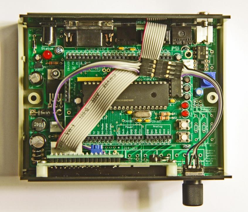
3 Setting up the Hardware The prototype version of the keyer is shown below. The following items are needed to complete the project: HamStack CPU board HamStack project board 2 line x 16 character LCD module with interface board and cable Panasonic EVE-JBBF2020B rotary encoder (Digikey P12336-ND) H11D1 opto-isolator, or Vishay LH1540AT solid state relay (Mouser 782- LH1540AT) 0.5 diameter, 6mm shaft knob (Digikey ND) If you want to enclose the keyer in one of the Hammond plastic boxes which the project board is designed to mount into, then you should not install the screw terminals on the project board. There is not enough room for the LCD module to be mounted in the front panel of the box if the screw terminals are in place. Even with the terminals removed, there is barely enough room for the LCD board above the project board the hole in the panel must be cut so that the top of the LCD circuit board aligns with the top of the panel. For our prototype, we cut custom black front and back panels. It is also possible to carefully cut openings for the LCD, encoder and back connectors in the black panel supplied with the enclosure. The LCD board was attached to threaded nylon spacers that were subsequently super-glued to the back of the front panel. Either of the opto-isolators will work. There are two sockets on the project board for the opto-isolator. The one closest to the output connector is wired for the solid state relay; the other is for the transistor switch opto-isolator. An H11D1 is included with the -3-

4 project board. It works with only one polarity. If you are keying a modern, solid state transmitter, then the center pin is the keyer pin, to be connected to the tip of the plug going into the transmitter. If you are keying a negative grid block keyed tube transmitter, then the polarity must be reversed connect the outside of the connector to the key line. The solid state relay is polarity independent and can be wired the same way for either +5V or V keying. When wiring the key output to the transmitter, do not connect the project board ground to the transmitter ground. We have had problems with both wall wart power supply noise getting into the receiver, and transmitter RF messing up the keyer when that was done. With the connection only through the opto-isolator outputs, there have been no problems. The encoder wiring diagram is shown to the right. The wiring is as follows: One of the COM pins is connected to ground (far left screw terminal on the project board) SW pin to A4 A pin to E2 B pin to E1 Pin A is always off at the detented steady point. Pin B transitions at or near the detented steady point. You should check this with an ohmmeter. Encoder Side in the diagram from the datasheet means the view from the shaft end. The key is connected with the dot switch connected to the tip of the 3.5 mm stereo plug. Left handed operation is accommodated in the software. Project Board Modifications There are a few modifications to the project board that are needed. 1. The switching power regulator on the board will generate significant noise if it is not properly bypassed. In rev. 1.0 of the board, two 0.1 uf monolithic ceramic capacitor should be soldered directly to the pins of the regulator, so that they are in parallel with the large electrolytics that are already in place. 2. The encoder A and B switches will not work without pull-up resistors from the processor input pin to 5 V. There is a tiny prototyping area in the corner of the board with room for a few vertically mounted 10k Ohm 1/4 watt resistors. Jumpers can connect these to regulated 5V and to the E1 and E2 processor pins. The encoder push button switch does not need an additional pull-up because it is wired in parallel with the CPU board mode switch which already has a pull-up. 3. A jumper is wired from the A4/mode pin to the B input (6 th from the left along the screw terminal connections) on the project board. This provides a connection on the project board edge for the push to select switch on the encoder. -4-

5 4. The op amp output of the tone generation filter cannot drive loads of less than 100 Ohms without severe distortion unless the level is very low. The tone generator runs at a full duty cycle swing, generating nearly 5V p-p tone amplitude in order to minimize quantization distortion from the 8 bit tone generation algorithm that is used. You can cut a trace from the output potentiometer and insert a 100 Ohm resistor to solve this problem. If you do not drive low impedance or a long cable with lots of capacitance, this may not be necessary. 5. One of the op amps in the MCP6004 quad op amp package is not used. The microchip datasheet states that unused op amps should have their inputs tied either to the supply rails or configured as a unity gain amplifier with the input ties to a bias voltage at ½ of the supply voltage. There is a 2.5V reference regulator on the board. The op amp should be wired to satisfy this condition unless you are wiring it to be used for something else. We did not detect any significant noise problem before this is done, so you might get away with ignoring this advice. 6. The location marked C11 on the project board should be populated with a jumper wire, not a 0.1 uf capacitor. This is necessary to set the correct DC bias level inside the tone generator filter. The photo below shows the 10k Ohm resistors added for digital input pull-ups. -5-

6 The photo below shows the bottom of the project board, with all of the modifications added. Note that the project board screw terminals were not installed. This necessary to allow room for the LCD panel tp project through a hole in the project board case front panel. Project board bottom view, with modifications The top left is the area with the pull-up resistors, with wires added to +5V (uninsulated), and to the E1 and E2 pins. There is also a jumper from the project board A connector to the CPU board A4 pin. The two capacitors are the bypass capacitors at the switching regulator. Note the very short leads. The long jumper from the lower left to the middle of the board connects between the 2.5V reference output and the +input of the spare op amp (pin 5). There is also a short jumper between pins 6 and 7. The 100 Ohm resistor jumpers across a gap cut in the trace at the output of the tone volume potentiometer. -6-
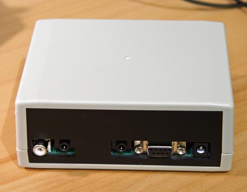
7 Additional Packaging Photos -7-
8 Operation On power up, the prototype code shows the CW speed on the bottom line of the display. It can be changed by rotating the encoder knob. You can adjust it while actively sending. By pushing on the encoder button, you can change the display and encoder operation to set other keyer parameters. In the prototype code, successive presses of the button will cycle through setting speed, keyer mode, left handed operation, keyer weight, sidetone frequency, minimum character WPM (Farnsworth spacing), and back to speed. Rotate the encoder to change these parameters. If you do nothing for a few seconds, the display will revert back to showing the CW speed. Changes in parameters are automatically saved to on-chip data EEPROM, so that the last settings used are restored on power up. The keyer modes are simple keyer, iambic a, iambic b, and iambic b2. Iambic b inserts an extra element if both paddles are pressed while the dot or dash is active. Iambic b2 is between iambic a and iambic b, recognizing the extra element only during the gap after the element. More elaborate code is planned to capture, send, and display memory contents, to adjust the keying weight (in milliseconds additional relative dot and dash length, not percent, which is mostly useless), and maybe eventually to read incoming CW. -8-
9 Software Hex files compiled for the 18F4620 with a 10 MHz crystal and the 18F46K22 with a 16 MHz crystal are provided. Use any PIC programmer to load those into your CPU. For other situations, or to modify the code to suit your own taste, you must edit and compile the code yourself. You will need to download and install MPLab and the C18 compiler from the Microchip web site in order to edit and compile the program yourself. Download and unzip the keyer_prototype.zip file from the Hamstack web site. Unzip it to a location of your choice. Start MPLAB, go to File/Open Workspace, navigate to the directory where you put the keyer_project files, and open keyer.mcw. Click on keyer_example.c in the project window to edit the main keyer program. The main keyer code is in the file keyerint.c in the hamstacklib directory. Be careful if you edit this. Interrupt code can be difficult to debug. If you just need to change clock rate click on the user_options.h file and edit the CLOCKFREQ entry. Recompile and program your controller to test your new version. Details on using MPLab and C18 to do your own projects are available in the HamStack C Programming Manual. -9-
Sierra Radio Systems. HamStack. Project Board Reference Manual V1.0
 Sierra Radio Systems HamStack Project Board Reference Manual V1.0 Welcome HamStack Project Board Reference Manual Revision 1.0.3 2011 George Zafiropoulos, KJ6VU and John Best, KJ6K This guide provides
The CW Machine Hardware
 The CW Machine Hardware 2010 Ulrich H. Steinberg Contents Introduction...2 Connecting the Hardware...3 The Configuration Switches...5 Power Considerations...7 Serial Communication...8 Installing the USB-Serial
The CW Machine Hardware
 The CW Machine Hardware 2017 Ulrich H. Steinberg The CW Machine Hardware Version 2.3 1 Contents Introduction...3 Connecting the Hardware...4 The Configuration Switches...6 Power Considerations...8 Serial
Shack Clock kit. U3S Rev 2 PCB 1. Introduction
 Shack Clock kit U3S Rev 2 PCB 1. Introduction Thank you for purchasing the QRP Labs Shack Clock kit. This clock uses the Ultimate3S QRSS/WSPR kit hardware, but a different firmware version. It can be used
Schematic Diagram: R2,R3,R4,R7 are ¼ Watt; R5,R6 are 220 Ohm ½ Watt (or two 470 Ohm ¼ Watt in parallel)
") Nano DDS VFO Rev_2 Assembly Manual Farrukh Zia, K2ZIA, 2016_0130 Featured in ARRL QST March 2016 Issue Nano DDS VFO is a modification of the original VFO design in Arduino Projects for Amateur Radio by
Nano DDS VFO Rev_2 Assembly Manual Farrukh Zia, K2ZIA, 2016_0130 Featured in ARRL QST March 2016 Issue Nano DDS VFO is a modification of the original VFO design in Arduino Projects for Amateur Radio by
Universal Keying Adapter 3+
 Universal Keying Adapter 3+ The Universal Keying Adapter Version 3+ kit will allow you to key nearly any transmitter or transceiver with a straight key, electronic keyer, computer serial or parallel port
Shack Clock kit PCB Revision: QCU Rev 1 or QCU Rev 3
 1. Introduction Shack Clock kit PCB Revision: QCU Rev 1 or QCU Rev 3 Thank you for purchasing this QRP Labs Shack Clock kit. The kit uses the same PCB and bag of components as some other QRP Labs kits.
VFO/Signal Generator kit PCB Revision QCU Rev 1 or QCU Rev 3
 1. Introduction VFO/Signal Generator kit PCB Revision QCU Rev 1 or QCU Rev 3 Thank you for purchasing this QRP Labs kit. The QRP Labs kit range is modular. The kit uses the same PCB and bag of components
N8VEM S-100 BACKPLANE VERSION 04 MAY 3, 2015 J.B.
 N8VEM S-100 BACKPLANE VERSION 04 MAY 3, 2015 J.B. Background. This board is a copy of Andrew Lynch s Version 03 board (with 8 slots) but with added features. Added features: 9 SLOT Active Termination (copied
GLiPIC Ver C Assembly manual Ver 1.0
 GLiPIC Ver C Assembly manual Ver 1.0 Last Rev 1.1 Oct 30, 2001 Author: Ranjit Diol Disclaimer and Terms of Agreement As with any kit, only the individual parts supplied are guaranteed against defects and
DEV-1 HamStack Development Board
 Sierra Radio Systems DEV-1 HamStack Development Board Reference Manual Version 1.0 Contents Introduction Hardware Compiler overview Program structure Code examples Sample projects For more information,
WinKey V6 PCB Assembly Guide Version /4/2013
 WinKey V6 PCB Assembly uide Version.4 2/4/203 This document describes the assembly, checkout, and hook up of the KEL Winkey2 Serial Kit with a version V6 PCB. This design is powered directly off the PC
MFJ-484 GRANDMASTER MEMORY KEYER CONTROL FUNCTIONS
 MFJ-484 GRANDMASTER MEMORY KEYER The MFJ-484 is a highly sophisticated memory keyer using 15 state-of-the-art Integrated Circuits and 4 Random Access Memories which are standards of the industry. It provides
Arduino shield kit. 1) Low Pass Filter (LPF) kit (available for LF/MF/HF/VHF bands 2,200m to 6m)
 Low Pass Filter (LPF) kit (available for LF/MF/HF/VHF bands 2,200m to 6m)") Arduino shield kit 1. Introduction The QRP Labs Arduino shield kit is a versatile shield that can be used for various purposes. Write your own Arduino sketch to define the functionality! For example: 1)
Arduino shield kit 1. Introduction The QRP Labs Arduino shield kit is a versatile shield that can be used for various purposes. Write your own Arduino sketch to define the functionality! For example: 1)
K8+ Single Chip Keyer Manual August 13, 1998 Steven T. Elliott - K1EL
 Introduction K8+ Single Chip Keyer Manual August 13, 1998 Steven T. Elliott - K1EL This manual will describe the operation of the K8+ Keyer which is a low cost automatic Morse keyer designed by Steve,
Sierra Radio Systems. Digital Compass. Reference Manual. Version 1.0
 Sierra Radio Systems Digital Compass Reference Manual Version 1.0 Contents Digital compass board RS485 power injector For more information, go to the Sierra Radio Systems web site at www.sierraradio.net
High Power (15W + 15W) Stereo Amplifier
 Stereo Amplifier") High Power (15W + 15W) Stereo Amplifier Build Instructions Issue 1.0 Build Instructions Before you put any components in the board or pick up the soldering iron, just take a look at the Printed Circuit
High Power (15W + 15W) Stereo Amplifier Build Instructions Issue 1.0 Build Instructions Before you put any components in the board or pick up the soldering iron, just take a look at the Printed Circuit
Morse Code Practice Oscillator
 Features Description Keyer speed range: Limited only by keying source True Sine wave tone output Tone Volume Control Tone Frequency Control Internal Speaker 1/8 External Speaker/Headphone Jack RCA Key
Building and using JasperMIDI
 Building and using JasperMIDI Table of Contents Introduction... Bill Of Materials... 2 Building Choices... 3 Construction... 4 Installing in a Jasper enclosure... 5 Standalone use... 6 Using JasperMIDI...
Phi-panel backpack assembly and keypad options Dr. John Liu 12/16/2012
 Phi-panel backpack assembly and keypad options Dr. John Liu 12/16/2012 1. Introduction:... 3 Currently available:... 3 2. Backpack assembly... 4 3. Connecting to a keypad... 6 4. Rotary encoder keypads...
MemoryKeyerV2.0.ino (AtoM.h, MtoA.h, Canned.h)
") MemoryKeyerV2.0.ino (AtoM.h, MtoA.h, Canned.h) This is an Arduino sketch that acts as an iambic memory keyer for amateur radio use. It can easily be constructed in a Standard Arduino Enclosure (Altoids
MemoryKeyerV2.0.ino (AtoM.h, MtoA.h, Canned.h) This is an Arduino sketch that acts as an iambic memory keyer for amateur radio use. It can easily be constructed in a Standard Arduino Enclosure (Altoids
C S Technology Ltd. cstech.co.uk. DTMF display 32 kit with 2 line x 16 LCD display
 C S Technology Ltd cstech.co.uk DTMF display 32 kit with 2 line x 16 LCD display Our DTMF display can display up to 32 characters (16 per line). The display can be cleared by a button (not supplied) or
Section 5: Installing Parts from the Controls and Connectors Bag
 Section 5: Installing Parts from the Controls and Connectors Bag 1) Install Pinheaders & Sockets Using the Component Layout Diagram in Appendix A as a guide, install all pinheaders and strip sockets on
ON4AKH Antenna Rotator controller Version 1.0
 ON4AKH Antenna Rotator controller Version 1.0 1. Some construction tips The project consists out of 3 boards. The 1 st board is the main board containing the PIC micro controller and the H-bridge components
Assembly Instructions (8/14/2014) Your kit should contain the following items. If you find a part missing, please contact NeoLoch for a replacement.
 Your kit should contain the following items. If you find a part missing, please contact NeoLoch for a replacement.") NeoLoch NLT-28P-LCD-5S Assembly Instructions (8/14/2014) Your kit should contain the following items. If you find a part missing, please contact NeoLoch for a replacement. Kit contents: 1 Printed circuit
NeoLoch NLT-28P-LCD-5S Assembly Instructions (8/14/2014) Your kit should contain the following items. If you find a part missing, please contact NeoLoch for a replacement. Kit contents: 1 Printed circuit
KEYLITE. Specifications: The Keylite keys your rig with paddles or an IBM compatible Keyboard. Power Requirements: 9V-14V
 KEYLITE The Keylite keys your rig with paddles or an IBM compatible Keyboard. Specifications: Power Requirements: 9V-14V Maximum current draw: Less than 20ma plus Keyboard. Keyboard input: Standard IBM
Touch Sense Controller
 Touch Sense Controller Paul Boston May 11, 2011 (Modified May 22, 2014) (Modified Dec 28, 2015) The Touch Sense Controller is a microprocessor-controlled circuit designed to provide a switch closure when
Storage Card Interface Kit
 Storage Card Interface Kit for MultiMediaCards(MMC) and Secure Digital Cards (SD) MMSD3K The MMSD3K is complete development kit interfaced to a SD or MMC card. This board ideal for projects that involve
Microsystems. SCI-6 Sound Card Interface Kit Version 1.09 January 2015
 UM Unified Microsystems SCI-6 Sound Card Interface Kit Version 1.09 January 2015 The SCI-6 interface was designed to be a low cost, high quality interface between your PC s sound card and radio transceiver.
DELUXE STEREO AMPLIFIER KIT
 ESSENTIAL INFORMATION BUILD INSTRUCTIONS CHECKING YOUR PCB & FAULT-FINDING MECHANICAL DETAILS HOW THE KIT WORKS CREATE YOUR OWN SPEAKER DOCK WITH THIS DELUXE STEREO AMPLIFIER KIT Version 2.0 Build Instructions
Insert the male, 90 angled, 2x10 connectors into the corresponding 2x10 sockets and put them in place, flat under the PCB. Solder.
 MC624 Assembly guide Safety warning The kits are main powered and use potentially lethal voltages. Under no circumstance should someone undertake the realisation of a kit unless he has full knowledge about
Butterfly Laser Diode Mount
 LM14S2 Butterfly Laser Diode Mount Operating Manual LM14S2 Laser On TEC Driver LD Driver THORLABS, Inc. Ph: (973) 579-7227 435 Route 206N Fax: (973) 383-8406 Newton, NJ 07860 USA www.thorlabs.com 10614-D02
Assembly Instructions for the KA Electronics Elliptic Equalizer
 Assembly Instructions for the KA Electronics Elliptic Equalizer Install IC sockets Elliptic Equalizer PC Board Stuffing Guide Place the PC Board on the work bench silkscreen side face up. Place twelve
SharpSky Focuser Construction. SharpSky Focuser. Construction Document V st December 2012 Dave Trewren 1
 SharpSky Focuser Construction Document V0.12 1st December 2012 Dave Trewren 1 Contents 1 General... 3 1.1 Change Record... 3 1.2 References... 3 2 Introduction... 5 3 SharpSky driver installation... 5
Button Code Kit. Assembly Instructions and User Guide. Single Button Code Entry System
 Button Code Kit Single Button Code Entry System Assembly Instructions and User Guide Rev 1.0 December 2009 www.alan-parekh.com Copyright 2009 Alan Electronic Projects Inc. 1. Introduction... 4 1.1 Concept
Rapid40i PIC Prototyping PCB User Manual
 Description This is a PCB designed to facilitate the rapid prototyping of a device based on a 40 pin Microchip PIC microcontroller. To allow users to focus on their application, we take care of key housekeeping
8051 Intermidiate Development Board. Product Manual. Contents. 1) Overview 2) Features 3) Using the board 4) Troubleshooting and getting help
 Overview 2) Features 3) Using the board 4) Troubleshooting and getting help") 8051 Intermidiate Development Board Product Manual Contents 1) Overview 2) Features 3) Using the board 4) Troubleshooting and getting help 1. Overview 2. Features The board is built on a high quality FR-4(1.6
8051 Intermidiate Development Board Product Manual Contents 1) Overview 2) Features 3) Using the board 4) Troubleshooting and getting help 1. Overview 2. Features The board is built on a high quality FR-4(1.6
ARES 2 Tone Sequential Tone Decoder Kit Assembly Instructions
 Tools Required: ARES Tone Sequential Tone Decoder Kit Assembly nstructions 3/8 Electric Drill Soldering ron Wire Strippers Needle Nose Pliers Wire Cutters Ruler 60/40 Solder Phillips Screw Driver /8, 5/64,
KPIC-0818P (V050919) Devices Included in this Data sheet: KPIC-0818P
 Devices Included in this Data sheet: KPIC-0818P") Devices Included in this Data sheet: KPIC-0818P Features: Carefully designed prototyping area Accepts 8 pin PIC12 series micro-controllers Accepts 14 and 18 Pin PIC16 series Accepts some 8,14 and 18 pin
Devices Included in this Data sheet: KPIC-0818P Features: Carefully designed prototyping area Accepts 8 pin PIC12 series micro-controllers Accepts 14 and 18 Pin PIC16 series Accepts some 8,14 and 18 pin
QRPGuys Digital Dial/Frequency Counter
 QRPGuys Digital Dial/Frequency Counter First, familiarize yourself with the parts and check for all the components. If a part is missing, please contact us and we will send one. You must use qrpguys.parts@gmail.com
Cumbria Designs T-1. C-1 Controller. User Manual
 Cumbria Designs T-1 C-1 Controller User Manual CONTENTS 1 INTRODUCTION 2 2 CIRCUIT DESCRIPTION 2 3 ASSEMBLY 3 4 CONNECTIONS AND CONFIGURATION 4 5 TESTING 6 Appendix A C-1 Circuit Diagram and PCB Component
PIC 28 Pin Board Documentation. Update Version 5.0
 PIC 28 Pin Board Documentation Update 2009.10 Version 5.0 Table of Contents PIC 28 Pin Board Documentation... 1 Table of Contents... 2 Introduction... 3 Circuit Schematic... 4 The following is the Circuit
Assembly Instructions for 128x64 Graphics Display Unit
 02/15/10 version 1.0 Assembly Instructions for 128x64 Graphics Display Unit This document describes the physical assembly of the Graphic Display unit for the 16 Bit Experimenter 128x64 Graphics kit. It
CV Arpeggiator Rev 2 Build Documentation.
 CV Arpeggiator Rev Build Documentation. Last updated 8-0-03 The CV Arpeggiator is a modular synth project used for creating arpeggios of control voltage. It utilizes a custom programmed PIC 6F685 micro
STAGE INTERCOM KIT 1.1 SPECIFICATION. General: The lower section is a small power amplifier designed to drive headphones or a small 8ohm speaker.
 STAGE INTERCOM KIT Version 2.1.1 - March 2018 - EduTek Ltd 1.0 DESCRIPTION This intercom module comprises of two separate circuits sharing the same supply. The upper section is a pre-amplifier designed
The i-kaktusss. Iambic Keyer And Koch Trainer Using a Seventeen Segment Screen.
 The i-kaktusss Iambic Keyer And Koch Trainer Using a Seventeen Segment Screen. Building the i-kaktusss An assembly manual for the i-kaktusss iambic keyer and koch trainer using a seventeen segment screen.
4.0 Blue LED DCF77 Clock documentation
 4.0 Blue LED DCF77 Clock documentation 1. LED Clock Main Board PCB mounting: Mount and solder the eight wire bridges. Mount and solder resistors R16, R18, R20, R22. Mount and solder capacitors C1 C3 (pitch
CP5176 Assembly guide. Soldering. CP5176 Assembly guide Main PCB PCB split. Document revision 2.1 Last modification : 12/11/17
 CP5176 Assembly guide Safety warning The kits are main powered and use potentially lethal voltages. Under no circumstance should someone undertake the realisation of a kit unless he has full knowledge
Dwarf Boards. DB057 : 40-pin controller board
 Dwarf Boards DB057 : 40-pin controller board PICmicro, In-Circuit Serial Programming and ICSP are registered trademarks of Microchip Technology Inc. DB057 for USB PIC DB057 for non-usb PIC Introduction
solutions for teaching and learning
 RKP18Motor Component List and Instructions PCB layout Constructed PCB Schematic Diagram RKP18Motor Project PCB Page 1 Description The RKP18Motor project PCB has been designed to use PIC microcontrollers
Using solderless breadboards
 Page 1 of 9 Using solderless breadboards This document describes how to use the solderless breadboards available in the experimental didactic lab (LED, previously LADISPE) of Politecnico di Torino. 1 Setting
EQ573 Assembly guide. EQ573 Assembly guide Main board 1. Diodes. 2. Resistors (1) 3. Test pins. 4. Ceramic capacitors.
 3. Test pins. 4. Ceramic capacitors.") EQ573 Assembly guide Safety warning The kits are main powered and use potentially lethal voltages. Under no circumstance should someone undertake the realisation of a kit unless he has full knowledge about
EQ573 Assembly guide Safety warning The kits are main powered and use potentially lethal voltages. Under no circumstance should someone undertake the realisation of a kit unless he has full knowledge about
Assembly Instructions for the KA Electronics RIAA EQ Monitor Switcher
 Assembly Instructions for the KA Electronics RIAA EQ Monitor Switcher Install IC sockets EQ Monitor Switcher PC Board Stuffing Guide Place the PC Board on the bench silkscreen side face up. Drop eleven
K1EL Morse Code Practice Oscillator CPO
 Features This is an oscillator not a Morse keyer Input source can be a keyer or straight key Near Sine wave tone output CPO Tone Volume Control CPO Tone Frequency Control Use headphones or external speaker
Pacific Antenna Easy TR Switch Kit
 Pacific Antenna Easy TR Switch Kit Kit Description The Easy TR Switch is an RF sensing circuit with a double pole double throw relay that can be used to automatically switch an antenna between a separate
PedalSync. 9 Switches MV-62. Chip. Module. and
 PedalSync 9 Switches MV-62 Chip and Module PedalSync 9 Switches chip MV-62 is designed for pedalboard switching controls using the extremely quiet PedalSync MV-57 ReMute Relay Bypass system. MV-62 works
Rapid28iXL PIC Prototyping PCB User Manual
 Description Features This is a PCB designed to facilitate the rapid prototyping of a device based on a 28 pin Microchip PIC microcontroller. To allow users to focus on their application, we take care of
RECORD & PLAYBACK KIT
 ESSENTIAL INFORMATION BUILD INSTRUCTIONS CHECKING YOUR PCB & FAULT-FINDING MECHANICAL DETAILS HOW THE KIT WORKS ADD AN AUDIO MESSAGE TO YOUR PRODUCT WITH THIS RECORD & PLAYBACK KIT Version 2.1 Build Instructions
UCBB dual port breakout board user's manual
 UCBB dual port breakout board user's manual 1/14 Contents 1 Features 2 Dimensions 3 Connectors 3.1 Screw terminals 3.2 IDC ports 3.3 Powering 3.4 Outputs 3.5 Inputs 4 LED indicators 5 Example connections
Rapid40iXL PIC Prototyping PCB User Manual
 Description This is a PCB designed to facilitate the rapid prototyping of a device based on a 40 pin Microchip PIC microcontroller. To allow users to focus on their application, we take care of key housekeeping
Sierra Radio Systems. Getting Started With The. HamStack. Microcontroller Project Platform
 Sierra Radio Systems Getting Started With The HamStack Microcontroller Project Platform Welcome Getting Started With the HamStack Microcontroller Project Platform Revision 3.2 - April 2013 See appendix
PICAXE EXPERIMENTER BOARD (AXE090)
") (AXE00) Description: The PICAXE experimenter board allows circuits for any size/revision of PICAXE chip ( / / ) to be quickly tested using a prototyping breadboard. The experimenter board provides power
(AXE00) Description: The PICAXE experimenter board allows circuits for any size/revision of PICAXE chip ( / / ) to be quickly tested using a prototyping breadboard. The experimenter board provides power
Code Practice Oscillator (CPO)
") Code Practice Oscillator (CPO) Overview Many thanks for your purchase of this code practice oscillator or CPO, this guide is intended to allow you to quickly get operational. The CPO comprises an approx.
Code Practice Oscillator (CPO) Overview Many thanks for your purchase of this code practice oscillator or CPO, this guide is intended to allow you to quickly get operational. The CPO comprises an approx.
HARDWARE OPERATIONS MANUAL
 HARDWARE OPERATIONS MANUAL Table of Contents INTRODUCTION... 2 SECTION 1: HARDWARE COMPONENT ASSEMBLIES... 2 MECHANICAL HARDWARE AND CASE... 2 PCB ASSEMBLY... 4 ISD RECORDING CIRCUIT... 5 BREADBOARD ASSEMBLY...
Images Scientific OWI Robotic Arm Interface Kit (PC serial) Article
 Article") Images Scientific OWI Robotic Arm Interface Kit (PC serial) Article Images Company Robotic Arm PC Interface allows real time computer control and an interactive script writer/player for programming and
Images Scientific OWI Robotic Arm Interface Kit (PC serial) Article Images Company Robotic Arm PC Interface allows real time computer control and an interactive script writer/player for programming and
Post Tenebras Lab. Written By: Post Tenebras Lab
 Post Tenebras Lab PTL-ino is an Arduino comptaible board, made entirely out of through-hole components. It is a perfect project to learn how to solder and start getting into the world of micro controllers.
Have Mercy Building instructions v1.1
 Have Mercy Building instructions v1.1 Table of contents Have Mercy v1.1 PCB layout... 3 Components... 4 Power section... 5 Build sequence... 5 Calibration... 6 Off board wiring... 6 Potentiometers... 6
Assembly Instructions for the KA Electronics IGFO Input Gain Filter Output Board
 Assembly Instructions for the KA Electronics IGFO Input Gain Filter Output Board IGFO PC Board Stuffing Guide Install IC sockets Place the PC Board on the work bench silkscreen side face up. Place ten
Number Name Description Notes Image 0101 Resistor, 100 ohm. brown-black-browngold. ¼ watt, 5% tolerance, red-red-brown-gold. brown-black-red-gold.
 Passive Components 0101 Resistor, 100 brown-black-browngold. 690620 0102 Resistor, 220 red-red-brown-gold. 690700 0103 Resistor, 1000 brown-black-red-gold. 690865 0104 Resistor, 10k 0201 Capacitor, 1 µf,
Reverse DDS Kit Construction
 Reverse DDS Kit Construction This kit is only recommended for home constructors experienced with Surface Mount construction so these notes are for guidance only. Mark out and drill the holes for the SMA
AUDIO AMPLIFIER PROJECT
 Intro to Electronics 110 - Audio Amplifier Project AUDIO AMPLIFIER PROJECT In this project, you will learn how to master a device by studying all the parts and building it with a partner. Our test subject:
BG2D Solderless Connection Gate Drive Prototype Board
 Application NOTES: First Release: May, 2008 BG2D Solderless Connection Gate Drive Prototype Board Description: The BG2D is a two channel gate drive circuit for that the dual NX series modules pins plug
ES-362U PRESETTABLE MASTER TIMER
 142 SIERRA ST., EL SEGUNDO, CA 90245 USA (310)322-2136 FAX (310)322-8127 www.ese-web.com ES-362U PRESETTABLE MASTER TIMER OPERATION AND MAINTENANCE MANUAL The ES-362U is a four digit, presettable 100 minute
BG2E Universal Gate Drive Prototype Board
 Application NOTES: First Release: March 23, 200 BG2E Universal Gate Drive Prototype Board Description: BG2E is a fully isolated two channel gate drive circuit designed for use with dual NX-L series IGBT
µrrc µr/c Robot Controller v1.1
 v1.1 OVERVIEW The µrrc is a simple, easy to use interface between a 3-channel R/C receiver and the OSMC H-Bridge controller for battle style robots. In principle, the µrrc can be used to drive any motor
TKEY-1. CW touch key. (no electromechanical contacts) Assembly manual. Last update: June 20,
 Assembly manual. Last update: June 20,") TKEY-1 CW touch key (no electromechanical contacts) Assembly manual Last update: June 20, 2017 ea3gcy@gmail.com Updates and news at: www.ea3gcy.com Thanks for constructing the TKEY-1A CW touch key Have
TKEY-1 CW touch key (no electromechanical contacts) Assembly manual Last update: June 20, 2017 ea3gcy@gmail.com Updates and news at: www.ea3gcy.com Thanks for constructing the TKEY-1A CW touch key Have
Modem Installation and Networking Instructions
 Modem Installation and Networking Instructions P/N 36870 Rev F Introduction The following instructions cover connecting a phone line to an incoming phone source, installing a modem, and setting up a network
EE 354 August 1, 2017 Assembly of the AT89C51CC03 board
 EE 354 August 1, 2017 Assembly of the AT89C51CC03 board The AT89C51CC03 board comes as a kit which you must put together. The kit has the following parts: No. ID Description 1 1.5" x 3.25" printed circuit
RKP08 Component List and Instructions
 RKP08 Component List and Instructions PCB layout Constructed PCB RKP08 Scematic RKP08 Project PCB Page 1 Description The RKP08 project PCB has been designed to use PIC microcontrollers such as the Genie
Construction Construction Instructions
 Semi-Virtual Diskette SVD Construction Construction Instructions PCB version 2.0 September 2004 Eric J. Rothfus Table of Contents Table of Contents... i Parts List...1 Construction Overview...5 PCB Construction...
ARRL ETP Solder Hour Clock Kit Construction Manual
 ARRL ETP Solder 101 24-Hour Clock Kit Construction Manual Do a complete parts check cross checking the individual parts against the parts list. Pay particular attention to the color code for the resistors:
BG1B Universal Gate Drive Prototype Board
 BG1B Universal Gate Drive Prototype Board Description: The BG1B is a single channel gate drive circuit board for high power IGBT modules. The BG1B utilizes Powerex hybrid gate drivers and DC-to-DC converters
W0EB/W2CTX DSP Audio Filter Construction Manual V3.02.1
 W0EB/W2CTX DSP Audio Filter Construction Manual V3.02.1 Manual and photographscopyright W0EB/W2CTX, January 01, 2019. This document may be freely copied and distributed so long as no changes are made and
Construction Manual for the W0EB/N5IB New ubitx Raduino Clone
 Construction Manual for the W0EB/N5IB New ubitx Raduino Clone Version 1.5, January 09, 2019 Manual and Images Copyright W0EB and N5IB August 03. 2018, all rights reserved. May be freely reproduced and
Quicksilver 606 TR-606 CPU Upgrade
 Quicksilver 606 TR-606 CPU Upgrade D650C 128 Installation Guide Social Entropy Electronic Music Instruments TABLE OF CONTENTS WARNINGS... 1 OVERVIEW... 2 WHAT'S IN THE BOX... 3 OPENING THE TR-606 CASE...
GL116 ENCODER/DECODER MANUAL GLOLAB CORPORATION
 GL ENCODER/DECODER MANUAL GLOLAB CORPORATION Thank you for buying our GL Encoder / Decoder Module. This device was developed in response to many requests for an encoder and decoder that would serialize
K8099 NIXIE CLOCK. * optional enclosure TKOK19 (black) - TKOK17 (white) ** optional plexiglass enlcosure B8099 ILLUSTRATED ASSEMBLY MANUAL
 - TKOK17 (white) ** optional plexiglass enlcosure B8099 ILLUSTRATED ASSEMBLY MANUAL") Total solder points: 230 + 74 Difficulty level: beginner 1 2 3 4 5 advanced NIXIE CLOCK K8099 ** * A unique combination of both vintage and modern electronics ILLUSTRATED ASSEMBLY MANUAL H8099IP-1 * optional
Total solder points: 230 + 74 Difficulty level: beginner 1 2 3 4 5 advanced NIXIE CLOCK K8099 ** * A unique combination of both vintage and modern electronics ILLUSTRATED ASSEMBLY MANUAL H8099IP-1 * optional
2001 Mixed-Signal Products SLOU091A
 User s Guide 2001 Mixed-Signal Products SLOU091A Preface How to Use This Manual This document contains the following chapters: Chapter 1 Introduction Chapter 2 Operation Related Documentation From Texas
EZKeyer II-i and II-is
 EZKeyer II-i and II-is By Craig Johnson, AAØZZ A Complete, Easy-to-Use, Rig-Internal CW Keyer (Through-hole or SMD) Through-hole version SMD version TABLE OF CONTENTS 1 Introduction... 2 2 Features...
T100MD (Rev D-1) PLC Installation Guide
 PLC Installation Guide") T100MD-1616+ (Rev D-1) PLC Installation Guide LCD Display Module 1N4007 (optional) + - 12 to 24V DC Power Supply for PLC EEPROM Write-Protection when J2 at WP 14-pin LCD Display Port Two-wire RS485 + -
T100MD-1616+ (Rev D-1) PLC Installation Guide LCD Display Module 1N4007 (optional) + - 12 to 24V DC Power Supply for PLC EEPROM Write-Protection when J2 at WP 14-pin LCD Display Port Two-wire RS485 + -
ES-562/564U COMBINATION CLOCK/TIMER
 142 SIERRA ST., EL SEGUNDO, CA 90245 USA (310)322-2136 FAX (310)322-8127 www.ese-web.com ES-562/564U COMBINATION CLOCK/TIMER OPERATION AND MAINTENANCE MANUAL The ES-562U/564U is a combination six digit
Pandora Assembly Instructions With Diamond Systems PC/104 CPUs (Athena, Elektra and Prometheus) November, 2006
 November, 2006") Pandora Assembly Instructions With Diamond Systems PC/104 CPUs (Athena, Elektra and Prometheus) November, 2006 Diamond Systems Corp. (650) 810-2500 www.diamondsystems.com This document describes how to
Pandora Assembly Instructions With Diamond Systems PC/104 CPUs (Athena, Elektra and Prometheus) November, 2006 Diamond Systems Corp. (650) 810-2500 www.diamondsystems.com This document describes how to
PowerAmp Design. PowerAmp Design EVAL127 EVALUATION KIT FOR PAD127/157. Rev G
 PowerAmp Design EVALUATION KIT FOR PAD7/57 EVAL7 Rev G INTRODUCTION The EVAL7 assembled evaluation kit provides a convenient method to become familiar with the operation of the PAD7/57 operational amplifiers
Homework 5: Circuit Design and Theory of Operation Due: Friday, February 24, at NOON
 Homework 5: Circuit Design and Theory of Operation Due: Friday, February 24, at NOON Team Code Name: Motion Tracking Laser Platform Group No.: 9 Team Member Completing This Homework: David Kristof NOTE:
MIDI CPU Hardware Rev K. User Manual
 MIDI CPU Hardware Revision K User Manual Updated 2010-09-08 Additional documentation available at: http://highlyliquid.com/support/ Page 1 / 18 Table of Contents 1.0 Important Safety Information...2 2.0
RFID: Read and Display V2010. Version 1.1. Sept Cytron Technologies Sdn. Bhd.
 PR8-B RFID: Read and Display V2010 Version 1.1 Sept 2010 Cytron Technologies Sdn. Bhd. Information contained in this publication regarding device applications and the like is intended through suggestion
Part 2: Building the Controller Board
 v3.01, June 2018 1 Part 2: Building the Controller Board Congratulations for making it this far! The controller board uses smaller components than the wing boards, which believe it or not, means that everything
Design Modular Planning
 Phys253 - Lecture 7, Part II Circuit Components & Layout Design Modular Planning Design by assembling simple circuit modules, such as filters or amplifiers Modules may be separated by buffers, where required
AAØZZ Si570 Daughtercard and PIC Software
 AAØZZ Si570 Daughtercard and PIC Software A Signal Generator for 10 to 157 MHz By Craig Johnson, AAØZZ AAØZZ@CBJOHN.COM www.cbjohn.com/aaøzz TABLE OF CONTENTS 1 Introduction... 2 2 Hardware Description...
3 pyro output datalogger altimeter with an ATmega 328 microcontroller Kit assembly instructions
 3 pyro output datalogger altimeter with an ATmega 328 microcontroller Kit assembly instructions Version date Author Comments 1.0 29/05/2013 Boris du Reau Initial version Rocket Type Micro-max Model Mid