Hybrid AC Driver [GCNC-1110]
|
|
|
- Mervyn Powell
- 5 years ago
- Views:
Transcription
1 Page 1
2 Installation Manual and Datasheet Page 2
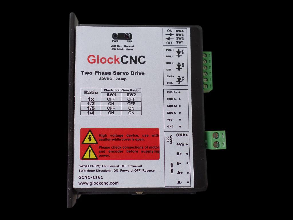
3 Key Features Smooth and quiet operation at all speeds and extremely low motor heating Industrial grade performance for an alternating current servo motor Field oriented control based low voltage servo loop Fully configurable position and velocity loop Input supply voltage from 18VDc to 80VDC Delivers up to 7amps of continuous current Selectable gear-ratio for encoder with counts from 4000 to per revolution PULSE, DIRECTION and ENABLE inputs with opto-isolated interface Short-circuit protection for the motor outputs, over-voltage and under-voltage protection LED indication for power and error states Description Thank you for purchasing GCNC-1110, Hybrid AC Driver. GCNC-1110 is GlockCNC introductory hybrid low voltage AC drive designed for smooth and quiet operation without compromising on torque and control at higher speeds. It has short-circuit protection for the motor outputs, over-voltage and under-voltage protection and will survive accidental motor disconnects while powered-up. The GCNC-1110 delivers a low-voltage servo performance using a field oriented control (FOC) current loop for two-phase hybrid PMSM motors. It also provides a fully configurable position and velocity loop with feed-forward variables to achieve close to zero lag in servo performance. Two phase PMSM servo systems give an advantage of higher speed, faster response and very low motor heating. The GCNC-1110 s FOC control gains are calibrated on start-up based on motor characteristics and also adjusted dynamically while the motor is in motion. This control algorithm makes it capable of achieving better torque at higher speeds in comparison to comparable drives in its range. The PULSE/STEP, DIRECTION and ENABLE inputs are optically isolated. Both inputs work with 2.5V, 3.3V or 5V logic drive signals. The input drive current is 5mA at 2.5V so almost all logic family (74LS, 74HC, etc.) can be used to drive these inputs. The GCNC-1110 hybrid AC drive is warranted to be free of manufacturing defects for six months from the date of purchase. Please see the section on service, support and warranty at the end of this document. Page 3
4 Technical Specifications Specification Min Max Units Comments Supply Voltage Volts DC Between +Ve and GND Phase Current Amps As demanded by load Servo Loop Speed Hz Power Dissipation 0 15 Watts Short-Circuit Current 7 10 Amps In case of motor terminal short PUL and DIR Voltage Volts DC Between + and input pins Ambient Temp Celsius Humidity 0 95% Non condensing Step Frequency 200 khz Direction Setup time 500 ns Steps is clocked on positive edge Mechanical Specifications Specification Dimensions (L * W * H) Weight Heat Sink Mounting Screw Holes Details 110mm * 77mm *33mm 155gms Anodized Aluminum 3mm thickness 3.6mm minimum diameter Caution Read this document carefully before installing and using you drive Inputs voltage to the drive must not exceed the maximum of 80VDC or it may damage the drive Reversing polarity power supplied to the drive will damage the drive or power supply Connecting the power supply wires to the terminals outputs of the motor coils will damage the drive Short-circuiting the motor terminals to +Ve power or to each other or to GND may damage the drive Excess humidity or condensation on the drive may damage the drive Voltage in excess of 7V between the PULSE+ and PULSE- or DIR+ and DIR- or ENA+ and ENAinput terminals may damage the opto-isolators Reverse voltage in excess of 7V between the PULSE- and PULSE+ or DIR- and DIR+ or ENA+ and ENA- input terminals may damage the opto-isolators Heat sink is designed to dissipate heat from the drive circuitry as long as the ambient temperature is less that 70 degrees Celsius. Ambient temperature in excess of that may damage the drive Do not un-plug the terminals of the motor while the drive is powered up and running Page 4
5 Power and Motor Terminal Assignments Terminal No. Terminal Name Description Terminal 1 A- Motor Coil Phase A- Terminal 2 A+ Motor Coil Phase A+ Terminal 3 B- Motor Coil Phase B- Terminal 4 B+ Motor Coil Phase B+ Terminal 5 +V Power +Ve (18VDC to 80VDC Max wrt. GND) Terminal 6 GND Power Ground or Power Ve Encoder Terminal Assignments Terminal No. Terminal Name Wire Colour Description Terminal 1 GND BLACK Power Ground or Power Ve Terminal 2 +V RED Power +Ve (5VDC wrt. GND) Terminal 3 A- GREEN Motor Coil Phase A- Terminal 4 A+ YELLOW Motor Coil Phase A+ Terminal 5 B- WHITE Motor Coil Phase B- Terminal 6 B+ BLUE Motor Coil Phase B+ Pulse and Direction Input Assignments Terminal No. Terminal Name Description Terminal 1 ENA- Enable (Motor Free) -Ve optically isolated input Terminal 2 ENA+ Enable (Motor Free) +Ve optically isolated input Terminal 3 DIR- Direction -Ve optically isolated input Terminal 4 DIR+ Direction +Ve optically isolated input Terminal 5 PUL- Pulse -Ve optically isolated input Terminal 6 PUL+ Pulse +Ve optically isolated input Switch Selection Table for Step Selection Resolution SW1 SW2 1/4 ON ON 1/5 OFF ON 1/2 ON OFF 1x OFF OFF Page 5
6 Switch (3): Sets EEPROM permissions SW3 ON EEPROM Data Locked SW3 OFF EEPROM Data Unlocked Switch (4): Sets Direction SW4 ON Forward Direction SW4 OFF Reverse Direction RS-232 command port A 4pin command port is available on the drive for debug and tuning routines. This port is accessible on the main drive board after opening the drive cover. The communication setting are given below along with a command list. A cable for connecting a RS-232 DB9 to the port is usually shipped with the drive. After connecting it to a computer the drive can be accessed by simple commands using any terminal software. The baud rate of bps is default with no flow control, 8 bit data and 1 stop bit. The below list of commands can be used to read or write a register. A new line and carriage return is required to process any command. Command and Register Table Command List Register Description Default Max A Position Proportional Gain B Velocity Proportional Gain C Velocity Integral Gain D Velocity Damping E No. of Poles in Motor Construction F Encoder Counts Per Revolution G Current Loop P-Gain H Current Limit I Position Error Limit J Current Loop I-Gain K Acceleration Feed-Forward L Home Position in Counts 0 0 N Velocity Feed-Forward O Position Integral Gain R LED Trigger Level for Current Page 6
7 Additional Commands Command List Description Default Max P Go To Absolute Position 0 +/ M Go To Relative Position 0 +/ S Start Data Stream 0 T Stop Data Stream 0 a Go to Acceleration and Deceleration s Go to Velocity Setting Q Input Multiplier 1 8 X Set Defaults Y Save to EEPROM Power Supply Selection The general rule of thumb to get the most out of the motor is to drive it with a supply voltage that is atleast 3 to 4 times its rated supply voltage. A DC regulated power supply with good low-esr decoupling capacitors on its output is recommended for best performance of this drive. LED Status and Error Codes There is a single LED on this drive for power and error status messages. In case the LED is blinking or flickering please check all connections and powered-down, wait for 5 seconds and then power-up the drive once again. LED State Green LED ON and steady Red LED Flickering randomly Red LED blinking Message Powered up and calibrated Current Trigger Level Achieved Short circuit on motor terminals or drive message to connection error Guide to General Problems Problem Symptom Motor is not rotating Possible Reasons and Solutions Drive is not powered up Motor is not connected properly to the drive Drive is in an error state, check LED status Pulse and Direction inputs are not connected properly or are not supplying enough current Page 7
8 Motor rotates in the wrong direction LED is blinking Drive is not powering up (no LED) Erratic Motion on Motor Motor stalls during accelerating Excessive Motor or Drive Heating Motor Phase connections may be reversed Check LED status messages in this document and check connections and voltages accordingly Drive might be damaged due to incorrect installation or handling Check that the connectors to the drive are tightly plugged in Check the supply voltage is adequate and in correct polarity Drive might be damaged due to incorrect installation or handling Power supply voltage not stable or regulated Motor Coil damaged or not connected to the drive correctly Current setting on the motor too high Control signals of Pulse or Direction are not connected properly or not supplying enough voltage and current Control signal interference due to power supply or environmental noise Motor load is too high Acceleration is too high Gain settings is too low of the Motor Power Supply is too low for Motor or Speed Drive is damaged Power supply voltage is too high Not enough cooling or ventilation for motor or drive Control Signal Connection NPN pull-down In this connection technique all the signal +ve inputs are connected to a common high voltage VCC. The opto-isolators LED is turned on by a pull-down on the Ve terminals by an NPN-transistor output Page 8
9 Control Signal Connection PNP pull-up In this connection technique all the signal -ve inputs are connected to a common low voltage GND. The opto-isolators LED is turned on by a pull-up on the +Ve terminals by an PNP-transistor output Control Signal Connection Differential In this connection technique each input is differential controlled and no necessity for a common voltage Page 9
10 2-phase, 4-lead Motors Connections 4 lead motors are the least flexible but easiest to wire. Speed and torque will depend on winding inductance. In setting the drive output current, multiply the specified phase current by 1.4 to determine the peak output current. Page 10
11 Service and Support Service and support for this product are available from the GlockCNC Web site () and our customer service 90 Day Warranty GlockCNC (glockcnc.com) warrants its products against defects in materials and workmanship for a period of 90 days from shipment delivery. During the warranty period, GlockCNC will either, at its option, repair or replace products which proved to be defective. Exclusions The above warranty does not extend to any product damaged by reasons of improper or inadequate handling by customer, improper or inadequate customer wiring, unauthorized modification or misuse, or operation beyond the electrical specifications of the product and/or operation beyond environmental specifications for the product. Obtaining Warranty Service To obtain warranty service, please contact our customer service department at sales@glockcnc.com before returning product for service. Please make sure that you have gone through this entire installation manual and datasheet before deciding that your product is liable for replacement or repair under this 90 day warranty Customer shall prepay shipping charges for products returned to GlockCNC for warranty service, and GlockCNC shall pay for return of products to customer. All foreign warranty work will be shipped back with the buyer paying half of the shipping costs. Warranty Limitations GlockCNC makes no other warranty, either expressed or implied, with respect to the product. GlockCNC specifically disclaims the implied warranties of merchantability and fitness for a particular purpose. Some jurisdictions do not allow limitations on how long and implied warranty lasts, so the above limitation or exclusion may not apply to you. However, any implied warranty of merchantability or fitness is limited to the 90 day duration of this written warranty. Disclaimer Copyright GlockCNC, 2017 Neither the whole nor any part of the information contained in, or the product described in this manual, may be adapted or reproduced in any material or electronic form without the prior written consent of the copyright holder. This product and its documentation are supplied on an as-is basis and no warranty as to their suitability for any particular purpose is either made or implied. This document provides preliminary information that may be subject to change without notice. Page 11
RHINO MOTION CONTROLS RMCS-1120 Hybrid Servo Driver with Modbus RTU communication (Max. 50Vdc and 7A per phase)
") Installation Manual and Datasheet Page 1 Key Features Smooth and quiet operation at all speeds and extremely low motor heating Industrial grade performance for an alternating current servo motor Field
Installation Manual and Datasheet Page 1 Key Features Smooth and quiet operation at all speeds and extremely low motor heating Industrial grade performance for an alternating current servo motor Field
PSR5042. Stepper Motor Drive User s Manual. Version 1.0. Contacts: Technical support: Sales information:
 This manual contains reserved and proprietary information. All rights are reserved. It may not be copied, disclosed or used for any purposes not expressly authorized by PrimoPal Motor. PrimoPal Motor reserves
Change Log by Leadshine Technology, All Rights Reserved
 Hardware Installation Manual for EM Series Stepper Drives www.leadshine.com NTS-HWMN-EM-R2011101 ii Leadshine reserves the right to make changes without further notice to any products herein to improve
Hardware Installation Manual Integrated BLDC Servo Motor
 Hardware Installation Manual Integrated BLDC Servo Motor Version 1.0.0 http://www.leadshine.com Safety Items! Caution Make sure the power supply voltage dose not exceed the drive s input range. Double
ii Leadshine reserves the right to make changes without further notice to any products herein to improve reliability, function or design. Leadshine do
 Hardware Installation Manual for EM Series Stepper Drives www.leadshine.com ii Leadshine reserves the right to make changes without further notice to any products herein to improve reliability, function
Hardware Manual of Easy Servo Drives ES-D Series
 Hardware Manual of Easy Servo Drives ES-D Series Version 0.1.0 http://www.leadshine.com ii Safety Items! Notice Read this manual carefully before trying to install the stepper drive into your system. The
Hardware Installation Manual
 Hardware Installation Manual Of the Easy servo Drives Version 0.0.1 http://www.leadshine.com ii Safety Items! Notice Read this manual carefully before trying to install the stepper drive into your system.
PSR3015. Stepper Motor Drive User s Manual. Version 1.0. Contacts: Technical support: Sales information:
 This manual contains reserved and proprietary information. All rights are reserved. It may not be copied, disclosed or used for any purposes not expressly authorized by PrimoPal Motor. PrimoPal Motor reserves
User Manual of 3M583
 ECG-SAVEBASE EMAIL:EBAY@SAVEBASE.COM WEB: HTTP://STORES.EBAY.CO.UK/SAVEBASE User Manual of 3M583 High Performance Microstepping Driver ECG-SAVEBASE ECG Safety Statement Easy Commercial Global is not liable
User Manual CL57T. Closed Loop Stepper Drive.
 User Manual CL57T Closed Loop Stepper Drive Notice Read this manual carefully before any assembling and using. Incorrect handling of products in this manual can result in injury and damage to persons and
User s Manual. Extremely Low Noise 3-phase Microstepping Driver. For 3L583M. Version All Rights Reserved
 User s Manual For Extremely Low Noise 3-phase Microstepping Driver Version 1.0 2008 All Rights Reserved Attention: Please read this manual carefully before using the driver! The content in this manual
User Manual For DM332T. 2-Phase Digital Stepper Drive. Designed by StepperOnline. Manufactured by Leadshine
 User Manual For DM332T 2-Phase Digital Stepper Drive Designed by StepperOnline Manufactured by Leadshine #7 Zhongke Road, Jiangning, Nanjing, China T: 0086-2587156578 Web site: www.omc-stepperonline.com
User Manual DM556T. 2 Phase Digital Stepper Drive. Designed by StepperOnline Manufactured by Leadshine 2017 All Rights Reserved
 User Manual DM556T 2 Phase Digital Stepper Drive Designed by StepperOnline Manufactured by Leadshine 2017 All Rights Reserved Address: #7 Zhongke Road, Jiangning, Nanjing, China Tel: 0086-2587156578 Web:
DM542E. User Manual. 2 Phase Digital Stepper Drive Leadshine Technology Co., Ltd. Revision 1.0
 User Manual DM542E 2 Phase Digital Stepper Drive Revision 1.0 2016 Leadshine Technology Co., Ltd. Leadshine Technology Co., Ltd (Headquarters) Address: Floor 11, Block A3, ipark 1001 Xueyuan Avenue Shenzhen,
ADVANCED MICRO SYSTEMS
 Overview... 3 Included in the Box:... 3 Pinout... 4 Installation... 5 Power Supply... 6 Stepping Motors... 7 DIP Switch (JP1) Location... 8 Setting the Output Current (JP1)... 8 Microstep Resolution (JP1)...
Overview Included in the Box: Pinout Installation Power Supply Stepping Motors DIP Switch (JP1) Location...
 Location...") DRV7 USERS GUIDE Overview... 3 Included in the Box:... 4 Pinout... 4 Installation... 5 Power Supply... 6 Stepping Motors... 8 DIP Switch (JP1) Location... 9 Setting the Output Current (JP1)... 9 Microstep
DRV7 USERS GUIDE Overview... 3 Included in the Box:... 4 Pinout... 4 Installation... 5 Power Supply... 6 Stepping Motors... 8 DIP Switch (JP1) Location... 9 Setting the Output Current (JP1)... 9 Microstep
MD3. Microstepping Motor Driver Page 1 of 7. Description. Software. Mechanical Drawing. Features
 Page 1 of 7 The MD3 is a stepper motor driver with an integrated motion controller that is capable of driving size 14 to 42 stepper motors from 2 to 256 microsteps per step. Peak motor currents are selectable
EM806 2-phase Digital Stepper Drive
 EM806 2-phase Digital Stepper Drive 24-80V, 0.35-6A, Sensorless Stall Detection, Pre-Matching Motor Sensorless stall detection eliminates cost of feedback devices and time of cable connection Super-low
D115 The Fast Optimal Servo Amplifier For Brush, Brushless, Voice Coil Servo Motors
 D115 The Fast Optimal Servo Amplifier For Brush, Brushless, Voice Coil Servo Motors Ron Boe 5/15/2014 This user guide details the servo drives capabilities and physical interfaces. Users will be able to
EM705 2-phase Digital Stepper Drive
 EM705 2-phase Digital Stepper Drive 20-70V, 0.35-5A, Sensorless Stall Detection, Pre-Matching Motor Sensorless stall detection eliminates cost of feedback devices and time of cable connection Super-low
G540 User Manual. Date Modified: March 5, 2012 Page 1 of 10
 G540 User Manual Date Modified: March 5, 2012 Page 1 of 10 DIMENSIONS PHYSICAL AND ELECTRICAL RATINGS Minimum Maximum Units Supply Voltage 18 50 VDC Motor Current 0 3.5 A Power Dissipation 1 13 W Short
G540 MANUAL MULTIAXIS STEP MOTOR DRIVE
 G540 MANUAL MULTIAXIS STEP MOTOR DRIVE PRODUCT DIMENSIONS PHYSICAL AND ELECTRICAL RATINGS Minimum Maximum Units Supply Voltage 18 50 VDC Motor Current 0 3.5 A Power Dissipation 1 13 W Short Circuit Trip
Integrated Stepper Drive & Motor
 SMD23 Integrated Stepper Drive & Motor Manual #: 940-0S050 User Manual AMCI Motion Control Products Important User Information The products and application data described in this manual are useful in a
Datasheet-MA860 Stepper Motor Driver
 Datasheet-MA860 Stepper Motor Driver Introduction The MA860 is an economical micro-stepping driver based on patented technology of EDRIVE. It is suitable for driving 2-phase and 4-phase hybrid stepping
FEATURES: DESCRIPTION: APPLICATIONS: SPECIFICATIONS: Electrical Specifications of Drive: Operating Environment: [Geben Sie Text ein]
![FEATURES: DESCRIPTION: APPLICATIONS: SPECIFICATIONS: Electrical Specifications of Drive: Operating Environment: [Geben Sie Text ein]](/thumbs/93/111844613.jpg "FEATURES: DESCRIPTION: APPLICATIONS: SPECIFICATIONS: Electrical Specifications of Drive: Operating Environment: [Geben Sie Text ein]") ist-09 ist-0 FEATURES: Integrated compact size for saving mounting space & setup time, and reducing electrical interference Anti-Resonance provides optimal torque and nulls mid-range instability Motor
ist-09 ist-0 FEATURES: Integrated compact size for saving mounting space & setup time, and reducing electrical interference Anti-Resonance provides optimal torque and nulls mid-range instability Motor
EM556S Digital Stepper Drive User Manual. User Manual EM556S. Digital Stepper Drive. Revision All Rights Reserved
 User Manual EM556S Digital Stepper Drive Revision 1.0 2017 All Rights Reserved Important Notice Read this manual carefully before any assembling and using. Incorrect handling of products in this manual
PMDX-108-Output. 8-Channel Isolated Output Board for PC parallel port pins 2-9. User s Manual
 PMDX-108-Output 8-Channel Isolated Output Board for PC parallel port pins 2-9 User s Manual Date: 25 February 2010 PMDX Web: http://www.pmdx.com 9704-D Gunston Cove Rd Phone: +1 (703) 372-2975 Lorton,
G540 4-AXIS DRIVE REV 4: MAY 28, 2010
 Thank you for choosing to purchase the G540 4-Axis Drive System. If you are dissatisfied with it for any reason at all within two weeks of its purchase date, you may return it for a full refund provided
The SilverNugget is a servo controller/driver for NEMA 17 & 23 frame microstep motors.
 Date: 5 November 2008 www.quicksilvercontrols.com SilverNugget N2 M-Grade The SilverNugget is a servo controller/driver for NEMA 17 & 23 frame microstep motors. Property of Page 1 of 13 This document is
Hardware Installation Manual MX Axis Stepper Drive with Breakout Board & I/O s
 Hardware Installation Manual MX3660 3-Axis Stepper Drive with Breakout Board & I/O s Version 1.0 11 / 2013 Hardware Manual for MX3660 3-Axis Stepper Drive with Breakout Board & I/O s ii Notice Read this
R325P Single Axis Driver
 R325P Single Axis Driver User Manual And Commands Guide Version 1.3 Thank you for purchasing the R325P Single-Axis Step & Direction Driver. This product is warranted to be free of manufacturing defects
CS-D508. User Manual. Closed Loop Stepper Drive Leadshine Technology Co., Ltd. Revision 3.1
 User Manual CS-D508 Closed Loop Stepper Drive CS-D508 Closed Loop Stepper Drive User Manual Version 3.1 Revision 3.1 2018 Leadshine Technology Co., Ltd. Leadshine Technology Co., Ltd (Headquarters) Address:
KL1108 Closed Loop Stepping System
 KL1108 Closed Loop Stepping System 1. Introduction Descriptions KL1108 is a new generation hybrid servo driver, it combines the advantage of both the servo system and stepper system,the system acts as
SMD Series Integrated Stepper Driver and Motor Revision 1.3
 The AMCI Integrated Stepper Motor and Microstepping Drive Combination represents the future of Stepper Motor Control applications. The SMD is a self-contained stepper motor and driver package, capable
Users Manual. For P808. High Performance Microstepping Driver
 Users Manual For P808 High Performance Microstepping Driver Thank you for purchasing the Astrosyn P808 drive. Please read this manual thoroughly before installing and operating the driver, and always keep
PMDX-103. Parallel Port Isolator Board. User s Manual. Document Revision: 1.2 Date: 20 February 2007 PCB Revision: PCB-447B
 PMDX-103 Parallel Port Isolator Board User s Manual Date: 20 February 2007 PMDX Web: http://www.pmdx.com 9704-D Gunston Cove Rd Phone: +1 (703) 372-2975 Lorton, VA 22079-2366 USA FAX: +1 (703) 372-2977
MSD325 Microstepping Drive
 MSD325 Microstepping Drive Introduction MSD325 is a very small size microstepping drive based on most advanced technology in the world today. It is suitable for driving any 2-phase and 4-phase hybrid stepper
TECHNICAL REFERENCE BSD V-3A Bipolar Stepper Driver
 TECHNICAL REFERENCE BSD 3630 36V-3A Bipolar Stepper Driver Contents Chapter 1 Safety Precautions.. 3 Chapter 2 Drive Overview...4 2.1 Key Features...4 2.2 Drive Description...4 2.3 Applications. 4 Chapter
The SilverNugget is a servo controller/driver for NEMA 34 frame microstep motors.
 Date: 25 July 2008 www.quicksilvercontrols.com SilverNugget N3 M-Grade The SilverNugget is a servo controller/driver for NEMA 34 frame microstep motors. Property of Page 1 of 13 This document is subject
HARDWARE MANUAL TMCM-1613 TMCM-1613-REC. Hardware Version V TRINAMIC Motion Control GmbH & Co. KG Hamburg, Germany.
 MODULES FOR BLDC MOTORS MODULES Hardware Version V 1.10 HARDWARE MANUAL + + TMCM-1613 + + Single Axis BLDC Controller / Driver Block-commutation Hall-sensor based Analog+digital inputs / outputs Up-to
MSD980 Microstepping Drive
 MSD980 Microstepping Drive Introduction MSD980 is a high-performance microstepping drive based on most advanced technology in the world today. It is suitable for driving any 2-phase and 4-phase hybrid
TB6600 Stepper Motor Driver
 TB6600 Stepper Motor Driver V1.0 07 2018 Open Source Mechatronics LTD 2018 Safety Statement The author of this document is not liable or responsible for any accidents, injuries, equipment damage, property
HARDWARE MANUAL TMCM-1613 TMCM-1613-REC. Hardware Version V TRINAMIC Motion Control GmbH & Co. KG Hamburg, Germany.
 MODULES FOR STEPPER MOTORS MODULES Hardware Version V 1.10 HARDWARE MANUAL + + TMCM-1613 + + Single Axis BLDC Controller / Driver Block-commutation Hall-sensor based Analog+digital inputs / outputs Up-to
Version 1.9. Reference for Part Numbers: EQUBE-P EQUBE-N EQUBE-AI-P
 Version 1.9 January 2018 Reference for Part Numbers: EQUBE-P EQUBE-N EQUBE-AI-P Publication EQ-1000 Module firmware and functionality is protected by U.S. and international patents. For complete patent
Hardware Manual 1240i-485
 Hardware Manual -485 Intelligent Step Motor Driver with Multi-drop RS-485 Interface 920-0033 A 7/6/2010 motors drives controls -2- Table of Contents Introduction...4 Features...4 Block Diagram...4 Getting
2L415B High Performance-Cost ratio 2-phase Microstepping Driver
 User s Manual High Performance-Cost ratio 2-phase Microstepping Driver VER 2.0 Appreciate your selection of MotionKing TM driver. To make full use of its versatile performance, please read this manual
KL-8056D. Table of Contents. Fully Digital Stepping Driver
 Contents KL-8056D Fully Digital Stepping Driver Attention: Please read this manual carefully before using the driver! Table of Contents 1. Introduction, Features and Applications...1 Introduction...1 Features...1
Brushless DC Motor Driver CBM-105 FN/FP User Manual
 Brushless DC Motor Driver CBM-105 FN/FP User Manual Thank you for purchasing an Itoh Denki CBM-105 series motor driver. Please read this manual before operating the product, and keep this manual readily
PMDX-105. I/O Option Riser Board User s Manual. Document Revision: 1.1 Date: 7 September 2004 PCB Revision: PCB-443A
 PMDX-105 I/O Option Riser Board User s Manual Date: 7 September 2004 PMDX Web: http://www.pmdx.com 7432 Alban Station Blvd., A105 Phone: +1 (703) 912-4991 Springfield, VA 22150-2321 USA FAX: +1 (703) 912-5849
STEP MOTOR DRIVER SMD-4.2DIN
 SMART MOTOR DEVICES http://www.smd.ee STEP MOTOR DRIVER SMD-4.2DIN manual SMDDIN.42.001 2018 1. Product designation Step motor controller SMD-4.2DIN is an electronic device designed to operate with 2 or
PMDX-170 Slotted Optical Sensor
 PMDX-170 Slotted Optical Sensor User s Manual Date: 20 May 2009 PMDX Web: http://www.pmdx.com 9704-D Gunston Cove Rd Phone: +1 (703) 372-2975 Lorton, VA 22079-2366 USA FAX: +1 (703) 372-2977 PMDX-170_Manual_10.doc
A range of brushless servo drives with optional controllers
 SV-S & SVHX-S series servo drives A range of brushless servo drives with optional controllers SV-S and SVHX-S Series intelligent servo drives combine advanced microprocessor control with established analogue
Resolver to Digital Expansion Board
 Resolver to Digital Expansion Board Catalog No. EXB009A01 Installation and Operating Manual 6/98 MN1313 Table of Contents Section 1 General Information............................. 1-1 Introduction....................................
EE-SX97 40% Built-in connector enables downsizing and easier connection. Protective circuit for safe operation. Slot-type Photomicrosensor.
 Slot-type Photomicrosensor EE-SX CSM_EE-SX_DS_E Built-in connector enables downsizing and easier connection. Protective circuit for safe operation. A built-in connector minimizes the shape and dimensional
RoboClaw 120A/160A/200A Dual Channel Motor Controller
 RoboClaw 2x160A, 34VDC Dual Channel RoboClaw 2x120AHV, 60VDC Dual Channel RoboClaw 2x160AHV, 60VDC Dual Channel RoboClaw 2x200AHV, 60VDC Dual Channel Brushed DC Motor Controllers Version 2.1 (c) 2016 Ion
RoboClaw 2x30A Dual Channel Motor Controller
 RoboClaw 2x30A, 34VDC Dual Channel Brushed DC Motor Controller Version 2.2 (c) 2016 Ion Motion Control. All Rights Reserved. Feature Overview: 60 Amps Peak Per Channel Channel Bridging Supported Dual Quadrature
Industrial Ethernet Ethernet to Serial Gateways Ethernet to Serial Converters for Modbus, Red lion and other protocols
 USER MANUAL Industrial Ethernet Ethernet to Serial Gateways Ethernet to Serial Converters for Modbus, Red lion and other protocols Contents at a Glance: Section 1 General Information RM-PS-024-01F 3 Section
The information in this chapter will enable you to:
 C H A P T E R ➅ Hardware Reference The information in this chapter will enable you to: Environmental Specifications Use this chapter as a quick reference tool for most system specifications Use this chapter
Contents. HP E1586A Rack Mount Terminal Panel User s Manual
 Contents HP E1586A Rack Mount Terminal Panel User s Manual Description... 5 Connecting to VXIbus Instruments... 5 Interconnect Cables... 5 Terminal Block Connections... 6 Using the Terminal Panel for Reference
PLC-24V10AL(-PT/-TH) Quick Start Manual (Rev.1.10)
 Quick Start Manual (Rev.1.10)") TEC (Peltier) Controller PLC-24V10AL(-PT/-TH) Quick Start Manual (Rev.1.10) Thank you for purchasing the TEC (Peltier) Controller PLC-24V10AL. Read these operating instructions carefully to ensure effective
TEC (Peltier) Controller PLC-24V10AL(-PT/-TH) Quick Start Manual (Rev.1.10) Thank you for purchasing the TEC (Peltier) Controller PLC-24V10AL. Read these operating instructions carefully to ensure effective
V E1B Snap-in I/O Module
 V200-18-E1B Snap-in I/O Module The V200-18-E1B plugs directly into the back of compatible Unitronics OPLCs, creating a selfcontained PLC unit with a local I/O configuration. Features 16 isolated digital
Model NPN output PNP output Standard. configuration
 Slot-type Photomicrosensor (Non-modulated) *1 EE-SX4/6 CSM_EE-SX4_6_DS_E 1 Global Standard Slot-type photomicrosensors with 0- to 100-mA direct switching capacity. Series includes models that enable switching
Digital Lighting Systems, Inc. PD216. Two Channel Dimmer and Switch Packs PROTOCOL USER'S MANUAL. PD216-UM Rev. E - 02/03
 Digital Lighting Systems, Inc. PD26 Two Channel Dimmer and Switch Packs PROTOCOL PD26 S2 S USER'S MANUAL PD26-UM Rev. E - 02/03 Digital Lighting Systems PD26 User's Manual - Page GENERAL DESCRIPTION The
SCHOTT FLM 4 Fiber Lighting Modul. Operating Instructions
 SCHOTT FLM 4 Fiber Lighting Modul Operating Instructions Contents 1. Important information 3 2. Scope of Delivery 3 3. Intended use 3 4. Safety information 4 5. Operation 5 5.1. LED Optics Module 5 5.2.
PCL451. Manual Preset Indexer. User s Guide E Landon Drive, Anaheim, CA
 PCL451 Manual Preset Indexer User s Guide A N A H E I M A U T O M A T I O N 4985 E Landon Drive, Anaheim, CA 92807 e-mail: info@anaheimautomation.com (714) 992-6990 fax: (714) 992-0471 website: www.anaheimautomation.com
E2EY. A Proximity Sensor for Aluminum, Brass and Other Non-ferrous Metals. Iron Is Not Detected. Aluminum-detecting Proximity Sensor
 Aluminum-detecting Proximity Sensor EEY CSM_EEY_DS_E_5_1 A Proximity Sensor for Aluminum, Brass and Other Non-ferrous Metals. Iron Is Not Detected. Non-ferrous metals, such as aluminum and brass, are detected.
The SilverNugget is a servo controller/driver for NEMA 17 & 23 frame microstep motors.
 Date: 5 November 2008 www.quicksilvercontrols.com SilverNugget N2 I-Grade The SilverNugget is a servo controller/driver for NEMA 17 & 23 frame microstep motors. Property of Page 1 of 10 This document is
Expansion Unit Catalog Nos , - 152, - 153, - 154, - 156, -E157
 PRODUCT DA TA SLC 150 110 Expansion Unit Catalog Nos. 1745-151, - 152, - 153, - 154, - 156, -E157 7 : The EXpdnSiQn Unit The SLC 150 expansion unit can be used with either the SLC 150 processor unit or
STATUS Shiloh Road Alpharetta, Georgia (770) FAX (770) Toll Free
 FAX (770) Toll Free") Instruction Manual Model 1582-45L Data Switch September 2010, Rev A REMOTE LOCAL SWITCH STATUS SELECT REMOTE LOCAL LOCAL SELECT CHANNEL SELECT POWER MODEL 1582 SWITCH CROSS TECHNOLOGIES, INC. Data, drawings,
Instruction Manual Model 1582-45L Data Switch September 2010, Rev A REMOTE LOCAL SWITCH STATUS SELECT REMOTE LOCAL LOCAL SELECT CHANNEL SELECT POWER MODEL 1582 SWITCH CROSS TECHNOLOGIES, INC. Data, drawings,
Digital Lighting Systems, Inc.
 , Inc. PD402-DMX Four Channel Dimmer and Switch Packs 4 x 2.5 Amps @ 6VDC to 24 VDC DMX52 compatible DMX52 4 x 2.5 Amps Dimmer Pack C UL US LISTED Digital Lighting Systems, Inc. USER'S MANUAL User's Manual
User Guide. Control Box. RoscoLED TM.
 RoscoLED TM Control Box User Guide This guide applies to the following RoscoLED Control Box models: RoscoLED Control Box 300W/Static White (293 22250 0000) RoscoLED Control Box 400W/VariWhite (293 22260
Model NPN output PNP output Standard. configuration
 Slot-type Photomicrosensor (Non-modulated) *1 EE-SX/6 CSM_EE-SX/6_DS_E_1_ Global Standard Slot-type photomicrosensors with 0- to 100-mA direct switching capacity. Series includes that enable switching
INSTRUCTION MANUAL. Model True RMS AC/DC 30A Mini Clamp-on Meter. Introduction. True RMS AC Current and Voltage
 INSTRUCTION MANUAL Model 380942 True RMS AC/DC 30A Mini Clamp-on Meter True RMS AC Current and Voltage Measure low current with high resolution to 0.1mA AC and 1mA DC Auto Power Off One touch DCA zero
Stepper motor driver HEM-545 last change:
 Documentation for Stepper motor driver HEM-545 last change: 16.03.2011 Functional description HEM-545 is a one channel motor driver for 2-phase stepping motors with pulse and direction interface. Motor
E2K-F. Flat Capacitive Sensor with a Thickness of Only 10 mm. Flat Proximity Sensor. Ordering Information. Sensors [Refer to Dimensions on page 4.
 Flat Proximity Sensor EK-F CSM_EK-F_DS_E Flat Capacitive Sensor with a Thickness of Only mm Flat Sensor with excellent space efficiency. (Model with built-in Amplifier is only mm thick.) Direct mounting
Si 2035 Programmable Stepper Drive
 Si 23 Programmable Stepper Drive Description The Si23 is a programmable stepper drive/ indexer packaged in a rugged steel case. Integral heat sink, mounting brackets, switch covers and connectors are included
User's Guide. Model High Precision Quad Output DC Power Supply
 User's Guide Model 382270 High Precision Quad Output DC Power Supply Introduction Congratulations on your purchase of the Extech 382270 DC Power Supply. The Model 382270 can be used for many applications
User Manual. UIM240XX Series Parallel Signal Control Miniature Integrated Stepper Motor Driver
 User Manual UIM240XX Series Parallel Signal Control Miniature Integrated Stepper Motor Driver UIM24002/04/08 Please pay attention to the following before using the UIROBOT products: UIROBOT products meet
E2KQ-X. Fluororesin-coated Capacitive Sensor with Sensitivity Adjuster. Chemical-resistant Proximity Sensor. Ordering Information
 Chemical-resistant Proximity Sensor E2KQ-X CSM_E2KQ-X_DS_E_4_3 Fluororesin-coated Capacitive Sensor with Sensitivity Adjuster Excellent resistance against chemicals and oil with fluororesincoated case.
Advanced Features. High Performance Stepper Drive Description. Self Test and Auto Setup
 www.applied-motion.com STAC6 High Performance Stepper Drive Description The STAC6 represents the latest developments in stepper drive technology, incorporating features that will derive the highest performance
SERVO-DRIVE. PROGRAMMABLE STEP MOTOR CONTROLLER R ETH and R ETH. Manual Ver. 05
 SERVO-DRIVE PROGRAMMABLE STEP MOTOR CONTROLLER R272-42-ETH and R272-80-ETH Manual Ver. 05 2018 1. Product designation Programmable step motor controller R272-42-ETH is designed to operate with hybrid two
THE CTB08D LIGHT CONTOLLER
 THE CTB08D LIGHT CONTOLLER The CTB08D is a one of the components in the Hobbyist line of Light- O-Rama products. The CTB08D must be used in conjunction with the Light-O-Rama software package. This controller
DG2S series. User s Manual and Installation Guide. DC Servo drive. Contents. 1. Safety, policy and warranty.
 DG2S series DC Servo drive User s Manual and Installation Guide Contents 1. Safety, policy and warranty. 1.1. Safety notes. 1.2. Policy. 1.3. Warranty. 2. Electric specifications. 2.1.Operation ranges.
DMX-K-DRV Integrated Step Motor Driver Manual
 Tu Sitio de Automatización! DMX-K-DRV Integrated Step Motor Driver Manual Table of Contents 1. Introduction... 4 2. Part Numbering Scheme... 4 3. Dimensions... 5 NEMA 11 DMX-K-DRV... 5 NEMA 17 DMX-K-DRV...
PD Series. packaged ministep drives. A range of universal ministep drives including fully EMCcompliant. Automation. PD series general features
 packaged ministep drives range of universal ministep drives including fully EMCcompliant versions The, featuring 4-step/rev resolution and a universal 'go anywhere' power supply, comprises four basic models
EASON TECHNOLOGY. IO8 & IO24 Break-Out Module
 EASON TECHNOLOGY IO8 & IO24 Break-Out Module p/n 50-00180-01 Revision1.2 Eason Technology, Inc. 7975 Cameron Dr. Bldg 300 Windsor, CA 95492 Phone (707) 837-0120 FAX (707) 837-2742 http://www.eason.com
SUM-40 OPERATING MANUAL. Ma0 DYNAMIC STRUCTURES AND MATERIALS, LLC REV
 Ma0 SUM-40 OPERATING MANUAL DYNAMIC STRUCTURES AND MATERIALS, LLC REV. 171011 Please review the following points for both personal and equipment safety while operating the SUM-40 motor. HIGH ENERGY/VOLTAGE
KL-4042D Fully Digital Stepping Drive
 KL-4042D Fully Digital Stepping Drive Version 1.0 2010 All Rights Reserved Attention: Please read this manual carefully before using the drive! Table of Contents 1. Introduction, Features and Applications...
USER S MANUAL VER.1. C10D- PARALLEL PORT INTERFACE CARD BOARD Rev. 1
 USER S MANUAL VER.1 C10D- PARALLEL PORT INTERFACE CARD BOARD Rev. 1 MARCH 2018 User s Manual Page i USER'S MANUAL TABLE OF CONTENTS Contents Page # 1.0 OVERVIEW... iii 2.0 FEATURES... iii 3.0 SPECIFICATIONS...
Thermoelectric Cooler Controller TED1000
 Thermoelectric Cooler Controller TED1000 Operating Instructions MANUAL-TED1000-1.0 Aug 2015 Rev.1 2 Contents 1 General... 4 1.1 Warranty and Assistance... 4 1.2 Maintenance... 4 1.3 General Safety Considerations...
INSTRUCTION and OPERATIONS MANUAL. for
 INSTRUCTION and OPERATIONS MANUAL for CAB SIGNAL MASTER MODEL NUMBER 15100-00 CAUTION Be sure to read and become thoroughly familiar with the entire contents of this manual before attempting to operate
20W Tungsten-Halogen Light Source. Operation Manual
 20W Tungsten-Halogen Light Source - ASB-W-020 - Operation Manual Important Safety Notices 1. Never look directly into the light beam, including through the cooling fan while light is on, as this can cause
Power supply voltage Output configuration Output phases Resolution (pulses/rotation) Model. 100, 200, 360 E6A2-CWZ5C (resolution) 0.
 Model. 100, 200, 360 E6A2-CWZ5C (resolution) 0.") Incremental 25-mm-dia. Rotary Encoder CSM DS_E_5_1 Compact Encoder with External Diameter of 25 mm Incremental model External diameter of 25 mm. Resolution of up to ppr. Be sure to read Safety Precautions
Incremental 25-mm-dia. Rotary Encoder CSM DS_E_5_1 Compact Encoder with External Diameter of 25 mm Incremental model External diameter of 25 mm. Resolution of up to ppr. Be sure to read Safety Precautions
PD10. Pulse Divider Instructions PROUDLY MADE IN THE USA
 PD10 Pulse Divider Instructions PROUDLY MADE IN THE USA ISO 001:200 Certified Company General Information General Information...Page 3 Features...Page 3 Specifications...Page 4 Installation Mounting...Page
NPN output. 200 mm. Type Cable length Model Remarks
 Retroreflective Photomicrosensor with Lens CSM DS_E_5_2 Photomicrosensor with light modulation for reduced external light interference. Easy adjustment and optical axis monitoring with a light indicator.
LNX Series Motor and Drives
 LNX Series Motor and Drives Operator's Manual PN 04-01808 x PRECISION MOTION CONTROLS 2530 Berryessa Rd. #209 San Jose, CA 95132 1 2 Table of Contents Page Introduction 1. Description 3 2. Warranty 4 Installation
P7000 Stepper Drives. P7000 Introduction
 P7 Introduction P7 Stepper Drives Danaher Motion introduces the P7 Series Stepper Drives. Previously unheard of stepper features allow the P7 to provide true servo-like performance at a fraction of the
Operating instructions. Speed monitor D / / 2014
 Operating instructions Speed monitor D200 80005257 / 00 05 / 2014 Contents 1 Preliminary note...4 1.1 Symbols used...4 1.2 Warning signs used...4 2 Safety instructions...5 2.1 General...5 2.2 Target group...5
Omnitron Systems Technology, Inc. 1. iconverter. 19-Module Managed Power Chassis User s Manual
 Omnitron Systems Technology, Inc. 1 iconverter 19-Module Managed Power Chassis User s Manual 27 Mauchly, #201, Irvine, CA 92618 Phone: (949) 250-6510; Fax: (949) 250-6514 2 Omnitron Systems Technology,
User's Guide. MiniTec TM Series Model MN25 MultiMeter
 User's Guide MiniTec TM Series Model MN25 MultiMeter Warranty EXTECH INSTRUMENTS CORPORATION warrants this instrument to be free of defects in parts and workmanship for one year from date of shipment (a