Application Note AN V1.3 August Module with adapted driver electronics
|
|
|
- Howard Dawson
- 5 years ago
- Views:
Transcription


1 MIPAQ serve

2 Edition Published by Infineon Technologies AG Warstein, Germany Infineon Technologies AG All Rights Reserved. Attention please! THE INFORMATION GIVEN IN THIS APPLICATION NOTE IS GIVEN AS A HINT FOR THE IMPLEMEN- TATION OF THE INFINEON TECHNOLOGIES COMPONENT ONLY AND SHALL NOT BE REGARDED AS ANY DESCRIPTION OR WARRANTY OF A CERTAIN FUNCTIONALITY, CONDITION OR QUALITY OF THE INFINEON TECHNOLOGIES COMPONENT. THE RECIPIENT OF THIS APPLICATION NOTE MUST VERIFY ANY FUNCTION DESCRIBED HEREIN IN THE REAL APPLICATION. INFINEON TECHNOLOGIES HEREBY DISCLAIMS ANY AND ALL WARRANTIES AND LIABILITIES OF ANY KIND (INCLUDING WITHOUT LIMITATION WARRANTIES OF NON-INFRINGEMENT OF INTELLECTUAL PROPERTY RIGHTS OF ANY THIRD PARTY) WITH RESPECT TO ANY AND ALL INFORMATION GIVEN IN THIS APPLICATION NOTE. Information For further information on technology, delivery terms and conditions and prices please contact your nearest Infineon Technologies Office ( Warnings Due to technical requirements components may contain dangerous substances. For information on the types in question please contact your nearest Infineon Technologies Office. Infineon Technologies Components may only be used in life-support devices or systems with the express written approval of Infineon Technologies, if a failure of such components can reasonably be expected to cause the failure of that life-support device or system, or to affect the safety or effectiveness of that device or system. Life support devices or systems are intended to be implanted in the human body, or to support and/or maintain and sustain and/or protect human life. If they fail, it is reasonable to assume that the health of the user or other persons may be endangered. AN Revision History: date ( ), V1.3 Previous Version: V1.2 Subjects: Chapter 5 updated, minor changes Author: K. S. We Listen to Your Comments Any information within this document that you feel is wrong, unclear or missing at all? Your feedback will help us to continuously improve the quality of this document. Please send your proposal (including a reference to this document) to: [WAR-IGBT-Application@infineon.com] 2
3 Table of contents 1 The MIPAQ Family A brief Introduction Product Range Scope of Applications MIPAQ notation Mechanical Features Schematic Overview Adapted Driver Electronics Necessary Power Supply Driver Supply Connector Logic Signal Connections Logic Signal Connector Connecting wires Implemented Protection Features Digital Temperature Measurement Handling and Mounting MIPAQ serve in EconoPACK 4-Packages
4 1 The MIPAQ Family A brief Introduction MIPAQ is a functional product family and dedicated to useful integration of electronics into power modules. The MIPAQ family has been developed in order to offer Modules Integrating Power, Application and Quality. It is a functional product family within Infineon s IGBT modules portfolio. The combination of an IGBT module and integrated sensing and driving electronics leads to an optimized solution in mastering the challenge of designing powerful and compact inverters for low and medium power. It eases the cost situation on the one hand and contributes to energy saving on the other hand. Thus, it improves the profitability and protects our environment at the same time. The MIPAQ family today has a hierarchical structure of three product types: MIPAQ base a module with integrated current sensing shunts MIPAQ sense a module with integrated, fully digital current measurement MIPAQ serve a module with adapted driver electronics and temperature measurement This document focuses on the application and the special features of the MIPAQ serve. Prior to operating and handling the module, please carefully read and completely understand this application note! 1.1 Product Range MIPAQ serve provides an IGBT sixpack, a full set of six IGBT-drivers along with digital temperature measurement. The modules utilize in the well-proven EconoPACK 4 housing with 100A, 150A and 200A nominal current at 1200V blocking voltage. 1.2 Scope of Applications Equipped with a sophisticated driver to allow high precision timing, the MIPAQ serve is suitable for various applications like general purpose drives, UPS, welding, air conditioning systems, servo drives, auxiliary inverters and the utilization in renewable energy systems. 4
5 1.3 MIPAQ notation The notation of MIPAQ family modules follows the Infineon rules for standard industrial modules. The capital I as a first digit denotes that the module is part of the MIPAQ family. The designation for a module is explained in the table below: Designation Example Information on Explanation IFS 200 V 12 P T4 Configuration I FZ FF FS Rated Chip Current in A 200 Level of Integration B S V Module belongs to the MIPAQ family Single Switch Half Bridge Sixpack MIPAQ base with integrated shunts MIPAQ sense with integrated digital current measurement MIPAQ serve with adapted driver electronic and digital temperature measurement Voltage Class 12 Maximum blocking voltage in 100V Package used N1 3 P U1 3 Econo1 to Econo3 EconoPACK4 Smart1 to Smart3 T4 Low-Power IGBT 4 Chip Technology E4 Medium-Power IGBT 4 P4 High-Power IGBT 4 5


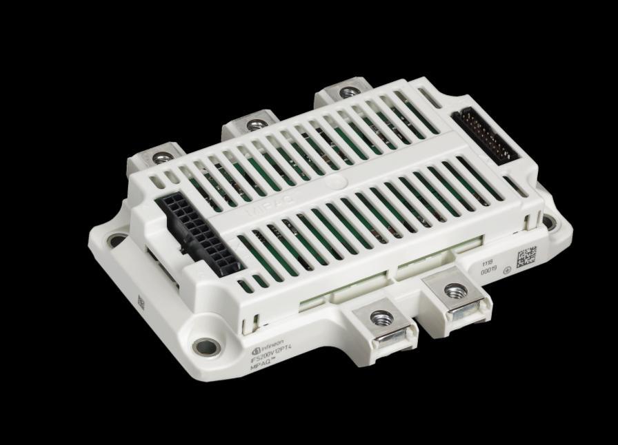
6 2 Mechanical Features Figure 1 shows the MIPAQ serve with its most obvious mechanical features: Micro-Fit connector for driver supply: X1 AC-Power Terminals for metric 6mm screws Milli-Grid connector for 5Vsupply and logic signals: X2 Mounting holes for 5mm screws DC-Power Terminals for metric 6mm screws Figure 1 MIPAQ serve in the established EconoPACK 4 housing 3 Schematic Overview In Figure 2 an overview of the electric components within the MIPAQ serve is depicted: Figure 2 Overview on the electric components within the MIPAQ serve The included driver is based on Infineon s Coreless Transformer Technology and provides all features known from the single IGBT-Driver 1ED020I12-F. For a detailed description of the driver-ic please refer to the according Datasheet. 6
7 4 Adapted Driver Electronics The electronics included in the MIPAQ serve is optimized to properly drive and protect the IGBTs. The following sections describe the special features provided by the driver. 4.1 Necessary Power Supply To properly supply the drivers with power it is necessary to have four voltage sources that are galvanically separated. The isolation between these voltages has to be sufficient for 1200V-applications. Switch mode power supplies like the one shown in Figure 3 can be used to provide bipolar voltages of +16V/GND/-8V as recommended in the MIPAQ datasheet as typical values. Figure 3 Example for a switch mode power supply Slight differences especially in the transformer and tolerances among the used components will lead to variations of the output voltages as the depicted design only provides a non regulated supply. Care should be taken to minimize these deviations of the output voltages if several supplies are designed in this manner. The power consumption of the drivers varies with temperature and switching frequency. To properly operate the module under all specified conditions the supply has to be designed for the worst case, represented by 20kHz switching frequency at 85 C base plate temperature. Under these conditions, the supplies for the high-side drivers have to be capable to provide a maximum output current of 40mA. At the low-side the supply has to provide three drivers and the temperature measurement with power; consequently, it has to be capable to drive a maximum current of 120mA. 7

8 4.1.1 Driver Supply Connector In Figure 1 the mechanical features of the MIPAQ serve are mentioned, showing the pluggable connector for the IGBT-driver power supply. To ensure availability all over the world, a 2-row 22-pin header of the Molex Micro-Fit series was chosen for the MIPAQ serve with a pin assignment as presented in Figure 4. Figure 4 Pin assignment of the driver supply connector X1 To achieve the clearance distances mandatory for 1200V-modules, one row of pins between two supply voltages is intentionally left blank thus increasing the distance between active pins. The header used mates to Molex receptacle-type Crimp terminals of Molex-type have to be used to tailor the connecting wires to match individual needs. A symbolic representation of the receptacle and terminal are depicted in Figure 5. Figure 5 Molex receptacle and appropriate terminal The crimping can be done manually if desired. An according crimping tool is available from Molex, order number Logic Signal Connections Depending on the isolation needs, there are two possibilities to connect the MIPAQ serve to a given control electronics. As basic isolation is already included a direct connection between control and power electronics is possible if this level of isolation is sufficient. To achieve reinforced isolation, a second basic isolation barrier in series to the one implemented within the module is needed. This barrier can be built using any means of isolation available. A traditional approach can be made by utilizing optoelectronic couplers. 8
9 Figure 6 depicts an example using magnetic couplers to add basic isolation to the gate signal paths. In principle, this solution can also be used for the error signals provided by the drivers. Figure 6 Additional basic isolation for gate-signals Logic Signal Connector Connecting the signals and the necessary 5V-supply to the module is done using a Molex Milli-Grid connector in 22-pin 2-row header configuration with a pin assignment as visible in Figure 7. Figure 7 Pin assignment for X2: 5V-supply and logic signals All necessary pull-up resistors are included in the MIPAQ serve, no further external elements need to be added. B1 to B3 refers to the bottom-side transistors, T1 to T3 to the top-side. Reset /RST and fault-signals /FLT_B, /FLT_T are low-active. The logic supply s +5V are referenced to the according control electronic. Positive logic is utilized for the gate signals. The control signals for the gate driver are 5V-cmos compatible and considered low at voltages up to 1.5V and high at levels 3.5V and above. The 5V-supply has to be provided within a tolerance of 0.5V, the module takes a maximum current of 50mA out of the 5V-source. 9


10 The header integrated into the MIPAQ serve mates to a receptacle type for ribbon wire. Optionally a strain relief with order number is available. Both parts are shown in Figure 8. Figure 8 Milli-Grid receptacle and strain relief Due to the different geometries the two connectors can not be swapped. Additionally both connectors are locked to protect them from vibration. Furthermore, the receptacles feature keys making it impossible to mount them in the wrong direction. 5 Connecting wires The connections to power- and logic side have to be tailor made regarding the applicational needs. Due to the wired connection, the MIPAQ serve eases the design of the interconnection between control electronics and power section. Though it is recommended to keep the connecting wires as short as possible a maximum length not exceeding 3 meters is possible. It has to be ensured that the connections to powerand logic side are clearly separated from the high current paths to avoid cross-conduction and malfunctions of the electronics. The power connection is based on single wires with crimped terminals. A conductor area of 0.5mm² is recommended. To achieve proper levels of isolation further isolation layers e.g. tubes can be used. To connect the logic signals, a ribbon cable with 22 conductors is necessary. As the connector features 2mm pin-to-pin spacing, the cable has to provide a 1mm pitch. Examples for tailor-made wires are given in Figure 9: Figure 9 Wires for power and logic connection 10
11 6 Implemented Protection Features The MIPAQ serve is equipped with the 1ED020I12-F driver-ic. The relevant protection features implemented within this driver concern undervoltage lockout and short circuit detection. Undervoltage lockout refers to the supply voltages of the driver. Below the threshold voltage the driver provides an error signal and keeps the according IGBT turned off. These error-signals are logically or-connected to provide a dedicated READY in two groups separately showing the condition of the three top-side drivers as one group and the low-side drivers as the second group. The driver s outputs only become active if all drivers are properly supplied. The short circuit protection is based on desaturation voltage detection. If a short circuit appears, the collector-emitter-voltage of the IGBT rises rapidly. At a level of about 9V the DESAT-detection of the gate driver is activated turning off the related IGBT. To prevent accidental turn-off a blanking time of approximately 6µs is implemented. This blanking time is necessary to prevent the desaturation detection from being triggered if capacitive loads such as long wires need to be handled. The specified short circuit withstand time of IGBT4 is 10µs and the IGBT is turned of well within this limit if short circuit is detected. A typical short circuit turn-off is shown in Figure 10. Figure 10 Typical short circuit turn-off, U DC =750V, I max ~800A, t sc ~7µs green trace: Collector 200A/div blue trace: Collector-Emitter 200V/div red trace: Gate-Emitter 10V/div The short circuit protection is specified to properly work with up to 850V DC-Link voltage as long as the overall DC-Link stray inductance is kept below 100nH including the module. 11
12 7 Digital Temperature Measurement Based on the internal NTC a temperature measurement is set up. The digital information about the baseplate temperature is coded in the output frequency. Counting pulses of the temperature signal for a determined time includes the information on the temperature; the relation is hinted out in Figure 11: Temperature [ C] Deviation [K] Pulses in 100ms Measurement Deviation 5th OrderApproximation Figure 11 Relation between temperature and pulses counted Pulses were counted for 100ms. The graph also includes a 5 th order approximation to the measurement done; the temperature T can be calculated from x pulses in 100ms to be: T [ C] = 2,2130E-12x 5-5,6476E-09x 4 + 5,5375E-06x 3-2,5924E-03x 2 + 6,9881E-01x - 38,703 The added purple line shows the absolute difference between this approximation and the true temperature that was measured as well. This approach achieves an absolute accuracy within 1K for the temperature range of interest. Of course several other fittings or multiple polygonal linearizations can be done. As the NTC used for the measurement has a tolerance on its own, it is recommended to calibrate the measurement at a well defined temperature to achieve the most reliable and accurate reading. As for the all logic signals, the temperature signal as well is galvanically isolated from the power electronic section using Infineon s Coreless Transformer Technology to form a basic isolation barrier. The electronics used to read out the NTC along with the isolation barrier involved has to be properly supplied to operate. Internally, the supply is taken from the low-side driver supply connected to X1.19 and X1.21. To test the temperature measurement, at least the 5V logic supply at X2.12 along with the low-side supply at X1.19/21 has to be available to generate the temperature signal NTC+ at X
13 8 Handling and Mounting MIPAQ does not refer to a certain package but to functionality. Mounting and handling different modules however is related to the package utilized. The following sections interlink the Application Notes on how to mount and handle different packages. For any given module it is recommended to apply thermal grease to form a proper thermal interface to the heatsink. As described in the Application Note AN Application of screen print templates to paste thermal grease within IGBT modules it is recommended to utilize a process that achieves sufficiently reproducible results. The document can be downloaded at Infineon's Document Database 8.1 MIPAQ serve in EconoPACK 4-Packages For mounting and handling instructions regarding EconoPACK 4-Type modules please refer to the application note AN EconoPACK 4 Product Family - Mounting instructions / Application Note, please use the link above to go to Infineon s Document Database. 13
Application Note No. 097
 Application Note, Rev. 1.0, Mai. 2006 Application Note No. 097 Using BCR402R/BCR402U at High Supply Voltages RF & Protection Devices Edition 2006-05-08 Published by Infineon Technologies AG 81726 München,
NovalithIC H-Bridge Demo Board
 Demo Board Description V1.0, 2011-09-23 Automotive Power General Description Figure 1 Demo board (top view) 1 General Description The NovalithIC H-Bridge/Dual-Halfbridge Demo Board contains two NovalithICs
Application Note, V 1.1, Feb AP DAP Connector. Microcontrollers
 Application Note, V 1.1, Feb. 2009 AP24003 Microcontrollers Edition 2009-02 Published by Infineon Technologies AG 81726 München, Germany Infineon Technologies AG 2009. All Rights Reserved. LEGAL DISCLAIMER
Industrial PROFET. Universal Application Board User s Manual
 Industrial PROFET Universal Application Board User s Manual Introduction Industrial PROFET Universal Application Board The Industrial PROFET demo board can be used to easily evaluate a wide range of single
Application Note, V1.0, Jul AP08049 XC886/888CLM. Migration of Flash to ROM Device: Memory Protection Configurations.
 Application Note, V1.0, Jul. 2006 AP08049 XC886/888CLM Migration of Flash to ROM Device: Memory Protection Configurations Microcontrollers Edition 2006-07 Published by Infineon Technologies AG 81726 München,
Application Note, V 1.1, Apr AP08006 C868. Interfacing SPI/I2C Serial EEPROM with C868 Microcontroller. Microcontrollers. Never stop thinking.
 Application Note, V 1.1, Apr. 2005 AP08006 C868 Interfacing SPI/I2C Serial EEPROM with C868 Microcontroller Microcontrollers Never stop thinking. Edition 2005-04-01 Published by Infineon Technologies AG
Application Note, V1.0, Aug AP08064 XC866/886/888. Safeguarding the Microcontroller under Out-of-Spec Noise Conditions.
 Application Note, V1.0, Aug. 2007 XC866/886/888 AP08064 Safeguarding the Microcontroller under Out-of-Spec Noise Conditions Microcontrollers Edition 2007-08 Published by Infineon Technologies AG 81726
Smart High-Side Power Switch BSP742RI PG-DSO8. AEC qualified Green product (RoHS compliant)
") AEC qualified Green product (RoHS compliant) Ω PG-DSO8 General Description N channel vertical power FET with charge pump, ground referenced CMOS compatible input and diagnostic feedback, monolithically
AEC qualified Green product (RoHS compliant) Ω PG-DSO8 General Description N channel vertical power FET with charge pump, ground referenced CMOS compatible input and diagnostic feedback, monolithically
Power Management & Drives. Application Note. February AN-EVAL 2x8-ISO1H815G-1
 February 2010 Application Note AN-EVAL 2x8-ISO1H815G-1 Coreless Transformer Isolated High Side Switch Evaluation Board 2 x 8 Channel 1.2A with ISO1H815G Published by Infineon Technologies AG http://www.infineon.com
XE166 Family AP Application Note. Microcontrollers. X E D r i v e C a r d H a r d w a r e D e s c r i p t i o n Board REV.
 XE166 Family AP16160 X E 1 6 4 D r i v e C a r d H a r d w a r e D e s c r i p t i o n Application Note V1.0, 2009-03 Microcontrollers Edition 2009-03 Published by Infineon Technologies AG 81726 Munich,
XC2000 Family AP Application Note. Microcontrollers. XC2236N Drive Card Description V1.0,
 XC2000 Family AP16179 Application Note V1.0, 2010-07 Microcontrollers Edition 2010-07 Published by Infineon Technologies AG 81726 Munich, Germany 2010 Infineon Technologies AG All Rights Reserved. LEGAL
AP XC2000 & XE166 Families. Design Guidelines for XC2000 & XE166 Microcontroller Board Layout. Microcontrollers
 Application Note, V2.1, Jun. 2008 AP16116 XC2000 & XE166 Families Design Guidelines for XC2000 & XE166 Microcontroller Board Layout Microcontrollers Edition 2008-06-24 Published by Infineon Technologies
Operating temperature T a
 Ω Operating temperature T a -24 Green Product (RoHS Compliant) General Description N channel vertical power FET with charge pump, ground referenced CMOS compatible input, monolithically integrated in Smart
Smart High-Side Power Switch for Industrial Applications One channel: 1 x 1 Ω
 Smart High-Side Power Switch for Industrial Applications One channel: 1 x 1 Ω ITS 4140N Features Current controlled input Product Summary Overvoltage protection V bbin(az) 62 V Operating voltage V Short
TLS202B1. Demonstration Board Manual. Automotive Power. Demonstration Board Manual. Rev. 1.0,
 Rev. 1.0, 2013-06-12 Automotive Power Introduction 1 Introduction The TLS202B1 application board is a demonstration of the Infineon low drop out linear voltage post regulator. The TLS202B1 is the ideal
AN MA040E12_EVAL Isolated Gate Driver Power Supply and Logic Interface for MIPAQ TM Serve
 AN2010-04 MA040E12_EVAL Isolated Gate Driver Power Supply IFAG IMM INP M AE Edition 2010-05-07 Published by Infineon Technologies AG 59568 Warstein, Germany Infineon Technologies AG 2010. All Rights Reserved.
Easy Kit Board Manual
 User s Manual, V1.0, June2008 Easy Kit Board Manual Easy Kit - XC88x Microcontrollers Edition 2008-06 Published by Infineon Technologies AG, 81726 München, Germany Infineon Technologies AG 2008. All Rights
PROFET TM + Demoboard. Automotive Power. Smart High-Side Power Switch - Demoboard Description. Rev. 1.4,
 PROFET TM + Smart High-Side Power Switch - Demoboard Description Demoboard Rev. 1.4, 2011-02-16 Automotive Power Table of Contents Table of Contents 1 Overview.......................................................................
SPI Protocol of the TLE941xy family
 Protocol of the TLE941xy family Application Note Rev 1.0, 2016-04-25 Automotive Power Table of Contents 1 Abstract........................................................................ 3 2 Introduction.....................................................................
TLT807B0EPV Demoboard
 Preface Scope and purpose This application note provides information about the usage of the TLT807B0 Demoboard. The TLT807B0 Demoboard is used to demonstrate the ultra low quiescent current linear voltage
Relaisdriving with HITFETs and SPIDERs
 Relaisdriving with HITFETs and SPIDERs Driving automotive relais with protected low side drivers Application Note HITFET AP01-2009 Rev. 1.1 April 2011 Automotive Power HITFETS Table of Contents Table of
Application Note, V1.3, September 2008 AP XC2000/XE166 Family. Microcontrollers
 Application Note, V1.3, September 2008 AP16103 XC2000/XE166 Family P i n C o n f i g u r a t i o n, P o w e r S u p p l y a n d R e s e t Microcontrollers Edition 2008-09-18 Published by Infineon Technologies
Design Guideline for TC1782 Microcontroller Board Layout
 TC1782 AP32145 Application Note V1.4 2012-02 Microcontrollers Edition 2012-02 Published by Infineon Technologies AG 81726 Munich, Germany 2012 Infineon Technologies AG All Rights Reserved. LEGAL DISCLAIMER
Application Note No. 100
 Application Note, Rev. 1.2, May 2007 Application Note No. 100 ESD Protection for High-Speed Applications 1- & 2-channel low capacitance bi-directional ESD diode in ultra-small TSLP package Small Signal
Chip Card & Security ICs SLE Intelligent 256-Byte EEPROM with Write Protection function and Programmable Security Code
 Chip Card & Security ICs SLE 5542 Intelligent 256-Byte EEPROM with Write Protection function and Programmable Security Code Short Product Information May 2006 Short Product Information Revision History:
Application Note, V 1.0, April 2005 AP32086 EMC. Design Guideline for TC1796 Microcontroller Board Layout. Microcontrollers. Never stop thinking.
 Application Note, V 1.0, April 2005 AP32086 EMC Design Guideline for TC1796 Microcontroller Board Layout Microcontrollers Never stop thinking. TriCore Revision History: 2005-04 V 1.0 Previous Version:
Chip Card & Security ICs SLE Intelligent 1024 Byte EEPROM with Write Protection and Programmable Security Code
 Chip Card & Security ICs SLE 5528 Intelligent 1024 Byte EEPROM with Write Protection and Programmable Security Code Short Product Information May 2007 Short Product Information Revision History: Current
Design Guideline for TC1791 Microcontroller Board Layout
 TC1791 AP32162 Application Note V1.2 2012-02 Microcontrollers Edition 2012-02 Published by Infineon Technologies AG 81726 Munich, Germany 2012 Infineon Technologies AG All Rights Reserved. LEGAL DISCLAIMER
XE166 Family AP Application Note. Microcontrollers. UConnect XE162N Hardware Description V1.0,
 XE166 Family AP90005 Application Note V1.0, 2010-01 Microcontrollers Edition 2010-01 Published by Infineon Technologies AG 81726 Munich, Germany 2010 Infineon Technologies AG All Rights Reserved. LEGAL
ESD5V3U4RRS. Type Package Configuration Marking ESD5V3U4RRS SOT363 6 pins, uni-directional E8s
 UltraLow Capacitance ESD Diode Array Railtorail diodes with internal TS diode ESD / transient protection of four lines and one cc line exceeding: IEC00 (ESD): ± 5 k (contact) IEC00 (EFT):.5 k / 50 A (5/50
AgileSwitch Gate Drivers EDEM2-EconoDual TM Electrical Series User Manual
 AgileSwitch Gate Drivers EDEM2-EconoDual TM Electrical Series User Manual EDEM2-EconoDual Electrical Manual V01 PRELIMINARY Page 1 of 20 Contents Abstract... 3 Software Programmable Features... 3 Key Switch
LOW EMI PWM INTELLIGENT POWER HIGH SIDE SWITCH
 Automotive grade Automotive IPS High side AUIPS72211R LOW EMI PWM INTELLIGENT POWER HIGH SIDE SWITCH Features Integrated bootstrap for 100kHz switching Optimized EMI switching Charge pump for DC operation
Absolute Pressure Sensor
 November 2007 Absolute Pressure Sensor Data Sheet Rev 2.14 Sense & Control Edition 2007-11-23 Published by Infineon Technologies AG 81726 München, Germany 2007 Infineon Technologies AG All Rights Reserved.
Design Guideline for TC1798 Microcontroller Board Layout
 TC1798 AP32164 Application Note V1.2 2012-02 Microcontrollers Edition 2012-02 Published by Infineon Technologies AG 81726 Munich, Germany 2012 Infineon Technologies AG All Rights Reserved. LEGAL DISCLAIMER
Data Sheet 1SD536F2-MG1200FXF1US53 Single-Channel SCALE Plug-and-Play IGBT Driver
 Data Sheet 1SD536F2-MG1200FXF1US53 Single-Channel SCALE Plug-and-Play IGBT Driver Ultra-compact, high-performance driver for 2-level, 3-level and multilevel converters Abstract The SCALE plug-and-play
TxD GND V CC. RxD WAKE V IO SCLK MISO. (Top-side x-ray view) SCLK INH
 SCLK INH") Application Note PB Layout Recommendations for TLE9255W About this document Scope and purpose This document provides application information for the transceiver TLE9255W from Infineon Technologies AG as
Application Note PB Layout Recommendations for TLE9255W About this document Scope and purpose This document provides application information for the transceiver TLE9255W from Infineon Technologies AG as
User Guide for MA Evaluation Boards MA12040/MA12040P/MA12070/MA12070P
 User Guide for MA Evaluation Boards MA12040/MA12040P/MA12070/MA12070P About this document Scope and purpose The Evaluation Board is an evaluation and demonstration board for MA12040, MA12040P, MA12070,
DSP-BASED MOTOR CONTROLLER FOR THREE-PHASE BRUSHLESS DC MOTORS
 DSP-BASED MOTOR CONTROLLER FOR THREE-PHASE BRUSHLESS DC MOTORS FEATURES / BENEFITS Embedded Motor Control DSP (ADMCF328) improves higher level system integration and flexibility 7A phase current (cycle-by-cycle
2BB0535T2Ax-17 Target Data Sheet
 2BB0535T2Ax-17 Base Board for 2SC0535T SCALE-2 drivers for 1700V IGBT modules with a combined electrical/fiber-optic interface for 2-level, 3-level and multilevel converter topologies with paralleling
Data Sheet 1SD210F2-5SNA1200G Single-Channel SCALE Plug-and-Play IGBT Driver
 Data Sheet 1SD210F2-5SNA1200G450300 Single-Channel SCALE Plug-and-Play IGBT Driver Ultra compact, high-performance driver for 2-level, 3-level and multilevel converters Abstract The SCALE plug-and-play
3D Magnetic Sensor 2 Go - TLE493D-A2B6
 TLE493D-A2B6 3D-MS2GO User Manual About this document Scope and purpose This document provides an introduction to the 3D Magnetic Sensor 2 Go kit and should enable the reader to efficiently carry out own
ESD8V0L... ESD8V0L1B-02LRH. Type Package Configuration Marking ESD8V0L1B-02EL
 Low Capacitance TVS Diode ESD / transient protection of highspeed data lines in. / 5 / V applications according to: IEC6000 (ESD): up to ± 5 KV (contact) IEC6000 (EFT): 0 A (5/50 ns) IEC60005 (surge):
Documentation Addendum, V1.2, Aug TC Bit Single-Chip Microcontroller Delta BC-to-BE Step. Microcontrollers
 Documentation Addendum, V1.2, Aug. 2007 TC1796 32-Bit Single-Chip Microcontroller Microcontrollers Edition 2007-08 Published by Infineon Technologies AG 81726 Munich, Germany 2007 Infineon Technologies
RF Power Product Selection Guide LDMOS Transistors and ICs
 RF Power Product Selection Guide LDMOS Transistors and ICs www.infineon.com/rfpower RF Power Product Selection Guide INFINEON S state-of-the-art LDMOS technology, high-volume manufacturing facilities and
Scope: SW Installation: Start the Package PROG-KIT. Current. Page 1
 Sensor 2 Go Quick Instruction Guide Scope: The following instruction gives a quick overview about the Sensor r 2 Go GUI. The GUI can also be used for the PGSISI-2 based TLI4970050 PROG-KIT. SW Installation:
XE164 UConnect Manual, V.1.1, February XE164 UConnect. Board REV. 2007/40. Microcontrollers. Never stop thinking.
 Manual, V.1.1, February 2008 XE164 Board REV. 2007/40 Microcontrollers Never stop thinking. Edition 2007-06 Published by Infineon Technologies AG 81726 München, Germany Infineon Technologies AG 2008. All
2.5 A Output Current, IGBT Drive Optocoupler with Desaturation Detection and Isolated Fault Sensing. Featured Fairchild Product/s: FOD8316
 User Guide for FEBFOD8316 Evaluation Board 2.5 A Output Current, IGBT Drive Optocoupler with Desaturation Detection and Isolated Fault Sensing Featured Fairchild Product/s: FOD8316 Direct questions or
Data Sheet 1SD210F2-5SNA0750G Single-Channel SCALE Plug-and-Play IGBT Driver
 Data Sheet 1SD210F2-5SNA0750G650300 Single-Channel SCALE Plug-and-Play IGBT Driver Ultra compact, high-performance driver for 2-level, 3-level and multilevel converters Abstract The SCALE plug-and-play
2BB0108T2Ax-12 Target Data Sheet
 2BB0108T2Ax-12 Basic board for 2SC0108T SCALE-2 driver for 1200V IGBT modules or MOSFETs with an electrical interface for 2-level, 3-level and multilevel converter topologies with paralleling capability
Application Note - PCB Layout & PIN Behavior Assessment
 Application Note - PB Layout & PIN Behavior Assessment Scope and purpose This document provides application information for the transceiver TLE9252V from Infineon Technologies AG as Physical Medium Attachment
2BB0435T2Ax-12 Target Data Sheet
 2BB0435T2Ax-12 Base Board for 2SC0435T SCALE-2 driver for 1200V IGBT modules or MOSFETs with an electrical interface for 2-level, 3-level and multilevel converter topologies with paralleling capability
STEVAL-IPMnM2N. Motor control power board based on the SLLIMM-nano 2 nd series. Description. Features. RoHS compliant
 Motor control power board based on the SLLIMM-nano 2 nd series Data brief RoHS compliant Features Input voltage: from 125 to 400 VDC Nominal power: up to 100 W Nominal current: up to 1.2 A rms Input auxiliary
Reference Design. ACPL-333J Fuji Electric AT-NPC 3-Level 12in1 IGBT Module. 1. Introduction. 2-Level Inverter. A-NPC 3-Level Inverter
 ACPL-333J Fuji Electric AT-NPC 3-Level 12in1 IGBT Module Reference Design 1. Introduction In 2010, Fuji Electric launched a platform featuring 3-level Converter circuit. With the success, Fuji Electric
Dual H-Bridge shield. Dual H-Bridge shield - board user manual. Shield for DC motor control with IFX9202. About this document.
 - board user manual Dual H-Bridge shield About this document Scope and purpose This document details the functionality and the required steps for running the Dual H-Bridge shield. Included are instructions
6SP0235T2Ax-FS800R07A2E3 Target Data Sheet
 6SP0235T2Ax-FS800R07A2E3 Compact, high-performance, plug-and-play six-channel IGBT driver based on SCALE-2 technology for automotive modules HybridPACK TM 2 Abstract The SCALE-2 plug-and-play driver 6SP0235T2Ax-FS800R07A2E3
XMC LED current control explorer kit
 XMC LED current control explorer kit Quick start guide The XMC LED current control explorer kit is an evaluation kit that introduces the user to continuous conduction mode buck LED driving solution with
Application Note, V1.0, November AP XC2000/XE166 family. ADC Result Handling on XC2000/XE166 family of Microcontrollers.
 Application Note, V1.0, November. 2008 AP16155 XC2000/XE166 family ADC Result Handling on XC2000/XE166 family of Microcontrollers Microcontrollers Edition 2008-11-11 Published by Infineon Technologies
Data Sheet EB01-FS450R17KE3 Basic Board for Infineon EconoPACK+ Modules FS450R17KE3
 Data Sheet EB01-FS450R17KE3 Basic Board for Infineon EconoPACK+ Modules FS450R17KE3 Abstract The EB01-FS450R17KE3 is a basic board to be used with six-channel driver 6SD312EI for reliable driving and safe
2SP0320T Preliminary Description & Application Manual
 2SP0320T Preliminary Description & Application Manual Driver solution for IGBT modules from Danfoss, Fuji and Infineon with an electrical interface for 2-level, 3-level and multilevel converter topologies
BG2E Universal Gate Drive Prototype Board
 Application NOTES: First Release: March 23, 200 BG2E Universal Gate Drive Prototype Board Description: BG2E is a fully isolated two channel gate drive circuit designed for use with dual NX-L series IGBT
AP16050 SAB C161V/K/O. Emulating an asynchronous serial interface (ASC) via software routines. Microcontrollers. Application Note, V 1.0, Feb.
 via software routines. Microcontrollers. Application Note, V 1.0, Feb.") Application Note, V 1.0, Feb. 2004 SAB C161V/K/O Emulating an asynchronous serial interface (ASC) via software routines. AP16050 Microcontrollers Never stop thinking. TriCore Revision History: 2004-02
Application Note, V 1.0, Feb. 2004 SAB C161V/K/O Emulating an asynchronous serial interface (ASC) via software routines. AP16050 Microcontrollers Never stop thinking. TriCore Revision History: 2004-02
XMC1000 EEPROM emulation and data retention
 AP32384 EEPROM emulation and data retention About this document Scope and purpose This document provides a brief introduction to the use of the Microcontroller family with emulated EEPROM. Intended audience
2. Control Pin Functions and Applications
 IMARY CONTROL ( PIN) Module Enable / Disable. The module can be disabled by pulling the below 2.3 V with respect to the Input. This should be done with an open-collector transistor, relay, or optocoupler.
Do s and Don ts with SCALE -2 Gate Drivers
 Do s and Don ts with SCALE -2 Gate Drivers SCALE -2 IGBT Driver Cores and Plug-and-Play Drivers Introduction and Overview This highlights important points that must be considered when using SCALE -2 driver
Sensor supply in bus mode
 Sensor supply in bus mode Product Family: TLE5011, TLE5012, TLE5012B, TLE5012BD, TLI5012B About this document Scope and purpose Some applications require the use of several devices connected to the same
Bootstrap Circuitry Selection for Half-Bridge Configurations
 Application Report Bootstrap Circuitry Selection for Half-Bridge Configurations Mamadou Diallo, High Power Drivers ABSTRACT Driving MOSFETs in half-bridge configurations present many challenges for designers.
EV-VND7040AJ. VND7040AJ evaluation board. Features. Applications
 VND7040AJ evaluation board Data brief Features Max transient supply voltage V CC 40 V Operating voltage range V CC 4 to 28 V Typ. on-state resistance (per Ch) R ON 40 mω Current limitation (typ) I LIMH
Advanced Features in Sophisticated Inverter Design Supporting MW-Applications
 www.pcim-europe.com Advanced Features in Sophisticated Inverter Design Supporting MW-Applications Dr. Peter Lahl, Infineon Technologies AG, Germany, peter.lahl@infineon.com Stefan Schmies, Infineon Technologies
Operating instructions. Standstill monitor A / / 2011
 Operating instructions Standstill monitor A300 UK 1 2 3 4 5 6 7 8 7390337 / 01 02 / 2011 1 2 3 4 5 6 7 8 switchpoint min max pulse/min power Made in Germany ifm electronic gmbh D 45127 Essen func. I II
ACS Stepper Controller. Econo Stepper Controller
 ACS Stepper Controller & Econo Stepper Controller User's Manual June 22, 2005 6 2 3 3 E. S a w g ra s s R d S a ra s o ta, F L. 3 4 2 4 0 (9 4 1 )3 7 7-5 7 7 5 F A X(9 4 1 )3 7 8-4 2 2 6 www.acscontrol.com
Data Sheet IHD 260/660 Dual Channel SCALE IGBT Driver Core
 Data Sheet IHD 260/660 Dual Channel SCALE IGBT Driver Core A successor to the IHD 215/280/680 dual-gate driver cores for 1200V and 1700V IGBTs The IHD 260 and IHD 660 (short IHDx60) are highly-integrated
HARDWARE MANUAL TMCM-1613 TMCM-1613-REC. Hardware Version V TRINAMIC Motion Control GmbH & Co. KG Hamburg, Germany.
 MODULES FOR BLDC MOTORS MODULES Hardware Version V 1.10 HARDWARE MANUAL + + TMCM-1613 + + Single Axis BLDC Controller / Driver Block-commutation Hall-sensor based Analog+digital inputs / outputs Up-to
1SP0635x2xx-FZ3600R17HP4 Preliminary Data Sheet
 Compact, high-performance, plug-and-play single-channel IGBT driver based on SCALE-2 technology for individual and parallel-connected modules in 2-level, 3-level and multilevel converter topologies Abstract
1SP0635V / 1SP0635S / 1SP0635D Preliminary Description & Application Manual
 1SP0635V / 1SP0635S / 1SP0635D Preliminary Description & Application Manual Driver solution for high-voltage and high-power IGBT modules with fiber-optic interface for 2-level, 3-level and multilevel converter
TLx5012B 2go Evaluation Kit
 About this document Scope and purpose This document describes the evaluation kit for the TLx5012B GMR based angle sensor. The purpose of this document is to describe the software installation process and
SCALE Dual-Channel Plug-and-Play Driver. Driver solution for 130mm x 140mm dual IGBT modules with electrical interface for 2-level topologies
 Data Sheet -CM800DZ-34H SCALE Dual-Channel Plug-and-Play Driver Driver solution for 130mm x 140mm dual IGBT modules with electrical interface for 2-level topologies Abstract The -CM800DZ-34H is a dual-channel
Application Note No. 104
 Application Note, Rev. 1.0, August 2007 Application Note No. 104 2-channel bi/uni-directional TVS diodes for ESD protection in /LIN bus applications ESD24VS2B, ESD24VS2U Small Signal Discretes Edition
Security & Chip Card ICs SLE 55R04. Intelligent 770 Byte EEPROM with Contactless Interface complying to ISO/IEC Type A and Security Logic
 Security & Chip Card ICs SLE 55R04 Intelligent 770 Byte EEPROM with Contactless Interface complying to ISO/IEC 14443 Type A and Security Logic Short Product Information January 2001 Short Product Information
CUS150M1 Instruction Manual
 BEFORE USING THE POWER SUPPLY UNIT Be sure to read this instruction manual thoroughly before using this product. Pay attention to all cautions and warnings before using this product. Incorrect usage could
Application Note, V1.0, Jul AP XC16x. Interfacing the XC16x Microcontroller to a Serial SPI EEPROM. Microcontrollers
 Application Note, V1.0, Jul. 2006 AP16095 XC16x Interfacing the XC16x Microcontroller to a Serial SPI EEPROM Microcontrollers Edition 2006-07-10 Published by Infineon Technologies AG 81726 München, Germany
BG1B Universal Gate Drive Prototype Board
 BG1B Universal Gate Drive Prototype Board Description: The BG1B is a single channel gate drive circuit board for high power IGBT modules. The BG1B utilizes Powerex hybrid gate drivers and DC-to-DC converters
Technical Explanation TechEx Board SEMIX5MLI SKYPER 12
 Technical Explanation TechEx Board SEMIX5MLI SKYPER 12 Revision: 02 Issue date: 2017-04-20 Prepared by: J.Krapp Approved by: Name Keyword: IGBT Driver 1. Introduction... 1 2. Application hints... 2 3.
CPCI-USB-5. CPCI-USB 2.0 Interface with 6 USB Ports. Hardware Manual. to Product I.2326.xx
 CPCI-USB-5 CPCI-USB 2.0 Interface with 6 USB Ports Hardware Manual to Product I.2326.xx CPCI-USB-5 Hardware Manual Doc. No.: I.2326.21 / Rev. 1.0 Page 1 of 18 esd electronic system design gmbh Vahrenwalder
Type Terminal Block Connector No. of poles Appearance Model 40 XW2B-40G4 50 XW2B-50G4 40 XW2B-40G5 *1 50 XW2B-50G5 60 XW2B-60G5 40 XW2B-40G5-T
 Standard-type Connector- Conversion Units XWB CSM_XWB_DS_E Simplifies Connector and terminal block replacement, and requires less in-panel wiring. Mount to DIN Track or via screws. MIL Flat Cable Connectors
VRM 8.1 DC-DC Converter Design Guidelines
 VRM 8.1 DC-DC Converter Design Guidelines May 1997 Order Number: 243408-001 Information in this document is provided in connection with Intel products. No license, express or implied, by estoppel or otherwise,
2SP0115T2Ax-2MBI300VN Preliminary Data Sheet
 2SP0115T2Ax-2MBI300VN-170-50 Compact, high-performance, plug-and-play dual-channel IGBT driver based on SCALE-2 technology for individual and parallel-connected modules Abstract The SCALE-2 plug-and-play
Application Note TLE9252V. About this document. Application Note. Safety Recommendations Z8F
 Application Note TLE9252V Safety Recommendations About this document Scope and purpose This document provides application information for the transceiver TLE9252V from Infineon Technologies AG as Physical
Agilent 84904, 6, 7K/L Programmable Step Attenuators
 Agilent 84904, 6, 7K/L Programmable Step Attenuators Data Sheet High Accuracy,Excellent Reliability, Long Life Features and description DC to 26.5 GHz, DC to 40 GHz frequency coverage Optional calibration
Brushless DC Motor Controller Specification Assembly 025A0053
 Brushless DC Motor Controller Specification Assembly 025A0053 600A0053 Rev. 2 July 28, 2004 025A0053 Brushless DC Motor Controller Data Sheet Page 1 Revision History Date Rev Description By 5/15/04 1 Initial
Getting Started with the XDPL8220 Reference Board Using.dp Vision Software
 AN_GS_201611_PL21_003 Getting Started with the XDPL8220 Reference Board Using.dp Vision Software XDP T M digital power About this document Scope and purpose The purpose of this document is to give a quick
Description and Application Manual for 2SB315B SCALE Dual-Channel Plug-and-play IGBT Drivers
 for 2SB315B SCALE Dual-Channel Plug-and-play IGBT Drivers Driver solution for 130mm x 140mm dual IGBT modules with fiber-optic interface for 2-level topologies Abstract The 2SB315B is a dual-channel driver
XC82x/XC83x. DMX512 Receiving Device with XC836. Application Note. Microcontrollers AP08131 V1.1,
 XC82x/XC83x DMX512 Receiving Device with XC836 Application Note V1.1, 2012-10 Microcontrollers Edition 2012-10 Published by Infineon Technologies AG 81726 Munich, Germany 2012 Infineon Technologies AG
Assembly and Operating Instructions. M2 module for BDC-i440 control units
 BDC-i440 M2 en Assembly and Operating Instructions M2 module for BDC-i440 control units Important information for: Fitters / Electricians / Users Please forward accordingly! These instructions must be
PRO-1250D CT MID DIN rail three phase four wire energy meter.
 PRO-1250D CT MID DIN rail three phase four wire energy meter. 1.1 Safety instructions 1.2 Foreword 1.3 MID certificate 1.4 Performance criteria 1.5 Specifications 1.6 Basic errors 1.7 Description 1.8 Dimensions
HARDWARE MANUAL TMCM-6110 V TRINAMIC Motion Control GmbH & Co. KG Hamburg, Germany. MODULES FOR STEPPER MOTORS
 MODULES FOR STEPPER MOTORS MODULES V.0 HARDWARE MANUAL + + TMCM-60 6-axes stepper controller / driver up to.a RMS / 24V DC USB, CAN, RS48 + + TRINAMIC Motion Control GmbH & Co. KG Hamburg, Germany www.trinamic.com
2SP0320V and 2SP0320S Description & Application Manual
 2SP0320V and 2SP0320S Description & Application Manual Driver solution for PrimePACK TM IGBT modules with fiber-optic interface for 2-level, 3-level and multilevel converter topologies Abstract 2SP0320V
Linear movement with a 3D sensor
 About this document Scope and purpose After reading this application note you will know how to make the magnetic design for a linear movement application with a Hall based 3D sensor. Directly, magnet and
E2K-F. Flat Capacitive Sensor with a Thickness of Only 10 mm. Flat Proximity Sensor. Ordering Information. Sensors [Refer to Dimensions on page 4.
 Flat Proximity Sensor EK-F CSM_EK-F_DS_E Flat Capacitive Sensor with a Thickness of Only mm Flat Sensor with excellent space efficiency. (Model with built-in Amplifier is only mm thick.) Direct mounting
*X13186* Multimedia and Control Networking Technology. MOST Media Oriented Systems Transport. MediaLB Analyzer Hardware Manual
 Multimedia and Control Networking Technology MediaLB Analyzer MediaLB Monitor USB V1.0.1 3-pin Active-Pod Low Speed V1.0.1 6-pin Active-Pod High Speed V1.0.0 Document Information Version: V2.0.X-2 Date:
5504 Thermocouple Analog Input Module
 550 Thermocouple Analog Input Installation, Operation and Maintenance Setup Manual 5/9/0 Safety Information The information provided in this documentation contains general descriptions and/or technical