SDM-6RO. Expansion Module 6 relay outputs. Manufactured for
|
|
|
- Wilfred Sullivan
- 5 years ago
- Views:
Transcription

1 Version Manufactured for


2 Thank you for choosing our product. This manual will help you with proper support and proper operation of the device. The information contained in this manual have been prepared with utmost care by our professionals and serve as a description of the product without incurring any liability for the purposes of commercial law. This information does not release you from the obligation of own judgement and verification. We reserve the right to change product specifications without notice. Please read the instructions carefully and follow the recommendations contained therein. WARNING! Failure to follow instructions can result in equipment damage or impede the use of the hardware or software. User manual Version z 16
3 1. Safety rules Before first use, refer to this manual Before first use, make sure that all cables are connected properly Please ensure proper working conditions, according to the device specifications (eg: supply voltage, temperature, maximum power consumption) Before making any modifications to wiring connections, turn off the power supply 2. Module Features 2.1. Purpose and description of the module The SDM-6RO module is an innovative device that provides a simple and cost-effective extension of the number of lines of output with high current-carrying capacity. The module has 6 relay outputs. Each relay has three terminals: common (COM), normally open (NO) or normally closed (NC), so that the unit is very flexible. This module is connected to the RS485 bus with twisted-pair wire. Communication is via MODBUS RTU or MODBUS ASCII. The use of 32-bit ARM core processor provides fast processing and quick communication. The baud rate is configurable from 2400 to The module is designed for mounting on a DIN rail in accordance with DIN EN The module is equipped with a set of LEDs used to indicate the status of inputs and outputs useful for diagnostic purposes and helping to find errors. Module configuration is done via USB by using a dedicated computer program. You can also change the parameters using the MODBUS protocol. User manual Version z 16
4 2.2. Technical Specifications Power Supply Relay outputs Temperature Connectors Size Voltage Maximum Current * VDC; 10-28VAC DC: VDC AC: VAC Maximum power consumption DC: 4.8W; AC: 6VA No of outputs 6 The maximum current and voltage (resistive load) Work Storage Power Supply Communication Outputs Configuration Height Length Width 5A 250V AC 10A 24V DC -10 C C -40 C C 2 pins 3 pins 2x 10 pins Mini USB 110 mm 62 mm 88 mm Interface RS485 Up to 128 devices * Maximum current with active Modbus transmission, all outputs on User manual Version z 16
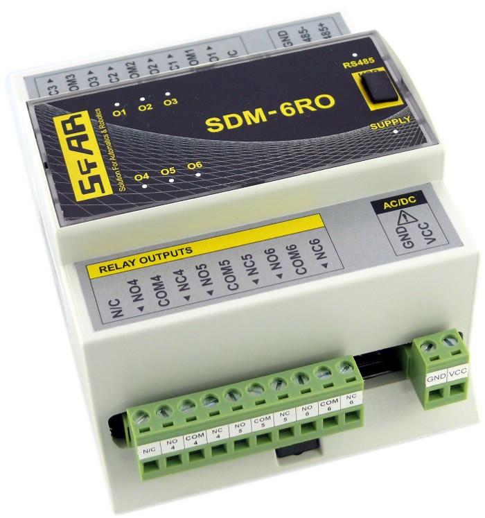
5 2.3. Dimensions of the product Look and dimensions of the module are shown below. The module is mounted directly to the rail in the DIN industry standard. Power connectors, communication and IOs are at the bottom and top of the module. USB connector configuration and indicators located on the front of the module , User manual Version z 16
6 3. Communication configuration 3.1. Grounding and shielding In most cases, IO modules will be installed in an enclosure along with other devices which generate electromagnetic radiation. Examples of these devices are relays and contactors, transformers, motor controllers etc. This electromagnetic radiation can induce electrical noise into both power and signal lines, as well as direct radiation into the module causing negative effects on the system. Appropriate grounding, shielding and other protective steps should be taken at the installation stage to prevent these effects. These protective steps include control cabinet grounding, module grounding, cable shield grounding, protective elements for electromagnetic switching devices, correct wiring as well as consideration of cable types and their cross sections Network Termination Transmission line effects often present a problem on data communication networks. These problems include reflections and signal attenuation. To eliminate the presence of reflections from the end of the cable, the cable must be terminated at both ends with a resistor across the line equal to its characteristic impedance. Both ends must be terminated since the direction of propagation is bidirectional. In the case of an RS485 twisted pair cable this termination is typically 120 Ω Setting Module Address in RS485 Modbus Network The following table shows how to set switch to determine the address of the module. The module address is set with the switches in the range of 0 to 127. Addresses From 128 to 255 can by set via RS485 or USB. Switch Adress SW1 +1 SW2 +2 SW3 +4 SW4 +8 SW5 +16 SW6 +32 SW7 +64 Ex. if switches 1, 3 and 5 are on than module addres is: Address = = 21 User manual Version z 16
7 3.4. Types of Modbus Registers There are 4 types of variables available in the module. Type Beginning adress Variable Access Digital Outputs Digital Inputs Input Registers Output Registers Bit Read & Write Bit Read Registered Read Registered Read & Write Modbus Command 1, 5, , 6, Communication settings You can restore the default configuration by the switch SW8 (see Restore the default configuration) Default settings You can restore the default configuration by the switch SW8 (see Restore the default configuration) Boud rate Pariti Data bits 8 Stop bits 1 Reply Delay [ms] 0 Nie Modbus Type RTU Restore the default configuration To restore the default configuration: turn off the power turn on the switch SW8 turn on the power when power and communication LED start blinking alternately than turn off the switch SW8 Caution! After restoring the default configuration all values stored in the registers will be cleared as well. User manual Version z 16
8 Configuration registers Modbus Dec Hex Name Values x02 Baud rate x04 Parity x03 Stop Bits LSB x03 Data Bits MSB other value * 10 0 none 1 odd 2 even 3 always 1 4 always 0 1 one stop bit 2 two stop bit 7 7 data bits 8 8 data bits x05 Response delay Time in ms x06 Modbus Mode 0 RTU 1 ASCII User manual Version z 16
9 4. Switches ON Switch Function Description 1 Module address +1 2 Module address +2 3 Module address +4 4 Module address +8 5 Module address Module address Module address Restoring default settings Setting module address from 0 to 127 Restoring default settings (see Default settings i Restore the default configuration). User manual Version z 16
 as in the picture below. User manual Version 1.0-5.02.")
10 5. Front panel removing To remove the panel and gain access to the switch, you must pry open the panel using a thin tool (eg a small screwdriver) as in the picture below. User manual Version z 16
11 6. Indicators Outputs 1 3 state Communication ON mini USB configuration connector Outputs 4 6 state Power supply Indicators Power supply Communication Outputs state Description LED indicates that the module is correctly powered. The LED lights up when the unit received the correct packet and sends the answer. LED indicates that the output is on. User manual Version z 16
12 7. Module Connection SHIELD SUPPLY POWER SUPPLY User manual Version z 16
13 8. Modules Registers 8.1. Registered access Modbus Dec Hex Register Name Access Description x00 Version/Type Read Version and Type of the device x01 Switches Read Switches state x02 Baud rate Read & Write RS485 baud rate x03 Stop Bits & Data Bits Read & Write No of Stop bits & Data Bits x04 Parity Read & Write Parity bit x05 Response Delay Read & Write Response delay in ms x06 Modbus Mode Read & Write Modbus Mode (ASCII or RTU) x08 Watchdog Read & Write Watchdog x0C Default Output State Read & Write x20 Received packets LSB Read & Write x21 Received packets MSB Read & Write Default output state (after power on or watchdog reset) No of received packets x22 Incorrect packets LSB Read & Write No of received packets with x23 Incorrect packets MSB Read & Write error x24 Sent packets LSB Read & Write x25 Sent packets MSB Read & Write No of sent packets x33 Outputs Read & Write Output state User manual Version z 16
14 8.2. Bit access Modbus Address Dec Address Hex Address Register name Access Description x0C0 Default state of output 1 Read & Write Default state of output x0C1 Default state of output 2 Read & Write Default state of output x0C2 Default state of output 3 Read & Write Default state of output x0C3 Default state of output 4 Read & Write Default state of output x0C4 Default state of output 5 Read & Write Default state of output x0C5 Default state of output 6 Read & Write Default state of output x330 Output 1 Read & Write Output 1 state x331 Output 2 Read & Write Output 2 state x332 Output 3 Read & Write Output 3 state x333 Output 4 Read & Write Output 4 state x334 Output 5 Read & Write Output 5 state x335 Output 6 Read & Write Output 6 state User manual Version z 16

15 9. Configuration software Modbus Configurator is software that is designed to set the module registers responsible for communication over Modbus network as well as to read and write the current value of other registers of the module. This program can be a convenient way to test the system as well as to observe real-time changes in the registers. Communication with the module is done via the USB cable. The module does not require any drivers. USB PC Communication with the module is done via the USB cable. The module does not require any drivers. Configurator is a universal program, whereby it is possible to configure all available modules. User manual Version z 16


16 Table of content 1. Safety rules Module Features Purpose and description of the module Technical Specifications Dimensions of the product Communication configuration Grounding and shielding Network Termination Setting Module Address in RS485 Modbus Network Types of Modbus Registers Communication settings Default settings Restore the default configuration Configuration registers Switches Front panel removing Indicators Module Connection Modules Registers Registered access Bit access Configuration software...15 Manufactured for: Aspar s.c. ul. Kapitańska Gdynia POLAND ampero@ampero.eu tel ; User manual Version z 16
RS485 MODBUS Module 6RO
 Version 2.0 12/02/2013 Manufactured for Thank you for choosing our product. This manual will help you with proper support and proper operation of the device. The information contained in this manual have
SDM-8AO. Expansion Module 8 analog outputs. Manufactured for
 Version 1.0 16.05.2014 Manufactured for Thank you for choosing our product. This manual will help you with proper support and proper operation of the device. The information contained in this manual have
RS485 MODBUS Module 8AO
 Version 1.3 12/02/2013 Manufactured for Thank you for choosing our product. This manual will help you with proper support and proper operation of the device. The information contained in this manual have
SDM-8I8O. Expansion Module 8 digital inputs, 8 digital outputs. Manufactured for
 Version 1.2 20.01.2014 Manufactured for Thank you for choosing our product. This manual will help you with proper support and proper operation of the device. The information contained in this manual have
RS485 MODBUS Module 16I-M
 Version 2.0 12/02/2013 Manufactured for Thank you for choosing our product. This manual will help you with proper support and proper operation of the device. The information contained in this manual have
RS485 MODBUS Module 8I8O
 Expansion Module 8 digital inputs, 8 digital outputs Version 2.2 12/01/2014 Manufactured for Thank you for choosing our product. This manual will help you with proper support and proper operation of the
RS485 MODBUS Module 8I8RO
 Expansion Module 8 digital inputs, 8 relay outputs Version 1.0 3.12.2014 Manufactured for Thank you for choosing our product. This manual will help you with proper support and proper operation of the device.
RS 485 Mini Modbus 1AO
 RS 485 Mini Modbus 1AO Version 1.0 14/08/2014 Manufactured for Thank you for choosing our product. This manual will help you with proper support and proper operation of the device. The information contained
RS485 IO Slim Module MOD-ETH
 Expansion Module gateway Modbus TCP Version 1.0 01.12.2015 Manufactured for Thank you for choosing our product. This manual will help you with proper support and proper operation of the device. The information
isma-b-mg-ip User Manual Global Control 5 Sp. z o.o. Poland, Warsaw
 isma-b-mg-ip User Manual Global Control 5 Sp. z o.o. Poland, Warsaw www.gc5.pl Table of content 1 Introduction... 4 1.1 Revision history... 5 1.2 Safety rules... 5 1.3 Technical specifications... 6 1.4
isma-b-fcu FCU Hardware User Manual Global Control 5 Sp. z o.o. Warsaw, Poland
 isma-b-fcu User Manual FCU Hardware Global Control 5 Sp. z o.o. Warsaw, Poland www.gc5.pl Table of contents 1 Introduction 3 1.1 Document change log 3 1.2 Safety rules 3 1.3 Technical specifications 4
NetBiter I/O Extender User Manual
 User Manual Part no. 0920-9999-009 IntelliCom Innovation AB Pilefeltsgatan 73 SE-302 50 Halmstad SWEDEN Phone +46 35 17 29 90 Fax +46 35 17 29 09 email info@intellicom.se www www.intellicom.se Revision
Soft Starter Remote Operator. Section 1.0 Introduction 1.1 Important user information General Manual description...2.
 Section 1.0 Introduction 1.1 Important user information... 2 1.2 General... 2 1.3 Manual description...2 Contents Section 2.0 Specification 2.1 General technical data...3 2.2 Dimensions...3 Section 3.0
Real Time Clock with Temperature Sensor and RS485/Modbus Comunications
 Real Time Clock with Temperature Sensor and RS485/Modbus Comunications April 29, 2014 Power 8 20 VDC @ less than 100 MA. Battery connect jumper RS485 Bus Load Jumpers Model: RTC-TI2C Page 1 of 6 Features:
Intech Micro 2300-RO4 analogue input station MODBUS RTU slave application supplementary manual.
 Intech Micro 2300-RO4 analogue input station MODBUS RTU slave application supplementary manual. MODBUS supplementary manual to the 2300-RO4 Installation Guide. The 2300 series stations are designed to
ASTAT XB/XBm Remote Operator
 ASTAT XB/XBm Remote Operator User Manual 1 Introduction 1.1 Important User Information Observe all necessary safety precautions when controlling the soft starter remotely. Alert personnel that machinery
Message Runner KP3H. Text Display. Small messages on your machine. Compact DIN 36 x 72 profile. Green and orange character display.
 Message Runner KP3H Text Small messages on your machine This small and compact display is extremely well-suited for indicating a variety of short messages. Compact DIN 36 x 7 profile The compact DIN 36
PGR-3200 MANUAL INSULATION MONITOR
 Tel: +1-800-832-3873 E-mail: techline@littelfuse.com www.littelfuse.com PGR-3200 MANUAL INSULATION MONITOR REVISION 3-E-040918 Copyright 2018 by Littelfuse, Inc. All rights reserved. Document Number: PM-1025-EN
SmartMod DC Digital Input Module HE359DIM610 12/24VDC Negative Logic
 MAN0842-02 DIM610 PAGE 1 of 6 SmartMod DC Digital Input Module HE359DIM610 12/24VDC Negative Logic 1 SPECIFICATIONS Number of Channels Input Ranges DIM610 12 PLC Update Rate 12/24 VDC Terminal Type DIM610
KTA-250 Anemometer Alarm Card
 Connects to Davis Instruments DS7911 Anemometer Monitor both the wind speed and direction Interface to PLCs using the Modbus protocol Communicate via RS232 or 2-wire RS485 Interface to PLCs/Instruments
DL-10. User Manual. RS-485 Remote Temperature and Humidity. English Ver. 1.0, Jul. 2017
 DL-10 User Manual RS-485 Remote Temperature and Humidity English Ver. 1.0, Jul. 2017 WARRANTY All products manufactured by ICP DAS are warranted against defective materials for a period of one year from
MU110-6U. Analog output module 6 channel. User guide
 MU110-6U Analog output module 6 channel User guide MU110-6U_2016.12_0221_EN All rights reserved Subject to technical changes and misprints akytec GmbH Vahrenwalder Str. 269 A 30179 Hannover Тел.: +49 (0)
Serial Data DIN Fiber Link System
 USER GUIDE RLH Industries, Inc. The leader in rugged fiber optic technology. U-120 2017A-0420 DIN Fiber Link System COMPACT, RUGGED & TEMPERATURE HARDENED Introduction The DIN Fiber Link system transports
Serial Communication Converters & Adapters Instruction Manual
 Serial Communication Converters & Adapters Instruction Manual RS-232 to RS-422/485 Converter Isolated RS-232 to RS-422/485 Converter USB to RS-232 Converter USB to RS-422/485 Converter Isolated USB to
DIN-RAIL EXPANDER int-iors_en 10/14
 INT-IORS INT-ORS DIN-RAIL EXPANDER int-iors_en 10/14 The INT-IORS expander enables the system to be expanded by 8 programmable wired zones and 8 programmable wired outputs. The INT-ORS expander enables
INSTALLATION MANUAL. LC 200 Electronic Overload Guard. Software versione PW0501 R 0.3
 INSTALLATION MANUAL LC 200 Electronic Overload Guard Software versione PW0501 R 0.3 CONTENTS MAIN FEATURES LC 200 TECHNICAL FEATURES Page 2 SYMBOLS Page 3 WARNINGS Page 3 IDENTIFICATION DATA PLATE Page
Intech Micro 2300-RTD6 analogue input station MODBUS RTU slave application supplementary manual.
 Intech Micro 2300-RTD6 analogue input station MODBUS RTU slave application supplementary manual. MODBUS supplementary manual to the 2300-RTD6 Installation Guide. The 2300 series stations are designed to
MODEL CIO-EN MODBUS/TCP, MODBUS/RTU I/O MODULE
 INSTALLATION INSTRUCTIONS Revision B1 Rapid City, SD, USA, 05/2009 MODEL CIO-EN MODBUS/TCP, MODBUS/RTU I/O MODULE BE SURE POWER IS DISCONNECTED PRIOR TO INSTALLATION! FOLLOW NATIONAL, STATE AND LOCAL CODES.
MODEL: R2K-1 SEN TRONIC AG. R2K Series
 1 MODEL: R2K-1 R2K Series /RS-485 CONVERTER Functions & Features Bidirectional converter between and RS-485 used when connecting Modbus RS-485 devices to a PC CE marking Standard: Conforms to, EIA Transmission
Vorne Industries. Model 77/232 Serial Input Numeric 3" Display User's Manual
 Vorne Industries Model 77/232 Serial Input Numeric 3" Display User's Manual 1445 Industrial Drive Itasca, IL 60143-1849 (630) 875-3600 Telefax (630) 875-3609 Page 2 Model 77/232 Serial Input Numeric 3"
DKM-407 DIN RAIL TYPE NETWORK ANALYZER
 DKM-407 User Manual DKM-407 DIN RAIL TYPE NETWORK ANALYZER DESCRIPTION The DKM-407 is a DIN rail mounted precision and low cost unit allowing measurement and remote monitoring of AC parameters of a distribution
NGC-40-BRIDGE. Control and Monitoring Modules for use with the nvent Raychem NGC-40 System Installation Instructions
 NGC-40-BRIDGE Control and Moniting s f use with the nvent Raychem NGC-40 System Installation Instructions B C D A DESCRIPTION The nvent RAYCHEM NGC-40-BRIDGE module provides the interface between a panel's
Intech Micro 2300-A8VI analogue input station MODBUS RTU slave application supplementary manual.
 Intech Micro 2300-A8VI analogue input station MODBUS RTU slave application supplementary manual. MODBUS supplementary manual to the 2300-A8VI Installation Guide. The 2300 series stations are designed to
OTB1S0DM9LP I/O distributed module OTB - Modbus non isolated serial link m
 Characteristics I/O distributed module OTB - Modbus non isolated serial link - 0..10 m Complementary Topology Bus length Main Number of devices per segment 0...32 Data format Parity Discrete input voltage
XT-9100 Technical Bulletin
 System 9100 Technical Manual 636.4 Technical Bulletins Section Technical Bulletin Issue Date 0896 XT-9100 Technical Bulletin XT-9100 Extension Module/XP-910x Expansion Modules Page 3 Introduction 3 SX
SIC184 Manual Stepper motor servo controller
 SIC184 Manual Stepper motor servo controller P.P.H. WObit E.K.J. Ober s.c. 62-045 Pniewy, Dęborzyce 16 tel.+48 61 22 27 410, fax.+48 61 22 27 439 e-mail: wobit@wobit.com.pl www.wobit.com.pl Contains 1.Safety
AD-8923-BCD. Remote Controller (BCD) INSTRUCTION MANUAL 1WMPD
 INSTRUCTION MANUAL 1WMPD") AD-8923-BCD Remote Controller (BCD) INSTRUCTION MANUAL 1WMPD4002137 2010 A&D Company, Limited. All rights reserved. No part of this publication may be reproduced, transmitted, transcribed, or translated
AD-8923-BCD Remote Controller (BCD) INSTRUCTION MANUAL 1WMPD4002137 2010 A&D Company, Limited. All rights reserved. No part of this publication may be reproduced, transmitted, transcribed, or translated
MODEL: R1M-D1. PC Recorders R1M Series. SPECIFICATIONS OF OPTION: Q COATING (For the detail, refer to M-System's web site.)
") PC Recorders R1M Series PC RECORDER (contact output, 32 points) Functions & Features Industrial recorder on PC 32-point open collector outputs Easy system expansion via Modbus RTU Recorded data exportable
PC Recorders R1M Series PC RECORDER (contact output, 32 points) Functions & Features Industrial recorder on PC 32-point open collector outputs Easy system expansion via Modbus RTU Recorded data exportable
R1M-GH THERMOCOUPLE & DC INPUT MODULE MODEL. Remote I/O R1M Series. (16 points)
") Remote I/O R1M Series THERMOCOUPLE & DC INPUT MODULE (16 points) MODEL MODEL & SUFFIX CODE SELECTION R1MGH2T MODEL Modbus protocol I/O TYPE GH2 : Thermocouple or DC input, 16 points FIELD TERMINAL TYPE
Remote I/O R1M Series THERMOCOUPLE & DC INPUT MODULE (16 points) MODEL MODEL & SUFFIX CODE SELECTION R1MGH2T MODEL Modbus protocol I/O TYPE GH2 : Thermocouple or DC input, 16 points FIELD TERMINAL TYPE
MODEL: R1M-P4. PC Recorders R1M Series. SPECIFICATIONS OF OPTION: Q COATING (For the detail, refer to M-System's web site.)
") PC Recorders Series PC RECORDER (4 totalized counter inputs, 8 contact inputs and outputs) Functions & Features Industrial recorder on PC Totalized counter inputs Counts stored in E 2 PROM Easy system
PC Recorders Series PC RECORDER (4 totalized counter inputs, 8 contact inputs and outputs) Functions & Features Industrial recorder on PC Totalized counter inputs Counts stored in E 2 PROM Easy system
USER MANUAL 2012 V1.1
 SMART MINI POWER SDM630 USER MANUAL 2012 V1.1-1 - Installation and Operation Instructions Important Safety Information is contained in the Maintenance section. Familiarise yourself with this information
Copyright: December 2017 Nidec Issue: E
 General Information The manufacturer accepts no liability for any consequences resulting from inappropriate, negligent or incorrect installation or adjustment of the optional parameters of the equipment
ProfiPro Distributed PROFIBUS I/O Modules User Manual
 ProfiPro Distributed PROFIBUS I/O Modules User Manual 15/03/2012 V1.0 22/195 Prospect Highway Seven Hills 2147 NSW Australia Tel: +61 (02) 96248376 Fax: +61 (02) 96208709 Email: proconel@proconel.com Web:
MODBUS RTU MODULE INSTRUCTIONS. for use with WSIQ2/WSE
 INSTRUCTIONS MODBUS RTU MODULE for use with WSIQ2/WSE WorldWide Electric Corporation Phone: 1-8-88-2131 Fax: 1-8-711-1616 www.worldwideelectric.net Product Compatibility This communications module is suitable
RXTP ROOM TEMPERATURE
 ROOM TEMPERATURE CONTROLLER WITH PI CONTROL Mounting and operating instructions Table of contents SAFETY AND PRECAUTIONS 3 PRODUCT DESCRIPTION 4 ARTICLE CODES 4 INTENDED AREA OF USE 4 TECHNICAL DATA 4
SATEL I-LINK 100 MB I/O-converter User Guide, Version 1.1
 TABLE OF CONTENTS TABLE OF CONTENTS... 1 IMPORTANT NOTICE... 2 PRODUCT CONFORMITY... 3 WARRANTY AND SAFETY INSTRUCTIONS... 4 1 GENERAL... 5 1.1 SATEL I-LINK 100 MODBUS I/O- CONVERTER... 5 2 SPECIFICATIONS...
MOD-MUX MODBUS TCP I/O PRODUCTS
 MOD-MUX MODBUS TCP I/O PRODUCTS Catalog and Design Guide P.O.Box 24 Stanfield 3613 SOUTH AFRICA Tel: +27 (031) 7028033 Fax: +27 (031) 7028041 Email: proconel@proconel.com Web: www.proconel.com 22/09/2009
Warranty. Warning. Copyright. Contact Us
 M-6026U-32 16-channel Universal Input and 16-channel Universal Output Version: 1.0.0 Date: Dec. 2017 Edited by Horse Chien M-6026U-32 User Manual Version 1.0.0 Dec. 2017-1 - Warranty All products manufactured
Product Specification for SAB-S-MODBUS
 SAB-S-MODBUS May 9, 2011 Product Specification for SAB-S-MODBUS The SAB-S-MODBUS is a two-channel module that measures single or multiple magnet transducer position and returns this information to a host
SSI-1016H Specifications and Operation Manual
 SSI-1016H Specifications and Operation Manual Warning: Product specifications and dimensions are subject to change without prior notice. MTS Sensors Technology Corporation 194-0211 737 Aihara-machi, Machida
See instructions to download and install the latest version of LinkBoxMB and the user's manual at
 Safety Instructions WARNING Follow carefully this safety and installation instructions. Improper work may lead to serious harmful for your health and also may damage seriously the IntesisBox and/or any
MDA-8000 DIO User Manual
 MDA-8000 DIO User Manual Warranty All products manufactured by Maxthermo-Gitta are under warranty regarding defective materials for a period of one year from the date of delivery to the original purchaser.
NGC-40-BRIDGE CONTROL AND MONITORING MODULES FOR USE WITH THE RAYCHEM NGC-40 SYSTEM INSTALLATION INSTRUCTIONS
 NGC-40-BRIDGE CONTROL AND MONITORG MODULES FOR USE WITH THE RAYCHEM NGC-40 SYSTEM STALLATION STRUCTIONS B C D APPROVALS A Shown not to scale Hazardous Locations Class I, Div. 2, Groups A,B,C,D T4 Class
Energy Management Modular DC Energy analyzer Type VMU-E and VMU-X
 Energy Management Modular DC Energy analyzer Type VMU-E and VMU-X Modular solution based on the combination of two units: VMU-E analysis unit and VMU-X universal power supply and RS485 communication unit.
Quick Start Installation Guide
 apc/l Quick Start Installation Guide Version A2 Document Part Number UM-201 May 2010 OVERVIEW The apc/l is an intelligent access control and alarm monitoring control panel which serves as a basic building
MODEL: R1M-A1. PC Recorders R1M Series. SPECIFICATIONS OF OPTION: Q COATING (For the detail, refer to M-System's web site.)
") PC Recorders R1M Series PC RECORDER (contact input, 32 points) Functions & Features Industrial recorder on PC 32-point dry contact inputs Easy system expansion via Modbus RTU Recorded data exportable to
PC Recorders R1M Series PC RECORDER (contact input, 32 points) Functions & Features Industrial recorder on PC 32-point dry contact inputs Easy system expansion via Modbus RTU Recorded data exportable to
OTB1S0DM9LP I/O distributed module OTB - Modbus non isolated serial link m
 Characteristics I/O distributed module OTB - Modbus non isolated serial link - 0..10 m Product availability : Stock - Normally stocked in distribution facility Price* : 494.00 USD Main Range of product
User manual RFID IND-M1 Reader
 User manual RFID IND-M1 Reader INVEO s.c. ul. Rzemieślnicza 21 43-340 Kozy Poland mobile: +48 785552252 www.inveo.com.pl info@inveo.com.pl Dear Customer! Thank you very much for choosing our product. Before
INSTALLATION DKM-409 NETWORK ANALYSER WITH HARMONIC MEASUREMENT AND SCOPEMETER. Before installation:
 DKM-409 NETWORK ANALYSER WITH HARMONIC MEASUREMENT AND SCOPEMETER The DKM-409 is a precision instrument designed for displaying various AC parameters in 3-phase distribution panels. Thanks to its isolated
DT1102 V (PS) Fully Configurable Galvanic Isolator. Operating Instructions
 Fully Configurable Galvanic Isolator. Operating Instructions") (PS) Fully Configurable Galvanic Isolator Operating Instructions Contents 1. About this document...4 1.1. Function... 4 1.2. Target group... 4 1.3. Symbolism used... 4 2. For your safety...5 2.1. Authorized
(PS) Fully Configurable Galvanic Isolator Operating Instructions Contents 1. About this document...4 1.1. Function... 4 1.2. Target group... 4 1.3. Symbolism used... 4 2. For your safety...5 2.1. Authorized
DXTH DUCT SENSOR / SWITCH FOR TEMPERATURE AND HUMIDITY. Mounting and operating instructions
 DUAL DUCT SENSOR / SWITCH FOR TEMPERATURE AND HUMIDITY Mounting and operating instructions Table of contents SAFETY AND PRECAUTIONS 3 PRODUCT DESCRIPTION 4 ARTICLE CODES 4 INTENDED AREA OF USE 4 TECHNICAL
PL400 PROGRAMMABLE LOGIC CONTROLLER WITH INDUCTIVE LOOP DETECTOR
 PL400 PROGRAMMABLE LOGIC CONTROLLER WITH INDUCTIVE LOOP DETECTOR USER MANUAL 29/06/2004 V01 P.O.Box 24 STANFIELD 3613 SOUTH AFRICA Tel: +27 (031) 7028033 Fax: +27 (031) 7028041 Email: proconel@proconel.com
Process displays For current and voltage
 Features Voltage input TRMS-AC/DC up to 600 V Current input AC/DC 1 A, 5 A and shunt (precision resistor) 60 or 100 mv With 2 or 4 limits Display range can be linearised Min, Max, Hold functions 4 20 ma
Temp-485-Pt100. A temperature sensor (Pt100 or Pt1000) communicating over the RS-485 bus with a simple communication protocol
 communicating over the RS-485 bus with a simple communication protocol") Temp-485-Pt100 A temperature sensor (Pt100 or Pt1000) communicating over the RS-485 bus with a simple communication protocol Temp-485-Pt100 Box version [600 113] Temp-485-Pt100 Cable version [600 114]
Temp-485-Pt100 A temperature sensor (Pt100 or Pt1000) communicating over the RS-485 bus with a simple communication protocol Temp-485-Pt100 Box version [600 113] Temp-485-Pt100 Cable version [600 114]
INSTRUCTION SHEET. Eaton Logic Controller DeviceNet Distributed I/O Adapter Module. [Applicable Distributed I/O Adapter Module] ELC-CADNET
![INSTRUCTION SHEET. Eaton Logic Controller DeviceNet Distributed I/O Adapter Module. [Applicable Distributed I/O Adapter Module] ELC-CADNET](/thumbs/88/117222526.jpg "INSTRUCTION SHEET. Eaton Logic Controller DeviceNet Distributed I/O Adapter Module. [Applicable Distributed I/O Adapter Module] ELC-CADNET") 2010-12-10 5011697801-ECD1 Eaton Logic Controller DeviceNet Distributed I/O Adapter INSTRUCTION SHEET [Applicable Distributed I/O Adapter ] IL05004007E 002-1214120-02 Thank you for choosing the Eaton Logic
2010-12-10 5011697801-ECD1 Eaton Logic Controller DeviceNet Distributed I/O Adapter INSTRUCTION SHEET [Applicable Distributed I/O Adapter ] IL05004007E 002-1214120-02 Thank you for choosing the Eaton Logic
PGR-4700 MANUAL SENSITIVE GROUND-FAULT RELAY
 Tel: +1-800-832-3873 E-mail: techline@littelfuse.com www.littelfuse.com/pgr-4700 PGR-4700 MANUAL SENSITIVE GROUND-FAULT RELAY REVISION 2-B-032218 Copyright 2018 by Littelfuse, Inc. All rights reserved.
Measuring transducers MI4x0 series Programmable transducers for RTD sensors MI450
 Measuring transducers MI4x0 series Programmable transducers for RTD sensors MI450 o Measuring of resistance of RTD sensors (Pt100, Pt1000, Ni100, Cu10,...) o Accuracy class up to: 0.5 o Programmable input
UNT1100 Series. Binary Output Jumpers AO2 AO1 AO3 AO4 AOCM AOCM AOCM AOCM AO1. AI Switches Job Information N2 Address. Ref N2+ N2- ADDR 0 = ALL OPEN
 1 2 8 4 AI6 R R Installation Bulletin UNT1100 Issue Date 0309 UNT1100 Series Introduction The Unitary (UNT) controller (UNT1100 Series) is a digital controller with applications for air handling units,
It is the installer's responsibility to follow all instructions in this manual and to follow correct electrical practice.
 MCD Modbus Module Instructions Important User Information INSTALLATION INSTRUCTIONS: MCD MODBUS MODULE Order Code: 175G9000 1. Important User Information Observe all necessary safety precautions when controlling
Multifunction Transducer MT440
 Multifunction Transducer MT440 Voltage and current auto range measurements up to 600V, 12.5A Universal wide auxiliary power supply range 24 300 Vdc, 40 276 Vac Power accuracy class 0.5 (EN 60 688), Up
EC700. Pulses concentrator. User instructions
 EC700 Pulses concentrator User instructions Contents Hazards and warning... 3 Initial checks... 3 Introduction... 4 Jbus/Modbus Communication... 5 Installation... 6 Configuration... 9 Use... 9 Programming...
Interface RS485-TTL CODE: INTR. v.1.0 EN* Edition: 3 from
 Interface RS485-TTL v.1.0 CODE: EN* Edition: 3 from 05.12.2013 Supersedes the: 2 from 19.12.2012 TABLE OF CONTENTS 1. General description.... 3 2. Components arrangements.... 3 3. Connection to the RS485
MVS RAIL ELECTRONIC FAN SPEED CONTROLLER. Mounting and operating instructions
 DIN RAIL ELECTRONIC FAN SPEED Mounting and operating instructions Table of contents SAFETY AND PRECAUTIONS 3 PRODUCT DESCRIPTION 4 ARTICLE CODES 4 INTENDED AREA OF USE 4 TECHNICAL DATA 4 STANDARDS 5 WIRING
TM221M16R controller M IO relay
 Product data sheet Characteristics TM221M16R controller M221 16 IO relay Complementary Main Discrete I/O number 16 Number of I/O expansion module Supply voltage limits Inrush current Power consumption
ELSETA IOMOD 8DI8DO. User manual. Elseta 3/2017 V1.0
 ELSETA User manual Elseta 3/2017 V1.0 COPYRIGHTS AND TRADEMARKS Elseta is UAB Aedilis trademark that identifies UAB Aedilis manufactured products. All of the products copyright belongs to "Aedilis. These
BQ351 MODBUS IO DEVICE USER MANUAL
 BQ351 MODBUS IO DEVICE USER MANUAL Document Version 1.2.0 Content Content 2 About Device 3 Device Properties 3 Device Layout 4 Sample Connection 6 DIP Switch and Address Settings 7 DIP Switch Modes 7 Supported
CEM M-RS485 INSTRUCTION MANUAL (M014B A)
") Communications interface CEM M-RS485 INSTRUCTION MANUAL (M014B01-03-14A) 2 SAFETY PRECAUTIONS Follow the warnings described in this manual with the symbols shown below. DANGER Warns of a risk, which could
Communications interface CEM M-RS485 INSTRUCTION MANUAL (M014B01-03-14A) 2 SAFETY PRECAUTIONS Follow the warnings described in this manual with the symbols shown below. DANGER Warns of a risk, which could
MODEL: GR8-EM. Communication Adaptor GR8 Series
 Communication Adaptor GR8 Series Ethernet/RS-485 Adaptor (Modbus use) Functions & Features Bidirectional protocol converter for Modbus/TCP (Ethernet) and Modbus RTU (RS-485) Fast response time thanks to
DCC-8 DIGITAL TO EIGHT CURRENT LOOP CONVERTER OPERATING MANUAL
 DCC-8 DIGITAL TO EIGHT CURRENT LOOP CONVERTER OPERATING MANUAL 1 TABLE OF CONTENTS 1. MOUNTING INSTRUCTIONS 1.1 Standard DIN Rail mounting 1.2 Screw Mounting 2. FUSE REPLACEMENT 3. ASSEMBLING THE UNIT
High Voltage DC Meter
 High Voltage DC Meter Javelin D PD644 0-300 VDC input NEMA 4X, IP65 front Scale in engineering units Sunlight readable LED display 4-20 ma analog output Two form C 3 A relays option RS-485 serial communications
PGR-6101 MANUAL GROUND-FAULT & INSULATION MONITOR
 Tel: +1-800-832-3873 E-mail: techline@littelfuse.com www.littelfuse.com PGR-6101 MANUAL GROUND-FAULT & INSULATION MONITOR Revision 0-C-041918 Copyright 2018 by Littelfuse, Inc. All rights reserved. Document
MRUC-20 Modul-R CAN Bus Network
 MRUC-20 Modul-R CAN Bus Network BALOGH This manual is based on information available at the time if its publication. Every effort has been made to provide accurate and up-to-date information. This document
DI-917MB/DI-918MB. Heavy-duty 1A solid-state relays provide dependable on/off control of industrial devices. Analog Output Module. Four Analog Outputs
 Multi-Channel Analog Output Modules DC Current or DC Voltage Outputs Discrete Outputs DI-917MB/DI-918MB Models DI-917MB: 4 current output channels DI-918MB: 4 voltage output channels Analog Output DI-917MB:
RXTH DUAL ROOM SENSOR / SWITCH
 DUAL ROOM SENSOR / SWITCH FOR TEMPERATURE AND RELATIVE HUMIDITY Mounting and operating instructions Table of contents SAFETY AND PRECAUTIONS 3 PRODUCT DESCRIPTION 4 ARTICLE CODES 4 INTENDED AREA OF USE
VPGate Manual PROFIBUS to serial
 VPGate Manual PROFIBUS to serial Important information Purpose of the Manual This user manual provides information how to work with the VPGate PROFIBUS to serial. Document Updates You can obtain constantly
Energy Management Modular DC Energy analyzer Type VIM-E and VIM-X
 Energy Management Modular DC Energy analyzer Type VIM-E and VIM-X Modular solution based on the combination of two units: VIM-E analysis unit and VIM-X universal power supply and RS485 communication unit.
OTB1E0DM9LP I/O distributed module OTB - Ethernet TCP/IP m
 Characteristics I/O distributed module OTB - Ethernet TCP/IP - 0..100 m Main Range of product Product or component type Integrated connection type Mar 31, 2018 Modicon OTB I/O distributed module Discrete
See instructions to download and install the latest version of LinkBoxEIB and the user's manual at
 Safety Instructions WARNING Follow carefully this safety and installation instructions. Improper work may lead to serious harmful for your health and also may damage seriously the IntesisBox and/or any
Energy Management Energy Transducer Type ET112
 Energy Management Energy Transducer Type Single phase energy transducer Class 1 (kwh according to EN62053-21 Class B (kwh according to EN50470-3 Accuracy ±0.5% RDG (current/voltage Direct current measurement
See instructions to download and install the latest version of LinkBoxMB and the user's manual at
 Safety Instructions WARNING Follow carefully this safety and installation instructions. Improper work may lead to serious harmful for your health and also may damage seriously the IntesisBox and/or any
HIGH-VOLTAGE DC METER
 HIGH-VOLTAGE DC METER Javelin D PD644 0-300 VDC input NEMA 4X, IP65 front Scale in engineering units Sunlight readable LED display 4-20 ma analog output Two form C 3 A relays option RS-485 serial communications
TM221CE24R controller M IO relay Ethernet
 Product data sheet Characteristics TM221CE24R controller M221 24 IO relay Ethernet Complementary Main Discrete I/O number 24 Number of I/O expansion module Supply voltage limits Network frequency Inrush
Fieldgate SFG500. Technical Information. Intelligent Ethernet/PROFIBUS gateway
 Technical Information Fieldgate Intelligent Ethernet/PROFIBUS gateway Application Fieldgate is a system component that provides an independent access route to a PROFIBUS network. It may be used in a variety
Time Counters mini "h", DC Version
 Type 633-DC Time Counters mini "h", DC Version Type 633.0 Type 633.7 Type 633.8 High shock resistance Miniature dimensions Electrical connections in standard grid Suitable for PCB mounting Machine-solderable
Universal Serial/PROFIBUS DP Gateway GT200-DP-RS User Manual V6.1 SST Automation
 GT200-DP-RS V6.1 SST Automation E-mail: SUPPORT@SSTCOMM.COM WWW.SSTCOMM.COM Catalog 1 About the Gateway...4 1.1 Product Function...4 1.2 Product Features... 4 1.3 Technical Specifications... 4 1.4 Related
Voltage Transducer UMT516 / MT516
 Voltage Transducer UMT516 / MT516 True RMS AC voltage measurements Voltage auto range measurements up to 600V # Wide frequency measurement range 16 400 Hz High accuracy class 0.2 (IEC-688), 0.1 on communication
RTD-W Installation Instructions
 RTD-W Installation Instructions 0V +V POWER 15-24VDC 0V S1 S2 S3 0V S4 S5 S6 English RTD-W Installation Instructions 100.00 RTD-W Control Interface realtime Control Systems 24VAC/30VDC, 1A REMC P1 P2 RS485
See instructions to download and install the latest version of LinkBoxMB and the user's manual at
 Safety Instructions WARNING Follow carefully this safety and installation instructions. Improper work may lead to serious harmful for your health and also may damage seriously the IntesisBox and/or any
Ocean Controls KTA-224 Modbus IO Module
 Ocean Controls Ocean Controls 8 Relay outputs (5A, 250VAC contacts) 4 Opto-Isolated Inputs with counters 3 Analog Inputs (10 bit) jumperselectable for 0-5V or 0-20mA 4 Input Counters RS485 or USB (virtual
Motor Control and Protection Unit M10x AO Module User Guide
 Motor Control and Protection Unit M10x AO Module User Guide The information in this document is subject to change without notice and should not be construed as a commitment by ABB. ABB assumes no responsibility