Gateway Profile 4 service guide
|
|
|
- Elfreda Cox
- 5 years ago
- Views:
Transcription


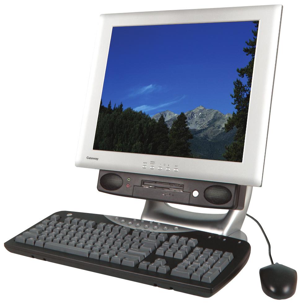
1 Gateway Profile 4 service guide Customizing Troubleshooting
2
3 Contents Replacing Components in Your Gateway Profile About this guide Preparing your work space Preventing static electricity discharge Preparing your computer Replacing drives Replacing the diskette drive Replacing the optical drive Replacing the hard drive Replacing the Mini PCI card Installing or replacing DIMM memory Replacing the fan Replacing the LCD panel Replacing the LCD panel inverter board Replacing the system board i
4 ii

5 Replacing Components in Your Gateway Profile 4 About this guide Use this service guide to help plan your maintenance tasks for the Gateway Profile 4. All tasks covered in this guide can be performed by a field technician without jeopardizing your computer s warranty. For information on your computer s general maintenance, technical support, safety notices, and regulatory notices, see your Gateway user s guide. If you have suggestions regarding the content of this guide, send an with the subject Service Guide Comments to channel.services@gateway.com Gateway, Inc. All rights reserved. Gateway, Gateway Country, the Gateway stylized logo, and the black-and-white spot design are trademarks or registered trademarks of Gateway, Inc. in the United States and other countries. All other brands and product names are trademarks or registered trademarks of their respective companies. 1
6 Thank you for purchasing this Factory Service Manual CD/DVD from servicemanuals4u.com. Please check out our ebay auctions for more great deals on Factory Service Manuals: servicemanuals4u
7 Replacing Components in Your Gateway Profile 4 Preparing your work space Before performing maintenance on your computer, make sure that your work space and your computer are correctly prepared. Wear a grounding (ESD) wrist strap. Use a grounded or dissipative work mat. Use a stable and strong table. Make sure that the table top is large enough to hold each component as you remove it. Use bright lighting to make part identification easier. Keep your work surface free from clutter and dust that may damage components. Use a magnetized screwdriver for removing screws. As you remove components and screws, lay them toward the back of your work surface (behind your computer) or far enough to the side that your arms do not accidentally brush components or screws onto the floor. To help keep track of screws, try the following: Place each component s screws in their own section of a parts sorter. Place each component s screws next to the component on your work surface. When you place flat-headed screws on your work surface, stand them on their heads to prevent the screws from rolling off the table. 2
8 Preventing static electricity discharge Preventing static electricity discharge The components inside your computer are extremely sensitive to static electricity, also known as electrostatic discharge (ESD). Caution ESD can permanently damage electrostatic discharge-sensitive components in your computer. Prevent ESD damage by following ESD guidelines every time you open the computer case. Warning To avoid exposure to dangerous electrical voltages and moving parts, turn off your computer and unplug the power cord and modem cable before opening the case. Before opening the computer case, follow these guidelines: Turn off the computer power. Wear a grounding wrist strap (available at most electronics stores) and attach it to a bare metal part of your workbench or other grounded connection. Warning To prevent risk of electric shock, do not insert any object into the vent holes of the power supply. Touch a bare metal surface on your workbench or other grounded object. Unplug the power cord and modem and network cables. Before working with computer components, follow these guidelines: Avoid static-causing surfaces such as carpeted floors, plastic, and packing foam. Remove components from their antistatic bags only when you are ready to use them. Do not lay components on the outside of antistatic bags because only the inside of the bags provide electrostatic protection. Avoid touching the edge connectors and components on the Mini-PCI cards. Never slide Mini-PCI cards or components over any surface. 3
9 Replacing Components in Your Gateway Profile 4 Preparing your computer Warning To avoid exposure to dangerous electrical voltages and moving parts, turn off your computer, then unplug the power cord and modem cable before opening the case. To prepare your computer: 1 Turn off your computer. 2 Following all static electricity discharge precautions, disconnect the power cord and all other external cables. 3 Press the power button to drain any residual power from your computer. Replacing drives Use the procedures in this section to replace the: Diskette drive Optical drive Hard drive Tools you need to complete these tasks: Phillips screwdriver 4
10 Replacing drives Replacing the diskette drive The removable drive pack contains the diskette drive, drive adapter card, and an optical drive. To replace the diskette drive: 1 Turn off the computer and prepare it by following the instructions in Preparing your computer on page 4. 2 Remove the two retaining screws located on either side of the Microsoft Certificate of Authenticity label on the back of your computer. Screws 5
11 Replacing Components in Your Gateway Profile 4 3 Slide the drive pack forward, then down. 4 Disconnect the two drive cables from the drive adapter card. Note the location and orientation of each cable. You will reconnect these cables later. 6

12 Replacing drives 5 Disconnect the diskette drive cable from the ZIF connector on the drive adapter card. 7

13 Replacing Components in Your Gateway Profile 4 6 Remove the four screws that secure the diskette drive to the drive pack. Screws Screws 8
14 Replacing drives 7 Remove the old diskette drive. 8 Insert the new diskette drive and secure it with the four screws removed in Step 6. 9

15 Replacing Components in Your Gateway Profile 4 9 Connect the diskette drive cable, making sure that it is fully seated in the ZIF connector. 10 Connect the drive cables to the drive adapter card on the drive pack using the notes you made in Step 4. The drive cables and connectors are keyed, which means that they can only be plugged in one way. 11 Push the cables carefully up into the top of the drive bay. 10
16 Replacing drives 12 Align the tabs on the drive pack with the notches on the drive bay, then slide the drive pack back until it is flush with the front of the case. Tabs 13 Secure the drive pack with the two screws removed in Step 2. 11
17 Replacing Components in Your Gateway Profile 4 Replacing the optical drive The removable drive pack contains the diskette drive, drive adapter card, and an optical drive. The optical drive may be a CD, DVD, or recordable drive. To replace the optical drive: 1 Turn off the computer and prepare it by following the instructions in Preparing your computer on page 4. 2 Remove the two retaining screws located on either side of the Microsoft Certificate of Authenticity label on the back of your computer. Screws 12
18 Replacing drives 3 Slide the drive pack forward, then down. 4 Disconnect the two drive cables from the drive adapter card. Note the location and orientation of each cable. You will reconnect these cables later. 13
19 Replacing Components in Your Gateway Profile 4 5 Remove the four screws that secure the optical drive to the drive pack. Left Side Screw Screw Right Side Screw Screw 14
20 Replacing drives 6 Slide the optical drive out of the drive pack. 7 Slide in the new optical drive and secure it with the four screws removed in Step 5. 8 Connect the drive cables to the drive adapter card on the drive pack using the notes you made in Step 4. The drive cables and connectors are keyed, which means that they can only be plugged in one way. 15
21 Replacing Components in Your Gateway Profile 4 9 Push the cables carefully up into the top of the drive bay. 10 Align the tabs on the drive pack with the notches on the drive bay, then slide the drive pack back until it is flush with the front of the case. Tabs 11 Secure the drive pack with the two screws removed in Step 2. 16
22 Replacing drives Replacing the hard drive Use this procedure to replace the hard drive. Tips & Tricks For more stability, place your computer face down to perform this procedure. Avoid scratching the computer display by placing it on a towel or other non-abrasive surface. To replace the hard drive: 1 Turn off the computer and prepare it by following the instructions in Preparing your computer on page 4. 2 Remove the two screws that secure the access panel to the back of the computer case. Screws 17
23 Replacing Components in Your Gateway Profile 4 3 With your hands positioned on each side of the case, swing the access panel up and away from the case and set the access panel aside. 4 Unsnap the two hard drive cage tabs. 5 Remove the hard drive cage from your computer. 18
24 Replacing drives 6 Disconnect the drive cable and power cable. Note the location and orientation of each cable. You will reconnect these cables later. 19


25 Replacing Components in Your Gateway Profile 4 7 Remove the four screws that secure the drive to the hard drive cage. Screws Screws 8 Remove the drive. 20
26 Replacing drives 9 Make sure that the jumpers on the new drive are set the same as the jumpers on the drive you are replacing. Jumpers 10 Insert the new drive into the hard drive cage and secure it with the four screws removed in Step Connect the drive cable and power cable to the drive using the notes you made in Step Align the single hard drive cage tab into the case notch, then swing the hard drive cage down until the two hard drive cage tabs on the other side snap into place. 21
27 Replacing Components in Your Gateway Profile 4 13 Make sure that all of the internal cables are arranged inside the case so they will not be pinched when you close the case. 14 Align the access panel tabs into the case notches. Access panel tabs 15 Swing the access panel down into place and secure it with the two screws removed in Step 2. 22
28 Replacing the Mini PCI card Replacing the Mini PCI card The modem in your computer is a Mini PCI card. If you need to install a new Mini PCI card, you must first remove the existing card. Warning Replace the Mini PCI card with only Gateway-approved cards. Tools you need to complete this task: Phillips screwdriver Tips & Tricks For more stability, place your computer face down to perform this procedure. Avoid scratching the computer display by placing it on a towel or other non-abrasive surface. 23
29 Replacing Components in Your Gateway Profile 4 To replace the Mini PCI card: 1 Turn off the computer and prepare it by following the instructions in Preparing your computer on page 4. 2 Remove the two screws that secure the access panel to the back of the computer case. Screws 24
30 Replacing the Mini PCI card 3 With your hands positioned on each side of the case, swing the access panel up and away from the case and set the access panel aside. 4 Unsnap the two hard drive cage tabs. 25
31 Replacing Components in Your Gateway Profile 4 5 Remove the hard drive cage from your computer. 6 Disconnect the drive cable and power cable and set the drive cage aside. Note the location and orientation of each cable. You will reconnect these cables later. 26


32 Replacing the Mini PCI card 7 Press outward on both of the retaining clips holding the Mini-PCI card until the card tips up at an angle. 8 Remove the Mini-PC card. 27

33 Replacing Components in Your Gateway Profile 4 9 Remove the cable from the Mini-PCI card. 10 Connect the cable to the new Mini-PCI card. 28


34 Replacing the Mini PCI card 11 Carefully press the new Mini-PCI card into the card slot. The card must be fully seated in the slot before the retaining clips will snap into place. 12 Connect the drive cable and power cable to the hard drive using the notes you made in Step Align the single hard drive cage tab into the case notch, then swing the hard drive cage down until the two hard drive cage tabs on the other side snap into place. 29
35 Replacing Components in Your Gateway Profile 4 14 Make sure that all of the internal cables are arranged inside the case so they will not be pinched when you close the case. 15 Align the access panel tabs into the case notches. Access panel tabs 16 Swing the access panel down into place and secure it with the two screws removed in Step 2. 30
36 Installing or replacing DIMM memory Installing or replacing DIMM memory Important Use only DDR266 DIMM memory. Tools you need to complete this task: Phillips screwdriver Tips & Tricks For more stability, place your computer face down to perform this procedure. Avoid scratching the computer display by placing it on a towel or other non-abrasive surface. 31
37 Replacing Components in Your Gateway Profile 4 To install or replace DIMM memory: 1 Turn off the computer and prepare it by following the instructions in Preparing your computer on page 4. 2 Remove the two screws that secure the access panel to the back of the computer case. Screws 32

38 Installing or replacing DIMM memory 3 With your hands positioned on each side of the case, swing the access panel up and away from the case and set the access panel aside. 4 Find the memory module banks, sometimes called add-in slots, on your system board. Memory modules 33
39 Replacing Components in Your Gateway Profile 4 5 If you are removing a memory module from the memory module bank, gently pull the plastic tabs away from the sides of the memory module and remove it. - OR - If you are adding a memory module to an empty memory module bank, gently pull the plastic tabs away from the sides of the memory module bank. 6 Align the notch on the new memory module with the notch on the memory module bank and press firmly into the bank. The tabs on the sides of the memory module should secure the memory module automatically. When the module locks into place, you hear a click. 7 Make sure that all of the internal cables are arranged inside the case so they will not be pinched when you close the case. 34
40 Installing or replacing DIMM memory 8 Align the access panel tabs into the case notches. Access panel tabs 9 Swing the access panel down into place and secure it with the two screws removed in Step Reconnect the external cables and power cord. 11 Turn on your computer. Windows starts and the Windows desktop appears. 12 In Windows XP, click Start, Control Panel, then click Performance and Maintenance (if in Category View). Click/Double-click System. The amount of memory in your computer is shown at the bottom of the System Properties window in the General tab. - OR - In Windows 2000, right-click the My Computer icon, then click Properties. The amount of memory in your computer is shown at the bottom of the System Properties window in the General tab. 35
41 Replacing Components in Your Gateway Profile 4 Replacing the fan Tools you need to complete this task: Phillips screwdriver Tips & Tricks For more stability, place your computer face down to perform this procedure. Avoid scratching the computer display by placing it on a towel or other non-abrasive surface. 36
42 Replacing the fan To replace the fan: 1 Turn off the computer and prepare it by following the instructions in Preparing your computer on page 4. 2 Remove the two screws that secure the access panel to the back of the computer case. Screws 37

43 Replacing Components in Your Gateway Profile 4 3 With your hands positioned on each side of the case, swing the access panel up and away from the case and set the access panel aside. 4 Remove the four screws that secure the fan to the heatsink. Screws Screws 38
44 Replacing the fan 5 Disconnect the fan power cable. Note the location and orientation of the cable. You will reconnect this cable later. 39


45 Replacing Components in Your Gateway Profile 4 6 Remove the old fan. 7 Secure the new fan to the heatsink with the four screws removed in Step 4. 40
46 Replacing the fan 8 Connect the fan power cable using the notes you made in Step 5. 9 Make sure that all of the internal cables are arranged inside the case so they will not be pinched when you close the case. 10 Align the access panel tabs into the case notches. Access panel tabs 11 Swing the access panel down into place and secure it with the two screws removed in Step 2. 41
47 Replacing Components in Your Gateway Profile 4 Replacing the LCD panel Tools you need to complete this task: Phillips screwdriver Flat-blade screwdriver To replace the LCD panel: 1 Turn off the computer and prepare it by following the instructions in Preparing your computer on page 4. 2 Lay the computer down on its back. 42
48 Replacing the LCD panel 3 Starting at the bottom center of the LCD panel bezel, carefully work your fingers under the plastic to pry the bezel away from the LCD panel. Work your fingers between the LCD glass and the bezel, not underneath the outside of the bezel. 4 Continue to work your fingers around each side of the screen while carefully prying the plastic tabs on the bezel away from the LCD panel. Warning Avoid excessively twisting or bending the bezel, because the bezel s plastic tabs may break. 43
49 Replacing Components in Your Gateway Profile 4 5 Remove the four screws that hold the LCD panel to the case. Warning Be careful while handling the LCD panel, and do not touch the LCD screen with any sharp object. Screws 6 Carefully tilt the bottom of the LCD panel slightly away from the case to access the cables behind the panel. 44
50 Replacing the LCD panel 7 Unplug the cable from the side of the inverter board closest to you (nearest the open side of the tilted LCD panel). 8 Tilt the LCD panel up further and unplug the other cable from the inverter board, then unplug the scaler board connector from the LCD panel. Scaler board Inverter board 45
51 Replacing Components in Your Gateway Profile 4 9 Remove the LCD panel from the computer. Tips & Tricks Mark or label the back of the removed panel as defective to prevent confusion with the new panel. 10 Place the new LCD panel onto the computer. 11 Reattach the scaler board cable to the LCD panel. 12 On the side of the inverter board closest to the top of the LCD panel, connect: The pink and white-wired plug to the connector on the left. The blue and black-wired plug to the connector on the right. Tips & Tricks To make it easier to plug the cables into the connectors, bend the wires near the plug so the plug is at a 90 angle to the wires. 13 On the side of the inverter board closest to the bottom of the LCD panel, connect: The pink and white-wired plug to the connector on the left. The blue and black-wired plug to the connector on the right. Warning The connectors should easily press into place. If you have difficulty attaching a connector, it may be turned upside-down. Turn the connector over and try again. 14 Press the LCD panel into place, and make sure that all cables are safely inside the computer behind the LCD panel. If you have difficulty pressing the LCD panel back into place, first press the top of the panel into place, then press the bottom forward and down. 15 Attach the LCD panel with the four screws, then set the computer upright. 16 Plug in the power cord, then turn on the computer to make sure that the display has been repaired. If the display appears to be working, turn off the computer and lay the computer down on its back again. 46
52 Replacing the LCD panel 17 Align the plastic bezel s tabs with the tab slots on the computer, then firmly press the bezel into place. Make sure all four edges are correctly attached and that the bezel has a tight fit. 47
53 Replacing Components in Your Gateway Profile 4 Replacing the LCD panel inverter board Tools you need to complete this task: Phillips screwdriver To replace the LCD panel inverter board: 1 Turn off the computer and prepare it by following the instructions in Preparing your computer on page 4. 2 Lay the computer down on its back. 3 Starting at the bottom center of the LCD panel bezel, carefully work your fingers under the plastic to pry the bezel away from the LCD panel. Work your fingers between the LCD glass and the bezel, not underneath the outside of the bezel. 48


54 Replacing the LCD panel inverter board 4 Continue to work your fingers around each side of the screen while carefully prying the plastic tabs on the bezel away from the LCD panel. Warning Avoid excessively twisting or bending the bezel, because the bezel s plastic tabs may break. 49

55 Replacing Components in Your Gateway Profile 4 5 Remove the four screws that hold the LCD panel to the case. Warning Be careful while handling the LCD panel, and do not touch the LCD screen with any sharp object. Screws 6 Carefully tilt the bottom of the LCD panel slightly away from the case to access the cables behind the panel. 50


56 Replacing the LCD panel inverter board 7 Unplug the cable from the side of the inverter board closest to you (nearest the open side of the tilted LCD panel). 8 Tilt the LCD panel up further and unplug the other cable from the inverter board, then unplug the scaler board connector from the LCD panel. Scaler board Inverter board 9 Remove the LCD panel from the computer and set it aside. 51

57 Replacing Components in Your Gateway Profile 4 10 Remove the two mounting screws on the inverter board. Screw Screw 52

58 Replacing the LCD panel inverter board 11 Turn the inverter board over, then unplug the cable that connects the inverter board to the scaler board. 12 Remove the inverter board from the computer. Tips & Tricks Mark or label the removed board as defective to prevent confusion with the new board. 13 Plug the cable from the scaler board into the new inverter board. 14 Hold the new inverter board by its edges and align it with the screw holes on the computer, then attach the two screws to the new board. Warning Do not press or apply pressure to the inverter board s components or plastic shields. 15 Place the LCD panel back onto the computer. 16 Reattach the scaler board cable to the LCD panel. 53
59 Replacing Components in Your Gateway Profile 4 17 On the side of the inverter board closest to the top of the LCD panel, connect: The pink and white-wired plug to the connector on the left. The blue and black-wired plug to the connector on the right. Tips & Tricks To make it easier to plug the cables into the connectors, bend the wires near the plug so the plug is at a 90 angle to the wires. 18 On the side of the inverter board closest to the bottom of the LCD panel, connect: The pink and white-wired plug to the connector on the left. The blue and black-wired plug to the connector on the right. Warning The connectors should easily press into place. If you have difficulty attaching a connector, it may be turned upside-down. Turn the connector over and try again. 19 Press the LCD panel into place, and make sure that all cables are safely inside the computer behind the LCD panel. If you have difficulty pressing the LCD panel back into place, first press the top of the panel into place, then press the bottom forward and down. 20 Attach the LCD panel with the four screws, then set the computer upright. 21 Plug in the power cord, then turn on the computer to make sure that the display has been repaired. If the display appears to be working, turn off the computer and lay the computer down on its back again. 54

60 Replacing the LCD panel inverter board 22 Align the plastic bezel s tabs with the tab slots on the computer, then firmly press the bezel into place. Make sure all four edges are correctly attached and that the bezel has a tight fit. 55

61 Replacing Components in Your Gateway Profile 4 Replacing the system board Tools you need to complete this task: Phillips screwdriver Flat-blade screwdriver To replace the system board: 1 Turn off the computer and prepare it by following the instructions in Preparing your computer on page 4. 2 Remove the two retaining screws located on either side of the Microsoft Certificate of Authenticity label on the back of your computer. Screws 56


62 Replacing the system board 3 Slide the drive pack forward, then down. 4 Disconnect the two drive cables from the drive adapter card and set the drive pack aside. Note the location and orientation of each cable. You will reconnect these cables later. 57

63 Replacing Components in Your Gateway Profile 4 5 Remove the two screws that secure the access panel to the back of the computer case. Screws 6 With your hands positioned on each side of the case, swing the access panel up and away from the case and set the access panel aside. 58

64 Replacing the system board 7 Unsnap the two hard drive cage tabs. 8 Remove the hard drive cage from your computer. 59

65 Replacing Components in Your Gateway Profile 4 9 Disconnect the drive cable and power cable. Note the location and orientation of each cable. You will reconnect these cables later. 60

66 Replacing the system board 10 Press the PC Card eject button so the eject button is extended. PC Card eject button 11 Pull off the rubber eject button cover, then push the PC Card eject button back in so it is flush with the system case. 61

67 Replacing Components in Your Gateway Profile 4 12 Disconnect the modem cable from the case cover. 62

68 Replacing the system board 13 Disconnect the fan power cable. Note the location and orientation of the cable. You will reconnect this cable later. 63

69 Replacing Components in Your Gateway Profile 4 14 Remove the four heatsink screws. Screws Screws 64
70 Replacing the system board 15 Gently move the heat sink side to side to make sure that the seal on the processor is loosened, then swing the heatsink up and away from the computer. 65

71 Replacing Components in Your Gateway Profile 4 16 Remove the six back case cover screws. Screws 17 Place your computer face down. Avoid scratching the computer display by placing it on a towel or other non-abrasive surface. 66


.")
72 Replacing the system board 18 Use a flat-blade screwdriver to push out the four side screw caps from inside the case, then use the screwdriver to remove the screw caps (two on each side of the case). Screw caps Screw caps 67
.")
73 Replacing Components in Your Gateway Profile 4 19 Use a Philips screwdriver to remove the four case cover side screws (two on each side of the case). Screws 68


74 Replacing the system board 20 Push up slightly on the stand so you can release the two case retaining tabs on the bottom of the computer. Bottom case retaining tabs 21 Press in on the case cover to release the six case retaining tabs. 69
75 Replacing Components in Your Gateway Profile 4 22 Lift the case cover straight up, then set it aside. 70
76 Replacing the system board 23 Disconnect the hard drive, power, and LED cables from the system board. Disconnect the speaker and headphone/microphone jack cables from the audio card. Note the location and orientation of each cable. You will reconnect these cables later. Hard drive cable Power cable Headphone/Microphone jack cable LED cable Speaker cables 71

77 Replacing Components in Your Gateway Profile 4 24 Remove the five screws holding the hard drive suspension plate to the system board, then remove the plate. Hard drive suspension plate Screws 72

78 Replacing the system board 25 Remove the two screws holding the card retention plate to the computer chassis, then remove the plate. Card retention plate Screws 73

79 Replacing Components in Your Gateway Profile 4 26 Remove the three screws securing the two gray card brackets to the system board. Screw Screws 27 Remove the two gray card brackets. 28 Remove the three cards from the system board. Note each card s location and orientation. You will reinstall these cards later. You can slightly seesaw the card end-to-end as you work it out of the slot, but do not bend the card sideways. 74
80 Replacing the system board 29 Disconnect the LCD video, LCD power, diskette drive, and optical drive cables from the system board. Note the location and orientation of each cable. You will reconnect these cables later. LCD video cable Optical drive cable LCD power cable Diskette drive cable 75

81 Replacing Components in Your Gateway Profile 4 30 Remove the five additional system board retaining screws. Screws Screws 76

82 Replacing the system board 31 Lift the system board away from the computer. 32 Secure the new system board to the computer with the five screws removed in Step

83 Replacing Components in Your Gateway Profile 4 33 Connect the LCD video, LCD power, diskette drive, and optical drive cables to the system board using the notes you made in Step 29. LCD video cable Optical drive cable LCD power cable Diskette drive cable 34 Secure the two card brackets to the system board with the three screws removed in Step Insert the three cards into the slots using the notes you made in Step 28. You can slightly seesaw the card end-to-end as you insert it into the slot, but do not bend the card sideways. 36 Secure the card retention plate to the computer chassis with the two screws removed in Step

84 Replacing the system board 37 Secure the hard drive suspension plate to the system board with the five screws removed in Step Connect the hard drive, power, and LED cables to the system board, then connect the speaker and headphone/microphone jack cable to the audio card using the notes you made in Step 23. Hard drive cable Power cable Headphone/Microphone jack cable LED cable Speaker cables 79


85 Replacing Components in Your Gateway Profile 4 39 Replace the case cover making sure that the case retaining tabs snap into place. 40 Replace the four side screws and screw caps removed in Step 18 and Step Replace the six back case cover screws removed in Step Connect the modem cable. 80

86 Replacing the system board 43 Align the heatsink tab into the slot on the system board and swing the heatsink back into place, then secure the heatsink with the four screws removed in Step Connect the fan power cable. 45 Connect the drive cable and power cable to the hard drive pack using the notes you made in Step 9. 81
87 Replacing Components in Your Gateway Profile 4 46 Align the single hard drive cage tab into the case notch, then swing the hard drive cage down until the two hard drive cage tabs on the other side snap into place. 47 Make sure that all of the internal cables are arranged inside the case so they will not be pinched when you close the case. 48 Replace the PC Card eject button cover. 82

88 Replacing the system board 49 Align the access panel tabs into the case notches. Access panel tabs 50 Swing the access panel down into place and secure it with the two screws removed in Step Return the computer to the upright position. 52 Connect the drive cables to the drive adapter card on the drive pack using the notes you made in Step 4. The drive cables and connectors are keyed, which means that they can only be plugged in one way. 53 Push the cables carefully up into the top of the drive bay. 83

89 Replacing Components in Your Gateway Profile 4 54 Align the tabs on the drive pack with the notches on the drive bay, then slide the drive pack back until it is flush with the front of the case. Tabs 55 Secure the drive pack with the two screws removed in Step 2. 84
90

91 MAN US PFL4 SERVICE GDE R2 10/03
Replacing the Gateway M405 Keyboard
 Replacing the Gateway M405 Keyboard This package includes a replacement keyboard for your Gateway M405 notebook and these printed instructions. Tools you need You need a small Phillips and a small flat-blade
To connect the AC adapter:
 Replacing the AC Adapter Replacing the AC Adapter 3 Plug the power cord into a wall outlet. The power indicator turns on. To connect the AC adapter: Connect the power cord to the AC adapter. Power indicator
Installing a New Solo 1150 Hard Drive
 Installing a New Solo 1150 Hard Drive This package includes a new hard drive kit for your Solo 1150 notebook computer and these printed instructions. Tools you need You will need a small Phillips screwdriver
Replacing the Gateway M275 Keyboard
 Replacing the Gateway M275 Keyboard This package includes a replacement keyboard for your Gateway M275 notebook and these printed instructions. Tools you need You need a small Phillips screwdriver and
Replacing the Gateway M305 Optical Drive
 Replacing the Gateway M305 Optical Drive This package includes an optical drive, such as a CD or DVD drive, for your Gateway M305 notebook and these printed instructions. Installing a replacement drive
Replacing the Gateway 200ARC Keyboard
 Replacing the Gateway 200ARC Keyboard Replacing the Gateway 200ARC Keyboard This package includes a replacement keyboard for your Gateway 200ARC notebook and these printed instructions. Tools you need
Thank you for purchasing this Factory Service Manual CD/DVD from servicemanuals4u.com.
 Thank you for purchasing this Factory Service Manual CD/DVD from servicemanuals4u.com. Please check out our ebay auctions for more great deals on Factory Service Manuals: servicemanuals4u Dell Latitude
Removing and Replacing Parts
 Removing and Replacing Parts Preparing to Work Inside the Computer Recommended Tools Screw Identification System Components Hard Drive Fixed Optical Drive Media Bay Devices Memory Modules Mini PCI Card
Thank you for purchasing this Factory Service Manual CD/DVD from servicemanuals4u.com.
 Thank you for purchasing this Factory Service Manual CD/DVD from servicemanuals4u.com. Please check out our ebay auctions for more great deals on Factory Service Manuals: servicemanuals4u Dell Inspiron
Dell Inspiron XPS and Inspiron 9100 Service Manual
 Dell Inspiron XPS and Inspiron 9100 Service Manual Dell Inspiron XPS and Inspiron 9100 Service Manual Before You Begin Memory Module, Mini PCI Card, and Devices System Components Subwoofer Bluetooth Card
Dell Latitude C800 Service Manual
 Dell Latitude C800 Service Manual Dell Latitude C800 Service Manual Before You Begin Preparing to Work Inside the Computer Recommended Tools Screw Identification Removing and Replacing Parts System Components
Dell XPS L702X Service Manual
 Dell XPS L702X Service Manual Regulatory model: P09E series Regulatory type: P09E002 Notes, Cautions, and Warnings NOTE: A NOTE indicates important information that helps you make better use of your computer.
Upgrading and Servicing Guide
 Upgrading and Servicing Guide The information in this document is subject to change without notice. Hewlett-Packard Company makes no warranty of any kind with regard to this material, including, but not
Upgrading and Servicing Guide
 Upgrading and Servicing Guide The only warranties for Hewlett-Packard products and services are set forth in the express statements accompanying such products and services. Nothing herein should be construed
Dell Inspiron N5110 Service Manual
 Dell Inspiron N5110 Service Manual Regulatory model: P17F Regulatory type: P17F001 Notes, Cautions, and Warnings NOTE: A NOTE indicates important information that helps you make better use of your computer.
Serial ATA Hot Swap Drive Cage Upgrade Kit for: Intel Server Chassis SC5200 Intel Server Chassis SC5250-E
 Serial ATA Hot Swap Drive Cage Upgrade Kit for: Intel Server Chassis SC5200 Intel Server Chassis SC5250-E A Guide for Technically Qualified Assemblers of Intel Identified Subassemblies/Products Order Number:
Dell Latitude V710/V740 Service Manual
 Dell Latitude V710/V740 Service Manual Dell Latitude V710/V740 Service Manual Before You Begin Preparing to Work Inside the Computer Recommended Tools Computer Orientation Screw Identification System Components
Dell Latitude C800 SERVICE MANUAL. support.dell.com
 Dell Latitude C800 SERVICE MANUAL www.dell.com support.dell.com Dell Latitude C800 SERVICE MANUAL www.dell.com support.dell.com Notes, Notices, and Cautions NOTE: A NOTE indicates important information
Thank you for purchasing this Factory Service Manual CD/DVD from servicemanuals4u.com.
 Thank you for purchasing this Factory Service Manual CD/DVD from servicemanuals4u.com. Please check out our ebay auctions for more great deals on Factory Service Manuals: servicemanuals4u Dell Inspiron
Chapter 4 Replacement Procedures
 Chapter 4 Replacement Procedures 4 4-ii Satellite P30 Series Maintenance Manual Chapter 4 Contents 4.1 General... 4-1 4.2 Battery... 4-7 4.3 PC Card... 4-8 4.4 HDD... 4-10 4.5 Optical Drive Module... 4-12
Upgrading and Servicing Guide
 Upgrading and Servicing Guide The only warranties for Hewlett-Packard products and services are set forth in the express statements accompanying such products and services. Nothing herein should be construed
Upgrading and Servicing Guide
 Upgrading and Servicing Guide Copyright Information The only warranties for Hewlett-Packard products and services are set forth in the express statements accompanying such products and services. Nothing
Dell XPS 14z Owner s Manual
 Dell XPS 14z Owner s Manual Computer model: L412z Regulatory model: P24G series Regulatory type: P24G001 Notes, Cautions, and Warnings NOTE: A NOTE indicates important information that helps you make better
Upgrading and Servicing Guide
 Upgrading and Servicing Guide The information in this document is subject to change without notice. Hewlett-Packard Company makes no warranty of any kind with regard to this material, including, but not
Upgrading and Servicing Guide
 Upgrading and Servicing Guide Copyright Information The only warranties for Hewlett-Packard products and services are set forth in the express statements accompanying such products and services. Nothing
Installing System Board Options
 CHAPTER 8 Installing System Board Options This section describes how to install the following options: Expansion cards Memory modules Microprocessor This section also includes instructions for replacing
Installing the Cisco ADE 2130 and 2140 Series Appliance Hardware Options
 CHAPTER 4 Installing the Cisco ADE 2130 and 2140 Series Appliance Hardware Options This chapter provides instructions for installing, replacing, and removing various hardware options in your Cisco ADE
Thank you for purchasing this Factory Service Manual CD/DVD from servicemanuals4u.com.
 Thank you for purchasing this Factory Service Manual CD/DVD from servicemanuals4u.com. Please check out our ebay auctions for more great deals on Factory Service Manuals: servicemanuals4u Dell Inspiron
Intel NUC Kit NUC8i7HNK & NUC8i7HVK User Guide. Intel NUC Kit NUC8i7HNK Intel NUC Kit NUC8i7HVK User Guide
 Intel NUC Kit NUC8i7HNK Intel NUC Kit NUC8i7HVK User Guide 1 Before You Begin CAUTIONS The procedures in this user guide assume familiarity with the general terminology associated with personal computers
Replacing the PanelMate Power Pro 1785 Series, PanelMate epro 7585x-8 and 7685x-8 Series Backlight Assembly
 Replacing the PanelMate Power Pro 1785 Series, PanelMate epro 7585x-8 and 7685x-8 Series Assembly Introduction The Replacement Kit provides a replacement backlight for the PanelMate Power Pro 1785 Series,
Dell XPS M1730 Service Manual
 Dell XPS M1730 Service Manual Model PP06XA www.dell.com support.dell.com Notes, Notices, and Cautions NOTE: A NOTE indicates important information that helps you make better use of your computer. NOTICE:
Installing and Upgrading Memory and Virtual Private Network Modules
 APPENDIX C Installing and Upgrading Memory and Virtual Private Network Modules This chapter tells how to install or upgrade memory and how to install a Virtual Private Network (VPN) module in your Cisco
4.1 General. 4 Replacement Procedures
 4.1 General This chapter explains how to disassemble the computer and replace Field Replaceable Units (FRUs). It may not be necessary to remove all the FRUs in order to replace one. The chart below is
Dell XPS M1530 Service Manual
 Dell XPS M1530 Service Manual Model PP28L www.dell.com support.dell.com Notes, Notices, and Cautions NOTE: A NOTE indicates important information that helps you make better use of your computer. NOTICE:
H4 Series Hardware Replacement Guide
 Machine type: 10059/7723 10060/7724 10068/7752 10080/3099/1194 10091/2558/1196 H4 Series Hardware Replacement Guide Version 3.0 2011.08 31500379 Hardware Replacement Guide Copyright Lenovo 2011. All rights
Replacement Instructions
 imac G5 Inverter, 20-inch Replacement Instructions Follow the instructions in this document carefully. Failure to follow these instructions could damage your equipment and void its warranty. Note: Online
Dell Precision 3430 Small Form Factor
 Dell Precision 3430 Small Form Factor USB Type-C card Installation Guide Regulatory Model: D11S Regulatory Type: D11S004 Notes, cautions, and warnings NOTE: A NOTE indicates important information that
Installation Guide. Copyright 2005 MSI Computer Corp.
 Installation Guide Copyright 2005 MSI Computer Corp. Overview: 1013 is shipped out as a barebone. Some of the components are equipped while some are not. This installation guide provides you with the information
Thank you for purchasing this Factory Service Manual CD/DVD from servicemanuals4u.com.
 Thank you for purchasing this Factory Service Manual CD/DVD from servicemanuals4u.com. Please check out our ebay auctions for more great deals on Factory Service Manuals: servicemanuals4u Dell Inspiron
Intel NUC Kit DN2820FYKH User Guide. Intel NUC Kit DN2820FYKH User Guide
 Intel NUC Kit DN2820FYKH User Guide 1 Before You Begin CAUTIONS The procedures in this user guide assume familiarity with the general terminology associated with personal computers and with the safety
Instructions for SVC-KIT-0020
 Kaleidescape, Inc. July 22, 2010 Instructions for SVC-KIT-0020 Title Time to complete 1U Server Power Supply Replacement 1 hour Procedure to complete Locate Parts and Tools Service Kit Parts Power supply
Intel NUC Kit D54250WYKH & D34010WYKH User Guide. Intel NUC Kit D54250WYKH Intel NUC Kit D34010WYKH User Guide
 Intel NUC Kit D54250WYKH Intel NUC Kit D34010WYKH User Guide 1 Before You Begin CAUTIONS The procedures in this user guide assume familiarity with the general terminology associated with personal computers
Intel NUC Kit NUC8i7HNK & NUC8i7HVK User Guide. Intel NUC Kit NUC8i7HNK Intel NUC Kit NUC8i7HVK. User Guide
 Intel NUC Kit NUC8i7HNK Intel NUC Kit NUC8i7HVK User Guide 1 Before You Begin CAUTIONS The procedures in this user guide assume familiarity with the general terminology associated with personal computers
Alienware Area-51 R5 Service Manual
 Alienware Area-51 R5 Service Manual Computer Model: Alienware Area-51 R5 Regulatory Model: D03X Regulatory Type: D03X002 Notes, cautions, and warnings NOTE: A NOTE indicates important information that
Intel NUC Kit DC53427HYE User Guide. Intel NUC Kit DC53427HYE
 Intel NUC Kit DC53427HYE User Guide 1 Before You Begin CAUTIONS The procedures in this user guide assume familiarity with the general terminology associated with personal computers and with the safety
Replacing the RAID Battery Backup Unit Assembly on Series 3 FireSIGHT 3500 Defense Centers, Version 5.x
 Replacing the RAID Battery Backup Unit Assembly on Series 3 FireSIGHT 3500 Defense Centers, Version 5.x Last Updated: December 4, 2014 Use these instructions to replace the RAID battery backup unit (BBU)
User Guide for NUC8i5BEK, NUC8i3BEK. Intel NUC Kit NUC8i5BEK Intel NUC Kit NUC8i3BEK. User Guide
 Intel NUC Kit NUC8i5BEK Intel NUC Kit NUC8i3BEK User Guide 1 Before You Begin CAUTIONS The steps in this guide assume you re familiar with computer terminology and with the safety practices and regulatory
User Guide. Intel NUC 8 Business, a Mini PC with Windows 10 NUC8i7HNKQC. Intel NUC 8 Enthusiast, a Mini PC with Windows 10 NUC8i7HVKVA
 Intel NUC 8 Business, a Mini PC with Windows 10 NUC8i7HNKQC Intel NUC 8 Enthusiast, a Mini PC with Windows 10 NUC8i7HVKVA User Guide 1 Before You Begin CAUTIONS The procedures in this user guide assume
Intel NUC Kit NUC7i7BNH Intel NUC Kit NUC7i5BNH Intel NUC Kit NUC7i3BNH
 Intel NUC Kit NUC7i7BNH Intel NUC Kit NUC7i5BNH Intel NUC Kit NUC7i3BNH User Guide 1 Before You Begin CAUTIONS The procedures in this user guide assume familiarity with the general terminology associated
Dell OptiPlex All-in-One. Stand Installation Guide
 Dell OptiPlex All-in-One Stand Installation Guide Notes, cautions, and warnings NOTE: A NOTE indicates important information that helps you make better use of your product. CAUTION: A CAUTION indicates
User Guide for NUC7CJYSAL. Intel NUC 7 Essential, a Mini PC with Windows 10 NUC7CJYSAL. User Guide
 Intel NUC 7 Essential, a Mini PC with Windows 10 NUC7CJYSAL User Guide 1 Before You Begin CAUTIONS The procedures in this guide assume familiarity with the general terminology associated with personal
User Guide. Intel NUC7 Home, a Mini PC with Windows 10 NUC7i5BNKP. Intel NUC7 Enthusiast, a Mini PC with Windows 10 NUC7i7BNKQ
 Intel NUC7 Home, a Mini PC with Windows 10 NUC7i5BNKP Intel NUC7 Enthusiast, a Mini PC with Windows 10 NUC7i7BNKQ User Guide 1 Before You Begin CAUTION The procedures in this guide assume familiarity with
Intel NUC7 Home, a Mini PC with Windows 10 NUC7i3BNHXF. Intel NUC7 Home, a Mini PC with Windows 10 NUC7i5BNHXF
 Intel NUC7 Home, a Mini PC with Windows 10 NUC7i3BNHXF Intel NUC7 Home, a Mini PC with Windows 10 NUC7i5BNHXF Intel NUC7 Enthusiast, a Mini PC with Windows 10 NUC7i7BNHXG User Guide 1 Before You Begin
User Guide for NUC7CJYSAL. Intel NUC 7 Essential, a Mini PC with Windows 10 NUC7CJYSAL. User Guide
 Intel NUC 7 Essential, a Mini PC with Windows 10 NUC7CJYSAL User Guide 1 Before You Begin CAUTIONS The steps in this guide assume you re familiar with computer terminology and with the safety practices
Dell Inspiron 660 Owner s Manual
 Dell Inspiron 660 Owner s Manual Computer model: Inspiron 660 Regulatory model: D11M Regulatory type: D11M002 Notes, Cautions, and Warnings NOTE: A NOTE indicates important information that helps you make
WEASEL N/B MAINTENANCE
 2. System Assembly & Disassembly 2.1 System View 2.1.1 Front View ❶ Microphone Connector ❷ Audio Input Connector ❸ Audio Output Connector ❹ Top Cover Latch ❹ ❶ ❸ ❷ 2.1.2 Left-Side View ❶ VGA Port ❷ S-Video
Intel NUC Kit NUC7i3BNHX1 with Intel Optane Memory. Intel NUC Kit NUC7i5BNHX1 with Intel Optane Memory
 Intel NUC Kit NUC7i3BNHX1 with Intel Optane Memory Intel NUC Kit NUC7i5BNHX1 with Intel Optane Memory Intel NUC Kit NUC7i7BNHX1 with Intel Optane Memory User Guide 1 Before You Begin CAUTIONS The procedures
Inspiron 22. Service Manual Series. Regulatory Model: W17B Regulatory Type: W17B001
 Inspiron 22 3000 Series Service Manual Regulatory Model: W17B Regulatory Type: W17B001 Notes, cautions, and warnings NOTE: A NOTE indicates important information that helps you make better use of your
Precision 3930 Rack. Zoom card Installation Guide. Regulatory Model: D24M Regulatory Type: D24M003
 Precision 3930 Rack Zoom card Installation Guide Regulatory Model: D24M Regulatory Type: D24M003 Notes, cautions, and warnings NOTE: A NOTE indicates important information that helps you make better use
HARMONi G3. Quick Start Guide for HARMONi G3. imac Processor/FireWire Upgrade
 HARMONi G3 imac Processor/FireWire Upgrade imac and Operating System Compatibility The HARMONi G3 imac processor/firewire upgrade is compatible only with imac 233, 266, and 333 MHz models (Revisions A-D);
Intel NUC Kit NUC5i3MYHE & NUC5i5MYHE User Guide. Intel NUC Kit NUC5i3MYHE Intel NUC Kit NUC5i5MYHE User Guide
 Intel NUC Kit NUC5i3MYHE Intel NUC Kit NUC5i5MYHE User Guide 1 Before You Begin CAUTIONS The procedures in this user guide assume familiarity with the general terminology associated with personal computers
Intel NUC Kit NUC7i7BNH, NUC7i5BNH & NUC7i3BNH User Guide. Intel NUC Kit NUC7i7BNH Intel NUC Kit NUC7i5BNH Intel NUC Kit NUC7i3BNH User Guide
 Intel NUC Kit NUC7i7BNH Intel NUC Kit NUC7i5BNH Intel NUC Kit NUC7i3BNH User Guide 1 Before You Begin CAUTIONS The procedures in this user guide assume familiarity with the general terminology associated
User Guide for NUC7i3DNHNC. Intel NUC7 Business, a Mini PC with Windows 10 NUC7i3DNHNC. User Guide
 Intel NUC7 Business, a Mini PC with Windows 10 NUC7i3DNHNC User Guide 1 Before You Begin CAUTIONS The steps in this guide assume you re familiar with computer terminology and with the safety practices
apple Service Source imac (USB 2.0) Updated 11 September Apple Computer, Inc. All rights reserved.
 Updated 11 September Apple Computer, Inc. All rights reserved.") apple Service Source imac (USB 2.0) Updated 11 September 2003 2003 Apple Computer, Inc. All rights reserved. imac (USB 2.0) - 1 apple Service Source Basics imac (USB 2.0) 2003 Apple Computer, Inc. All
apple Service Source imac (USB 2.0) Updated 11 September 2003 2003 Apple Computer, Inc. All rights reserved. imac (USB 2.0) - 1 apple Service Source Basics imac (USB 2.0) 2003 Apple Computer, Inc. All
OnePlus 5 Screen and Digitizer Assembly Replacement
 OnePlus 5 Screen and Digitizer Assembly Replacement Follow this guide to replace the screen and digitizer for the OnePlus 5. This replaces the screen as well as the frame it is attached to. Written By:
Maintaining and Troubleshooting Your E-4200 System
 Maintaining and Troubleshooting Your E-4200 System Maintaining and Troubleshooting Your E-4200 System Part #8503809 MAN US E-4200 TECH REF R0 10/98 In our effort to use nature s resources efficiently and
imac Intel 27" EMC 2639 Hard Drive
 imac Intel 27" EMC 2639 Hard Drive Replacement Replace the Hard Drive in your imac Intel 27" EMC 2639. Written By: Walter Galan ifixit CC BY-NC-SA www.ifixit.com Page 1 of 26 INTRODUCTION Replacing the
ALIENWARE AURORA SERVICE MANUAL 01/
 ALIENWARE AURORA SERVICE MANUAL 01/ 01 Notes, Cautions, and Warnings NOTE: A NOTE indicates important information that helps you make better use of your computer. CAUTION: A CAUTION indicates either potential
Replacing the Power Supply
 APPENDIX B This appendix includes information on how to replace the power supply for the Cisco AS550XM universal gateway and contains the following sections: Safety Recommendations, page B-1 Required Tools
CRESCENDO /7200 G3. Quick Start Guide for Crescendo /7200. Processor Upgrade Card for Power Macintosh 7200/8200 Computers
 CRESCENDO /7200 G3 Processor Upgrade Card for Power Macintosh 7200/8200 Computers Quick Start Guide for Crescendo /7200 System Compatibility At this printing, processor upgrade cards are compatible with
ThinkCentre Hardware Installation and Replacement Guide
 ThinkCentre Hardware Installation and Replacement Guide Note Before using this information and the product it supports, be sure to read and understand thesafety and Warranty Guide for this product and
Written By: John Sutton
 Replacing the fan on your HP g7-2275 dx. Written By: John Sutton ifixit CC BY-NC-SA www.ifixit.com Page 1 of 20 INTRODUCTION Laptop cooking your lap? This guide will walk you through replacing your fan.
apple Service Source ibook G4 (14.1 LCD) October 22, Apple Computer, Inc. All rights reserved.
 October 22, Apple Computer, Inc. All rights reserved.") apple Service Source ibook G4 (14.1 LCD) October 22, 2003 2003 Apple Computer, Inc. All rights reserved. apple Service Source Take Apart ibook G4 (14.1 LCD) 2003 Apple Computer, Inc. All rights reserved.
apple Service Source ibook G4 (14.1 LCD) October 22, 2003 2003 Apple Computer, Inc. All rights reserved. apple Service Source Take Apart ibook G4 (14.1 LCD) 2003 Apple Computer, Inc. All rights reserved.
FIELD REPLACEABLE UNIT DOCUMENTATION
 Satellite TM 1700 Series GENERAL INFORMATION Tools Required for Proper Disassembly and Reassembly: 1. Phillips Screwdriver (Size 1) 2. Flat head screwdriver (5mm) 3. Hex driver (5mm) 4. Case Separator
Motion LE1700 Tablet PC Hard Disk Drive Upgrade Procedure
 Motion LE1700 Tablet PC Hard Disk Drive Upgrade Procedure 2008 Motion Computing, Inc. All rights reserved. This document contains information protected by copyright. No part of this document may be reproduced
Reflowing Xbox 360 Motherboard
 Reflowing Xbox 360 Motherboard Reflow the solder on your Xbox 360's motherboard. Written By: Andrew Bookholt ifixit CC BY-NC-SA www.ifixit.com Page 1 of 31 INTRODUCTION Use this guide to reflow the solder
Presario 1200 Series Models: XL101-XL113, XL115, XL118-XL127. This section explains the removal and replacement procedures for the 1200XL unit.
 Removal Sequence Presario 1200 Series This section explains the removal and replacement procedures for the 1200XL unit. Serial Number Location Report the unit s serial number 1 to Compaq when requesting
User Guide. Intel NUC 8 Enthusiast, a Mini PC with Windows 10 NUC8i7BEKQA. Intel NUC 8 Home, a Mini PC with Windows 10 NUC8i5BEKPA
 Intel NUC 8 Enthusiast, a Mini PC with Windows 10 NUC8i7BEKQA Intel NUC 8 Home, a Mini PC with Windows 10 NUC8i5BEKPA User Guide 1 Before You Begin CAUTIONS The steps in this guide assume you re familiar
FIELD REPLACEABLE UNIT DOCUMENTATION. Satellite TM. A20 Series GENERAL INFORMATION. Tools Required for Proper Disassembly and Reassembly:
 GENERAL INFORMATION Tools Required for Proper Disassembly and Reassembly: 1. Phillips Screwdriver (Size 0&1) 2. 4mm Flat head Screwdriver 3. Case Separator 4. ESD Wrist Strap 5. ESD mats 6. Tweezers Before
Replacement Keyswitch Assembly
 Installation Instructions Replacement Keyswitch Assembly (Catalog No. 2711E-NKSW1) Applicable Terminals Use this replacement keyswitch with PanelView Terminals 2711-KA1, -KC1, -TA1, -TC1, -TA4, -TC4 and
Hardware Replacement Guide
 Hardware Replacement Guide Types 6491, 8013, 8702, 8706 Types 8716, 8970, 8972, 8976 Types 8980, 8982, 8986, 8992 Types 8994, 9266, 9276, 9278 Types 9282, 9286, 9288, 9374 Types 9378, 9380, 9384, 9628
Dell OptiPlex 7460 All-in-One. Intel Optane card installation guide
 Dell OptiPlex 7460 All-in-One Intel Optane card installation guide Notes, cautions, and warnings NOTE: A NOTE indicates important information that helps you make better use of your product. CAUTION: A
User Guide. Intel NUC 7 Home, a Mini PC with Windows 10 NUC7i5BNKP. Intel NUC 7 Enthusiast, a Mini PC with Windows 10 NUC7i7BNKQ
 Intel NUC 7 Home, a Mini PC with Windows 10 NUC7i5BNKP Intel NUC 7 Enthusiast, a Mini PC with Windows 10 NUC7i7BNKQ User Guide 1 Before You Begin CAUTION The steps in this guide assume you re familiar
Installing and Removing SDRAM and DRAM
 CHAPTER 4 This chapter explains how to remove and replace the main memory modules on the network processing engine or network services engine. For the location of the memory module you are replacing, find
Dell Precision M4600 Owner's Manual
 Dell Precision M4600 Owner's Manual Regulatory Model P13F Regulatory Type P13F001 Notes, Cautions, and Warnings NOTE: A NOTE indicates important information that helps you make better use of your computer.
XTM 1050 Replacement Parts Installation
 XTM 1050 Replacement Parts Installation Instructions to replace or install: Power Supply Chassis Fan Fiber Card 10 Gb Interface Module WARNING! Do not open the XTM 1050 or try to replace or install any
How to Assemble a Desktop PC
 How to Assemble a Desktop PC By Taylor Koch iii Table of Contents Introduction to Building a Desktop PC... 1 Preparation and Precautions... 3 PC Parts... 3 Basic Tools... 3 Safety Precautions... 3 Installing
Intel NUC Kit NUC6CAYS User Guide
 Intel NUC Kit NUC6CAYS User Guide Regulatory Model NUC6CAY 1 Before You Begin CAUTIONS The steps in this guide assume you re familiar with computer terminology and with the safety practices and regulatory
OptiPlex XE3 Tower. Remote Power Switch Installation Guide. Regulatory Model: D18M Regulatory Type: D18M005
 OptiPlex XE3 Tower Remote Power Switch Installation Guide Regulatory Model: D18M Regulatory Type: D18M005 Notes, cautions, and warnings NOTE: A NOTE indicates important information that helps you make
Removal and Installation8
 8 Screw Types 8-4 Top Cover Assembly 8-5 Left Hand Cover 8-6 Right Hand Cover 8-10 Front Panel Assembly 8-14 Left Rear Cover 8-15 Right Rear Cover 8-16 Extension Cover (60" Model only) 8-17 Media Lever
Written By: Sam Lionheart
 iphone SE Logic Board Replacement Use this guide to replace a faulty logic board in your iphone SE. Written By: Sam Lionheart ifixit CC BY-NC-SA www.ifixit.com Page 1 of 27 INTRODUCTION Use this guide
Written By: Walter Galan
 imac Intel 21.5" EMC 2428 CPU Replacement Replace the CPU in your imac Intel 21.5" EMC 2428. Written By: Walter Galan ifixit CC BY-NC-SA www.ifixit.com Page 1 of 33 INTRODUCTION Use this guide to upgrade
XPS 15 2-in-1. Service Manual. Computer Model: XPS Regulatory Model: P73F Regulatory Type: P73F001
 XPS 15 2-in-1 Service Manual Computer Model: XPS 15-9575 Regulatory Model: P73F Regulatory Type: P73F001 Notes, cautions, and warnings NOTE: A NOTE indicates important information that helps you make better
Intel NUC 7 Home, a Mini PC with Windows 10 NUC7i3BNHXF. Intel NUC 7 Home, a Mini PC with Windows 10 NUC7i5BNHXF
 Intel NUC 7 Home, a Mini PC with Windows 10 NUC7i3BNHXF Intel NUC 7 Home, a Mini PC with Windows 10 NUC7i5BNHXF Intel NUC 7 Enthusiast, a Mini PC with Windows 10 NUC7i7BNHXG User Guide 1 Before You Begin
Memory (RAM) Replacement Instructions. apple PowerBook (FireWire) Tools Required. Electrostatic Discharge (ESD)
 Replacement Instructions. apple PowerBook (FireWire) Tools Required. Electrostatic Discharge (ESD)") apple PowerBook (FireWire) Memory (RAM) Replacement Instructions Be sure to follow these instructions carefully. Failure to follow these instructions could result in damage to your equipment and may void
apple PowerBook (FireWire) Memory (RAM) Replacement Instructions Be sure to follow these instructions carefully. Failure to follow these instructions could result in damage to your equipment and may void
Oracle <Insert Picture Here>
 Slide 1 Oracle Slide 2 WZT-6509 version B Sun Fire Nehalem and Westmere Rack-Mount Server Installation and Replacement Welcome to the installation and replacement
PC9/P9 CPU Card Replacement
 Introduction These instructions explain how to replace the CPU card in the PC9 Industrial PC or the P9 PowerStation. They include steps for disassembling the unit, removing the old CPU card, installing
After completing this chapter, you will meet these objectives:
 3.0 Introduction Assembling computers is a large part of a technician's job. As a technician, you will need to work in a logical, methodical manner when working with computer components. As with any learned
Hardware Replacement Guide Types 8099, 8116, 8155, 8156 Types 8157, 8158, 8159, 8160 Types 8215, 9210, 9211
 Hardware Replacement Guide Types 8099, 8116, 8155, 8156 Types 8157, 8158, 8159, 8160 Types 8215, 9210, 9211 Hardware Replacement Guide Types 8099, 8116, 8155, 8156 Types 8157, 8158, 8159, 8160 Types 8215,
imac Intel 21.5" EMC 2389 Stand Replacement
 imac Intel 21.5" EMC 2389 Stand Replacement Replace a broken or cosmetically unappealing stand on the imac 2389 21.5 Written By: Aaron Cooke ifixit CC BY-NC-SA www.ifixit.com Page 1 of 30 INTRODUCTION