Sensitive Earth-fault Relay SPAJ 111 C. Product Guide
|
|
|
- Melvin Dalton
- 5 years ago
- Views:
Transcription
1
2
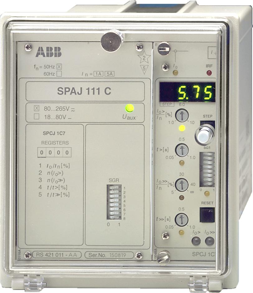
3 Issued: April 1999 Status: Update Version: C/ Data subject to change without notice Features Sensitive low-set neutral overcurrent stage with definite time characteristic High-set neutral overcurrent stage with definite time characteristic Output relay functions to be freely configured Flexible adaptation to different types of application 1 A and 5 A energizing inputs Serial interface for connecting the relay to a fibre-optic serial bus and further to a substation or network control system Digital display of setting values, neutral current measured, values recorded at relay operation, indications, etc. Powerful software support for parameterization and supervision of the relay Continuous hardware and software selfsupervision including auto-diagnosis Member of the SPACOM product family and ABB s Distribution Automation system CE marking according to the EC directive for EMC Application The sensitive earth-fault relay is designed to be used as a neutral current measuring feeder earth-fault relay, as generator interturn fault protection, as capacitor bank unbalance protection and rotor earth-fault protection. The sensitive earth-fault relay is suited for both primary and back-up earth-fault protection. The input impedance of the energizing circuit of the earth-fault relay is extremely low which means that the relay can also be energized from low output core-balance current transformers. Core-balance current transformers can be recommended when extremely sensitive earth-fault protection is required. The earth-fault relay can also be energized from a set of three phase current transformers connected in parallel, a so called residual current connection. 3
4 Design The sensitive earth-fault relay is a secondary relay which is connected to the current transformers of the object to be protected. When an earth fault occurs, the relay delivers an alarm signal, trips the circuit breaker or starts an external auto-reclose relay, depending on the application and the configuration of the relay. When the energizing current exceeds the set start value I 0 > of the low-set stage, the earthfault relay starts. When the set operate time t> expires, the relay operates. In the same way the high-set stage starts once the set start value I 0 >> is exceeded and, when the set operate time t>> expires, the relay operates. The start signal from the sensitive earth-fault relay is received as contact function. The start signal can be used, for instance, for blocking cooperating protection relays. The relay contains one optically isolated logic input for external incoming control signals, generally blocking signals. Data communication The relay is provided with a serial interface on the rear panel. By means of a bus connection module type SPA-ZC 17 or SPA-ZC 21 the relay can be connected to the fibre-optic SPA bus. The bus connection module type SPA-ZC 21 is powered from the host relay, whereas the bus connection module SPA- ZC 17 is provided with a built-in power unit, which can be fed from an external secured power source. The relay communicates with higher-level data acquisition and control systems over the SPA bus. Self-supervision The relay incorporates a sophisticated selfsupervision system with auto-diagnosis, which increases the availability of the relay and the reliability of the system. The selfsupervision system continuously monitors the hardware and the software of the relay. The system also supervises the operation of the auxiliary supply module and the voltages generated by the module. When the self-supervision system detects a permanent internal relay fault, the IRF indicator on the relay front panel is lit. At the same time the output relay of the self-supervision system operates and a fault message is transmitted to the higher-level system over the serial bus. Further, in most fault situations, a fault code is shown in the display of the protection relay module. The fault code indicates the type of the fault that has been detected. Auxiliary supply voltage The auxiliary supply of the relay is obtained from an internal plug-in type power supply module. Two auxiliary power module versions are available: type SPTU 240S1 for the supply voltage range V ac/dc and type SPTU 48S1 for the supply voltage range V dc. The power supply module forms the internal voltages required by the protection relay and the I/O module. 4
5 Technical data Table 1: Energizing inputs Terminals Rated current I n 1 A 5 A Thermal withstand continuously 4 A 20 A capability for 10 s 25 A 100 A for 1 s 100 A 500 A Dynamic current Half-wave value 250 A 1250 A withstand capability Input impedance <100 mω <20 mω Rated frequency f n, according to order 50 Hz or 60 Hz Table 2: Output contact ratings Type of contact Tripping Signalling Terminals 65-66, , , 77-78, Rated voltage 250 V ac/dc Thermal withstand Carry continuously 5 A 5 A capability Make and carry for 0.5 s 30 A 10 A Make and carry for 3 s 15 A 8 A Breaking capacity for dc, 220 V dc 1 A 0.15 A when the 110 V dc 3 A 0.25 A control/signalling circuit time constant L/R 40 ms, at the control voltages 48 V dc 5 A 1 A Table 3: Control input, communication and power supply External control input Terminals Control voltage level V dc or V ac Power consumption when input activated 2 20 ma Data communication Transmission mode Fibre-optic serial bus Data code ASCII Selectable data transfer rates 300, 1200, 2400, 4800 or 9600 Bd Fibre-optic bus for plastic fibre cables SPA-ZC 21BB connection module, for glass fibre cables SPA-ZC 21MM powered from the host relay Fibre-optic bus for plastic fibre cables SPA-ZC 17BB connection module with for glass fibre cables SPA-ZC 17MM a built-in power supply unit Auxiliary supply modules Power supply and I/O SPTU 240S V ac/dc modules and voltage SPTU 48S V dc ranges Power consumption under quiescent ~4 W conditions under operating conditions ~6 W 5
6 Technical data (cont d) Table 4: Relay module SPCJ 1C7 Low-set stage I 0 > Start current I 0 >, setting range % of I n Operate time t> s High-set stage I 0 >> Start current I 0 >>, setting range 1 200% of I n and, infinite Operate time t>> Table 5: Tests and standards Test voltages Dielectric test voltage (IEC ) 2.0 kv, 50 Hz, 1 min Interference tests Impulse test voltage (IEC ) Insulation resistance (IEC ) High-frequency (1 MHz) disturbance test (IEC ), common mode High-frequency (1 MHz) disturbance test (IEC ), differential mode Fast transients (IEC and IEC ), power supply inputs Fast transients (IEC and IEC ), other inputs Electrostatic discharge (IEC and IEC ), air discharge Electrostatic discharge (IEC and IEC ), contact discharge s 5 kv, 1.2/50 µs, 0.5 J >100 MΩ, 500 V dc 2.5 kv 1.0 kv 4 kv, 5/50 ns 2 kv, 5/50 ns Environmental conditions Service temperature range C Transport and storage temperature C range (IEC ) Damp heat test (IEC ) <95%, +40 C, 96 h Relative humidity (IEC ) 93 95%, +55 C, 6 cycles Degree of protection by enclosure IP 54 when flush mounted Weight 3 kg 8 kv 6 kv 6
7 Block diagram Fig. 1 Block diagram and sample connection diagram bspaj111 7
8 Mounting and dimensions Flush mounting ± ±1 Panel cutout dim100 Fig. 2 Flush-mounting relay case (dimensions in mm) Semi-flush mounting a b Raising frame SPA-ZX 111 SPA-ZX 112 SPA-ZX 113 a b SFM100_1 Fig. 3 Semi-flush mounting relay case (dimensions in mm) Mounting in 19 inch cabinets and frames An ancillary mounting plate, height 4U (~177 mm), is recommended to be used when the protection relays are to be mounted in 19 inch frames or cabinets. The ancillary mounting plate type SPA-ZX 104 accommodates three relays, type SPA-ZX 105 two relays and type SPA-ZX 106 one relay. Projecting mounting When projecting mounting is preferred, a relay case type SPA-ZX 110 is used. The relay case for projecting mounting is provided with front connectors. SPA-ZX104 SPA-ZX105 SPA-ZX106 +0,4 482,6 0 (19") SPA-ZX110 SPA-ZX ø ,6 21,5 7 +0, (4U) _6_10 Fig. 4 Mounting cabinets and frames as well as projecting mounting (dimensions in mm) 8
9 Ordering When ordering, please specify: Ordering information Ordering example 1. Type designation and quantity, 5 pieces 2. Order number RS AA 3. Rated values I n =5 A, f n =50 Hz 4. Auxiliary voltage U aux =110 V dc 5. Accessories - 6. Special requirements - Order numbers Earth-fault relay without test adapter Earth-fault relay including test adapter RTXP 18 The last two letters of the order number indicate the rated frequency f n and the auxiliary voltage U aux of the relay as follows: RS AA, CA, DA, FA RS AA, CA, DA, FA AA equals f n = 50 Hz and U aux = V ac/dc CA equals f n = 50 Hz and U aux = V dc DA equals f n = 60 Hz and U aux = V ac/dc FA equals f n = 60 Hz and U aux = V dc References Additional information Manual Sensitive earth-fault relay 1MRS MUM EN 9
10 ABB Oy Distribution Automation P.O. Box 699 FI Vaasa, FINLAND Tel Fax
Earth-fault Relay SPAJ 110 C. Product Guide
 Issued: April 1999 Status: Updated Version: C/12.04.2006 Data subject to change without notice Features Low-set neutral overcurrent stage with definite time or inverse time characteristic High-set neutral
Feeder protection relay SPAA 121 C. Product Guide
 Issued: April 1999 Status: Updated Version: C/06.03.2006 Data subject to change without notice Features Two-phase low-set phase overcurrent unit with definite time or inverse time characteristic Two-phase
Residual overvoltage relay
 Page 1 Issued: April 1999 Status: New Data subject to change without notice Features Definite-time residual overvoltage earthfault protection and supervision Two independent operation stages, e.g. one
Combined Overcurrent and Earth-fault Relay SPAJ 140 C. Product Guide
 Combined Overcurrent and Earth-fault Product Guide Issued: April 1999 Status: Updated Version: C/18.04.2006 Data subject to change without notice Features Three-phase, low-set phase overcurrent unit with
Sensitive definite time or inverse time earth-fault stage for back-up residual earthfault
 Issued: April 1999 Status: Updated Version: B/09.11.2001 Data subject to change without notice Features Sensitive restricted earth-fault protection stage for fast, selective earth-fault protection Sensitive
Combined Overcurrent and Earth-fault Relay SPAJ 141 C. Product Guide
 Combined Overcurrent and Earth-fault Product Guide Issued: April 1999 Status: Updated Version: C/19.04.2006 Data subject to change without notice Features Three-phase, low-set phase overcurrent unit with
Synchro-check relay. Application
 Issued: April 1999 Status: Updated Version: B/08.11.2001 Data subject to change without notice Features Two identical operation stages allowing the closing conditions of two separate circuit breakers to
Voltage regulator. SPAU 341 C 1MRS MBG Issued: July 1998 Status: Revised Version: C/ Data subject to change without notice
 Issued: July 1998 Status: Revised Version: C/08.10.2003 Data subject to change without notice Features Comprehensive voltage regulation for power transformers with on-load tapchangers in distribution substations
Feeder protection relay SPAA 341 C. Product Guide
 Issued: April 1999 Status: Updated Version: D/07.03.2006 Data subject to change without notice Features Comprehensive numerical feeder protection relay consisting of two multi-function protection relay
Feeder protection relay
 Page 1 Issued: April 1999 Status: New Data subject to change without notice Features Comprehensive numerical feeder protection relay consisting of two multi-function protection relay modules and a flexible
High Impedance Protection Relay SPAE010, SPAE011. Product Guide
 SPAE010, SPAE011 SPAE010, SPAE011 1MRS750383-MBG Issued: April 1999 Status: Updated Version: D/21.03.2006 Data subject to change without notice Features High impedance type differential current earth-fault
High impedance protection relay
 High impedance protection relay Page 1 Issued: April 1999 Status: New Data subject to change without notice Features High impedance type differential current earth-fault protection, so called restricted
Arc protection relay. Features Three-phase overcurrent function. Application
 Arc protection relay REA 10_ Page 1 Issued: May 1999 Status: New Data subject to change without notice Features Three-phase overcurrent function Loop-type or radial sensor fibre for arc detection Two high-speed
Arc protection relay. Features Three-phase overcurrent function. Application
 Arc protection relay REA 10_ Issued: May 1999 Status: Updated Version: B/12.11.2001 Data subject to change without notice Features Three-phase overcurrent function Loop-type or radial sensor fibre for
SPAA 341 C Feeder protection relay
 SPAA 341 C Feeder protection relay Feeder Protection Relay Type SPAA 341 C General Features Comprehensive numerical feeder protection relay consisting of two multifunction protection relay modules and
Feeder Protection Relay REF 610. Product Guide
 Product Guide Contents 1 Description.............................. 3 2 Protection functions....................... 3 3 Measurement............................ 4 4 Disturbance recorder......................
Communication Gateway COM 610. Product Guide
 Communication Gateway COM 610 Product Guide Issued: September 2004 Status: Updated Version: D/17.10.2006 Data subject to change without notice Features Protocol conversion gateway for substation automation:
Directional or Non-Directional Earth-Fault Relay REJ 527. Product Guide
 Directional or Non-Directional Earth-Fault Product Guide Issued: 17.06.19994 Status: Updated Version: C/16.10.2002 Data subject to change without notice Features Directional or non-directional low-set
Motor Protection Relay REM 610. Product Guide
 Product Guide Contents 1 Description.............................. 3 2 Protection functions....................... 3 3 Measurement............................ 4 4 Disturbance recorder......................
Relion 611 series. 611 series Type Test Certificate
 Relion 611 series 611 series Document ID: 1MRS757466 Issued: 2016-02-22 Revision: B Product version: 2.0 Copyright 2016 ABB. All rights reserved Table of contents Table of contents Section 1 Section
SPA-ZC 302. Profibus-DPV1/SPA Gateway. Product Guide. spa-zc302_rightco300
 Profibus-DPV1/SPA Gateway SPA-ZC 302 Product Guide spa-zc302_rightco300 Issued: 25.11.2003 Status: Updated Version: D/16.05.2008 Data subject to change without notice Features Profibus DP Version 1 connectivity
SPA-ZC 200/SPA-ZC 202 IEC /SPA-gateway Modules. Installation Manual
 Issued: 29.03.2001 Version: A/29.03.2001 Checked: M.K. Approved: We reserve the right to change data without prior notice. Contents: 1. Safety information...4 2. Introduction...5 2.1. Contents of delivery...5
SPA-ZC 17. Bus connection module SPA-ZC 17. User s manual and Technical description. Tx SC Rx BB BM MB MM SPA / RS 485 POWER SLAVE 1 MASTER 0
 SPA-ZC 17 Bus connection module User s manual and Technical description 1 2 3 4 5 6 7 8 O N SPA / RS 485 SPA 1100000 RS 485 0011110 SLAVE 1 MASTER 0 Tx SC Rx 2 5 Uaux 80...265 V ~ 18...80 V SPA-ZC 17 RS
Data communication and reporting unit
 FAULT SRIO 1000M Data communication and reporting unit User s manual and Technical description SRIO 1000M ON 1 2 SERIAL IF 4 LOCAL 1 2 3 4 5 6 7 8 1 0 0543A 1MRS 750533-MUM EN Issued 1996-10-23 Modified
Data communication and reporting unit
 SRIO 500M Data communication and reporting unit User s manual and Technical description SRIO 500M FAULT ON 1 2 SERIAL IF 4 LOCAL 1 2 3 4 5 6 7 8 1 0 0542A 1MRS 750540-MUM EN Issued 1996-10-23 Modified
LON bus communication devices 1MRS MBG Page 1 Issued: April 1999 Status: New Data subject to change without notice
 LON bus communication devices Page 1 Issued: April 1999 Status: New Data subject to change without notice Features The LonWorks Network is an open system adapted for various application areas Peer-to-peer
DGSZV-EP DIGITAL GALVANIC LONGITUDINAL DIFFERENTIAL PROTECTION. Application field
 DGSZV-EP DIGITAL GALVANIC LONGITUDINAL DIFFERENTIAL PROTECTION The digital galvanic longitudinal differential protection of type DGSZV-EP is part of device family named EuroProt. This short description
IRI1-ES Sensitive Earth Fault Current Relay. Manual IRI1-ES (Revision A)
") IRI1-ES Sensitive Earth Fault Current Relay Manual IRI1-ES (Revision A) Woodward Manual IRI1-ES GB Woodward Governor Company reserves the right to update any portion of this publication at any time. Information
IRI1-ES Sensitive Earth Fault Current Relay Manual IRI1-ES (Revision A) Woodward Manual IRI1-ES GB Woodward Governor Company reserves the right to update any portion of this publication at any time. Information
General characteristics of C-type relay modules
 General characteristics of C-type relay modules User s manual and Technical description B I > I >> Indicators for measured values I L1 I L2 I L3 IRF Self-supervision alarm indicator (Internal Relay Fault)
High-Tech Range IRI1-ES- Sensitive Earth Fault Current Relay
 High-Tech Range IRI1-ES- Sensitive Earth Fault Current Relay IE ON RESET.5 X1 t IE X1.6%.2.4.8 1.6 X1.1s.2.4.8 1.6 X2 OFF ON S1 S2 IRI1-ES IRI1-ES C&S Electric Limited (Protection & Control Division) Contents
Relion 605 series. Self-powered feeder protection REJ603 Product Guide
 Relion 605 series Relion 605 series Relion 605 series Self-powered feeder protection Product Guide Product version: 3.0 Contents 1. Description... 3 2. Relay functions... 3 3. Protection functions... 4
Protection Relays PHASE & RESIDUAL OVERCURRENT
 Protection Relays PHASE & RESIDUAL OVERCURRENT Application The relay type NA016 can be used in radial networks as feeder or power transformer protection. In solidly grounded systems the residual overcurrent
SREDU Double Connection Option Card for Lon Star Coupler RER 111
 SREDU Lon Star Coupler RER 111 Technical Reference Manual ABB Automation 1MRS 750108-MUM Issued: 21.11.1996 Version: B2/18.2.2000 Checked: M.K. Approved: T.S. Technical Reference Manual SREDU We reserve
Protection and control. Sepam range Sepam 100 RT. Merlin Gerin Square D Telemecanique
 Protection and control epam range epam T Merlin Gerin quare D Telemecanique presentation contents page presentation connection characteristics installation ordering information epam T. on in in in in in
RER 123 Bus Connection Module. Technical Description
 Bus Connection 1MRS751143-MUM Issued: 06.11.1998 Version: E/08.07.2005 Bus Connection 1. About this manual...4 1.1. Copyrights...4 1.2. Trademarks...4 1.3. Guarantee...4 2. Safety information...5 3. General...6
SIPROTEC easy 7SJ45 Numerical Overcurrent Protection Relay Powered by CTs
 SIPROTEC easy 7SJ4 Numerical Overcurrent Protection Relay Powered by CTs Function overview Fig. /1 Description The SIPROTEC easy 7SJ4 is a numerical overcurrent protection relay which is primarily intended
DGBV-EP DIGITAL GENERATOR AND GENERATOR-TRANSFORMER UNIT PROTECTION. Field of application
 DGBV-EP DIGITAL GENERATOR AND GENERATOR-TRANSFORMER UNIT PROTECTION Field of application The devices of the EuroProt complex protection family are modular devices. The modules are selected, assembled and
Relion 610 series. Voltage Protection REU610 Product Guide
 Relion 610 series Voltage Protection Product Guide Contents 1. Description...3 2. Functional overview...3 3. Protection functions...5 4. Application...5 5. Measurement...8 6. Disturbance recorder...8 7.
Feeder Protection REF615. Product Guide
 Product Guide Contents 1 Description.............................. 3 2 Standard configurations................. 3-4 3 Protection functions.................... 4-5 4 Application...........................
Relion 610 series. Feeder Protection REF610 Product Guide
 Relion 610 series Feeder Protection Product Guide Contents 1. Description...3 2. Functional overview...3 3. Protection functions...5 4. Application...5 5. Measurement...8 6. Disturbance recorder...8 7.
ekorrps MULTIFUNCTIONAL PROTECTION UNIT CONFIGURATION AND GENERAL CHARACTERISTICS LIB
 MO-067-EN Operation Manual MULTIFUNCTIONAL PROTECTION UNIT CONFIGURATION AND GENERAL CHARACTERISTICS LIB Transformer Substations Secondary Distribution Switchgear Primary Distribution Switchgear Protection
Type MVTT 14 and MVTT 15: Static Digital Time delay relays
 Type MVTT 4 and MVTT 5: Static Digital Time delay relays Features 000/ setting range Time settings easily selected by means of thumbwheel switches Provide time delayed pick-up, or drop-off Compact construction
INTRODUCTION. The PL-50 MO and PM-250 families represent the. PM-250-H: Horizontal box. PM-250-V: Vertical box
 INTRODUCTION The PL-50 MO units are available in the next mechanical version: The PL-50 MO and PM-250 families represent the different solutions that Team Arteche offers for motor protection. Both families
Feeder/ Motor Protection Relay VAMP 40
 Feeder/ Motor Protection Relay Feeder/motor protection relay Main characteristics Complete protection Comprehensive selection of protection functions for distribution network overhead line feeders, cable
Voltage Transducer UMT516 / MT516
 Voltage Transducer UMT516 / MT516 True RMS AC voltage measurements Voltage auto range measurements up to 600V # Wide frequency measurement range 16 400 Hz High accuracy class 0.2 (IEC-688), 0.1 on communication
Binary output and supervision 520CSD01 Data sheet
 RTU520 product line Binary output and supervision 520CSD01 Data sheet R01 C01 O01 R02 O02 RTU I/O bus ERR Microcontroller RAM Flash IOC Output register DC DC (1 out of n) check Output state monitoring
Contact protection relay
 Contact protection relay Ordering details SVR 450 08 F0000 The protects sensitive control contacts from excessive load. It can be used with latching function or without. Bounce time of control contacts
Relays for Various Protection Applications / 7SV600
 Relays for Various Protection Applications / SV00 SIPROTEC SV00 numerical circuit-breaker failure protection relay Fig. 0/ Description SIPROTEC SV00 numerical circuit-breaker failure protection relay The
Devices raised mounting
 Devices raised mounting Illuminated actuator pushbutton Front protection Switching system Ø 29 mm Contacts Typ-Nr. e Illuminated actuator pushbutton IP 67 LL 1 NC - MA UT 14-476.36 1 4 17 12.15 M UT 14-436.36
DRTS 33. The new generation of advanced three phase relay test set
 The new generation of advanced three phase relay test set Testing all relay technologies: electromechanical, solid state, numerical and IEC61850 Local control with color display Simultaneously available:
Power Products. Station Automation COM600 Product Guide
 Power Products Station Automation Product Guide Contents 1............................. 3 2. Application............................ 4 3. Parameter setting....................... 5 4. Event and alarm lists...6
Analog output 520AOD01 Data sheet
 RTU520 product line Analog output 520AOD01 Data sheet ERR RTU I/O bus Microcontroller RAM Flash Output register DC DC D D A A Adjustment Output range O1 O2 Adjustment Output range IOC UE Figure 1: Block
For Transmission, Distribution and Machinery protection.
 Founded in 1953, Microelettrica Scientifica has developed a wide range of products, divided into three main lines: For Transmission, Distribution and Machinery protection. A-Line Electronic analogic. M-Line
APU 200 Automatic DATA SHEET Gen-set Controller DATA SHEET
 APU 200 Automatic DATA SHEET Gen-set Controller DATA SHEET Measurement input, auto range Up to 1000 V AC L-L Up to 12.5 A (sinusoidal) 16 400 Hz Output Up to four analogue outputs Relay output RS 485 Modbus
Multifunction Transducer MT440
 Multifunction Transducer MT440 Voltage and current auto range measurements up to 600V, 12.5A Universal wide auxiliary power supply range 24 300 Vdc, 40 276 Vac Power accuracy class 0.5 (EN 60 688), Up
RTU511. Binary Output 23BO62. Characteristics. Application. Data Sheet Binary Output 23BO62. The binary output is made via relay contacts.
 Binary Output 23BO62 Characteristics The binary output is made via relay contacts. The 8 outputs are potential isolated against the electronic by optocoupler. All 8 outputs have a separate return. Application
DRTS 66. The new generation of advanced test equipments for Relays, Energy meters, Transducers and Power quality meters
 The new generation of advanced test equipments for Relays, Energy meters, Transducers and Power quality meters Testing all relay technologies: electromechanical, solid state, numerical and IEC61850 Manual
Solid-state Timer H3YN
 Solid-state Timer H3YN Miniature Timer with Multiple Time Ranges and Multiple Operating Modes Minimizes stock. Pin configuration compatible with MY Power Relay. Standard multiple operating modes and multiple
PROTECTION RELAYS THE ULTRA LINE NUMERICAL MULTIFUNCTION INTELLIGENT DEVICE FOR PROTECTION, SUPERVISION, METERING AND CONTROL
 MICROPROCESSOR PROTECTION RELAYS THE ULTRA LINE NUMERICAL MULTIFUNCTION INTELLIGENT DEVICE FOR PROTECTION, SUPERVISION, METERING AND CONTROL MICROELETTRICA SCIENTIFICA MANUFACTURES A COMPLETE RANGE OF
RM4JA01F current measurement relay RM4-J - range ma V AC
 Characteristics current measurement relay RM4-J - range 3..1000 ma - 110..130 V AC Main Range of product Product or component type Relay type Relay name Relay monitored parameters Power consumption in
Electronic timer CT-ARE OFF-delayed without auxiliary voltage, 1 c/o (SPDT) contact
 contact") Data sheet Electronic timer CT-ARE OFF-delayed without auxiliary voltage, 1 c/o (SPDT) contact The CT-ARE is an electronic time relay with OFF-delay. It is from the CT-E range. The CT-E range is the economic
Data sheet Electronic timer CT-ARE OFF-delayed without auxiliary voltage, 1 c/o (SPDT) contact The CT-ARE is an electronic time relay with OFF-delay. It is from the CT-E range. The CT-E range is the economic
XU1-E Earth fault voltage relay. (August 1996) Manual XU1-E (Revision New)
 Manual XU1-E (Revision New)") XU1-E Earth fault voltage relay (August 1996) Manual XU1-E (Revision New) Woodward Manual XU1-E GB Woodward Governor Company reserves the right to update any portion of this publication at any time. Information
XU1-E Earth fault voltage relay (August 1996) Manual XU1-E (Revision New) Woodward Manual XU1-E GB Woodward Governor Company reserves the right to update any portion of this publication at any time. Information
DRTS 64. The new generation of advanced test equipment for Relays, Energy meters, Transducers and Power quality meters.
 The new generation of advanced test equipment for Relays, Energy meters, Transducers and Power quality meters Testing all relay technologies: electromechanical, solid state, numerical and IEC61850 Manual
Rugged MediaConverter
 Rugged MediaConverter Installation Guide RuggedCom Inc. 30 Whitmore Road, Woodbridge, Ontario Canada L4L 7Z4 Web: http://www.ruggedcom.com/ Tel: (905) 856-5288 Fax: (905) 856-1995 Toll Free: (888) 264-0006
Electronic timer CT-ARS.11
 2CDC 251 088 F0t07 Features Rated control supply voltage 24 240 V AC/DC Single function OFF delay timer without auxiliary voltage One device includes 7 time ranges (0.05 s 10 min) 1 c/o (SPDT) contact
Solid-state Timer. Ordering Information. Miniature Timer with Multiple Time Ranges and Multiple Operating Modes H3YN- - Accessories (Order Separately)
") Solid-state Timer Miniature Timer with Multiple Time Ranges and Multiple Operating Modes Minimizes stock. Pin configuration compatible with MY Power Relay. Standard multiple operating modes and multiple
Solid-state Timer Miniature Timer with Multiple Time Ranges and Multiple Operating Modes Minimizes stock. Pin configuration compatible with MY Power Relay. Standard multiple operating modes and multiple
Monitoring technique. VARIMETER Voltage relay MK 9064N, MH 9064
 Monitoring technique VARIMETER Voltage relay MK 9064N, MH 9064 0269462 Your Advantages Preventive maintenance For better productivity Quicker fault locating Precise and reliable Min-, Max. value or window
INSTRUCTION MANUAL TRIP CIRCUIT SUPERVISION RELAY GKAD1
 INSTRUCTION MANUAL TRIP CIRCUIT SUPERVISION RELAY GKAD1 TOSHIBA Corporation 2004 All Rights Reserved. ( Ver. 1.6 ) Safety Precautions Before using this product, please read this chapter carefully. This
Remote I/O RIO600 Product Guide
 Product Guide Contents 1. Description...3 2. Design...3 3. Configuration examples...4 4. Self-supervision...5 5. Communication...5 6. Indication LEDs...5 7. Technical data...6 8. Connection and terminal
ekor.rps Multifunctional protection unit Volume 3 of 3: ekor.rps-tpc General instructions IG-150-EN, version 04, 03/10/16 LIB
 Multifunctional protection unit Volume 3 of 3: -tpc General instructions IG-150-EN, version 04, 03/10/16 LIB CAUTION! When medium-voltage equipment is operating, certain components are live, other parts
RE17LAMW on-delay timing relay - 1 s..100 h V AC/ DC - solid state output
 Characteristics on-delay timing relay - 1 s..100 h - 24..240 V AC/ DC - solid state output Main Range of product Product or component type Discrete output type Width Component name Time delay type Time
RT4B-110V/12A RECTIFIER
 The RT4B-110V/12A is a switched mode rectifier (SMR) module designed to provide up to 12A of output current into a 110V nominal system. It can be used with or without a cooling fan. With a fan it runs
RE17LCBM off-delay timing relay - control - 1 s..100 h V - solid state output
 Characteristics off-delay timing relay - control - 1 s..100 h - 24..240 V - solid state output Main Range of product Product or component type Discrete output type Width Component name Time delay type
DRTS 33. The new generation of advanced test equipments for Relays, Energy meters, Transducers and Power quality meters
 The new generation of advanced test equipments for Relays, Energy meters, Transducers and Power quality meters Testing all relay technologies: electromechanical, solid state, numerical and IEC61850 Manual
XE2 DC current relay for loss of excitation protection. Manual XE2 (Revision A)
") XE2 DC current relay for loss of excitation protection Manual XE2 (Revision A) Woodward Manual XE2 GB Woodward Governor Company reserves the right to update any portion of this publication at any time.
XE2 DC current relay for loss of excitation protection Manual XE2 (Revision A) Woodward Manual XE2 GB Woodward Governor Company reserves the right to update any portion of this publication at any time.
DEIF A/S. MIC Multi-instrument G. Data sheet. Features. Accuracy. Measurements. Installation. Intelligent. Display. Communication DEIF A/S
 Multi-instrument 4921210107G Features Measurements All 3-phase AC measurements True RMS Replaces analogue meters Intelligent Suitable for all 3-phase network topologies Replaces transducers Accuracy U,
FL MC 2000E (SM40) LC
 LC") IEC 61850 fiber optic converter with LC fiber optic connection (1310 nm) to convert 100Base-Tx to single- or multi-mode fiber glass Data sheet 3205_en_C 1 Description PHOENIX CONTACT 2014-04-04 2 Features
IEC 61850 fiber optic converter with LC fiber optic connection (1310 nm) to convert 100Base-Tx to single- or multi-mode fiber glass Data sheet 3205_en_C 1 Description PHOENIX CONTACT 2014-04-04 2 Features
2C138. Sensitive Earth Fault Relay. Features. Application. Operation
 Technical Bulletin 2C138 Sensitive Earth Fault Relay Features High sensitivity (0.1% of I n ) 2 nd & 3rd harmonic & HF noise suppression - tuned to 50 Hz Optional reset functions Instantaneous (Fast),
RT4F-120V/20A-WAC RECTIFIER
 The RT4F-120V/20A-WAC is a switched mode rectifier/charger module designed to provide up to 20A of output current into a 120V nominal system. This charger has been designed for use in conjunction with
Reyrolle Protection Devices. 7SG117 Argus 7 Synchronising Relay. Answers for energy
 Reyrolle Protection Devices 7SG117 Argus 7 Synchronising Relay Answers for energy 7SG117 Argus 7 Synchronising Relay Fig 1. Independent check & system synchronising settings Adjustable slip frequency,
Protection relays.
 Protection relays www.vamp.fi Vamp Ltd Vamp Ltd, with a strong experience of designing devices, is an independent supplier of relays and monitoring equipment. The company has an established reputation
Electronic timer CT-ARS.21 OFF-delayed without auxiliary voltage with 2 c/o (SPDT) contacts
 contacts") Data sheet Electronic timer CT-ARS.21 OFF-delayed without auxiliary voltage with 2 c/o (SPDT) contacts The CT-ARS.21 is an electronic timer from the CT-S range with true OFF-delay. It provides 7 time ranges
Data sheet Electronic timer CT-ARS.21 OFF-delayed without auxiliary voltage with 2 c/o (SPDT) contacts The CT-ARS.21 is an electronic timer from the CT-S range with true OFF-delay. It provides 7 time ranges
RM4JA32MW current measurement relay RM4-J - range A V AC DC
 Characteristics current measurement relay RM4-J - range 0.3..15 A - 24..240 V AC DC Main Range of product Product or component type Relay type Relay name Relay monitored parameters Power consumption in
ABB 520BID01 Binary Input datasheet
 ABB 520BID01 Binary Input datasheet http://www.manuallib.com/abb/520bid01-binary-input-datasheet.html The binary input module 520BID01 provides 16 galvanic isolated inputs for up to 16 binary process signals.
Electronic timer CT-ERS.12 ON-delayed with 1 c/o contact Data sheet
 2CDC 251 056 F0t07 Features Rated control supply voltage 24-48 V DC, 24-240 V AC Single-function ON-delay timer One device includes 10 time ranges (0.05 s - 300 h) 1 c/o contact 2 LEDs for status indication
Relion 615 series Line Differential Protection and Control RED615 Ver. 2.0 Technical Presentation
 Relion 615 series Line Differential Protection and Control RED615 Ver. 2.0 Technical Presentation ABB Oy Distribution Automation July 1, 2009 1MRS756504 B Slide 1 Contents RED615 Technical Presentation
Electronic timer CT-AHD.22
 2CDC 251 093 F0t06 a Rotary switch for the preselection of the time range b Potentiometer with direct reading scale for the fine adjustment of the time delay c U: green LED V control supply voltage applied
Model Number Structure
 Solid State Relays with Failure Detection Function G3PC Detects failures in SSR used for heater temperature control and simultaneously outputs alarm signal. This SSR supports the safe design of heater
Switching relay CT-IRE with 1 c/o (SPDT) contact
 contact") Data sheet Switching relay CT-IRE with 1 c/o (SPDT) contact The CT-IRE is a switching relay from the CT-E range. The CT-E range is the economic range of ABB s time relays and offers a cost effective price-performance
Data sheet Switching relay CT-IRE with 1 c/o (SPDT) contact The CT-IRE is a switching relay from the CT-E range. The CT-E range is the economic range of ABB s time relays and offers a cost effective price-performance
Substation Automation Products. High impedance differential busbar protection REB650 Relion 650 series
 Substation Automation Products High impedance differential busbar protection REB650 Relion 650 series One IED for a wide range of high impedance differential protection applications ABB introduces a new,
Electronic timer CT-ERS.21
 2CDC 251 057 F0t07 Features Rated control supply voltage 24 240 V AC/DC Single function ON delay timer One device includes 10 time ranges (0.05 s 300 h) 2 c/o contacts 2 LEDs for status indication Width
G3PC. Model Number Structure. Solid State Relays with Failure Detection Function. Model Number Legend
 Solid State Relays with Failure Detection Function G3PC Refer to Warranty and Application Considerations (page 1), Safety Precautions (page 4), and Technical and Safety Information (page 6). Detects failures
GRD130 - FEATURES APPLICATION
 FEATURES Phase undervoltage protection with IDMTL or DTL. Phase overvoltage protection with IDMTL or DTL. Zero phase sequence overvoltage (neutral voltage displacement) protection with IDMTL/DTL. Negative
Type VRLTC tap changer
 Report No. 1ZUA938502-AGC 2, Rev 0 Date: 6 November 2012 Type VRLTC tap changer Ruggedized electronics systems specification & type test data Product Style No Rating By Type VRLTC, on-tank, vacuum reactance
GE Energy Connections Grid Solutions MMLZ. Technical Data Sheet Auxiliary Modules. Publication reference: MMLZ/EN TDS/B
 GE Energy Connections Grid Solutions MMLZ Technical Data Sheet Auxiliary Modules Publication reference: MMLZ/EN TDS/B MMLZ Technical Data Sheet FEATURES Wide choice of application specific models Fully
Electronic timer CT-ARS.11 OFF-delayed without auxiliary voltage with 1 c/o (SPDT) contact
 contact") Data sheet Electronic timer CT-ARS.11 OFF-delayed without auxiliary voltage with 1 c/o (SPDT) contact The CT-ARS.11 is an electronic timer from the CT-S range with true OFF-delay. It provides 7 time ranges
Data sheet Electronic timer CT-ARS.11 OFF-delayed without auxiliary voltage with 1 c/o (SPDT) contact The CT-ARS.11 is an electronic timer from the CT-S range with true OFF-delay. It provides 7 time ranges
Communicate IT Software module DR-COM. Buyer s Guide
 Buyer s Guide Issued: April 1999 Status: Updated Version: B/06.11.2001 Data subject to change without notice Features Periodical and automatic collection of recordings on substation level Manual collection
TU531, TU532 Terminal Unit
 Ordering Data DATA SHEET TU531, TU532 Terminal Unit 1 Ordering Data Part No. Description Product Life Cycle Phase *) 1SAP 217 200 R0001 1SAP 217 000 R0001 1SAP 417 000 R0001 TU531, terminal unit, 230 VAC,
This annex is valid from: to Replaces annex dated: Location(s) where activities are performed under accreditation
 where activities are performed under accreditation") Location(s) where activities are performed under accreditation Head Office Utrechtseweg 310, Building no. R11 6812 AR Arnhem The Netherlands Location Abbreviation/ location code Utrechtseweg 310, Building
Location(s) where activities are performed under accreditation Head Office Utrechtseweg 310, Building no. R11 6812 AR Arnhem The Netherlands Location Abbreviation/ location code Utrechtseweg 310, Building
Electronic timer CT-EBD.12 Flasher starting with ON with 1 c/o (SPDT) contact
 contact") Data sheet Electronic timer CT-EBD.12 Flasher starting with ON with 1 c/o (SPDT) contact The CT-EBD.12 is an electronic time relay with the function flasher starting with ON. It is from the CT-D range.
Data sheet Electronic timer CT-EBD.12 Flasher starting with ON with 1 c/o (SPDT) contact The CT-EBD.12 is an electronic time relay with the function flasher starting with ON. It is from the CT-D range.