REM 610 Motor Protection Relay. Operator s Manual
|
|
|
- Randolph Hicks
- 5 years ago
- Views:
Transcription
1
2
3 1MRS MUM Issued: Version: B/ Contents 1. Introduction About this manual The use of the relay Features Guarantee Revision history Safety information Instructions HMI features Front panel Display Display test at power up Display modes Display backlight How to adjust the display contrast How to use the push-buttons Main menu Submenu HMI password SPA password How to select language How to set the real-time clock How to switch between front and rear connection Indicator LED for front communication How to select the protocol for rear communication HMI operation levels User level Menu groups of the user level How to monitor measured values How to monitor recorded data INFO Technical level Menu system of parameters How to change settings Configuration How to acknowledge and reset indications, output contacts and memorized values Protection relay indications Indicator LEDs Green indicator LED...28 Copyright 2005 ABB Oy, Distribution Automation, Vaasa, FINLAND
4 1MRS MUM Yellow indicator LED Red indicator LED Programmable indicator LEDs Indication messages Operation indication messages Disturbance recorder indication Indications for internal relay faults (IRFs) and warnings Detachable plug-in unit Identifying the product Detaching and installing the plug-in unit Inserting and changing the battery Commissioning and maintenance Commissioning instructions Maintenance instructions Relay verification Preventive parts replacement Measurements verification Function test Digital input test Testing of protection functions Testing of the short-circuit protection Testing of the earth-fault protection Spare parts Plug-in unit Battery Repair Ordering information References Abbreviations
5 1MRS MUM 1. Introduction 1.1. About this manual This manual provides basic information on the protection relay Revision B and presents detailed instructions on how to use the Human-Machine Interface (HMI) of the relay, also known as the Man-Machine Interface (MMI). In addition to the instructive part, a short chapter on commissioning and maintenance of the relay is included The use of the relay is a versatile multifunction protection relay mainly designed to protect motors in a wide range of motor applications. is based on a microprocessor environment. A self-supervision system continuously monitors the operation of the relay. The HMI includes a Liquid Crystal Display (LCD) which makes the local use of the relay safe and easy. Local control of the relay via serial communication can be carried out with a computer connected to the front communication port. Remote control can be carried out via the rear connector connected to the control and monitoring system through the serial communication bus Features Three-phase thermal overload protection Three-phase motor start-up supervision based on thermal stress calculation with speed switch blocking ability Three-phase overcurrent protection with definite-time characteristic and speed switch blocking ability Three-phase short-circuit protection with instantaneous or definite-time characteristic Three-phase undercurrent (loss of load) protection with definite-time characteristic Non-directional earth-fault protection with definite-time characteristic Three-phase unbalance protection based on the negative-phase-sequence current with inverse definite minimum time characteristic Phase reversal protection based on the negative-phase-sequence current Cumulative start-up time counter with restart inhibit function Circuit-breaker failure protection Temperature protection stages with definite-time characteristic Emergency start function Optional RTD module with six measuring inputs supports PTC thermistors and various RTD sensors three additional galvanically isolated digital inputs 5
6 1MRS MUM Disturbance recorder recording time up to 80 seconds triggering by one or several internal or digital input signals records four analogue channels and up to eight user-selectable digital channels adjustable sampling rate Non-volatile memory for up to 100 event codes with time stamp setting values disturbance recorder data recorded data of the five last events with time stamp number of starts for protection stages operation indication messages and LEDs showing the status at the moment of power failure Battery back-up for real-time clock Battery charge supervision Four accurate current inputs Two galvanically isolated digital inputs and three additional digital inputs on the optional RTD module Time synchronization via a digital input All settings can be modified with a PC HMI with an alphanumeric LCD and manoeuvring buttons eight programmable LEDs Detachable plug-in unit Three normally open power output contacts Trip-circuit supervision Two change-over signal output contacts Output contact functions freely configurable for desired operation Optical front communication connection: wirelessly or via cable Optional rear communication module with plastic fibre-optic, combined fibre-optic (plastic and glass) or RS-485 connection for system communication using the SPA-bus, IEC or Modbus (RTU and ASCII) communication protocol Continuous self-supervision of electronics and software. At an internal relay fault, all protection stages and outputs will be blocked. User-selectable rated frequency 50/60 Hz User-selectable password protection for the HMI Display of primary current values Demand values Multi-language support 6
7 1MRS MUM 1.4. Guarantee 1.5. Revision history Please inquire about the terms of guarantee of your nearest ABB representative. Version Date Remarks A Front page picture and figure updated. B Sections 1.1., 1.3., , , , and 9 changed. Figures , , , , , , , , , and changed. Tables and changed. Section 1.5 new. Old section deleted. 7
8 1MRS MUM 2. Safety information! Dangerous voltages can occur on the connectors, even though the auxiliary voltage has been disconnected. National and local electrical safety regulations must always be followed. The device contains components which are sensitive to electrostatic discharge. Unnecessary touching of electronic components must therefore be avoided. The frame of the device has to be carefully earthed. Only a competent electrician is allowed to carry out the electrical installation. Non-observance can result in death, personal injury or substantial property damage. Breaking the sealing tape on the upper handle of the device will result in loss of warranty and proper operation will no longer be guaranteed. When the plug-in unit has been detached from the case, do not touch the inside of the case. The relay case internals may contain high voltage potential and touching these may cause personal injury. 8
 8 programmable indicator LEDs (red) an HMI push-button section with four arrow buttons and buttons for clear/cancel and enter an optically isolated")
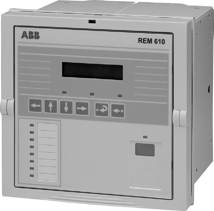
9 1MRS MUM 3. Instructions 3.1. HMI features Front panel The front panel of the protection relay includes: an alphanumeric 2 x 16 characters LCD with backlight and automatic contrast control three indicator LEDs (green, yellow, red) 8 programmable indicator LEDs (red) an HMI push-button section with four arrow buttons and buttons for clear/cancel and enter an optically isolated serial communication port with an indicator LED Display FrViewREM610_b Fig Front view of 1. LCD 2. HMI push-button section 3. Programmable indicator LEDs (red) 4. Indicator LEDs: Left: Ready (green) Centre: Start/Alarm (yellow) Right: Trip (red) 5. Indicator LED for front communication 6. Front communication port (infrared) Display test at power up When connecting the auxiliary voltage to the relay: 1. The backlight will be turned on after the relay has performed the internal power-up tests and entered into the protection mode. 2. The display will be tested by inverting it for approximately three seconds, see Fig In case a restart inhibit indication is displayed, the display test will not be run at power up. 9
10 1MRS MUM 3. The display will be returned to the idle mode and the backlight turned off if no operation indication message is displayed. However, if the non-volatile function is active, a message shown on the display before the auxiliary voltage was disconnected will reappear on the display. PowerUp_a Display modes Fig Display test at power up, display inverted When the display is in the idle mode, the name of the motor drive will be displayed, which by default is - ABB -. To change the name of the motor drive, use SPA parameter M20. - ABB - IdleMode_a Fig Display in the idle mode When the display is in the view mode, you can only view the settings. *GRP1 : 3.50 ViewMode_b Fig Display in the view mode When the display is in the setting mode, you can also edit the settings. *GRP1 : SetMode_b Fig Display in the setting mode Display backlight Normally the backlight of the display is off. Turn the backlight on by pressing an arrow button on the HMI. If the HMI panel is not used for approximately five minutes, the backlight will be turned off automatically. Activating the power-saving built-in feature by pressing will turn the backlight off within 20 seconds How to adjust the display contrast The display contrast is dependent on the temperature. automatically adjusts the contrast for optimum readability. When the display is in the idle mode, you can also adjust the contrast manually. To increase the contrast, hold down and adjust the contrast using. To decrease the contrast, hold down and adjust the contrast using. 10
11 1MRS MUM Push and increase or decrease Contrast_a Fig Adjusting the display contrast After power start up of the relay, the factory default value of the display contrast will automatically be restored How to use the push-buttons The HMI includes push-buttons for navigating in the menu. Navigation push-buttons Left Up Down Right Enter Clear/ Cancel Navigation_a Fig Navigation buttons Use the navigation buttons to view, select and edit desired menu items. Press an arrow button to activate the main menu. To move between the menu levels and menu items, use the arrow buttons. To select the item to be edited or to store a new value, press. To increase or decrease the activated digit, shift the activated decimal point, or to navigate between options, use and. To cancel and return the display to the previous mode (view mode or idle mode), press. Table Button navigation and editing Desired step or operation Step downward in the main menu or a submenu Step upward in the main menu or a submenu Entering a submenu from the main menu or a higher submenu Leaving a submenu for the main menu or a higher submenu Increasing a value in the setting mode Decreasing a value in the setting mode Push-button Moving the cursor in the setting mode or Selecting the front connection at power up and Entering or leaving the setting mode, storing a new value Entering the monitoring state and Adjusting the display contrast and or Resetting or cancelling, leaving the setting mode without storing a new value 11
12 1MRS MUM Table Button navigation and editing Resetting latched output contacts in the idle mode for 5 s Acknowledging and resetting indications, latched output contacts and memorized values Resetting thermal level to 0 at power up and and Main menu The main menu contains five main groups: MEASUREMENTS RECORDED DATA INFO MEASUREMENTS 1stMainMenu_a Fig The display showing the first main menu group Submenu To navigate between the main menu groups, use and. To return the display to the idle mode, press. The display will be returned to the idle mode on expiration of the time out. The menu structure contains several subgroups. The name of the main menu group is always shown on the first line. The second line displays either the name of the group menu, the name of the parameter and the parameter value, or just the parameter value, in which case it is also the name of the parameter. MEASUREMENTS L1 In:x.xx 1stSubmenu_a Fig The display showing the first submenu To enter a submenu, press ; to exit, press. To navigate between the main levels in the submenus, use or. Press to return the display to the idle mode HMI password The HMI password protects all user-changeable values on the technical level from being changed by an unauthorized person. The password function will remain inactive until the default password has been replaced. The default HMI password is 999. You can also change the password from a remote unit via parameter V162, but you can only read the password via the HMI. 12
13 PasswordREM610_b 1MRS MUM As soon as you have replaced the default HMI password, the new password will be required for altering parameter values. Once you have given the valid password, the display will remain in the setting mode until returned to the idle mode. PASSWORD :000 Password_a Fig Password request for editing setting parameters Change the HMI password as follows: 1. Press an arrow button to access the main menu. 2. Use the arrow buttons to select \PASSWORD HMI and press. 3. Press to enter the setting mode and give the current HMI password if required. If the default password 999 is still valid, no password will be required. 4. The first digit of the password to be edited will start to flash. Set the digit using and. 5. Activate the next digit to be set by pressing or. 6. To store the new password and return the display to the view mode, press. The display will confirm the storage by once flashing --- on the display. Alternatively, to exit the setting mode without storing the password change, press once before confirming and the display will be returned to the view mode. 7. Press to return the display to the idle mode. Main Menu Group Menu Parameter Menu MEASUREMENTS RECORDED DATA INFO FUNCTION TEST/DI COMMUNICATION LANGUAGE MEMORY FREQUENCY PASSWORD HMI TIME TRIP CIRCUIT SUP RTD INPUTS PASSWORD HMI :xxx Scroll for the digit Set the digit Confirm Cancel Fig Changing the HMI password SPA password The password for SPA bus communication is required for altering parameter values via the SPA bus. The default password is 001. You can change the SPA password either via the HMI or the SPA bus by first entering the currently valid password into parameter V160 and then entering the new password into parameter V
14 SPApwREM610_b 1MRS MUM Change the SPA password as follows: 1. Press an arrow button to access the main menu. 2. Use the arrow buttons to select \COMMUNICATION\SPA \PASSWORD SPA and press. 3. Press to enter the setting mode and give the current HMI password if required. If the default HMI password 999 is still valid, no password will be required. 4. The first digit of the password to be edited will start to flash. Set the digit using and. 5. Activate the next digit to be set by pressing or. 6. To store the new SPA password and return the display to the view mode, press. The display will confirm the storage by once flashing --- on the display. Alternatively, to exit the setting mode without storing the SPA password change, press once before confirming and the display will be returned to the view mode. 7. Press to return the display to the idle mode. Main Menu Group Menu Parameter Menus MEASUREMENTS RECORDED DATA INFO FUNCTION TEST/DI COMMUNICATION LANGUAGE MEMORY FREQUENCY PASSWORD HMI TIME TRIP CIRCUIT SUP RTD INPUTS REAR CONNECTION REAR PROTOCOL REAR COM. MODULE SPA IEC103 MODBUS UNIT ADDRESS :xxx COUNTER :xxx LINE-IDLE STATE CONNECTION TYPE PASSWORD SPA :xxx Scroll for the digit Confirm Set the digit Cancel Fig Changing the SPA password How to select language allows you to choose among several different languages. The default language is English. For the selection of languages, see Fig Change the display language as follows: 1. Press an arrow button to access the main menu. 2. Use the arrow buttons to select \LANGUAGE and press to enter the currently valid language. 3. Press to enter the setting mode and give the password if required. The second line will start to flash indicating that you are allowed to set the language. 4. Use or to move the cursor to the desired language. 5. Press to confirm the selection. The selected language will be shown on the display. 6. Press to return the display to the idle mode. 14
15 1MRS MUM By pressing before confirming the selection, the former language will remain active and the display will be returned to the view mode. Pressing again will return the display to the idle mode. Main Menu Group Menu Parameter Menu MEASUREMENTS RECORDED DATA INFO FUNCTION TEST/DI COMMUNICATION LANGUAGE MEMORY FREQUENCY PASSWORD HMI TIME TRIP CIRCUIT SUP RTD INPUTS ENGLISH SVENSKA SUOMI Fig Selecting language Note! The list of languages in the language selection menu differs depending on the HMI language set number in the order number How to set the real-time clock The real-time clock used for time-stamped events is set via two different settings, one for Year-Month-Day and another for Hours-Minutes-Seconds. To change one or both settings: 1. Press an arrow button to access the main menu. 2. Use the arrow buttons to select \TIME and press. 3. Use or to select the parameter to be edited. 4. Press to enter the setting mode and give the password if required. If the default password 999 is still valid, no password will be required. 5. The first digit of the setting value of the parameter to be edited will start to flash. Use and to move the cursor and and to increase or decrease the value. The setting range (e.g. Year or Minutes) is shown on the right-hand side of the second line of the display. 6. To store a new value and return the display to the view mode, press. 7. To exit the setting mode without storing the changes, press once before confirming and the display will be returned to the view mode. 8. Press to return the display to the idle mode. Confirm Cancel LanguageREM610_b 15
16 1MRS MUM Main Menu Group Menu Parameter Menu MEASUREMENTS RECORDED DATA FUNCTION TEST/DI INFO COMMUNICATION LANGUAGE MEMORY FREQUENCY PASSWORD HMI TIME TRIP CIRCUIT SUP RTD INPUTS YY-MM-DD hh.mm;ss (00-23) (00-59) Confirm Cancel TimeREM610_b Fig Setting the real-time clock How to switch between front and rear connection There are two means of serial communication available for the relay: the front connection for SPA bus communication and the optional rear communication module for communication via the SPA bus, IEC or MODBUS (RTU or ASCII) protocol. If the relay is not provided with an optional rear communication module, or if the module has been disabled, the front connection is always active and switching between front and rear connection is not allowed. If the optional rear communication module has been installed and enabled, the default setting is rear connection. Switch between front and rear connection as follows: 1. Press an arrow button to access the main menu. 2. Use the arrow buttons to select \COMMUNICATION and press. The cursor will be at the setting currently in use (REAR CONNECTION or FRONT CONNECTION). 3. Press to enter the setting mode. The second line will start to flash. 4. Use or to select the desired setting. 5. Press to confirm the selection. 6. Press to return the display to the idle mode. When the front connection has been selected and there is no communication for approximately five minutes, the rear connection will automatically be activated. To keep the front connection continuously active, press and simultaneously when connecting the auxiliary voltage to the relay. Note! When rear connection has been selected, the selected rear protocol will automatically be activated. 16
17 FrontRearREM610_b 1MRS MUM Main Menu Group Menu Parameter Menu MEASUREMENTS RECORDED DATA Confirm INFO FUNCTION TEST/DI COMMUNICATION LANGUAGE MEMORY FREQUENCY PASSWORD HMI TIME TRIP CIRCUIT SUP RTD INPUTS REAR CONNECTION REAR PROTOCOL REAR COM. MODULE SPA IEC103 MODBUS UNIT ADDRESS :xxx COUNTER :xxx LINE-IDLE STATE CONNECTION TYPE REAR CONNECTION Cancel FRONT CONNECTION Fig Switching between front and rear connection Indicator LED for front communication Indicator off: Rear communication is currently selected Lit indicator: Front communication port is currently selected Blinking indicator: Front communication port is currently selected and the relay is communicating How to select the protocol for rear communication allows you to choose the communication protocol for rear connection. The selected protocol is stored in the non-volatile memory and will therefore be activated automatically after an interruption in the auxiliary voltage. Select the rear communication protocol as follows: 1. Press an arrow button to access the main menu. 2. Use the arrow buttons to select \COMMUNICATION\REAR PROTOCOL and press. The cursor will be at the setting currently in use (e.g. SPA). 3. Press to enter the setting mode. The second line will start to flash. 4. Use or to select the desired setting. 5. Press to confirm the selection. 6. Press to return the display to the idle mode. 17
18 ProtocolREM610_b 1MRS MUM Main Menu Group Menu Parameter Menu MEASUREMENTS RECORDED DATA INFO FUNCTION TEST/DI COMMUNICATION LANGUAGE MEMORY FREQUENCY PASSWORD HMI TIME TRIP CIRCUIT SUP RTD INPUTS REAR CONNECTION REAR PROTOCOL REAR COM. MODULE SPA IEC103 :xxx MODBUS UNIT ADDRESS :xxx COUNTER :xxx LINE-IDLE STATE CONNECTION TYPE SPA IEC MODBUS RTU MODBUS ASCII Confirm Cancel Fig Selecting the communication protocol for rear connection 3.2. HMI operation levels User level The HMI menu consists of a user level and a technical level. The user level is used for measuring and monitoring whereas the technical level is used for advanced protection relay setting and can be configured to demand a password. The password will be required after the default value 999 has been replaced Menu groups of the user level The user level contains three menu groups: MEASUREMENTS = monitored measured values RECORDED DATA = stored event values from the protection functions registered number of starts of protection functions continuously updated registers of actual values from protection functions INFO = information on the relay, such as device type and relay serial number You can monitor the data without a password How to monitor measured values You can monitor all measured values via MEASUREMENTS in the HMI menu. In addition, the measured current values on phases L1, L2 and L3 and the measured value of I 0 can also be monitored by activating the monitoring state. To access the measured values on phases L1, L2 and L3 and the measured value of I 0, I 2 and θ via the HMI menu: 1. Press an arrow button to access the main menu. 2. The cursor will be at the first menu item, MEASUREMENTS. Press to see the measured value on phase L1. 3. Use and to monitor the measured values on phases L1, L2 and L3, and the measured value of I 0, I 2 and θ. The phase currents and the value of I 2 are shown 18
19 MeasurementsREM610_a 1MRS MUM as multiples of the rated current, I n, which correspond to the full load current (FLC) of the motor. I 0 is shown as a percentage of the rated current of the current transformer (CT) while θ is shown as a percentage of the thermal trip level. Press once more to see the corresponding primary current value for L1, L2, L3 and I 0. If the conversion factors have not been set, dashes will be displayed instead. 4. Use the arrow buttons to monitor other measured values in the menus TEMPERATURE DATA, CALCULATED DATA, DEMAND VALUES and HISTORY DATA; see Fig Press to return the display to the idle mode. Main Menu Group Menu Parameter Menu MEASUREMENTS RECORDED DATA INFO MEASUREMENTS L1 In:x.xx L2 In:x.xx L3 In:x.xx I0 %:x.xx I2 In:x.xx %:xxx TEMPERATURE DATA CALCULATED DATA DEMAND VALUES HISTORY DATA MEASUREMENTS L1 A:x.xx L2 A:x.xx L3 A:x.xx I0 A:x.xx MEASUREMENTS RTD1 C:+xxx RTD2 C:+xxx RTD3 C:+xxx RTD4 C:+xxx RTD5 C:+xxx RTD6 C:+xxx Th1 kw:x.x Th2 kw:x.x Cancel MEASUREMENTS åts s:xxx Rest.inh min min:xxx MEASUREMENTS MEASUREMENTS I 1_min In:x.xx I 1_min A:x.xx I n_min In:x.xx I n_min A:x.xx Max I In:x.xx Max I A:x.xx MEASUREMENTS Max IL In:x.xx Min IL In:x.xx Max I0 %:x.xx Min I0 %:x.xx Running time :xxx MEASUREMENTS Max IL Min IL Max I0 Min I0 A:x.xx A:x.xx A:x.xx A:x.xx Fig Measurements To access the primary current values by activating the monitoring state: 1. Press and simultaneously to view the primary line currents on phases L1, L2 and L3 and the earth-fault current, I Press to return the display to the idle mode. The display has to be in the idle mode to be able to activate the monitoring state. The display will not be returned to the idle mode automatically as the monitoring state does not have a time out. In case a fault is detected, however, the fault indication will displace the monitoring state. 19
20 RecordedREM610_a MonitoringREM610_a 1MRS MUM - ABB - + L1 x.xx L3 x.xx L2 x.xx I0 x.xx Fig Activating the monitoring state Note! The prerequisite for monitoring correct primary current values is that parameters M80 and M83 have been correctly set via serial communication How to monitor recorded data The contents of the event register and the information on motor start ups are found under the main menu group RECORDED DATA. 1. Press an arrow button to access the main menu. 2. Use or to select RECORDED DATA in the main menu and press to enter the first event. 3. To navigate between the events, use and. 4. To enter or exit a submenu, use or. 5. To return the display to the idle mode, press. Main Menu Group Menu Parameter Menus MEASUREMENTS RECORDED DATA INFO RECORDED DATA 1. EVENT 2. EVENT 3. EVENT 4. EVENT 5. EVENT NUMBER OF STARTS MOTOR START-UP RECORDED DATA 1. hh.mm;ss.sss 1. YY-MM-DD 1. L1 In:x.xx 1. L2 In:x.xx 1. L3 In:x.xx 1. ts> %:xxx 1. t>> %:xxx 1. t< %:xxx 1. I0 %:x.xx 1. t0> %:xxx 1. I2 In:x.xx 1. t2> %:xxx 1. I 2 * t %:xxx 1. s %:xxx 1. t %:xxx 1. n_motst :xxx Cancel 1. RTD1 C+:xxx RECORDED DATA 1. RTD2 C+:xxx START Is> :x 1. RTD3 C+:xxx START I>> :x 1. RTD4 C+:xxx START I< :x START I0> :x 1. RTD5 C+:xxx 1. RTD6 C+:xxx START I2> :x 1. Th1 kw:x.x RECORDED DATA 1. Th2 kw:x.x Start time s:xxx 1. AthA %:xxx Max ILs In:x.xx 1. PthA %:xxx 1. AthB %:xxx 1. PthB %:xxx Fig Recorded data 20
21 1MRS MUM INFO The main menu group INFO contains information you may need when ordering repair service. 1. Press an arrow button to access the main menu. 2. Use the arrow buttons to select INFO and press to enter the first submenu, which shows the device type, relay serial number, test date, the CPU module as well as the optional RTD module. 3. For specific information on the CPU module, use to select CPU MODULE and press to view the CPU software number and revision. While in the CPU software number and revision view, press to view the CPU build number or to view the CPU serial number. 4. Use the arrow buttons to monitor the corresponding information on the optional RTD module. 5. To return the display to the idle mode, press. Main Menu Parameter Menus MEASUREMENTS RECORDED DATA INFO INFO xxxxxxxx YYYYMMDD CPU MODULE RTD MODULE INFO 1MRS B xxxxxxxx INFO xxx Cancel INFO 1MRS A xxxxxxxx INFO xxx InfoREM610_b Fig INFO Technical level Menu system of parameters Press an arrow button to activate the main menu. If the default password is in use, no password will be required to change the parameters. If the password protection is in use, *** will be shown on the display until you give the valid HMI password. The views are used for reading and setting parameters, which are divided into two main groups: 21
22 1MRS MUM How to change settings The actual settings consist of the settings of group 1 or group 2, depending on which group that has been selected to be active (indicated by an asterisk * ). The actual settings can be seen in the first parameter menu, e.g. \PROTECT. STAGES\ Is> In:x.xx. Submenu Parameter Menu Is> In:x.xx * GRP 1 :x.xx GRP 2 :x.xx Confirm Cancel Gr1Gr2REM610_b Fig Setting parameters in setting group 1 and setting group 2 By switching between setting groups 1 and 2, the user can activate a whole group of settings at the same time. Switch between the setting groups as follows: with the parameter GROUP 1/GROUP 2 under the main menu group. with a digital input signal, provided that SGB1...5/4 has been set to 1 in both setting groups (GRP1 and GRP2). with parameter V150 via the SPA bus. When a large number of settings are to be altered, e.g. during commissioning of the relay systems, use a PC equipped with the necessary software. If such is not available, or when only a few settings are to be altered: 1. Press an arrow button to access the main menu. 2. Use the arrow buttons to select the main menu group and the desired group menu (e.g. PROTECT. STAGES), and press. 3. Use or to select the parameter to be changed and press. 4. Use or to select setting group 1 or 2 (GRP1 or GRP2). The active setting group is indicated by an asterisk *. 5. Enter the setting mode by pressing and give the password if required. If the default password 999 is still valid, no password will be required. 6. The first digit of the setting value of the parameter to be edited will start to flash. Use and to move the cursor and and to increase or decrease the number. 7. To store a new value and return the display to the view mode, press. If the parameter is of a numerical kind, the display will confirm the storage by once flashing --- on the display. 8. To exit the setting mode without storing the changes, press once before confirming and the display will be returned to the view mode. 9. Press to return the display to the idle mode. 22
23 1MRS MUM Main Menu Group Menu Parameter Menus MEASUREMENTS RECORDED DATA INFO PROTECTED UNIT PROTECT. STAGES OPT. STAGES ThA OPT. STAGES ThB SGF SGB SGR SGL GROUP 1/GROUP 2 NEW TRIP IND. DEMAND PU-SCALE :x.xx Is> In:x.xx * GRP 1 :x.xx Edit/Confirm ts> s:x.xx GRP 2 :x.xx I>> In:x.xx Cancel t>> s:x.xx I< %: xx t< s:xxx I0> %: x.xx t0> s:x.xx I2> In:x.xx K2 :xxx a> %:xxx i> %:xxx t6x s:x.xx p %:xxx KC : xx Tamb C: xx åtsi s:xxx Dåts s/h:xxx CBFP s:x.xx * GRP 1 :x.xx GRP 2 :x.xx Ta1> C:xxx * GRP 1 :xxx ta1> s:xxx GRP 2 :xxx Tp1> C:xxx tp1> s:xxx Ta2> C:xxx ta2> s:xxx Tp2> C:xxx tp2> s:xxx Ta3> C:xxx ta3> s:xxx Tp3> C:xxx tp3> s:xxx Th1> kw:x.x * GRP 1 :x.x GRP 2 :x.x Ta4> C:xxx * GRP 1 :xxx ta4> s:xxx GRP 2 :xxx Tp4> C:xxx tp4> s:xxx Ta5> C:xxx ta5> s:xxx Tp5> C:xxx tp5> s:xxx Ta6> C:xxx ta6> s:xxx Tp6> C:xxx tp6> s:xxx Th2> kw:x.x * GRP 1 :x.x GRP 2 :x.x SETTING GROUP 1 DISABLED MIN :xxx DEMAND VALUE :xxx SETTING GROUP 1 SETTING GROUP 2 SettingsREM610_b Fig Settings Switchgroups The relay includes the following switchgroups: SGF1 SGF2 SGF3, SGF4 SGF5 SGB1...SGB5 SGR1...SGR5 SGL1...SGL8 Output contacts Display settings Protection functions Latching feature for programmable LEDs Digital inputs (DI1...DI5) Output contacts (PO1, PO2, PO3, SO1, SO2) Programmable LEDs 23
24 SettingBits_a SettingsSG_REM610_a 1MRS MUM To set functions via switchgroups: 1. Press an arrow button to access the main menu. 2. Use the arrow buttons to select the main menu group and the desired switchgroup menu (e.g. SGF), and press. 3. Use or to select the desired switchgroup (e.g. SGF2 for display settings) and press. 4. Use or to select setting group 1 or 2 (GRP1 or GRP2). The active setting group is indicated by an asterisk *. 5. Press to enter the setting mode and give the password if required. 6. Use or to select the bit to be set, and or to select the desired bit state, see Fig Press to confirm the selection. After confirmation, the display will return to the view mode and show the checksum of the switchgroup. 8. Press to return the display to the idle mode. Main Menu Group Menu Parameter Menus MEASUREMENTS RECORDED DATA Edit/Confirm INFO PROTECTED UNIT PROTECT. STAGES OPT. STAGES ThA OPT. STAGES ThB SGF SGB SGR SGL GROUP 1/GROUP 2 NEW TRIP IND. DEMAND SGF1 SGF2 SGF3 SGB1 SGR1 SGF4 :x SGF5 :xxx SGB2 SGB3 SGB4 SGB5 SGR2 SGR3 SGR4 SGR5 SGL1 SGL5 :xxxxxxxx :xxxxxxxx :xxxxxxxx :xxxxxxxx :xxxxxxxx SGL2 :xxxxxxxx SGL3 :xxxxxxxx SGL4 :xxxxxxxx SGL6 SGL7 SGL8 :xxx :xxxxxxxx :xxx :xxx :xxxx :xxxx :xxxx :xxxx :xxxx :xxxxxxxx :xxxxxxxx :xxxxxxxx :xxxxxxxx * GRP 1 :xxx GRP 2 :xxx * GRP 1 :xxxx GRP 2 :xxxx * GRP 1 :xxxxxxxx GRP 2 GRP 2 Cancel :xxxxxxxx * GRP 1 :xxxxxxxx :xxxxxxxx Fig Settings for switchgroups Parameter Menu * GRP 1 :xxx GRP 2 :xxx * GRP 1 :x x Confirm Fig Setting bits Cancel Set the bit state (0 or 1) Scroll for the desired bit 24
25 1MRS MUM Configuration In general, the parameters found under are set only once by the customer, i.e. prior to commissioning of the relay. To alter a parameter: 1. Press an arrow button to access the main menu. 2. Use the arrow buttons to select the main menu group and the desired group menu, and press. 3. Use or to select the desired parameter (e.g. UNIT ADDRESS :xxx) or set of parameters (e.g. SPA ). In case of a set of parameters, use arrow buttons until you reach the desired parameter. 4. Press to enter the setting mode and give the password if required. 5. The parameter text (enumerator) or the first digit of the parameter setting value will start to flash. Set the enumerator or the digit/character using and. Activate the next digit/character to be set by pressing or. When setting an enumerator, however, the left and right arrows have no function. 6. To store a new value and return the display to the view mode, press. If the parameter is of numerical kind, the display will confirm the storage by once flashing --- on the display. 7. To exit the setting mode without storing the changes, press once before confirming and the display will be returned to the view mode. 8. Press once more to return the display to the idle mode. Note! If a setting value beyond the allowed limits is confirmed in the setting mode, the former value will be restored. 25
26 Config1REM610_b 1MRS MUM Main Menu Group Menu Parameter Menus MEASUREMENTS RECORDED DATA INFO FUNCTION TEST/DI COMMUNICATION LANGUAGE MEMORY FREQUENCY PASSWORD HMI TIME TRIP CIRCUIT SUP RTD INPUTS FUNC.TEST :x DI STATUS LED TEST REAR CONNECTION REAR PROTOCOL REAR COM. MODULE SPA IEC103 MODBUS UNIT ADDRESS :xxx COUNTER :xxx LINE-IDLE STATE CONNECTION TYPE DI1 STATUS :x DI2 STATUS :x DI3 STATUS :x DI4 STATUS :x DI5 STATUS :x REAR CONNECTION FRONT CONNECTION SPA IEC MODBUS RTU MODBUS ASCII ENABLED DISABLED ENGLISH SVENSKA SUOMI DEUTSCH FRANCAIS ITALIANO ESPAÑOL MEM. :xxx PASSWORD SPA :xxx BAUD RATE :9.6 BAUD RATE :4.8 IEC103 SET :1 IEC103 SET :2 IEC103 SET :255 BAUD RATE :9.6 BAUD RATE :4.8 EVEN PARITY ODD PARITY NO PARITY CRC ORDER LOW/HIGH HIGH/LOW BAUD RATE :9.6 BAUD RATE :4.8 BAUD RATE :2.4 BAUD RATE :1.2 BAUD RATE :0.3 LIGHT-OFF LIGHT-ON LOOP STAR Fig Configuration, part 1 26
27 Config2REM610_b 1MRS MUM Main Menu Group Menu Parameter Menus MEASUREMENTS RECORDED DATA INFO FUNCTION TEST/DI COMMUNICATION LANGUAGE MEMORY FREQUENCY PASSWORD HMI TIME TRIP CIRCUIT SUP RTD INPUTS FREQUENCY :50 FREQUENCY :60 PASSWORD HMI :xxx YY-MM-DD hh.mm;ss TCS ENABLED TCS DISABLED CH 1 RTD/TH CH 2 RTD CH 3 RTD CH 4 RTD/TH CH 5 RTD CH 6 RTD NOT IN USE Pt Pt Pt Ni Ni Cu Ni120US PTC 0..20kW NOT IN USE Pt Pt Pt Ni Ni Cu Ni120US NOT IN USE Pt Pt Pt Ni Ni Cu Ni120US PTC 0..20kW NOT IN USE Pt Pt Pt Ni Ni Cu Ni120US Fig Configuration, part How to acknowledge and reset indications, output contacts and memorized values To clear the LEDs and the display, press. The LEDs and the display will be cleared only if the fault has disappeared. Press for at least five seconds to unlatch the output contacts. Note that the LEDs and the display have to be cleared before this. Press and simultaneously for at least half a second to perform a master reset, i.e. to clear indications and memorized values and to unlatch the output contacts. The display being inverted confirms this action. Memorized values include recorded data, disturbance recorder data and average values (demand values and history data, except for the running time). 27
28 1MRS MUM 3.3. Protection relay indications Indicator LEDs Green indicator LED The operation of the relay can be monitored by means of three different kinds of indications on the HMI: Three indicator LEDs with fixed functionality: Ready, Start/Alarm and Trip Eight programmable indicator LEDs A text message on the display The protection functions are not affected by fault indications. When a protection stage starts or generates an alarm, the yellow indicator LED will be lit. When a protection stage trips, the yellow indicator LED will remain lit and the red indicator LED will be lit. When a starting protection stage is blocked, the yellow indicator LED will start to blink. The yellow indicator LED will also be lit to indicate an alarm from a protection stage. Green_a Yellow indicator LED Fig Green indicator LED Two different functions are embedded in the green indicator LED: power on and internal relay fault (IRF). Indicator off: The auxiliary voltage is not connected. Lit indicator: The relay is in operation. However, a less severe fault (warning) may have occurred. Refer to section Indications for internal relay faults (IRFs) and warnings. Blinking indicator: An internal relay fault requiring repair by an authorized service supplier has occurred. Refer to section Indications for internal relay faults (IRFs) and warnings. Yellow_a Fig Yellow indicator LED Indicator off: No protection stage has started and there are no thermal alarms. 28
29 1MRS MUM Lit indicator: Red indicator LED A protection stage has started or generated an alarm. The start and alarm indication can be selected to be either latching or non-latching with the SGF switches. A non-latching indication will automatically be cleared when the fault has disappeared and the protection stage has been reset, whereas a latching indication will remain lit until manually cleared. Blinking indicator: Starting protection stages have been blocked by an external digital input signal. The blocking indication is non-latching, i.e. it will disappear with the digital input signal. The yellow indicator LED will continue blinking for as long as a protection stage remains blocked. The blocking indication will disappear with the digital input signal or when the protection stage is no longer starting. If a protection stage is blocked when other protection stages are starting, the indicator will continue blinking. This because a blocking indication has a higher priority than a starting indication. Red_a Fig Red indicator LED Indicator off: No protection stage has tripped. Lit indicator: A protection stage has tripped. The trip indication is latching, i.e. it will remain lit until manually cleared Programmable indicator LEDs In addition to the three fixed LEDs, the relay includes eight LEDs which you can program to indicate the status of different type of relay signals. The programmable LEDs can indicate the following information: Trip signals from protection stages Alarm signals from protection stages Motor status and restart inhibit status Status of the digital input signals Rout the signals to the LEDs via switchgroups SGL1...SGL8; to LED1 with the switches of switchgroup SGL1, to LED2 with those of SGL2, and so forth. Each SGL consists of 20 alternative signals. For detailed information on the signals, refer to the Technical Reference Manual. The LEDs are non-latching by default but you can also set them to operate as latching via switchgroup SGF5. 29
30 1MRS MUM Indication messages For instructions on setting the switchgroups, refer to section Switchgroups. The messages give an overview of protection operations and internal relay faults Operation indication messages When a protection stage starts, the text START will appear on the display along with the name of the function. Additionally, in case of a latching start indication, the name of the energizing input(s) which caused the fault will be displayed (except for the motor start-up supervision based on thermal stress calculation and the unbalance protection). The yellow indicator LED will be lit. I>> START L1 StartIEC_a Fig Latching start indication When a protection stage trips, the text TRIP will appear on the display along with the name of the function. Additionally, the name of the energizing input(s) which caused the fault will be displayed (except for the motor start-up supervision, phase unbalance, phase reversal, thermal overload and temperature protection). The red indicator will be lit. I>> TRIP L1/L2 TripIEC_a Fig Trip indication In case of an alarm from the thermal overload or temperature protection, the text ALARM will appear on the display along with the function symbol and the yellow indicator LED will be lit. > ALARM AlarmIEC_a Fig Alarm indication In case of a restart inhibit state, the text RESTART INHIBIT will appear on the display. The state will not affect the start/alarm and trip LEDs, but instead you can use a programmable LED to indicate the state; refer to section Programmable 30
31 1MRS MUM indicator LEDs. The text message for the restart inhibit state is non-latching, whereas the status indication via a programmable LED can be either latching or nonlatching. The restart of a motor can be inhibited by the thermal protection, the cumulative start-up time counter or an external digital input signal. For the priority of indications for the restart inhibit state; refer to section Priority of operation indication messages. RESTART INHIBIT S tsi RestInhIEC_a Fig Restart inhibit indication Latching and non-latching indications A latching operation indication message will remain on the display until manually cleared or until replaced by a message of higher priority. However, if the fault is stable and has not disappeared, the operation indication message and the LED(s) will not be cleared. An operation indication generated by a non-latching start will automatically be cleared when the stage is reset. Priority of operation indication messages The messages on the display have a certain priority order. If different types of indications are activated simultaneously, the message with the highest priority will appear on the display. The priority order of the messages: 1. CBFP 2. Trip 3. Start/Alarm 4. Restart inhibit 4.1. Thermal protection 4.2. Cumulative start-up time counter 4.3. External restart inhibit When several protection stages generate starts or alarms, the last start/alarm indication message will be displayed. When several protection stages trip, the first trip indication message will be displayed until the time, as specified by the NEW TRIP IND. setting value, has expired. After this, a new trip indication message can displace the old one. A hidden trip indication message can be brought forward by pressing Disturbance recorder indication When the display is in the idle mode, an asterisk * indicating that the disturbance recorder has been triggered and is ready to be unloaded, will be shown in the lower right-hand corner of the display. 31
32 1MRS MUM Indications for internal relay faults (IRFs) and warnings There are two types of fault indications; internal relay fault (IRF) indications and warnings. Internal relay faults prevent relay operation while less severe faults (called warnings) allow continued relay operation with full or reduced functionality. Internal relay fault (IRF) At permanent internal relay faults, the relay is no longer protecting and has to be sent for repair at an authorized service supplier. When the self-supervision system detects a permanent internal relay fault, the green indicator LED will start to blink and the text INTERNAL FAULT and a fault code will appear on the display. State the fault code when sending the relay for service. As long as the green indicator LED (ready) is blinking, the fault indication cannot be cleared. In case an internal fault disappears, the green indicator LED will stop blinking and the relay will be returned to the normal service state, but the fault indication message will remain on the display until manually cleared (or a motor start up begins). INTERNAL FAULT FAULT CODE :30 IntFault_a Fig Permanent IRF The fault code is of a numerical kind and identifies the fault type. The fault codes are listed in the table below: Table IRF codes Fault code Type of fault 4 Error in output relay PO1 5 Error in output relay PO2 6 Error in output relay PO3 7 Error in output relay SO1 8 Error in output relay SO2 9 Error in the enable signal for output relays PO1,PO2,SO1,SO2 10, 11, 12 Error in the feedback, enable signal or output relays PO1,PO2,SO1,SO2 20, 21 Auxiliary voltage dip 30 Faulty program memory 50, 59 Faulty work memory 51, 52, 53 2), 54, 56 Faulty parameter memory 1) 55 Faulty parameter memory, calibration parameters 75 RTD module faulty 80 RTD module missing 81 RTD module unknown 82 RTD module configuration error 85 Power supply module faulty 86 Power supply module unknown 90 Hardware configuration error 95 Communication module unknown 32
33 1MRS MUM Table IRF codes Fault code 104 Faulty configuration set for IEC , 139, 195, 203, Internal reference voltage error 222, Error in the measuring unit 1) May be corrected by formatting to the factory setting. 2) All setting values will be zero during the fault. Warning Type of fault In case of a less severe fault (warning), the relay will continue to operate except for those protection functions possibly affected by the fault. At this type of fault, the green indicator LED will remain lit, but the text WARNING with a fault code or a text message indicating the fault type will replace the name of the motor drive on the display in the idle mode. Some of these faults can be corrected by a relay operator at site. After the fault has disappeared or been corrected, the message will automatically be cleared. WARNING BATTERY LOW Warning_a Fig Warning with text message If more than one type of fault occur at the same time, one single numeric code which indicates all the faults will be displayed. For instance, 2049 implies two faults: the battery is low and the temperature sensor RTD6 is faulty. The code is composed of the weighting factors assigned to each fault type as follows: ; see Table WARNING FAULT CODE: 2049 Warning2_a Fig Warning with numeric code Table Warning codes Fault Weighting factor Description Battery low 1 Battery voltage level low - Battery should be replaced - Warning will not be displayed if non-volatile memory settings have been set to 0 - In case only this warning is active, it will be displayed in text format (BATTERY LOW) 33
34 1MRS MUM Table Trip-circuit supervision Power supply module temperature high Communication module faulty or missing RTD module faulty Temperature sensor range error Sensor circuit open or shorted (RTD1) Sensor circuit open or shorted (RTD2) Sensor circuit open or shorted (RTD3) Warning codes 2 Error in trip circuit - Check the trip circuit for broken conductors and correct. - Warning will not be displayed if trip-circuit supervision (TCS) has been disabled 4 Temperature inside relay is too high - Check that ambient temperature is within service temperature range 8 Communication module faulty or not installed - Check that plug-in unit is properly attached to relay case - Check that communication module is installed - Warning will not be displayed if rear communication module has been disabled - In case only this warning is active, it will be displayed in text format (Comm.card faulty) 16 Three possible causes: 1) Storing in non-volatile memory has not been successful, which means that old settings will be taken into use after power up 2) Self calibration has failed 3) Offset voltage out of range - If warning is not cleared after a power reset, the relay may require service 32 At least one sensor (RTD1...6) is outside measurement range - Check that sensors are not broken 64 Circuit is open or shorted 1) - Check wiring of sensor - Check that sensor is not broken 128 Circuit is open or shorted 1) - Check wiring of sensor - Check that sensor is not broken 256 Circuit is open or shorted 1) - Check wiring of sensor - Check that sensor is not broken Sensor circuit open or shorted (RTD4) 512 Circuit is open or shorted 1) - Check wiring of sensor - Check that sensor is not broken Sensor circuit open or shorted (RTD5) 1024 Circuit is open or shorted 1) - Check wiring of sensor - Check that sensor is not broken Sensor circuit open or shorted (RTD6) 2048 Circuit is open or shorted 1) - Check wiring of sensor - Check that sensor is not broken Thermistor circuit open or shorted (Thermistor1) Thermistor circuit open or shorted (Thermistor2) Σ: Circuit is open or shorted - Check wiring of thermistor - Check that thermistor is not broken 8192 Circuit is open or shorted - Check wiring of thermistor - Check that thermistor is not broken 1) Temperature protection stages are out of operation. 34
Overcurrent and Earth-Fault Relay REJ 525. Technical Reference Manual
 Overcurrent and Earth-Fault Relay MRS75094-MUM Issued: 4.09.998 Version: D/4..2005 Overcurrent and Earth-Fault Relay Contents. About this manual...5.. Copyrights...5.2. Trademarks...5.3. Guarantee...5.4.
REX 521 Protection Relay Operator s Manual
 REX 521 Industrial IT enabled products from ABB are the building blocks for greater productivity, featuring all the tools necessary for lifecycle product support in consistent electronic form. 1MRS 751107-MUM
Protection Relay RE_ 610. Installation Manual
 RE_ 0 MRS-MUM Issued:..00 Version: E/0..00 RE_ 0 Contents Copyrights.... Introduction........ This manual........ Use of symbols........... Intended audience........ Product documentation........... Document
Combined Overcurrent and Earth-fault Relay SPAJ 140 C. Product Guide
 Combined Overcurrent and Earth-fault Product Guide Issued: April 1999 Status: Updated Version: C/18.04.2006 Data subject to change without notice Features Three-phase, low-set phase overcurrent unit with
Combined Overcurrent and Earth-fault Relay SPAJ 141 C. Product Guide
 Combined Overcurrent and Earth-fault Product Guide Issued: April 1999 Status: Updated Version: C/19.04.2006 Data subject to change without notice Features Three-phase, low-set phase overcurrent unit with
General characteristics of C-type relay modules
 General characteristics of C-type relay modules User s manual and Technical description B I > I >> Indicators for measured values I L1 I L2 I L3 IRF Self-supervision alarm indicator (Internal Relay Fault)
Residual overvoltage relay
 Page 1 Issued: April 1999 Status: New Data subject to change without notice Features Definite-time residual overvoltage earthfault protection and supervision Two independent operation stages, e.g. one
2 Table of Contents 1. TABLE OF CONTENTS. 1. Table of Contents Introduction Wiring Diagram Terminals Review...
 TPR-6 Temperature Protection Relay Instruction Manual Ver. June 1 st 2010 2 Table of Contents 1. TABLE OF CONTENTS 1. Table of Contents... 2 2. Introduction... 3 3. Wiring Diagram... 5 4. Terminals Review...
Voltage regulator. SPAU 341 C 1MRS MBG Issued: July 1998 Status: Revised Version: C/ Data subject to change without notice
 Issued: July 1998 Status: Revised Version: C/08.10.2003 Data subject to change without notice Features Comprehensive voltage regulation for power transformers with on-load tapchangers in distribution substations
Directional or Non-Directional Earth-Fault Relay REJ 527. Product Guide
 Directional or Non-Directional Earth-Fault Product Guide Issued: 17.06.19994 Status: Updated Version: C/16.10.2002 Data subject to change without notice Features Directional or non-directional low-set
Sensitive definite time or inverse time earth-fault stage for back-up residual earthfault
 Issued: April 1999 Status: Updated Version: B/09.11.2001 Data subject to change without notice Features Sensitive restricted earth-fault protection stage for fast, selective earth-fault protection Sensitive
Earth-fault Relay SPAJ 110 C. Product Guide
 Issued: April 1999 Status: Updated Version: C/12.04.2006 Data subject to change without notice Features Low-set neutral overcurrent stage with definite time or inverse time characteristic High-set neutral
VAMP 221. Table of Contents
 2 V221/EN M/E019 VAMP 221 Table of Contents Table of Contents 1. General... 7 1.1. VAMP 221 arc protection system components... 7 1.1.1. Central unit VAMP 221... 9 1.1.2. I/O units VAM 12L / VAM 12 LD,
Sensitive Earth-fault Relay SPAJ 111 C. Product Guide
 Issued: April 1999 Status: Update Version: C/12.04.2006 Data subject to change without notice Features Sensitive low-set neutral overcurrent stage with definite time characteristic High-set neutral overcurrent
Motor Protection Relay REM 610. Product Guide
 Product Guide Contents 1 Description.............................. 3 2 Protection functions....................... 3 3 Measurement............................ 4 4 Disturbance recorder......................
Instructions. Modbus RTU Card (WSIQ-COM-MB)
") Instructions (WSIQ-COM-MB) Contents 1 Warnings... 2 2 Important User Information... 2 3 Installation... 2 4 Operation... 3 5... 4 6 Specifications... 15 Product Compatibility The is suitable for use with
Instructions (WSIQ-COM-MB) Contents 1 Warnings... 2 2 Important User Information... 2 3 Installation... 2 4 Operation... 3 5... 4 6 Specifications... 15 Product Compatibility The is suitable for use with
Feeder protection relay SPAA 121 C. Product Guide
 Issued: April 1999 Status: Updated Version: C/06.03.2006 Data subject to change without notice Features Two-phase low-set phase overcurrent unit with definite time or inverse time characteristic Two-phase
RER 123 Bus Connection Module. Technical Description
 Bus Connection 1MRS751143-MUM Issued: 06.11.1998 Version: E/08.07.2005 Bus Connection 1. About this manual...4 1.1. Copyrights...4 1.2. Trademarks...4 1.3. Guarantee...4 2. Safety information...5 3. General...6
FREQUENCY CONVERTER FC102 (QUICK GUIDE)
") FREQUENCY CONVERTER FC102 (QUICK GUIDE) INSTALLATION AND MAINTENANCE Content Page Safety instructions 2 IT system 3x230VAC 2 Connections 3 Control unit (LCP) 4 Manual operation 4 Reverse the direction
FREQUENCY CONVERTER FC102 (QUICK GUIDE) INSTALLATION AND MAINTENANCE Content Page Safety instructions 2 IT system 3x230VAC 2 Connections 3 Control unit (LCP) 4 Manual operation 4 Reverse the direction
Multifunction Protection and Switchgear Control Unit. Operator's manual
 REF 542plus 1MRS755869 Issued: 01.11.2002 Version: C/31.05.2007 REF 542plus Contents Copyrights... 7 1. Introduction...9 1.1. This manual... 9 1.2. Use of symbols... 9 1.3. Intended audience... 9 1.4.
Iso DIN. User Manual. 1 channel Earth Fault Monitoring
 Page 1 of 5 2017 03 20 User Manual Iso DIN Iso DIN User Manual 1 channel Earth Fault Monitoring Megacon AB Ranhammarsvägen 20 S 168 67 Bromma Sweden Tel: 08 402 42 50 sales@megacon.se www.megacon.se eee
SPA-ZC 200/SPA-ZC 202 IEC /SPA-gateway Modules. Installation Manual
 Issued: 29.03.2001 Version: A/29.03.2001 Checked: M.K. Approved: We reserve the right to change data without prior notice. Contents: 1. Safety information...4 2. Introduction...5 2.1. Contents of delivery...5
DGSZV-EP DIGITAL GALVANIC LONGITUDINAL DIFFERENTIAL PROTECTION. Application field
 DGSZV-EP DIGITAL GALVANIC LONGITUDINAL DIFFERENTIAL PROTECTION The digital galvanic longitudinal differential protection of type DGSZV-EP is part of device family named EuroProt. This short description
REF 54_ Feeder Terminal REM 54_ Machine Terminal Operator s Manual
 REF 54_ Feeder Terminal REM 54_ Machine Terminal Industrial IT enabled products from ABB are the building blocks for greater productivity, featuring all the tools necessary for lifecycle product support
Synchro-check relay. Application
 Issued: April 1999 Status: Updated Version: B/08.11.2001 Data subject to change without notice Features Two identical operation stages allowing the closing conditions of two separate circuit breakers to
FREQUENCY CONVERTER FC101 (QUICK GUIDE)
") FREQUENCY CONVERTER FC101 (QUICK GUIDE) INSTALLATION AND MAINTENANCE Content Page Safety instructions 2 IT system 3x230VAC 2 Connections 3 Control unit (LCP) 4 Manual operation 4 Reverse the direction
FREQUENCY CONVERTER FC101 (QUICK GUIDE) INSTALLATION AND MAINTENANCE Content Page Safety instructions 2 IT system 3x230VAC 2 Connections 3 Control unit (LCP) 4 Manual operation 4 Reverse the direction
MiCOM P122C Time-Overcurrent Protection
 Protection Relays 01 MiCOM P122C Time-Overcurrent Protection Customer Benefits 1A/5A software setting 4 function keys Compact unit for flush and wall-surface mounting Comprehensive measurements Disturbance
It is the installer's responsibility to follow all instructions in this manual and to follow correct electrical practice.
 MCD Modbus Module Instructions Important User Information INSTALLATION INSTRUCTIONS: MCD MODBUS MODULE Order Code: 175G9000 1. Important User Information Observe all necessary safety precautions when controlling
Feeder protection relay
 Page 1 Issued: April 1999 Status: New Data subject to change without notice Features Comprehensive numerical feeder protection relay consisting of two multi-function protection relay modules and a flexible
Compressor Controller MAM 890
 Compressor Controller MAM 890 OPERATION MANUAL Revision 1.0 04.08.2017 Notice Please read all the operation manual before operating the set and keep this manual for further reference. Installation of MAM
Dryer. M720 Programming and Operation Manual. July 15, 2015 Revision 1.51
 Dryer M720 Programming and Operation Manual July 15, 2015 Revision 1.51 Contents 1 Important Safety Information 1 1.1 FOR YOUR SAFETY - CAUTION!............................. 1 2 Control Overview 2 2.1
HGM9580 Bus Tie Bus Parallel Unit USER MANUAL. Smartgen Technology
 HGM9580 Bus Tie Bus Parallel Unit USER MANUAL Smartgen Technology This manual is suitable for HGM9580 bus tie bus parallel unit only. Clarification of notation used within this publication. SIGN INSTRUCTION
MODBUS RTU MODULE INSTRUCTIONS. for use with WSIQ2/WSE
 INSTRUCTIONS MODBUS RTU MODULE for use with WSIQ2/WSE WorldWide Electric Corporation Phone: 1-8-88-2131 Fax: 1-8-711-1616 www.worldwideelectric.net Product Compatibility This communications module is suitable
GRUNDFOS INSTRUCTIONS. Control MPC. Installation and operating instructions
 GRUNDFOS INSTRUCTIONS Control MPC Installation and operating instructions English (GB) English (GB) Installation and operating instructions Original installation and operating instructions CONTENTS Page
1. Introduction. 2. Installation MODBUS INTERFACE
 5551.C 8473.C MODBUS INTERFACE PIM-MB-1 Modbus Interface 1. Introduction AuCom soft starters can be controlled and monitored across an RS485 serial communication network using the Modbus RTU and AP ASCII
7SR21 Non-Directional 7SR22 Directional Overcurrent Relay
 7SR21 Non-Directional 7SR22 Directional Overcurrent Relay Document Release History This document is issue 2010/05. The list of revisions up to and including this issue is: 2010/05 Additional Comms module
User Manual. AQ-F215 Simulator
 User Manual AQ-F215 Simulator Instruction manual AQ-F215 Simulator 2 (28) Revision 1.00 Date 16.5.2014 Changes N/A Revision 1.01 Date 13.3.2018 Changes Updated visual look Readability improvements Instruction
Protection and Control Terminals RE_ 54_. Operator s Manual
 Protection and Control Terminals RE_ 54_ 1MRS750500-MUM Issued: 23.09.1997 Version: N/08.07.2005 Protection and Control Terminals RE_ 54_ 1. About this manual...5 1.1. Copyrights...5 1.2. Trademarks...5
Supplementary operating instructions for your air curtain system Controller TMC 500
 Supplementary operating instructions for your air curtain system Controller TMC 500 (Translation of the original) Serial number: Year: Please quote this number when contacting customer service! Date 08.04.2016
Feeder protection relay SPAA 341 C. Product Guide
 Issued: April 1999 Status: Updated Version: D/07.03.2006 Data subject to change without notice Features Comprehensive numerical feeder protection relay consisting of two multi-function protection relay
ABB Drives. User s Manual. Modbus Adapter Module RMBA-01
 ABB Drives User s Manual Modbus Adapter Module RMBA-01 Modbus Adapter Module RMBA-01 User s Manual 3AFE 64498851 REV A EN EFFECTIVE: 1.3.2002 2002 ABB Oy. All Rights Reserved. Safety instructions Overview
Overview This section describes how to use the LTM R controller via the network port using the Modbus protocol.
 7.6 Using the Modbus Communication Network Overview This section describes how to use the LTM R controller via the network port using the Modbus protocol. LOSS OF CONTROL WARNING The designer of any control
M2500 Engine Controller Configuration Manual
 M2500 Engine Controller Configuration Manual Revision: 08-04-2011 Page 1 Contents 1 Preface... 4 2 Configuration from front panel... 5 2.1 Engine Controller Configuration... 6 2.1.1 RPM settings... 6 2.1.2
Copyright: December 2017 Nidec Issue: E
 General Information The manufacturer accepts no liability for any consequences resulting from inappropriate, negligent or incorrect installation or adjustment of the optional parameters of the equipment
Feeder Protection Relay REF 610. Product Guide
 Product Guide Contents 1 Description.............................. 3 2 Protection functions....................... 3 3 Measurement............................ 4 4 Disturbance recorder......................
TeSys U Communication Variables
 1744082 03/2009 TeSys U Communication Variables User s Manual 03/2009 1744082 www.schneider-electric.com Schneider Electric assumes no responsibility for any errors that may appear in this document. If
ATS Automatic transfer switches Advanced version
 87045 LIMOGES Cedex Phone :+33 05 55 06 87 87 Fax :+33 05 55 06 88 88 ATS CONTENTS PAGES 1. USE 1 2. RANGE 1 3. DIMENSIONS 1 4. ELECTRICAL AND MECHANICAL CHARACTERISTICS 2 5. CONFORMITY 4 6. EQUIPMENTS
Dual channel temperature logger with two binary inputs and LCD display Instruction Manual
 LOGGER S0841 Dual channel temperature logger with two binary inputs and LCD display Instruction Manual Instruction Manual for use of S0841 logger Instrument is designed for measurement and record of temperature
INTRODUCTION. The PL-50 MO and PM-250 families represent the. PM-250-H: Horizontal box. PM-250-V: Vertical box
 INTRODUCTION The PL-50 MO units are available in the next mechanical version: The PL-50 MO and PM-250 families represent the different solutions that Team Arteche offers for motor protection. Both families
Connectivity Packages. User's Guide - ANSI Version
 Connectivity Packages 1MRS756194 Issued: 30.11.2006 Version: A/30.11.2006 Connectivity Packages Contents Copyrights... 5 1. Introduction...... 7 1.1. Intended audience...... 7 1.2. Related documents.........
PowerView. Model PV-101 User s Guide. Rev Catalog Section 78
 PowerView Model PV-101 User s Guide Rev 09-10-08 00-02-0605 Catalog Section 78 In order to consistently bring you the highest quality, full featured products, we reserve the right to change our specifications
Dual channel temperature logger with display Instruction Manual
 LOGGER S0122 Dual channel temperature logger with display Instruction Manual ie-log-s0122-05 Instruction manual for use of temperature logger S0122 Logger is designed for measurement and record of ambient
Monitoring Technique. VARIMETER PRO Multifunction Measuring Relay MK 9300N, MH 9300
 Monitoring Technique VARIMETER PRO Multifunction Measuring Relay MK 93N, MH 93 268581 Product description MK 93N MH 93 The universal measuring relays MK 93N / MH 93 of the VARIMETER PRO series monitor
Arc protection relay. Features Three-phase overcurrent function. Application
 Arc protection relay REA 10_ Page 1 Issued: May 1999 Status: New Data subject to change without notice Features Three-phase overcurrent function Loop-type or radial sensor fibre for arc detection Two high-speed
MCD 200 MCD 500. Remove the Profibus Module using the following procedure: 1. Remove power from the module.
 Installation INSTALLATION INSTRUCTIONS: MCD PROFIBUS MODULE Order Code: 175G9001 1. Installation 1. Remove control power and mains supply from the soft starter. 2. Attach the module to the soft starter
Softstarters. Type PSTX Fieldbus communication, Fieldbus Plug Modbus RTU
 Softstarters Type PSTX Fieldbus communication, Fieldbus Plug Modbus RTU 1SFC132092M0201 July 2014 1 Modbus RTU The Modbus protocol is a fieldbus protocol that provides full control and status information
PowerView. Model PV-101-C User s Guide Version Catalog Section 78
 PowerView Model PV-101-C User s Guide Version 3.1 10-11-10 00-02-0718 Catalog Section 78 Table of Contents Introduction... 1 Engine and Transmission Parameters 2 Faceplate Features 3 Navigation and Keypad
EQ5 SERIES Quick Start Guide for Constant Torque Applications
 EQ5 SERIES Quick Start Guide for Constant Torque Applications PN EQ5QSCT, Revision: 0.02, April 4 th 2009 EQ5 Drive Quick Start Guide for Constant Torque Applications Contents Page Introduction... 3 1.
Observe all necessary safety precautions when controlling the soft starter remotely. Alert personnel that machinery may start without warning.
 MCD Profibus Module Instructions Important User Information Installation Instruction: MCD Profibus Module Order Code: 175G9001 1. Important User Information Observe all necessary safety precautions when
PowerView. Model PV-101-A, V2.3 User s Guide Section 78
 PowerView Model PV-101-A, V2.3 User s Guide 10-18-11 00-02-0795 Section 78 In order to consistently bring you the highest quality, full featured products, we reserve the right to change our specifications
How to control and monitor up to 16 Motor Insight motor protection relays via an HMi and Modbus serial
 Application The purpose of this application example is to demonstrate how to use the HMi electronic operator interface family to control and monitor up to 16 Motor InsightT motor protection relays via
OPERATOR'S MANUAL Generator Paralleling Controller, GPC-3 - Generator Protection Unit, GPU-3/GPU-3 Hydro - Paralleling and Protection Unit, PPU-3
 OPERATOR'S MANUAL Generator Paralleling Controller, GPC-3 - Generator Protection Unit, GPU-3/GPU-3 Hydro - Paralleling and Protection Unit, PPU-3 Display and push-button functions Alarm handling Log list
Data communication and reporting unit
 FAULT SRIO 1000M Data communication and reporting unit User s manual and Technical description SRIO 1000M ON 1 2 SERIAL IF 4 LOCAL 1 2 3 4 5 6 7 8 1 0 0543A 1MRS 750533-MUM EN Issued 1996-10-23 Modified
vacon nx ac drives brake chopper unit (bcu) application user s manual
 application user s manual") vacon nx ac drives brake chopper unit (bcu) application user s manual 2 vacon Introduction Vacon Brake Chopper Unit application INDEX Document code: DPD01565A Software code: ABFIFF01V113 Date: 27.3.2014
vacon nx ac drives brake chopper unit (bcu) application user s manual 2 vacon Introduction Vacon Brake Chopper Unit application INDEX Document code: DPD01565A Software code: ABFIFF01V113 Date: 27.3.2014
4511 MODBUS RTU. Configuration Manual. Universal trip amplifier. No. 4131MCM100(1402)
") 4511 MODBUS RTU Configuration Manual 4131 Universal trip amplifier 4131MCM100(1402) 4131 CONTENTS Introduction... 3 Modbus basics... 3 Modbus RTU... 3 Supported Function Codes... 3 Modbus Parameters and
4511 MODBUS RTU Configuration Manual 4131 Universal trip amplifier 4131MCM100(1402) 4131 CONTENTS Introduction... 3 Modbus basics... 3 Modbus RTU... 3 Supported Function Codes... 3 Modbus Parameters and
M550 & M560 MOTOR PROTECTION RELAY
 M550 & M560 MOTOR PROTECTION RELAY Figure 1 M550 Motor protection relay TECHNICAL REFERENCE GUIDE VOLUME 3.7 DocNo: M550 Manual v3.7 Contents 1. Introduction 5 About this manual 5 About the M550 5 About
Intech Micro 2300-A8VI analogue input station MODBUS RTU slave application supplementary manual.
 Intech Micro 2300-A8VI analogue input station MODBUS RTU slave application supplementary manual. MODBUS supplementary manual to the 2300-A8VI Installation Guide. The 2300 series stations are designed to
MiCOM P521. Fast feeder differential protection
 01 Fast feeder differential protection The relay provides high-speed two-ended current differential unit protection of overhead lines and underground cables in applications such as ring mains and parallel
2 Product Overview. 5 User Interface. 14 Logging Data. 17 Viewing Data. 19 Managing Data. 24 Device Settings. 26 Specifications.
 TITAN S8 Portable Data Acquisition Logger PRODUCT USER GUIDE To view the full MadgeTech product line, visit our website at madgetech.com. TABLE OF CONTENTS 2 Product Overview 5 User Interface 14 Logging
It is the installer's responsibility to follow all instructions in this manual and to follow correct electrical practice.
 Important User Information User Manual: MCD Profibus Module Order Code: 175G9001 1. Important User Information Observe all necessary safety precautions when controlling the soft starter remotely. Alert
Dual channel temperature logger with two voltage inputs 0-5V Instruction Manual
 LOGGER S0541 Dual channel temperature logger with two voltage inputs 0-5V Instruction Manual Instruction Manual for use of S0541 logger Instrument is designed for measurement and record of temperature
TITAN S8. Portable Data Acquisition Logger. Product User Guide
 TITAN S8 Portable Data Acquisition Logger Product User Guide Table of Contents 2 General Features... 3 Device Overview... 3 External Features... 3 Device Orientation... 4 Device Inputs... 5 Sensor Types
FLÄKTGROUP OFFERS A WIDE RANGE OF PER- MANENT MAGNET MOTORS (PM) AND FREQUENCY CONVERTERS FOR PLUG FANS. POWER RANGE IS FROM 0,8 KW TO 15 KW.
 AND FREQUENCY CONVERTERS FOR PLUG FANS. POWER RANGE IS FROM 0,8 KW TO 15 KW.") CENTRIFLOW PUR 3D (A, PLUG B, C, D) FAN GMPM FC101 AND SLIDE IN FREQUENCY ROTOR CASSETTE CONVERTER QUICK GUIDE FLÄKTGROUP OFFERS A WIDE RANGE OF PER- MANENT MAGNET MOTORS (PM) AND FREQUENCY CONVERTERS
CENTRIFLOW PUR 3D (A, PLUG B, C, D) FAN GMPM FC101 AND SLIDE IN FREQUENCY ROTOR CASSETTE CONVERTER QUICK GUIDE FLÄKTGROUP OFFERS A WIDE RANGE OF PER- MANENT MAGNET MOTORS (PM) AND FREQUENCY CONVERTERS
Temperature logger with display Instruction Manual
 LOGGER S0110 Temperature logger with display Instruction Manual Instruction manual for use of temperature logger S0110 Logger is designed for measurement and record of temperature from built-in internal
Protection relays.
 Protection relays www.vamp.fi Vamp Ltd Vamp Ltd, with a strong experience of designing devices, is an independent supplier of relays and monitoring equipment. The company has an established reputation
MiCOM P521. Fast Feeder Differential Protection
 01 Fast Feeder Differential Protection The relay provides high-speed two-ended current differential unit protection of overhead lines and underground cables in applications such as ring mains and parallel
User's guide SDMO Control unit KERYS TACTIL - S 9000 V 1.05 (29/06/06) _2_1
 _2_1") User's guide SDMO Control unit KERYS TACTIL - S 9000 V 1.05 (29/06/06) 33502015901_2_1 1. MICS Kerys... 2 1.1. Aim and structure... 2 2. Using the interface... 2 2.1. Presentation of the keypad... 2 2.1.1
User's guide SDMO Control unit KERYS TACTIL - S 9000 V 1.05 (29/06/06) 33502015901_2_1 1. MICS Kerys... 2 1.1. Aim and structure... 2 2. Using the interface... 2 2.1. Presentation of the keypad... 2 2.1.1
MiCOM P111. Three phase and earth fault overcurrent relays
 Three phase and earth fault overcurrent relays The relays are suitable for all the application where overcurrent and/or earth-fault protection are required. Thanks to its favorable price vs technical features
- 15G0078B110 - PROFIBUS MODULE INSTRUCTIONS FOR ASAC-0/ASAC-1/ASAB
 - 5G0078B0 - PROFIBUS MODULE INSTRUCTIONS FOR ASAC-0/ASAC-/ASAB Issued on 5/06/2 R. 0 This manual is integrant and essential to the product. Carefully read the instructions contained herein as they provide
RTD-500 Precision RTD Simulator. Operations Manual.
 RTD-500 Precision RTD Simulator Operations Manual. Page 1 of 16 Table of Content. Table of Content....1 1 Scope...3 2 Package Content....3 3 Technical Data....3 4 Preparation for use....4 4.1 Switching
User Guide Automatic Transfer Switch (ATS)
") User Guide Automatic Transfer Switch (ATS) V.1.0 Table of Contents 1. Introduction... 2 2. Product Overview... 2 3. Important Safety Warnings... 3 4. Operation Indicators & Status... 3 5. Installation...
User Guide Automatic Transfer Switch (ATS) V.1.0 Table of Contents 1. Introduction... 2 2. Product Overview... 2 3. Important Safety Warnings... 3 4. Operation Indicators & Status... 3 5. Installation...
BA688CF-F FOUNDATION fieldbus Panel mounting Display
 BA688CF-F FOUNDATION fieldbus Panel mounting Display Issue: 9 Issue: 9 6th June 2011 2 CONTENTS 1. Description 1.1 Documentation 1.2 Version 2.3 firmware 2. Operation 2.1 Controls 3. System Design 3.1
Softstarters. Type PSTX Fieldbus communication, Anybus Modbus TCP. 1SFC132087M0201 March SFC132087M0201 1
 Softstarters Type PSTX Fieldbus communication, Anybus Modbus TCP 1SFC132087M0201 March 2015 1SFC132087M0201 1 1 Modbus TCP The Modbus protocol is a fieldbus protocol that provides full control and status
4511 MODBUS RTU. Configuration Manual. Universal trip amplifier. No. 4131MCM101(1445) For 4511 devices from ser. no:
 For 4511 devices from ser. no:") 4511 MODBUS RTU Configuration Manual 4131 Universal trip amplifier 4131MCM101(1445) For 4511 devices from ser. no: 141590001 4131 CONTENTS Introduction... 1 Modbus basics... 1 Modbus RTU... 1 4511 Supported
4511 MODBUS RTU Configuration Manual 4131 Universal trip amplifier 4131MCM101(1445) For 4511 devices from ser. no: 141590001 4131 CONTENTS Introduction... 1 Modbus basics... 1 Modbus RTU... 1 4511 Supported
pco 3 Controller User Manual ASPX Digital Scroll, Air Packaged Chiller For Version MCDSV_A02
 pco 3 Controller User Manual ASPX Digital Scroll, Air Packaged Chiller For Version MCDSV_A02 pco 3 Controller User Manual Introduction The Airstack Chiller is a modular air-cooled chiller composed of
Data communication and reporting unit
 SRIO 500M Data communication and reporting unit User s manual and Technical description SRIO 500M FAULT ON 1 2 SERIAL IF 4 LOCAL 1 2 3 4 5 6 7 8 1 0 0542A 1MRS 750540-MUM EN Issued 1996-10-23 Modified
SOLARIMMERSION IV Advanced Installation Manual v1.9
 SOLARIMMERSION IV Advanced Installation Manual v1.9 1 Contents 1. Overview 2. Technical Specifications 3. Installation Mounting Electrical Installation Clamp Installation Wiring Diagrams 4. Installation
CURRENT PROTECTION RELAY SMPR-1
 CURRENT PROTECTION RELAY SMPR-1 1.- ORION ITALIA SERIES MODBUS PROTOCOL. The ORION ITALIA SERIES implement a subset of the AEG Modicon Modbus serial communication standard. Many devices support this protocol
Intech Micro 2300-RTD6 analogue input station MODBUS RTU slave application supplementary manual.
 Intech Micro 2300-RTD6 analogue input station MODBUS RTU slave application supplementary manual. MODBUS supplementary manual to the 2300-RTD6 Installation Guide. The 2300 series stations are designed to
7SR242 Duobias Multi-Function 2-Winding Transformer Protection Relay
 7SR242 Duobias Multi-Function 2-Winding Transformer Protection Relay Document Release History This document is issue 2010/06. The list of revisions up to and including this issue is: 2010/06 Additional
PFC-10 Power Factor Controller
 PFC-10 Power Factor Controller Instruction Manual Ver. 6.0 / 2002 (2-2005 update) Table of Contents Page Subject 3 Starter ion 4-5 Installation Notes 6-7 Terminals Review & Control Wiring 8 Front-panel
Welcome to the safety functions configuration training module for ACS880 Cabinet-built industrial drives.
 Welcome to the safety functions configuration training module for ACS880 Cabinet-built industrial drives. 1 After viewing this presentation you will be able to describe: The functionality of cabinet-built
GCI-5K INSTALLATION AND OPERATOR S MANUAL
 GCI-5K INSTALLATION AND OPERATOR S MANUAL Grid-tied inverter for wind Ningbo Ginlong Technologies 1 INTRODUCTION 2 SAFETY GUIDELINES AND WARNINGS 3 INSTALLATION 3.1 Selecting a location for the inverter
I/O module (Expansion module)
") I/O module (Expansion module) Variomat Variomat Giga Reflexomat Servitec V2.00 02.02.2015 GB Operating manual Original operating manual English I/O module (Expansion module) Contents 02.02.2015 Contents
I/O module (Expansion module) Variomat Variomat Giga Reflexomat Servitec V2.00 02.02.2015 GB Operating manual Original operating manual English I/O module (Expansion module) Contents 02.02.2015 Contents
NMID. Remote control. SAPIM I/O number. SAPIM I/O number NBRN (RS485) ZM100. Relay, 24 VDC - + UO07 UI11 UI10 UI09 UI08 UI07 UI06 UI05 UI04 UI03 UI02
 ZM100. Relay, 24 VDC - + UO07 UI11 UI10 UI09 UI08 UI07 UI06 UI05 UI04 UI03 UI02") 1/8 NRK16/A, NRK16-B/A, (NRK16-T /A, NRK14-T /A, NRK16-WEB/A) Control and interlock devices with pre-programmed system-specific application modules The controllers may be used as stand-alone control and
1/8 NRK16/A, NRK16-B/A, (NRK16-T /A, NRK14-T /A, NRK16-WEB/A) Control and interlock devices with pre-programmed system-specific application modules The controllers may be used as stand-alone control and
MiCOM P124 T&D. Self and Dual Powered Overcurrent Relays
 PROTECTION MiCOM P124 Self and Dual Powered Overcurrent Relays MiCOM P124 are numerical relays designed to offer complete overcurrent protection without requiring any external auxiliary supply. They can
VAMP 150. Motor protection relay. Operation and configuration instructions. Technical description
 VAMP 150 Operation and configuration instructions Technical description VAMP 150 Operation and Configuration 2 Vamp 24h support phone : +358 (0)20 753 3264 VM150.EN006 Operation and Configuration VAMP
ATS CONTROLLER OPERATING MANUAL
 HAT600 Series HAT600/HAT600I/HAT600B/HAT600BI ATS CONTROLLER OPERATING MANUAL Smartgen Electronic CONTENT 1 SUMMARY... 4 2 PERFORMANCE AND CHARACTERISTICS... 4 3 SPECIFICATION... 5 4 OPERATING... 6 4.1
Nokeval. No Manual. Models 575F, 1000F, 1100F, Scalable counter for pulse sensors
 No 90 Nokeval Manual Models 7F, 000F, 00F, 800-0 Scalable counter for pulse sensors Manufacturer: Nokeval Oy Yrittäjäkatu 700 NOKIA Finland Tel. +8 800 Fax. +8 0 Counter / batch controller XX-0 for pulse
POWER FACTOR REGULATOR
 POWER FACTOR REGULATOR Computer Smart 6/Computer Smart 12 Instruction Manual (M98235701-03-12A) - 1 - Table of Contents 1 INTRODUCTION AND SAFETY TIPS...3 1.1 CHECKS TO BE CARRIED OUT WHEN THE REGULATOR