Anybus CompactCom 40 Diagnostic Events for PROFIBUS APPLICATION NOTE
|
|
|
- Buck Charles
- 5 years ago
- Views:
Transcription


1 Anybus CompactCom 40 Diagnostic Events for PROFIBUS APPLICATION NOTE SCM ENGLISH
2 Important User Information Liability Every care has been taken in the preparation of this document. Please inform HMS Industrial Networks AB of any inaccuracies or omissions. The data and illustrations found in this document are not binding. We, HMS Industrial Networks AB, reserve the right to modify our products in line with our policy of continuous product development. The information in this document is subject to change without notice and should not be considered as a commitment by HMS Industrial Networks AB. HMS Industrial Networks AB assumes no responsibility for any errors that may appear in this document. There are many applications of this product. Those responsible for the use of this device must ensure that all the necessary steps have been taken to verify that the applications meet all performance and safety requirements including any applicable laws, regulations, codes, and standards. HMS Industrial Networks AB will under no circumstances assume liability or responsibility for any problems that may arise as a result from the use of undocumented features, timing, or functional side effects found outside the documented scope of this product. The effects caused by any direct or indirect use of such aspects of the product are undefined, and may include e.g. compatibility issues and stability issues. The examples and illustrations in this document are included solely for illustrative purposes. Because of the many variables and requirements associated with any particular implementation, HMS Industrial Networks AB cannot assume responsibility for actual use based on these examples and illustrations. Intellectual Property Rights HMS Industrial Networks AB has intellectual property rights relating to technology embodied in the product described in this document. These intellectual property rights may include patents and pending patent applications in the USA and other countries.
3 Preface 3 (28) 1 Preface 1.1 About this Document This application note is intended to provide a description about how diagnostic events are presented in the engineering tool for the industrial network PROFIBUS. It is divided into two parts: Part one provides a short overview of the Anybus CompactCom 40 Diagnostic Object (02h) and its diagnostic events. Part two is an example, showing how to get diagnostic messages displayed for PROFIBUS using the PLC engineering tool Siemens SIMATIC STEP 7 V Target Audience This document is meant for trained and skilled personnel working with the equipment described. You need electrical engineering skills for the installation and commissioning of electrical equipment. You also need general knowledge of automation and programmable logic controllers, in particular about Siemens SIMATIC software. Additionally, knowledge on the PROFIBUS industrial fieldbus protocol and the Anybus CompactCom object model is necessary. 1.2 History Revision Date Description Responsible First version OLB Converted to DOX KaD 1.3 Referenced Documents Description Name / Type Version HMS Starter Kit HMS Development Board Rev 1.07 P/N Anybus CompactCom 40 ABCC-M40-DPV1 P/N V.1.04 module Siemens S7 PLC PROFIBUS CPU PN/DP V GSD-file for the Anybus HMS_1815.gsd 1.5 CompactCom ABCC-M40- DPV1 ABCC_40_PROFIBUS_DP- Network Guide V1.30 V1 ABCC Software Design Software Guide V3.0 guide PC with Siemens PLC programming Siemens SIMATIC STEP 7 V SP4 software How to configure an Anybus Application note 2.1 Profibus slave module with Siemens Step 7 Profile Guidelines, Part 3 Diagnostics, PROFIBUS Network Specification Version 1.0 Alarms and Time Stamping /Profile Guidelines IDE KEIL uvision 5 V5.20 Anybus CompactCom Driver Anybus CompactCom Host Application Example Code V2.01
4 Preface 4 (28) 1.4 More Information about Networks and Products The latest manuals and GSD files can be found on the HMS website, The PROFIBUS user organisation has a website on the Internet, Several technical guides are available in or via this site. 1.5 Trademark Information Anybus is a registered trademark of HMS Industrial Networks AB. All other trademarks are the property of their respective holders.
5 General Information 5 (28) 2 General Information Diagnostics is an important feature in industrial automation, production automation and process automation. Diagnostics helps to manage maintenance, avoid damage and increase the reliability of the installations, reduce downtimes and at the end save money. This document describes how the user of the Anybus CompactCom 40 PROFIBUS DP-V1 can use its features to create valuable diagnostics describing the state of a field device where the CompactCom is implemented.
6 The Diagnostic Object 6 (28) 3 The Diagnostic Object The Anybus CompactCom concept is based on an object model. For detailed information about this, please refer to the Anybus CompactCom 40 Software Design Guide. For creating diagnostics (information from a field device to a PLC) the CompactCom concept contains the diagnostic object (02h) which is located inside the CompactCom. A diagnostic event is created by sending a create (03h) command to the diagnostic object (02h) of the CompactCom. The Anybus CompactCom PROFIBUS DP-V1 contains an additional diagnostic object called PROFIBUS DP-V0 Diagnostic Object (10h) which has to be used if the CompactCom is used as a DP-V0 interface. Focus of this application note is creating diagnostics using the CompactCom as a DP-V1 interface exclusively. This application note also describes the extended diagnostics possibilities offered by the CompactCom, for standard implementation without implementing the Modular Device Object. 3.1 Create a Diagnostic Event At the beginning the diagnostic object (02h) is empty. The process of reporting a diagnostic to the network starts in the host application. For that a create (03h) event command message is sent from the host application to the diagnostic object (02h). The CompactCom will internally create a new instance inside the diagnostic object (02h). This new instance corresponds to a diagnostic event. The create (03h) command must contain info for describing the diagnostic event: a Severity (CMDExt[0]) and an Event Code (CMDExt[1]). The severity indicates how critical the event is and if it will recover by itself or not. CMDExt[0] additionally contains a bit called Extended Diagnostic, which informs the CompactCom if the event message contains additional user specific data. If the Extended Diagnostic bit is set, the additional user specific data will be found in MsgData[0..7], and the network specific data will follow in MsgData[8..n]. An Event Code informs about the nature of the event for example temperature (40h).
7 The Diagnostic Object 7 (28)
8 The Diagnostic Object 8 (28) 3.2 Severity Codes of Diagnostic Events The following severity codes are defined for the CompactCom: Typically, recoverable events are generated by the process e.g. if a temperature exceeds a limit value defined by the device manufacturer (e.g. internal temperature of the device exceeds 50 C). The character of this event is typically a warning when the event is defined as minor. The temperature of the device is recoverable as the device can cool down again when some heat producers are cut off. The device manufacturer will add a major recoverable event when he wants to inform the PLC that the temperature has reached a critical high temperature which can damage the device. An unrecoverable diagnostic event is typically created when the device detects that a sensor is broken. The sensor has to be replaced, it will - normally not recover by itself. If the device has only one sensor and this sensor is broken the device will create a major unrecoverable event. The device has to be stopped and to be repaired (replace the broken sensor) before used again otherwise there will be a big risk that the device will be damaged after restart. If the device has some redundant sensors it will create a minor unrecoverable event informing the users that the broken sensor should be replaced by another one within the next scheduled inspection. Minor latching and major latching allow the creation of latching diagnostic event. Latching events trigger alarms on PROFIBUS. See Diagnostics Alarm, p. 12 for more information. The latching events remain active until explicitly acknowledged by the network master. If the network does not support acknowledgment of latching diagnostic events, the module shall refuse the creation of latching diagnostic events. When the network master acknowledges one or more latching events, the module shall send a Reset Diagnostic request to the application object (FFh). The request contains a list of diagnostic instances which the master wishes to acknowledge. The application object shall respond with a list of diagnostic instances which it allows the module to delete. The module will then delete the allowed instances, and report the appropriate information to the network master.
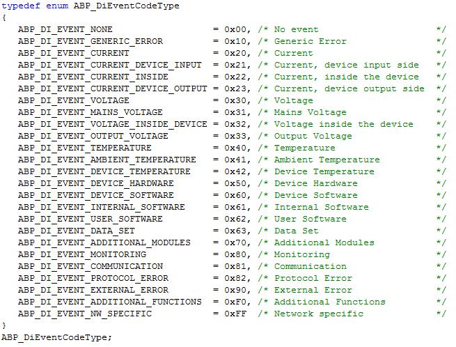
9 The Diagnostic Object 9 (28) For more information, see the Software Design Guide and the Network Guide of Anybus CompactCom 40 device. The device manufacturer has to define which event will be reported as a diagnostic event to the PLC and which severity has to be used. 3.3 Anybus CompactCom Event Codes The table below shows a list of the event codes applicable for Anybus CompactCom 40 device. The event code FFh is used if network specific diagnostics are reported (not considered within this application note).
10 PROFIBUS Diagnostics 10 (28) 4 PROFIBUS Diagnostics This section shows how PROFIBUS handles diagnostic data. PROFIBUS provides two types of diagnostics: Standard Diagnostics and Extended Diagnostics Standard Diagnostics provide general information about the device type and a flag when Extended Diagnostics are present (more details see Standard Diagnostics below). Extended Diagnostics report more precisely the origin of the error and the type of error and differs 3 types: Device Related Diagnostics, Identifier Related Diagnostics, Channel Related Diagnostics A Channel Related Diagnostics is related to one channel (signal input, or output) of a slave or a module of a slave. Identifier Related Diagnostics is related to modules of a slave. Within the scope of this application note is the Device Related Diagnostics. Device Related Diagnostics can be diagnostics alarm or status messages (details see below). For more details about diagnostics mechanisms of PROFIBUS DP Diagnostics see PROFIBUS profile guidelines part 3: Diagnostics, Alarms and Time Stamping. 4.1 Standard Diagnostics It consists of 6 octets. Their meaning is specified in the standard and is fixed. The diagnostics information is related to the communication layer and covers diagnostics scenarios such as the device identification, communication mode information (FREEZE, SYNC), readiness, availabilities, watchdogs, and parameterization and configuration faults.
11 PROFIBUS Diagnostics 11 (28)

12 PROFIBUS Diagnostics 12 (28) 4.2 Extended Diagnostics Here only the Device Related Diagnostics - one of the three possible types of Extended Diagnostics - is presented. Device Related Diagnostics is divided into two types: Diagnostics Alarm and Status Diagnostics Alarm The Diagnostics Alarm covers failures and errors of slave technology in a more detailed way as shown in the following: The CompactCom will create an Extended Diagnostics Alarm when the host application selects latching severities in the create event command.
13 PROFIBUS Diagnostics 13 (28) Status The Extended Diagnostics Status provides several different Status Types, e.g. Status_Message, Modul_Status, Within this application note the Status_Type Status_Message is in focus. The CompactCom will create an Extended Diagnostics Status with the Status_Type Status_ Message (value of Octet n+1 = 81h) when the host application selects recoverable / unrecoverable severities in the create event command (as long as the Modular Device Object is not implemented on host application side).


14 Application Example 5 14 (28) Application Example In this example we are using the Anybus CompactCom 40 Starter Kit in which we integrate the Anybus CompactCom 40 device. We use the host application example code for the windows platform simulating the host application. We also run the automation engineering tool SIMATIC STEP 7 by Siemens, for configuring the PLC. In this example we employ a S7 PLC-CPU PN/DP controller. The engineering tool will also report the diagnostic events sent by the CompactCom device to the PLC. The host application example code can be found here: Host application sample code. Fig. 1 Hardware Connection Overview The following section will explain what has to be done from the application side to make the CompactCom PROFIBUS device start to send Device Related Diagnostics to the network master. Each diagnostic event created by the host application - independent of whether the bit Extended Diagnostics of CMDExt[0] is set or not - will be reported as Extended Diagnostics on PROFIBUS. Anybus CompactCom 40 Diagnostic Events for PROFIBUS SCM

15 Application Example 15 (28) 5.1 Code Sample for Creating a Diagnostic Event This sample is intended to show how to create a diagnostic event in the CompactCom, using the CompactCom host application example code. The example below shows the structure of a create (03h) event command message that generates a diagnostic event defined as minor recoverable for the event code voltage. The section 6.1 will show how this event is displayed on STEP 7. The create (03h) event command above has created a diagnostic event including the severity code (minor recoverable (0x00)) and the event code (the voltage (0x30)). The message data field contains 8 octets. The first and second message data octets (indices 0 and 1) indicate the slot affected by the event -in this example they are set to the default value 0 -. The third and fourth message data octets (indices 2 and 3) reveal which process data (ADI) is involved here set to 0 because it is not associated with any particular ADI-. The fifth message data octet (index 4) signals which element of the ADI is concerned here set to 255 because it is associated with the entire ADI-. The sixth octet (index 5) tells which bit of the element is affected here set to 255 because it is associated with the entire element-. The seventh and eighth octets (indices 6 and 7) are reserved. See section 12.4 in the Anybus CompactCom 40 Software Design Guide and the network guide for more details.
 which will be displayed in the")
16 6 Relation Between Severity / Event Code and PROFIBUS GSD Files The PROFIBUS GSD file of the ABCC contains a section called Status diagnostic messages where alarm diagnostics or status messages are defined and in this area is done the relation between Severity and Event Code of the diagnostic event created by the host application and the text (Diag_Texts) which will be displayed in the engineering tool environment (SIMATIC STEP 7).
17 Between the keywords Unit_Diag_Area and Unit_Diag_Area_End the assignment of values in the bit fields to texts is done. These values are in decimal format. The Unit_Diag_Area is that part of the diagnostics frame which follows the header and counts the bits starting with 1 for bit 0 of the Type octet:


18 Bits 0 to 7 of the Unit_Diag_Area refer to Octet n+1 (Status_Type / Alarm_Type) and define the type of the diagnostics: alarm or status. In case of Status bit 7 is set, in case of Alarm bit 7 is cleared. Bits 8 to 15 of the Unit_Diag_Area refer to Octet n+2 (Slot number) and are not listed explicitly in the GSD file. The slot number is given by the host application when sending the create event command. Bits 16 to 23 of the Unit_Diag_Area refer to Octet n+3 (Status specifier / Alarm specifier). They inform if an event appears or disappears. This info is updated by the CompactCom internally, depending on if the host application sent a create or delete event command.
19 Bits 24 to 31 of the Unit_Diag_Area refer to Octet n+4 (Status_Data_Description, first octet) and are listed explicitly in the GSD file and correspond to the value of severity which is given by the host application when sending the create event command:

20 Bits 32 to 39 of the Unit_Diag_Area refer to Octet n+5 (Status_Data_Description, second octet) and are listed explicitly in the GSD file and correspond to the value of event code which is given by the host application when sending the create event command.
21


22 Readout of Diagnostics in STEP7 V (28) 7 Readout of Diagnostics in STEP7 V.5.5 A diagnostics event is created in the Anybus CompactCom 40 module. Start the diagnostics mode in Step 7 in going online by clicking on the button 1 in the picture. Then double-click at the left upper corner of the Anybus slave device on the button 2 represented in the picture by the square box attached to the PROFIBUS DP master. Fig. 2 Step 7 Hardware Diagnostics Fig. 3 Diagnostics Window The diagnostics window of the Anybus CompactCom 40 device will be displayed as shown in figure 4 and available diagnostic information can be read out. The integrated GSD file contains an area where the user can assign to each diagnostic event created a text. See also the application note How to configure an Anybus PROFIBUS Slave module with a Siemens Step 7 PLC showing how available diagnostics can be read out in Step 7.


23 Readout of Diagnostics in STEP7 V (28) 7.1 Severity: Minor Recoverable and Major Recoverable The picture presents five active diagnostic events defined as minor recoverable. The diagnostics window below shows the diagnostic information of an Anybus CompactCom 40 device. Fig. 4 Minor Recoverable On the left side of the picture for each active diagnostic event the corresponding text is displayed. The diagnostic window provides an alternative for reading out diagnostics by means of the button Hex. Format. When clicking on it the full diagnostic telegram is displayed in hexadecimal format as shown on the picture on the right. The diagnostic telegram is divided into two parts: the standard diagnostics and the extended diagnostics. The standard diagnostics contains always 6 octets as shown on the right picture in the red rectangle ( 08 0C ). The first three octets ( 08 0C 00 ) named Status 1, Status 2 and Status 3 contain status info. The fourth octet ( 05 ) indicates the master address that we can also see on the left picture. The fifth ( 18 ) and sixth octet ( 15 ) are used for ident number of the slave. In octet 1 (0x08) of the standard diagnostics bit 3 informs that this diagnostics contains extended diagnostics.
24 Readout of Diagnostics in STEP7 V (28) We will have a deeper look to the extended data now. The extended diagnostics (e.g ) fill the diagnostic telegram with additional blocks from the seventh octet on. According to Status, p. 13, these bytes have the following meaning: Octet 1, header 06h Defining type and length of the diagnostic block b defines the block length including the header (=> 6) b defines Device Related Diagnostics Octet 2, Status_Type 81h (Status_Message) Octet 3, Slot_Number 00h (event happened in slot 0) Octet 4, Status_Specifier 01h (event is coming) Octet 5...6, Status_Data_Description 00h 30h (user specific diag data) 00h: severity ( Minor, recoverable ) 30h: event code ( Voltage ) 00 stands for Device Related Diagnostics 01 stands for Identifier Related Diagnostics 10 stands for Channel Related Diagnostics The picture below shows two active diagnostic events defined as major recoverable. We proceed as for minor recoverable to evaluate the diagnostic telegram. The difference is in the user specific diag data by the severity (Octet 5) and the event code (Octet 6): Octet 5...6, Status_Data_Description 20h 20h (user specific diag data) 20h: severity ( Major, recoverable ) Fig. 5 Major Recoverable Diagnostic Messages

25 Readout of Diagnostics in STEP7 V (28) 7.2 Severity: Minor Unrecoverable Figure 6 shows an active diagnostic event defined as minor unrecoverable. In the extended diagnostic telegram we can read out from the user specific diag data the information about the severity of the event. Fig. 6 Minor Unrecoverable Diagnostic Status Message Octet 5 (0x10) represents the severity code which - in this case - means we are dealing with a minor unrecoverable event with event code (33h, Output Voltage ). This diagnostic event cannot be deleted. A reset of the CompactCom will delete this diagnostic event. 7.3 Severity: Major Unrecoverable The creation of a major unrecoverable diagnostic event causes the Anybus CompactCom 40 device to enter EXCEPTION state. This results into a disconnection of the device from the network. It is not possible to report any diagnostics. This is confirmed by the picture below. The diagnostics window indicates: the device is not available and since the device being disconnected from bus the diagnostics window of the slave will not display diagnostic events.


26 Readout of Diagnostics in STEP7 V (28) Fig. 7 Disconnection from Network 7.4 Severity: Minor Latching and Major Latching Fig. 8 Minor Latching Diagnostic Message The picture above presents an active minor latching diagnostic event on the left side of the picture and a deleted minor latching diagnostic event on the right side of the picture. The diagnostic telegram is also divided in standard diagnostics and extended diagnostics.
27 Readout of Diagnostics in STEP7 V (28) The standard diagnostics contains 6 octets like the other types of diagnostic events. In Octet 1 (0x00) of the standard diagnostics bit 3 is not set. This means that latching events will be handled as alarms whereas non-latching events will be handled as status messages. This is the main difference between latching and not latching diagnostic events. Octet 1, header 06h (Device Related Diagnostics) Octet 2, Status_Type 01h (Diagnostics_Alarm) Octet 3, Slot_Number 00h (event happened in slot 0) Octet 4, Status_Specifier 01h (event is coming) 02h (event is going) Octet 5...6, Status_Data_Description 50h 40h (user specific diag data) 50h: severity ( Minor, recoverable latching ) 40h: event code ( Temperature )
28 last page HMS Industrial Networks AB Box Halmstad, Sweden 2016 HMS Industrial Networks AB SCM / :28
Anybus CompactCom 40 Diagnostic Events for EtherNet/IP
 Anybus CompactCom 40 Diagnostic Events for EtherNet/IP SCM-1202 037 1.1 ENGLISH Important User Information Liability Every care has been taken in the preparation of this document. Please inform HMS Industrial
Anybus CompactCom 40 Diagnostic Events for EtherCAT SCM ENGLISH
 Anybus CompactCom 40 Diagnostic Events for EtherCAT SCM-1202 070 1.0 ENGLISH Important User Information Liability Every care has been taken in the preparation of this document. Please inform HMS Industrial
Anybus CompactCom 40 Diagnostic Events for Modbus-TCP APPLICATION NOTE
 Anybus CompactCom 40 Diagnostic Events for Modbus-TCP APPLICATION NOTE SCM-1202 039 1.1 ENGLISH Important User Information Liability Every care has been taken in the preparation of this document. Please
Anybus.NET. using TIA Portal with PROFIBUS APPLICATION NOTE
 Anybus.NET using TIA Portal with PROFIBUS APPLICATION NOTE SCM-1202-100-EN 1.0 ENGLISH Important User Information Liability Every care has been taken in the preparation of this document. Please inform
Anybus Communicator PROFINET
 Anybus Communicator PROFINET with Siemens S7-1500 PLC & TIA Portal APPLICATION NOTE SCM-1202-046 1.1 ENGLISH Important User Information Liability Every care has been taken in the preparation of this document.
Anybus X-gateway. PROFIBUS Master Interface NETWORK GUIDE SCM EN 1.0 ENGLISH
 Anybus X-gateway PROFIBUS Master Interface NETWORK GUIDE SCM-1202-104 EN 1.0 ENGLISH Important User Information Liability Every care has been taken in the preparation of this document. Please inform HMS
APPLICATION NOTE SCM ENGLISH
 Connect Anybus CompactCom to IIoT Applications Using Node-Red APPLICATION NOTE SCM-1300 014 1.1 ENGLISH Important User Information Liability Every care has been taken in the preparation of this document.
How to Configure DeviceNet with Anybus Configuration Manager (ACM) for DeviceNet APPLICATION NOTE DRAFT
 for DeviceNet APPLICATION NOTE DRAFT") How to Configure DeviceNet with Anybus Configuration Manager (ACM) for DeviceNet APPLICATION NOTE ENGLISH Important User Information Liability Every care has been taken in the preparation of this document.
How to Configure DeviceNet with Anybus Configuration Manager (ACM) for DeviceNet APPLICATION NOTE ENGLISH Important User Information Liability Every care has been taken in the preparation of this document.
FIP IO Slave. X-gateway Interface Addendum. Doc: HMSI Rev: Connecting DevicesTM
 X-gateway Interface Addendum FIP IO Slave Doc: HMSI-27-258 Rev: 2.00 Connecting DevicesTM HALMSTAD CHICAGO KARLSRUHE TOKYO BEIJING MILANO MULHOUSE COVENTRY PUNE COPENHAGEN HMS Industrial Networks Mailing
Anybus X-gateway EtherNet/IP
 Anybus X-gateway EtherNet/IP Rockwell Studio 5000 Generic Module APPLICATION NOTE SCM-1202-058 1.0 ENGLISH Important User Information Liability Every care has been taken in the preparation of this document.
Anybus CompactCom 40 PROFIBUS DP-V0/DP-V1 NETWORK GUIDE
 Anybus CompactCom 40 PROFIBUS DP-V0/DP-V1 NETWORK GUIDE HMSI-27-210-EN 2.3 ENGLISH Important User Information Liability Every care has been taken in the preparation of this document. Please inform HMS
Anybus CompactCom Option Board Freescale
 Installation Guide Anybus CompactCom Option Board Freescale Rev. 1.00 Connecting Devices TM HALMSTAD CHICAGO KARLSRUHE TOKYO BEIJING MILANO MULHOUSE COVENTRY PUNE COPENHAGEN HMS Industrial Networks Mailing
Anybus X-gateway. PROFINET IRT (2.32) Interface NETWORK GUIDE
 Interface NETWORK GUIDE") Anybus X-gateway PROFINET IRT (2.32) Interface NETWORK GUIDE SCM-1202-028-EN 1.1 ENGLISH Important User Information Liability Every care has been taken in the preparation of this document. Please inform
Anybus X-gateway PROFINET IRT (2.32) Interface NETWORK GUIDE SCM-1202-028-EN 1.1 ENGLISH Important User Information Liability Every care has been taken in the preparation of this document. Please inform
PROFIBUS Slave. X-gateway Interface Addendum. Doc: HMSI , Rev: Connecting Devices TM
 X-gateway Interface Addendum PROFIBUS Slave Connecting Devices TM HALMSTAD CHICAGO KARLSRUHE TOKYO BEIJING MILANO MULHOUSE COVENTRY PUNE COPENHAGEN HMS Industrial Networks Mailing address: Box 4126, 300
SOLUTION SHEET. KB en-us
 AnybusWirelessBoltasAccessPoint TotheeWONLANNetwork SOLUTION SHEET ENGLISH Important User Information Liability Every care has been taken in the preparation of this document. Please inform HMS Industrial
Anybus CompactCom Starter Kit REFERENCE GUIDE
 Anybus CompactCom Starter Kit REFERENCE GUIDE HMSI-27-224 EN 2.1 ENGLISH Important User Information Liability Every care has been taken in the preparation of this document. Please inform HMS Industrial
Anybus.NET Bridge PROFIBUS
 Anybus.NET Bridge PROFIBUS STARTUP GUIDE SCM-1203-046/SP2063 1.1 ENGLISH Important User Information Liability Every care has been taken in the preparation of this document. Please inform HMS Industrial
Network Guide Anybus CompactCom 40 PROFIBUS DP-V0/DP-V1
 Network Guide Anybus CompactCom 40 PROFIBUS DP-V0/DP-V1 Rev. 1.30 Connecting Devices TM HMS Industrial Networks Mailing address: Box 4126, 300 04 Halmstad, Sweden Visiting address: Stationsgatan 37, Halmstad,
STARTUP GUIDE. SP en-us ENGLISH
 Anybus PoEInjector 100 240VAC STARTUP GUIDE ENGLISH Important User Information Liability Every care has been taken in the preparation of this document. Please inform HMS Industrial Networks AB of any inaccuracies
X-gateway Interface Addendum CC-Link Slave Interface
 X-gateway Interface Addendum CC-Link Slave Interface Doc: HMSI-27-244, Rev: 2.00 Connecting DevicesTM HALMSTAD CHICAGO KARLSRUHE TOKYO BEIJING MILANO MULHOUSE COVENTRY PUNE COPENHAGEN HMS Industrial Networks
USB RS232 Cable Converter
 USB RS232 Cable Converter APPLICATION NOTE KB-0277-00 1.0 ENGLISH Important User Information Liability Every care has been taken in the preparation of this document. Please inform HMS Industrial Networks
REFERENCE GUIDE HMSI ENGLISH
 Anybus CompactCom Starter Kit REFERENCE GUIDE HMSI-27-224 2.0 ENGLISH Important User Information Liability Every care has been taken in the preparation of this document. Please inform HMS Industrial Networks
KPI Configuration APPLICATION NOTE KB EN 1.0
 KPI Configuration APPLICATION NOTE KB-0278-00 EN 1.0 ENGLISH Important User Information Liability Every care has been taken in the preparation of this document. Please inform HMS Industrial Networks SA
NTP Client Server Relay
 NTP Client Server Relay SOLUTION SHEET KB-0280-00 EN 1.0 ENGLISH Important User Information Liability Every care has been taken in the preparation of this document. Please inform HMS Industrial Networks
Enabling and Using OPC UA on Anybus CompactCom 40
 Enabling and Using OPC UA on Anybus CompactCom 40 APPLICATION NOTE SCM-1202-090 1.0 ENGLISH Important User Information Liability Every care has been taken in the preparation of this document. Please inform
WAN Connection Fallback
 For ewon Cosy 131 & ewon Flexy SOLUTION SHEET ENGLISH Important User Information Liability Every care has been taken in the preparation of this document. Please inform HMS Industrial Networks SA of any
CANopen Slave. X-gateway Interface Addendum. Doc: HMSI , Rev: Connecting Devices TM
 X-gateway Interface Addendum CANopen Slave Connecting Devices TM HALMSTAD CHICAGO KARLSRUHE TOKYO BEIJING MILANO MULHOUSE COVENTRY PUNE COPENHAGEN HMS Industrial Networks Mailing address: Box 4126, 300
EtherCAT Slave. X-gateway Interface Addendum. Doc: HMSI , Rev: Connecting Devices TM
 X-gateway Interface Addendum EtherCAT Slave Connecting Devices TM HALMSTAD CHICAGO KARLSRUHE TOKYO BEIJING MILANO MULHOUSE COVENTRY PUNE COPENHAGEN HMS Industrial Networks Mailing address: Box 4126, 300
SOFTWARE DESIGN GUIDE AUG ENGLISH
 ecatcher Mobile SOFTWARE DESIGN GUIDE AUG-0072-00 1.0 ENGLISH Important User Information Liability Every care has been taken in the preparation of this document. Please inform HMS Industrial Networks SA
Network Interface Appendix Anybus CompactCom PROFIBUS DP-V0
 Network Interface Appendix Anybus CompactCom PROFIBUS DP-V0 Rev. 1.02 Connecting Devices TM HMS Industrial Networks Mailing address: Box 4126, 300 04 Halmstad, Sweden Visiting address: Stationsgatan 37,
Anybus Communicator STARTUP GUIDE. IIoT. SP en-us ENGLISH
 Anybus Communicator IIoT STARTUP GUIDE ENGLISH Important User Information Liability Every care has been taken in the preparation of this document. Please inform HMS Industrial Networks AB of any inaccuracies
SAFETY MANUAL ENGLISH
 IXXAT Safe T100/PS Configuration Tool SAFETY MANUAL ENGLISH HMS Technology Center Ravensburg GmbH Helmut-Vetter-Straße 2 88213 Ravensburg Germany Tel.: +49 751 56146-0 Fax: +49 751 56146-29 Internet: www.hms-networks.de
Anybus Wireless Bridge II
 Anybus Wireless Bridge II STARTUP GUIDE SCM-1202-013/SP2167-EN 1.7 ENGLISH Important User Information Liability Every care has been taken in the preparation of this document. Please inform HMS Industrial
INpact Slave PCIe. Profibus/PROFINET IRT Fiber Optic/CC-Link/DeviceNet USER MANUAL EN 1.5
 INpact Slave PCIe Profibus/PROFINET IRT Fiber Optic/CC-Link/DeviceNet USER MANUAL 4.01.0321.20000-EN 1.5 ENGLISH Important User Information Liability Every care has been taken in the preparation of this
NT 200/420. Communication in Gateway Setup SOFTWARE DESIGN GUIDE ENGLISH
 CAN@net NT 200/420 Communication in Gateway Setup SOFTWARE DESIGN GUIDE 4.02.0332.20000 1.2 ENGLISH Important User Information Liability Every care has been taken in the preparation of this document. Please
RM30xx Profibus Brief instructions efector400
 RM30xx Profibus Brief instructions efector400 706414/00 Page 1 of 14 ifm efector gmbh Contents The description may contain deviations from the user system, because different manufacturers or software versions
1 SI CANopen CANopen Module for ET200S
 User Manual 1 SI CANopen CANopen Module for ET200S Rev. 1.32 Connecting Devices TM HMS Industrial Networks Mailing address: Box 4126, 300 04 Halmstad, Sweden Visiting address: Stationsgatan 37, Halmstad,
ControlNet Adapter. X-gateway Interface Addendum. Doc: HMSI Rev: Connecting Devices TM
 X-gateway Interface Addendum ControlNet Adapter Doc: HMSI-27-257 Rev: 2.00 Connecting Devices TM HALMSTAD CHICAGO KARLSRUHE TOKYO BEIJING MILANO MULHOUSE COVENTRY PUNE COPENHAGEN HMS Industrial Networks
The Cosy 131 User Guide USER MANUAL
 The Cosy 131 User Guide USER MANUAL UM-0004-00 EN 1.1 ENGLISH Important User Information Liability Every care has been taken in the preparation of this document. Please inform HMS Industrial Networks SA
How to configure a PROFIBUS network with NetTool for PROFIBUS
 How to configure a PROFIBUS network with NetTool for PROFIBUS www.anybus.com HMS Industrial Networks AB Page 1 (25) Document history Revision Date Description Responsible 1.00 2005-04-14 Created Patrik
Network Guide Anybus CompactCom 40 DeviceNet
 Network Guide Anybus CompactCom 40 DeviceNet Rev. 1.20 Connecting Devices TM HALMSTAD CHICAGO KARLSRUHE TOKYO BEIJING MILANO MULHOUSE COVENTRY PUNE COPENHAGEN HMS Industrial Networks Mailing address: Box
Anybus CompactCom. Host Application Implementation Guide HMSI ENGLISH
 Anybus CompactCom Host Application Implementation Guide HMSI-27-334 1.3 ENGLISH Important User Information Liability Every care has been taken in the preparation of this document. Please inform HMS Industrial
INSTALLATION GUIDE en-us ENGLISH
 VCIDriver forwindows INSTALLATION GUIDE ENGLISH Important User Information Liability Every care has been taken in the preparation of this document. Please inform HMS Industrial Networks of any inaccuracies
Anybus Wireless Bridge
 Anybus Wireless Bridge Ethernet-Bluetooth INSTALLATION GUIDE HMSI-27-203 SP2108 2.2 ENGLISH Important User Information Liability Every care has been taken in the preparation of this document. Please inform
Anybus CompactCom 30 SOFTWARE DESIGN GUIDE
 Anybus CompactCom 30 SOFTWARE DESIGN GUIDE HMSI-168-97 3.0 ENGLISH Important User Information Liability Every care has been taken in the preparation of this document. Please inform HMS Industrial Networks
STATUS COM FAIL CONFIGURATION ERROR READY RUN BUS HMS FIELDBUS SYSTEMS AB PILEFELTSGATAN SE HALMSTAD, SWEDEN
 User Manual Profibus Master Module Doc. No. H252-PDPM PDPM-1.31 PROCESS FIELD BUS BUS ON ERROR READY RUN CONFIGURATION STATUS COM FAIL HMS FIELDBUS SYSTEMS AB PILEFELTSGATAN 93-95 SE-302 50 HALMSTAD, SWEDEN
Easy Commissioning via SD Card & USB Drive
 Easy Commissioning via SD Card & USB Drive APPLICATION NOTE AUG-0062-00 EN 1.4 ENGLISH Important User Information Liability Every care has been taken in the preparation of this document. Please inform
PACSystems* RX3i IC695PBM300
 June 2010 PACSystems* RX3i IC695PBM300 PROFIBUS Master Module The PACSystems * RX3i PROFIBUS Master Module, IC695PBM300, allows the RX3i CPU to send and receive data on a PROFIBUS-DP network. The IC695PBM300
Network Certification
 Network Certification Policies and Instructions Rev. 3.02 Connecting DevicesTM +$/067$' &+,&$*2.$5/658+( 72.
Fieldbus Appendix Anybus-S Interbus 2Mbit/s Fibre Optic
 Fieldbus Appendix Anybus-S Interbus 2Mbit/s Fibre Optic SCM-1200-144 Rev. 1.03 Connecting Devices TM HMS Industrial Networks Mailing address: Box 4126, 300 04 Halmstad, Sweden Visiting address: Stationsgatan
Anybus Wireless Bolt RJ45 PoE
 Anybus Wireless Bolt RJ45 PoE STARTUP GUIDE SP2359 EN 1.1 ENGLISH Important User Information Liability Every care has been taken in the preparation of this document. Please inform HMS Industrial Networks
Fieldbus Appendix AnyBus-S FIPIO
 Fieldbus Appendix AnyBus-S FIPIO DOC.ID: ABS-FIP-1 Rev. 1.00 HMS Industrial Networks Germany Japan Sweden U.S.A + 49-721 - 96472-0 + 81-45 - 478-5340 + 46-35 - 17 29 20 + 1-773 - 404-2271 sales-ge@hms-networks.com
Device manual Profibus encoder. RM30xx RN30xx /00 06/2013
 Device manual Profibus encoder RM30xx RN30xx 706355/00 06/2013 Contents 1 Preliminary note................................................. 4 1.1 Symbols used...............................................
Operator Manual for Profibus
 PROCESS ANALYSERS SERVOPRO MultiExact Operator Manual for Profibus Part Number: Revision: Language: 05410007A 0 UK English This page intentionally blank LIST OF CONTENTS Section Page 1. DESCRIPTION AND
STARTUP GUIDE SCM /SP ENGLISH
 Anybus Wireless Bolt STARTUP GUIDE SCM-1202-006/SP2139 2.4 ENGLISH Important User Information Liability Every care has been taken in the preparation of this document. Please inform HMS Industrial Networks
Anybus CompactCom 40 SOFTWARE DESIGN GUIDE
 Anybus CompactCom 40 SOFTWARE DESIGN GUIDE HMSI-216-125-EN 3.6 ENGLISH Important User Information Liability Every care has been taken in the preparation of this document. Please inform HMS Industrial Networks
UTC Timestamp Logging
 UTC Timestamp Logging For Flexy as of Firmware 13.2s0 SOLUTION SHEET KB-0284-01 EN 1.0 ENGLISH Important User Information Liability Every care has been taken in the preparation of this document. Please
CANbridge NT. 200 and 420 USER MANUAL EN 1.3
 CANbridge NT 200 and 420 USER MANUAL 4.01.0331.20000-EN 1.3 ENGLISH Important User Information Liability Every care has been taken in the preparation of this document. Please inform HMS Industrial Networks
FR-IB100/PCIe. FlexRay PCI Express Interface Card USER MANUAL ENGLISH
 FR-IB100/PCIe FlexRay PCI Express Interface Card USER MANUAL 4.01.0103.20000 2.0 ENGLISH Important User Information Liability Every care has been taken in the preparation of this document. Please inform
Using PROFIsafe modules in combination with PROFIBUS-DP and PROFINET Application note
 Using PROFIsafe modules in combination with PROFIBUS-DP and PROFINET, English Version 03.01.01 2 General Copyright 2010 by WAGO Kontakttechnik GmbH & Co. KG All rights reserved. WAGO Kontakttechnik GmbH
USB-to-CAN V2. Compact Embedded Automotive Professional USER MANUAL ENGLISH
 USB-to-CAN V2 Compact Embedded Automotive Professional USER MANUAL 4.01.0280.20000 2.3 ENGLISH Important User Information Liability Every care has been taken in the preparation of this document. Please
ST (6ES7132-6FD00-0BB1)
") SIMATIC ET 200SP Digital output module DQ 4x24..230VAC/2A ST (6ES7132-6FD00-0BB1) Manual Edition 02/2014 Answers for industry. DQ 4x24..230VAC/2A ST Preface Guide to documentation 1 SIMATIC ET 200SP DQ
SIMATIC ET 200SP Digital output module DQ 4x24..230VAC/2A ST (6ES7132-6FD00-0BB1) Manual Edition 02/2014 Answers for industry. DQ 4x24..230VAC/2A ST Preface Guide to documentation 1 SIMATIC ET 200SP DQ
FLB G (Verizon) Extension Card INSTALLATION GUIDE
 Extension Card INSTALLATION GUIDE") FLB 3203 4G (Verizon) Extension Card INSTALLATION GUIDE IG-0025-00 1.0 ENGLISH Important User Information Liability Every care has been taken in the preparation of this document. Please inform HMS Industrial
FLB 3203 4G (Verizon) Extension Card INSTALLATION GUIDE IG-0025-00 1.0 ENGLISH Important User Information Liability Every care has been taken in the preparation of this document. Please inform HMS Industrial
Network Certification Policies and Instructions HMSI ENGLISH
 Network Certification Policies and Instructions HMSI-168-5 4.0 ENGLISH Important User Information Liability Every care has been taken in the preparation of this document. Please inform HMS Industrial Networks
Anybus X-gateway USER MANUAL
 Anybus X-gateway USER MANUAL HMSI-27-262 3.0 ENGLISH Important User Information Liability Every care has been taken in the preparation of this document. Please inform HMS Industrial Networks AB of any
AnyBus -X Modbus Plus Slave
 Network Interface Addendum AnyBus -X Modbus Plus Slave Doc.Id. SCM-1200-069 Rev. 1.02 HMS Industrial Networks AB Germany Japan Sweden U.S.A. France Italy China + 49-721 - 96472-0 + 81-45 - 478-5340 + 46-35
DANGER indicates that death or severe personal injury will result if proper precautions are not taken.
 Communication module CM DP (6ES7545-5DA00-0AB0) SIMATIC ET 200SP Communication module CM DP (6ES7545-5DA00-0AB0) Manual Preface ET 200SP Documentation Guide 1 Product overview 2 Wiring 3 Programming 4
USB-to-CAN FD. Compact Embedded Automotive USER MANUAL ENGLISH
 USB-to-CAN FD Compact Embedded Automotive USER MANUAL 4.01.0350.20000 1.1 ENGLISH Important User Information Liability Every care has been taken in the preparation of this document. Please inform HMS Industrial
Netbiter EC300 Series
 Netbiter EC300 Series USER MANUAL SCM-1202-012 2.2 ENGLISH Important User Information Liability Every care has been taken in the preparation of this document. Please inform HMS Industrial Networks AB of
Anybus-CC Technical Introduction
 Anybus-CC Technical Introduction Anybus Background From the beginning the functionality of an industrial network interface was primarily designed to exchange process data (I/O data). When Anybus was originally
BB2 Profibus DP option
 BB2 Profibus DP option 2017-09-06 MANUS09/17 VER 1.03 Table of contents 1. Introduction... 3 2. A few words about this manual... 3 3. Fieldbus introduction... 3 Network Overview... 3 4. Unpacking... 4
INpact Slave PCIe. Industrial Ethernet PCIexpress Interface USER MANUAL ENGLISH
 INpact Slave PCIe Industrial Ethernet PCIexpress Interface USER MANUAL 4.01.0320.20000 1.7 ENGLISH Important User Information Liability Every care has been taken in the preparation of this document. Please
USER MANUAL en-us ENGLISH
 CANFDRepeater CAN-CR100,CAN-CR110/FO,CAN-CR120/HV,CAN-CR300 USER MANUAL ENGLISH Important User Information Liability Every care has been taken in the preparation of this document. Please inform HMS Industrial
Anybus CompactCom 40. EtherNet/IP Transparent Ethernet NETWORK GUIDE
 Anybus CompactCom 40 EtherNet/IP Transparent Ethernet NETWORK GUIDE SCM-1202-019-EN 1.6 ENGLISH Important User Information Liability Every care has been taken in the preparation of this document. Please
Anybus CompactCom 30. CANopen NETWORK GUIDE HMSI EN 4.1 ENGLISH
 Anybus CompactCom 30 CANopen NETWORK GUIDE HMSI-168-78 EN 4.1 ENGLISH Important User Information Liability Every care has been taken in the preparation of this document. Please inform HMS Industrial Networks
Observe all necessary safety precautions when controlling the soft starter remotely. Alert personnel that machinery may start without warning.
 MCD Profibus Module Instructions Important User Information Installation Instruction: MCD Profibus Module Order Code: 175G9001 1. Important User Information Observe all necessary safety precautions when
Product Information Mixed. Configuration ET 200SP / ET 200AL SIMATIC. ET 200SP Product Information Mixed Configuration ET 200SP / ET 200AL.
 Product Information Mixed Configuration ET 200SP / ET 200AL SIMATIC ET 200SP Product Information Mixed Configuration ET 200SP / ET 200AL Product Information Preface Application planning 1 Mounting 2 Connection
PROFIsafe modules V2 ipar 75x-66x/ WAGO Safety-Editor-75x Quickstart
 PROFIsafe modules V2 ipar 75x-66x/000-003 WAGO Safety-Editor-75x Quickstart Version 06.00.00 2 General Copyright 2010 by WAGO Kontakttechnik GmbH & Co. KG All rights reserved. WAGO Kontakttechnik GmbH
ControlNet Adapter Interface
 X-gateway Interface Addendum ControlNet Adapter Interface Rev. 1.10 HMS Industrial Networks AB Germany Japan Sweden U.S.A + 49-721 - 96472-0 + 81-45 - 478-5340 + 46-35 - 17 29 20 + 1-773 - 404-3486 ge-sales@hms-networks.com
User Manual Anybus Communicator for CC-Link IE Field
 User Manual Anybus Communicator for CC-Link IE Field Doc: HMSI-27-278 Rev. 1.13 Connecting Devices TM HMS Industrial Networks Mailing address: Box 4126, 300 04 Halmstad, Sweden Visiting address: Stationsgatan
MCD 200 Series. MCD 200 DEVICENET Module OPERATING INSTRUCTIONS. MCD 200 DEVICENET Module. Order Code: 175G9002. Adjustment.
 Installation OPERATING INSTRUCTIONS Order Code: 175G9002 Adjustment 35 mm (1.38 inches) Control power and mains supply must be removed from the MCD 200 before attachment or removal of an accessory module.
Anybus CompactCom. Host Application Implementation Guide. Doc.Id. HMSI Doc. Rev Connecting DevicesTM
 Anybus CompactCom Doc. Rev. 1.10 Connecting DevicesTM +$/067$' &+,&$*2.$5/658+( 72.
Power module PM-E DC24V/8A RO SIMATIC. ET 200S distributed I/O Power module PM-E DC24V/8A RO (6ES7138-4CA80-0AB0) Preface. Properties.
 Preface. Properties.") Power module PM-E DC24V/8A RO (6ES7138-4CA80-0AB0) SIMATIC ET 200S distributed I/O Power module PM-E DC24V/8A RO (6ES7138-4CA80-0AB0) Preface Properties 1 Parameters 2 Diagnostics 3 Configuring 4 Manual
Power module PM-E DC24V/8A RO (6ES7138-4CA80-0AB0) SIMATIC ET 200S distributed I/O Power module PM-E DC24V/8A RO (6ES7138-4CA80-0AB0) Preface Properties 1 Parameters 2 Diagnostics 3 Configuring 4 Manual
Interface module IM DP (6ES7157-1AA00-0AB0) SIMATIC. ET 200AL Interface module IM DP (6ES7157-1AA00-0AB0) Preface. Documentation guide
 SIMATIC. ET 200AL Interface module IM DP (6ES7157-1AA00-0AB0) Preface. Documentation guide") Interface module IM 157-1 DP (6ES7157-1AA00-0AB0) SIMATIC ET 200AL Interface module IM 157-1 DP (6ES7157-1AA00-0AB0) Manual Preface Documentation guide 1 Product overview 2 Wiring 3 Parameters 4 Configuration
Interface module IM 157-1 DP (6ES7157-1AA00-0AB0) SIMATIC ET 200AL Interface module IM 157-1 DP (6ES7157-1AA00-0AB0) Manual Preface Documentation guide 1 Product overview 2 Wiring 3 Parameters 4 Configuration
Copyright: December 2017 Nidec Issue: E
 General Information The manufacturer accepts no liability for any consequences resulting from inappropriate, negligent or incorrect installation or adjustment of the optional parameters of the equipment
INpact Slave PCIe. Industrial Ethernet PCIexpress Interface USER MANUAL ENGLISH
 INpact Slave PCIe Industrial Ethernet PCIexpress Interface USER MANUAL 4.01.0320.20000 1.3 ENGLISH Important User Information Liability Every care has been taken in the preparation of this document. Please
Getting Started - Startdrive. Startdrive SINAMICS. Introduction 1. Connecting the drive unit to the PC. Creating a project 3
 Getting Started - Startdrive Introduction 1 Connecting the drive unit to the PC 2 Startdrive SINAMICS Getting Started Creating a project 3 Going online and incorporating devices 4 Commissioning the drive
RMx621. Appendix to the operating manual
 Appendix to the operating manual RMx621 DP-slave module ( PROFIBUS-coupler ) from V2.01.00 Connecting the RMx621 to PROFIBUS DP via the RS485 serial interface using the external module (HMS AnyBus Communicator
User Manual Anybus Communicator for DeviceNet
 User Manual Anybus Communicator for DeviceNet Doc. Id. SCM-1200-098 Rev. 3.01 Connecting Devices TM HMS Industrial Networks Mailing address: Box 4126, 300 04 Halmstad, Sweden Visiting address: Stationsgatan
Network Interface Appendix Anybus -CompactCom Passive RS-485/422
 Network Interface Appendix Anybus -CompactCom Passive RS-485/422 Rev. 1.01 Connecting Devices TM HMS Industrial Networks Mailing address: Box 4126, 300 04 Halmstad, Sweden Visiting address: Stationsgatan
LB/FB8X09* / LB/FB8X05*
 GETTING STARTED Connecting Remote I/O Stations with Com Unit LB/FB8X09* / LB/FB8X05* to Siemens PLC (S7-300) via PROFIBUS 1 Contents 1. INTRODUCTION... 3 2. PREPARING FOR CONFIGURATION... 3 2.1. DOWNLOADING
Anybus-S CC-Link. Fieldbus Appendix. Rev HMS Industrial Networks AB. Germany Japan Sweden U.S.A UK
 Fieldbus Appendix Anybus-S CC-Link Rev. 1.51 HMS Industrial Networks AB Germany Japan Sweden U.S.A UK +49-721 - 96472-0 +81-45 - 478-5340 +46-35 - 17 29 20 +1-773 - 404-3486 +44-1908 - 359301 sales-ge@hms-networks.com
Network Interface Appendix Anybus -CompactCom DeviceNet
 Network Interface Appendix Anybus -CompactCom DeviceNet Rev. 1.06 HMS Industrial Networks AB Germany Japan Sweden U.S.A + 49-721 - 96472-0 + 81-45 - 478-5340 + 46-35 - 17 29 20 + 1-773 - 404-3486 ge-sales@hms-networks.com
Softstarters Type PSTX Fieldbus communication, Anybus CompactCom DeviceNet
 Softstarters Type PSTX Fieldbus communication, Anybus CompactCom DeviceNet 1SFC132084M0201 June 2017 Power and productivity for a better world 1SFC132084M0201 1SFC132084M0201 INFORMATION When fastening
User Manual Anybus Communicator for CANopen
 User Manual Anybus Communicator for CANopen Doc. Id. SCM-1200-099 Rev. 3.01 Connecting Devices TM HMS Industrial Networks Mailing address: Box 4126, 300 04 Halmstad, Sweden Visiting address: Stationsgatan
Profibus Getting Started User's Manual
 www.infoplc.net Profibus Getting Started User's Manual Version: 1.00 (July 2006) Model No.: MAPBGETST-ENG We reserve the right to change the contents of this manual without warning. The information contained
Classic IO Modules (M12) for Profibus DP
 for Profibus DP") User s Manual Classic IO Modules (M12) for Profibus DP BradControl from ELCO Release 1.0 draft 7 February 16 th, 2008 i Revision History Date Author Document # Doc. Location Changes Revision 1 st Nov.
User s Manual Classic IO Modules (M12) for Profibus DP BradControl from ELCO Release 1.0 draft 7 February 16 th, 2008 i Revision History Date Author Document # Doc. Location Changes Revision 1 st Nov.
RMx621 /FML621. Appendix to the operating manual
 Appendix to the operating manual RMx621 /FML621 DP-slave module ( PROFIBUS-coupler ) from V2.01.00 Connecting the RMx621 /FML621 to PROFIBUS DP via the RS485 serial interface using the external module
SIMATIC. ET 200SP DQ 4x VAC/2A ST digital output module (6ES7132-6FD00-0BB1) Preface. Guide to documentation. Product overview.
 Preface. Guide to documentation. Product overview.") Preface Guide to documentation 1 SIMATIC ET 200SP DQ 4x24..230VAC/2A ST digital output module (6ES7132-6FD00-0BB1) Manual Product overview 2 Wiring 3 Parameter assignment/addressing 4 Interrupts/diagnostics
Preface Guide to documentation 1 SIMATIC ET 200SP DQ 4x24..230VAC/2A ST digital output module (6ES7132-6FD00-0BB1) Manual Product overview 2 Wiring 3 Parameter assignment/addressing 4 Interrupts/diagnostics
PROFIBUS MODULE (CB15) English Operating Instructions. Contents. Warning and Caution Notes
 English Operating Instructions. Contents. Warning and Caution Notes") Contents Warning and Caution Notes 1. OVERVIEW 1.1 Description and Features 1.2 Application on a PROFIBUS Link 2. INSTALLATION 2.1 Connecting the Bus Cable 2.1.1 Terminals 2.1.2 Bus Cabling 2.2 EMC Measures
Contents Warning and Caution Notes 1. OVERVIEW 1.1 Description and Features 1.2 Application on a PROFIBUS Link 2. INSTALLATION 2.1 Connecting the Bus Cable 2.1.1 Terminals 2.1.2 Bus Cabling 2.2 EMC Measures