Datalogic Scanning, Inc. 959 Terry Street Eugene, Oregon Telephone: (541) Fax: (541)
|
|
|
- Ashlee Kelly
- 6 years ago
- Views:
Transcription
1
2 Datalogic Scanning, Inc. 959 Terry Street Eugene, Oregon Telephone: (541) Fax: (541) An Unpublished Work - All rights reserved. No part of the contents of this documentation or the procedures described therein may be reproduced or transmitted in any form or by any means without prior written per-mission of Datalogic Scanning, Inc. or its subsidiaries or affiliates ("Datalogic" or Datalogic Scanning ). Owners of Datalogic products are hereby granted a nonexclusive, revocable license to reproduce and transmit this documentation for the purchaser's own internal business purposes. Purchaser shall not remove or alter any proprietary notices, including copyright notices, contained in this documentation and shall ensure that all notices appear on any reproductions of the documentation. Should future revisions of this manual be published, you can acquire printed versions by contacting your Datalogic representative. Electronic versions may either be downloadable from the Datalogic website ( or provided on appropriate media. If you visit our website and would like to make comments or suggestions about this or other Datalogic publications, please let us know via the "Contact Datalogic" page. Disclaimer Datalogic has taken reasonable measures to provide information in this manual that is complete and accurate, however, Datalogic reserves the right to change any specification at any time without prior notice. Datalogic is a registered trademark of Datalogic S.p.A. in many countries and the Datalogic logo is a trademark of Datalogic S.p.A. all licensed to Datalogic Scanning, Inc. All other trademarks and trade names referred to herein are property of their respective owners. 19/10/2007
3 CONTENTS 1 STAR MODEM CONFIGURATION... 1 RS232 PARAMETERS... 2 Baud Rate... 3 Parity... 4 Data Bits... 4 Stop Bits... 5 Handshaking... 5 ACK/NACK Protocol... 6 FIFO... 6 Inter-Character Delay... 7 RX Timeout... 7 Frame Packing... 8 WEDGE PARAMETERS... 9 Keyboard Nationality Caps Lock Num Lock Inter-Character Delay Inter-Code Delay Keyboard Setting Control Character Emulation PEN EMULATION Operating Mode Minimum Output Pulse Overflow Conversion To Code 39 and Code Output Level Idle Level Inter-Block Delay DATA FORMAT Code Identifier Custom Code Identifier Header Terminator Header Position Code Length Tx Address Stamping Address Delimiter iii
4 RADIO PARAMETERS RF Baud Rate Transmission Mode Radio Protocol Timeout ACK/NACK From Remote Host Single Store Beacon REFERENCES Radio and Serial Communication Controls RS232 Parameters Handshaking ACK/NACK Protocol RX Timeout FIFO Frame Packing PEN Emulation Parameters Minimum Output Pulse Overflow Conversion to Code 39 and Code Output and Idle Levels Inter-Block Delay Data Format Header/Terminator Selection Header Position Address Stamping Address Delimiter Radio Parameters RF Baud Rate (not for USA Model) Transmission Mode (Client only) Radio Protocol Timeout (Client only) Single Store (Client only) ACK/NACK From Remote Host (Client only) Beacon (Client only) A CODE IDENTIFIER TABLE B HEX AND NUMERIC TABLE GLOSSARY iv
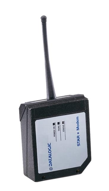
5 STAR Modem CONFIGURATION 1 STAR MODEM CONFIGURATION Once STAR Modem is setup (see Chapter 3 in STAR Modem Reference Manual), you can change the default parameters to meet your application needs by reading the barcodes with a Datalogic RF device and sending them to the modem via radio. This configuration procedure is particularly advised when working with Pen Emulation/Wedge interface connection. In this manual, the configuration parameters are divided into logical groups making it easy to find the desired function based on its reference group. For this configuration procedure follow the steps given at the beginning of each parameter group. The first three groups are for Standard Interface parameter configuration: RS232 WEDGE PEN EMULATION The following parameter groups are common to all interface applications: DATA FORMAT parameters regard the messages sent to the Host system for all interfaces except Pen Emulation. RADIO PARAMETERS allow configuration of radio protocol parameters. NOTE Gryphon M rel. 2.4, DRAGON M rel. 1.1 and RF Terminals loading STAR&Play rel. 1.0 do not allow to send via radio some of the configuration parameters to STAR Modem. 1
6 RS232 PARAMETERS BAUD RATE PARITY DATA BITS STOP BITS HANDSHAKING ACK/NACK PROTOCOL FIFO INTER-CHARACTER DELAY RX TIMEOUT FRAME PACKING 1. Read Enter Configuration code ONCE, available at the top of each page. 2. Read the configuration codes from the desired groups. = Read the code and follow the procedure given 3. Read the Exit and Save Configuration code ONCE, available at the top of each page. 2
7 Enter configuration RS232 Exit and Save configuration BAUD RATE 150 baud 600 baud 2400 baud 9600 baud baud 300 baud 1200 baud 4800 baud baud baud 3
8 Enter configuration RS232 Exit and Save configuration PARITY none even parity odd parity DATA BITS 7 bits 8 bits 9 bits 4
9 Enter configuration RS232 Exit and Save configuration STOP BITS 1 stop bit 2 stop bits HANDSHAKING disable software (XON/XOFF) modem (RTS/CTS) hardware (RTS/CTS) RTS always ON See par for details. 5
10 Enter configuration RS232 Exit and Save configuration ACK/NACK PROTOCOL disabled enable ACK/NACK enable DATA/NACK See par for details. FIFO disable enable See par for details. 6
11 Enter configuration RS232 Exit and Save configuration INTER-CHARACTER DELAY delay between characters transmitted to Host Read 2 numbers from the Appendix B where: 00 = DELAY disabled = DELAY from 1 to 99 milliseconds delay disabled RX TIMEOUT timeout control in reception from Host Read 2 numbers from the Appendix B where: 00 = TIMEOUT disabled = TIMEOUT from.1 to 9.9 seconds rx timeout 5 seconds See par and par for details. 7
12 Enter configuration RS232 Exit and Save configuration FRAME PACKING frame + [CR] [STX] + Len + frame + [CR] frame after timeout See par for details. 8
13 WEDGE PARAMETERS KEYBOARD NATIONALITY CAPS LOCK NUM LOCK INTER-CHARACTER DELAY INTER-CODE DELAY KEYBOARD SETTING WEDGE CONTROL CHARACTER EMULATION 1. Read Enter Configuration code ONCE, available at the top of each page. 2. Read the configuration codes from the desired groups. = Read the code and follow the procedure given 3. Read the Exit and Save Configuration code ONCE, available at the top of each page. 9
14 Enter configuration WEDGE Exit and Save configuration KEYBOARD NATIONALITY Belgian French Italian Swedish English German Spanish USA 10
15 Enter configuration WEDGE Exit and Save configuration CAPS LOCK caps lock OFF caps lock ON Select the appropriate code to match your keyboard caps lock status. Note: For PC Notebook interface selections, the caps lock status is automatically recognized, therefore this command is not necessary. NUM LOCK toggle num lock num lock unchanged This selection is used together with the Alt Mode interface selection for AT or Notebook PCs. It changes the way the Alt Mode procedure is executed, therefore it should be set as follows: if your keyboard Num Lock is normally on use num lock unchanged if your keyboard Num Lock is normally off use toggle num lock In this way the device will execute the Alt Mode procedure correctly for your application. 11
16 Enter configuration WEDGE Exit and Save configuration INTER-CHARACTER DELAY delay between characters transmitted to Host Read 2 numbers from the Appendix B where: 00 = DELAY disabled = DELAY from 1 to 99 milliseconds delay disabled INTER-CODE DELAY delay between codes transmitted to Host Read 2 numbers from the Appendix B where: 00 = DELAY disabled = DELAY from 1 to 99 seconds delay disabled 12
17 Enter configuration WEDGE Exit and Save configuration KEYBOARD SETTING ALPHANUMERIC KEYBOARD SETTING The reader can be used with terminals or PCs with various keyboard types and nationalities through a simple keyboard setting procedure. The type of computer or terminal must be selected before activating the keyboard setting command. Keyboard setting consists of communicating to the reader how to send data corresponding to the keyboard used in the application. The keys must be set in a specific order. Press and release a key to set it. Some characters may require more than one key pressed simultaneously during normal use (refer to the manual of your PC or terminal for keyboard use). The exact sequence must be indicated to the reader in this case pressing and releasing the different keys. Example: If one has to press the "Shift" and "4" keys simultaneously on the keyboard to transmit the character "$" to the video, to set the "$", press and release "Shift" then press and release "4". Each pressed and released key must generate a yellow LED blinking on the device, otherwise repress the key. Never press more than one key at the same time, even if this corresponds to the normal use of your keyboard. Press "Backspace" to correct a wrong key entry. Note: "CAPS LOCK" and "NUM LOCK" must be off before starting the keyboard setting procedure. "SHIFT" must be repressed for each character and cannot be substituted by "CAPS LOCK". setting the alphanumeric keyboard Read the code above. press the keys shown in the following table according to their numerical order. Some ASCII characters may be missing as this depends on the type of keyboard: these are generally particular characters relative to the various national symbologies. In this case: The first 4 characters (Shift, Alt, Ctrl, and Backspace) can only be substituted with keys not used, or substituted with each other. characters can be substituted with other single symbols (e.g. "SPACE") even if not included in the barcode set used. characters can be substituted with others corresponding to your keyboard. 13
18 WEDGE 01 : Shift 02 : Alt 03 : Ctrl 04 : Backspace 05 : SPACE 28 : 7 51 : N 06 :! 29 : 8 52 : O 07 : " 30 : 9 53 : P 08 : # 31 : : 54 : Q 09 : $ 32 : ; 55 : R 10 : % 33 : < 56 : S 11 : & 34 : = 57 : T 12 : ' 35 : > 58 : U 13 : ( 36 :? 59 : V 14 : ) : W 15 : * 38 : A 61 : X 16 : + 39 : B 62 : Y 17 :, 40 : C 63 : Z 18 : - 41 : D 64 : [ 19 :. 42 : E 65 : \ 20 : / 43 : F 66 : ] 21 : 0 44 : G 67 : ^ 22 : 1 45 : H 68 : _ (underscore) 23 : 2 46 : I 69 : ` 24 : 3 47 : J 70 : { 25 : 4 48 : K 71 : 26 : 5 49 : L 72 : } 27 : 6 50 : M 73 : ~ 74 : DEL During the keyboard setting the red LED on the modem always blinks, the yellow LED stays on and blinks off only each time a key is pressed, while the green LED stays on and blinks off only each time the Backspace key is pressed. Once the last key has been pressed, the yellow LED stays off indicating the keys have been registered, while the green LED stays on again. Read the Exit and Save configuration barcode to end the procedure. 14
19 Enter configuration WEDGE Exit and Save configuration CONTROL CHARACTER EMULATION Ctrl + Shift + Key Ctrl + Key 15
20 PEN EMULATION OPERATING MODE MINIMUM OUTPUT PULSE CONVERSION TO CODE 39 AND CODE 128 OVERFLOW OUTPUT LEVEL IDLE LEVEL INTER-BLOCK DELAY 1. Read the Enter Configuration code ONCE, available at the top of each page. 2. Read the configuration codes from the desired groups. = Read the code and follow the procedure given 3. Read the Exit and Save Configuration code ONCE, available at the top of each page. 16
21 PEN EMULATION OPERATING MODE The operating mode parameters are complete commands and do not require reading the Enter and Exit configuration codes. interpret mode Interprets commands without sending them to the decoder. transparent mode Sends commands to the decoder without interpreting them. 17
22 Enter configuration PEN EMULATION Exit and Save configuration MINIMUM OUTPUT PULSE high resolution code emulation 200 μs 400 μs 600 μs 800 μs 1 ms 1.2 ms low resolution code emulation See par for details. 18
23 Enter configuration PEN EMULATION Exit and Save configuration OVERFLOW narrow medium wide See par for details. CONVERSION TO CODE 39 AND CODE 128 enable conversion to Code 39 enable conversion to Code 128 See par for details. 19
24 Enter configuration PEN EMULATION Exit and Save configuration OUTPUT LEVEL normal (white = logic level 0) inverted (white = logic level 1) See par for details. IDLE LEVEL normal (black level) inverted (white level) See par for details. 20
25 Enter configuration PEN EMULATION Exit and Save configuration INTER-BLOCK DELAY delay between character blocks transmitted to Host Read 2 numbers from the Appendix B where 00 = DELAY disabled = DELAY from.1 to 9.9 seconds DELAY disabled See par for details 21
26 DATA FORMAT NOT FOR PEN INTERFACES CODE IDENTIFIER CUSTOM CODE IDENTIFIER HEADER TERMINATOR HEADER POSITION CODE LENGTH TX ADDRESS STAMPING ADDRESS DELIMITER 1. Read Enter Configuration code ONCE, available at the top of each page. 2. Read the configuration codes from the desired groups. = Read the code and follow the procedure given 3. Read Exit and Save Configuration code ONCE, available at the top of each page. 22
27 CODE IDENTIFIER TABLE CODE AIM STANDARD DATALOGIC STANDARD Custom 2/5 interleaved ] I y N 2/5 industrial ] X y P 2/5 normal 5 bars ] S y O 2/5 matrix 3 bars ] X y Q EAN 8 ] E 4 A EAN 13 ] E 0 B UPC A ] X y C UPC E ] X y D EAN 8 with 2 ADD ON ] E 5 J EAN 8 with 5 ADD ON ] E 6 K EAN 13 with 2 ADD ON ] E 1 L EAN 13 with 5 ADD ON ] E 2 M UPC A with 2 ADD ON ] X y F UPC A with 5 ADD ON ] X y G UPC E with 2 ADD ON ] X y H UPC E with 5 ADD ON ] X y I Code 39 ] A y V Code 39 Full ASCII ] A y W CODABAR ] F y R ABC CODABAR ] X y S Code 128 ] C y T EAN 128 ] C y k ISBT 128 ] C4 f Code 93 ] G y U CIP/39 ] X y Y CIP/HR ] X y e Code 32 ] X y X Codablock-A ] O 6 n Codablock-F Std ] O 4 l Codablock-F EAN ] O 5 m MSI ] M y Z Plessey Standard ] P 0 a Plessey Anker ] P 1 o Telepen ] X 0 d Delta IBM ] X 0 c Code 11 ] H y b Code 16K ] K 0 p Code 49 ] T y q PDF417 ] L 0 r 23
28 AIM standard identifiers are not defined for all codes: the X identifier is assigned to the code for which the standard is not defined. The y value depends on the selected options (check digit tested or not, check digit tx or not, etc.). When customizing the Datalogic Standard code identifiers, 1 or 2 identifier characters can be defined for each code type. If only 1 identifier character is required, the second character must be selected as FF (disabled). The code identifier can be singly disabled for any code by simply selecting FF as the first identifier character. Write in the Custom character identifiers in the table above for your records. 24
29 Enter configuration DATA FORMAT Exit and Save configuration CODE IDENTIFIER disable Datalogic standard AIM standard custom 25
30 Enter configuration DATA FORMAT Exit and Save configuration CUSTOM CODE IDENTIFIER define custom code identifier(s) Read the above code. (Code Identifiers default to Datalogic standard, see table on previous page). Select the code type from the code table in Appendix A for the identifier you want to change. You can define 1 or 2 identifier characters for each code type. If only 1 identifier character is required, the second character must be selected as FF (disabled). Read the hexadecimal value corresponding to the character(s) you want to define as identifiers for the code selected in step : valid characters are in the range 00-FE. Example: To define Code 39 Code Identifier Read define custom code identifier(s) Code F F
31 Enter configuration DATA FORMAT Exit and Save configuration HEADER no header two character header four character header six character header eight character header one character header three character header five character header seven character header After selecting one of the desired Header codes, read the character(s) from the Appendix B. Valid characters for all readers are in the range: 00-FE Example: To define Header = AB 27
32 Enter configuration DATA FORMAT Exit and Save configuration two character header Read For more details about default and WEDGE Interface Extended Keyboard values, see par
33 Enter configuration DATA FORMAT Exit and Save configuration TERMINATOR no terminator two character terminator four character terminator six character terminator eight character terminator one character terminator three character terminator five character terminator seven character terminator After selecting one of the desired Terminator codes, read the character(s) from the Appendix B. Valid characters for all readers are in the range: 00-FE Example: To define Terminator = CR LF 29
34 Enter configuration DATA FORMAT Exit and Save configuration two character terminator 0 D 0 A Read For more details about default and WEDGE Interface Extended Keyboard values, see par
35 Enter configuration DATA FORMAT Exit and Save configuration HEADER POSITION first frame field before message field See par. 0 for details. CODE LENGTH TX code length not transmitted code length transmitted in variable-digit format code length transmitted in fixed 4-digit format The code length is transmitted in the message after the Headers and Code Identifier characters. The code length is calculated after performing any field adjustment operations. 31
36 Enter configuration DATA FORMAT Exit and Save configuration ADDRESS STAMPING disable address stamping enable address stamping See par for details. ADDRESS DELIMITER disable address delimiter enable address delimiter and select characters Read 2 HEX characters in the range 00-FE from Appendix B. See par for details. 32
37 RADIO PARAMETERS RF BAUD RATE TRANSMISSION MODE RADIO PROTOCOL TIMEOUT SINGLE STORE ACK/NACK FROM REMOTE HOST BEACON 1. Read the Enter Configuration code ONCE, available at the top of each page. 2. Read the configuration codes from the desired groups. = Read the code and follow the procedure given 3. Read the Exit and Save Configuration code ONCE, available at the top of each page. 33
38 Enter configuration RADIO PARAMETERS Exit and Save configuration RF BAUD RATE Not for USA Model 9600 baud baud See par2.5.1 for details. TRANSMISSION MODE Client Only 1 way mode 2 way mode See par for details. 34
39 Enter configuration RADIO PARAMETERS Exit and Save configuration RADIO PROTOCOL TIMEOUT Client Only radio protocol timeout Read a number from the Appendix B where: = timeout from 1 to 19 seconds 2 seconds See par for details. ACK/NACK FROM REMOTE HOST Client Only disabled enable ACK/DATA/NACK See par for details. 35
40 Enter configuration RADIO PARAMETERS Exit and Save configuration disable two attempts four attempts six attempts eight attempts SINGLE STORE Client Only See par for details one attempt three attempts five attempts seven attempts continuous 36
41 Enter configuration RADIO PARAMETERS Exit and Save configuration disable beacon every 3 seconds beacon every 5 seconds beacon every 8 seconds beacon every 20 seconds BEACON Client Only See par for details beacon every 2 seconds beacon every 4 seconds beacon every 6 seconds beacon every 10 seconds beacon every 30 seconds 37
42 STAR Modem 2 REFERENCES 2.1 RADIO AND SERIAL COMMUNICATION CONTROLS STAR Modem communication (both radio and serial) can be controlled by several parameters depending on whether it is a Client or Server. STAR Modem can act as both Client and Server in each of the Stand Alone and STAR-System Modes. In the STAR-System Mode, bi-directional communication means that STAR Modem can dynamically switch from being Client to Server and vice versa. The following table summarizes which parameters are controlled by the Client and which ones are controlled by the Server. Client (Transmitter) controlled parameters: Transmission Mode ACK/NACK From Remote Host FIFO Handshaking Single Store Server (Receiver) controlled parameters ACK/NACK Protocol Handshaking NOTE To avoid incorrect interpretation of ACK characters, ACK/NACK Protocol and ACK/NACK from Remote Host cannot be simultaneously enabled on the same STAR Modem. 38
43 REFERENCES To help understand the various communication control possibilities among the different communication modes, we will analyze the communication control parameter settings for the following 4 cases: 1) STAR Modem in Stand Alone Mode acting as Server (like an OM-cradle) 2) STAR Modem in Stand Alone Mode acting as Client (like an RF device) 3) STAR Modem in STAR-System Mode 4) STAR Modem in Stand Alone Mode acting as Server (for an intelligent printer) Case 1 STAR Modem in Stand Alone Mode as Server (like an OM-cradle) DRAGON 1 Modem DRAGON 2 HOST DRAGON 3 F734-E Figure 1 Stand Alone Mode with STAR Modem Server STAR Modem is in Stand Alone Mode as a dedicated Server receiving (like an OM-cradle). The ACK/NACK Protocol parameter can be set to assure correct communication between STAR Modem and the local Host. Assuming the RF devices are setup for 2 way transmission we can analyze the following ACK/NACK protocol selections: RF devices - Transmission Mode = 2 ways The Host must respond to a 2 way transmission If Modem - ACK/NACK = disabled there is no control of the communication between STAR Modem and the Local Host. STAR Modem answers the RF device which initiated the 2 way transaction with DATA received from the Local Host. 39
44 STAR Modem If Modem - ACK/NACK = enabled when the Local Host receives a message correctly, it answers STAR Modem with the ACK character. Only then does STAR Modem acknowledge the RF device which initiated the 2 way transaction with an Empty Answer. Modem - DATA/NACK = enabled when the Local Host receives a message correctly, it answers STAR Modem with DATA. STAR Modem then answers the RF device which initiated the 2 way transaction with this DATA (i.e. command to RF device display). Case 2 STAR Modem in Stand Alone Mode as Client (like an RF device) 1 2 Figure 2 Stand Alone Mode with STAR Modem 2 Client In the figure above, STAR Modem 2 is in Stand Alone Mode as a dedicated Client (as an RF device). The following parameters may be set depending on the application: Modem 1 - ACK/NACK = enabled Scanner - Handshaking= RTS/CTS If Modem 2 - Transmission Mode = 1 way ACK/NACK from Remote Host = disabled FIFO = disabled Handshaking = Modem (RTS/CTS) In this case, Modem 2 sends data (messages) to the Remote Host. The special case of FIFO disabled blocks transmission of the scanner until an acknowledgement is received from Modem 1. Because ACK/NACK is enabled for Modem 1, only after Modem 1 has received an ACK from the Remote Host does it acknowledge reception (Empty Answer to Modem 2). 40

45 REFERENCES Case 3 STAR Modem in STAR-System Mode as Server Client Server Modem 1 Modem 2 HOST 1 HOST 2 Figure 3 STAR-System Mode Both STAR Modems are in STAR-System Mode and are therefore able to communicate bi-directionally. For analysis purposes only, we assume the situation where Host 1 is Client and Host 2 is Server. It is clear that the situation is analogous in the opposite direction: If Modem 1 - Transmission Mode = 1 way ACK/NACK from Remote Host = disabled FIFO = enabled Handshaking = any The Client, (Host 1) sends a message to the Remote Host (Host 2), but no control exists upon reception and even if ACK/NACK Protocol is implemented on the Server side (Remote Host), no answer is returned from Modem 2 to Modem 1 (except for a single blink from the red LED on Modem 1). This is not a secure communication. If Modem 1 - Transmission Mode = 1 way ACK/NACK from Remote Host = enabled FIFO = enabled Handshaking = any The Client, (Host 1) sends a message to the Remote Host (Host 2). Modem 2 acknowledges good radio reception but no control is made on Remote Host reception. If Modem 2 acknowledges radio reception within the Radio Protocol Timeout, Modem 1 sends ACK to its local Host, otherwise it sends NACK. 41
46 STAR Modem If Modem 1 - Transmission Mode = 2 ways ACK/NACK from Remote Host = enabled FIFO = enabled Handshaking = any Single Store = enabled The Client, (Host 1) sends a message to the Remote Host (Host 2) and expects an answer from Host 2. Host 2 answers with DATA (a string of up to 238 characters). If Modem 2 sends this DATA answer within the Radio Protocol Timeout, Modem 1 sends it to its local Host (Host 1), otherwise Modem 1 sends NACK. In addition, the Single Store parameter upon Radio Protocol timeout, causes Modem 1 to retry transmission of the same message the defined number of times, before responding to its local Host (Host 1) with NACK. Host 1 - Handshaking = RTS/CTS If Modem 1 - Transmission Mode = any ACK/NACK from Remote Host = enabled FIFO = disabled Handshaking = Modem (RTS/CTS) The Client, (Host 1) sends a message to the Remote Host (Host 2). Modem 1 after receiving the message, blocks transmission of Host 1 until communication is completed according to the other communication control parameter settings as described above. NOTE The most secure settings for bi-directional communication in STAR-System Mode is to have ACK/NACK from Remote Host enabled and Two-way transmission at both ends. In addition, in case the first transmission fails, the Single Store parameter automatically repeats transmission of the same data packet up to the number of specified attempts. NOTE When STAR Modem acts as Client and STARGATE acts as Server, FIFO disabled only works if two-way transmission mode is set. 42

47 REFERENCES Case 4 STAR Modem in Stand Alone Mode as Server (for an intelligent printer) Client Server Modem 1 Modem 2 Printer HOST 1 Figure 4 Stand Alone Mode with STAR Modem 2 Server The two STAR Modems in this case can be configured in Stand Alone Mode, however this limits one to be the dedicated Client and the other to be the dedicated Server. Bi-directional communication is not possible in Stand Alone modes. Assuming that Host 1 is Client we can analyze the following transmission parameters from both STAR Modem 1 and STAR Modem 2 s point of view : Modem 1 Client Transmission Mode = 2 way ACK/NACK from Remote Host = enabled FIFO = enabled Handshaking = any The Client, (Host 1) sends a message to the Remote Host (Printer) and expects an answer from the Printer. If the answer doesn t arrive before Radio Protocol Timeout, Modem 1 sends NACK to the Local Host. If Modem 2 Server ACK/NACK Protocol = enabled as ACK/NACK When STAR Modem 2 receives a new message, it sends it to the Printer. The Printer answers with ACK. If Modem 2 acknowledges within the Radio Protocol Timeout, Modem 1 sends an Empty Answer to its Local Host (Host 1), otherwise it sends NACK. If Modem 2 Server ACK/NACK Protocol = enabled as DATA/NACK When STAR Modem 2 receives a new message, it sends it to the Printer. The Printer answers with DATA (a string of up to 238 characters). If Modem 2 sends this DATA answer within the Radio Protocol Timeout, Modem 1 sends it to its local Host (Host 1), otherwise Modem 1 sends NACK. 43
48 STAR Modem 2.2 RS232 PARAMETERS Handshaking Modem: (RTS/CTS) STAR Modem deactivates the RTS line when it cannot receive a character from the Host. STAR Modem can transmit data only if the CTS line (controlled by the Host) is active. Signals at EIA levels STAR Modem Side Host Side RX Received data Received data RTS Modem busy Signals at EIA levels STAR Modem Side Host Side TX Transmitted data Transmitted data CTS Host busy RTS/CTS Modem Handshaking 44
49 REFERENCES Hardware handshaking: (RTS/CTS) The RTS line is activated by STAR Modem before transmitting a character. Transmission is possible only if the CTS line (controlled by the Host) is active. Signals at EIA levels RTS TX Transmitted data Transmitted data CTS Host busy RTS/CTS Handshaking Software handshaking: (XON/XOFF) During transmission, if the Host sends the XOFF character (13 Hex), the modem interrupts the transmission with a maximum delay of one character and only resumes when the XON character (11 Hex) is received. Transmitted data Transmitted data TX RX XOFF Host busy XON Host ready XON/XOFF handshaking 45
50 STAR Modem ACK/NACK Protocol This parameter sets a transmission protocol which takes place between STAR Modem (Server) and Local Host in RS232. An RF device (such as a handheld reader) passes its data (code read) to the modem which sends it to the Host. The Host sends an ACK character (06 HEX) to the modem in the case of good reception; a NACK character (15 HEX) requesting re-transmission is sent to the modem in case of bad reception. In the particular case where the RF device is configured for 2 way transmission and therefore requires an answer, it is advised to set STAR Modem with the DATA/NACK protocol. The DATA answer from the Local Host is implicitly considered an ACK and is sent to the RF device. If instead ACK/NACK is used, the modem generates an Empty Answer to the RF device. CAUTION Before selecting this parameter ensure that ACK/NACK from Remote Host is disabled (see par ). data data Server ACK/NACK Disabled data data Server ACK or NACK ACK/NACK Enabled data data Server DATA or NACK DATA/NACK Enabled 46
51 REFERENCES If the modem does not receive an ACK, DATA or NACK, transmission is ended after the RX Timeout (see par ). See also Radio Protocol Timeout, par , for radio transmission to RF devices. For ACK/NACK selection when STAR Modem as Client, is transmitting to a destination device connected to a Remote Host refer to par RX Timeout This parameter can be used to automatically end data reception from the Local Host after the specified period of time. If no character is received from the Local Host, after the timeout expires, any incomplete string is flushed from the modem buffer. Refer to par for RX Timeout functioning when defining the frame packing FIFO If enabled, the Destination Device collects all messages sent by STAR Modem and sends them in the order of acquisition to the connected Remote Host. If disabled, STAR Modem blocks the message transmission from the Local Host until an answer signaling the right/wrong message transmission has been received from the RF Destination Device (1 way) or the Remote Host (2 way). Once the answer has been received, the Local Host is allowed to send a new message. This command requires the Modem (RTS/CTS) handshaking to be enabled. For more details about the Transmission Mode refer to par
52 STAR Modem Frame Packing This parameter defines the format of the frame to be transmitted between STAR Modem and the Host. The frame received by STAR Modem may contain a maximum of 238 characters. All characters not included within this number will be transmitted from the Host in a new frame. Frame from Host to STAR Modem FRAME Address Address Delimiter MESSAGE The Address field has different meanings depending on if the FRAME is sent as a 2 way answer to an RF device, or if it is a new message that the STAR Modem Client sends to a destination device. See par for details. Frame from STAR Modem to Host FRAME *Header Address Address Delimiter MESSAGE *Header **Time-Stamp **Time-Stamp-Del **Code Id Code Len DATA Terminator * There is only one header whose position can be defined through the related parameter (see par. 0). ** These are optional fields which can be configured depending on the type of RF device used. The Address field has different meanings depending on if the FRAME is a 2 way answer to a previous 2 way transaction initiated by a STAR Modem Client, or if it is a new message that an RF device sends to the STAR Modem Server. See par for details. 48
53 REFERENCES Correct FRAME identification is managed by frame packing. Three different types of frame packing can be selected: Frame+ [CR] (default): the frame sent to STAR Modem is terminated by [CR]. This means you cannot use the [CR] character within the frame. In Frame + [CR] mode, make sure the FRAME does not contain [CR], nor begin with $+ or #+ characters. FRAME [CR] The frame transmitted by STAR Modem has no additional field. In this case the end of the FRAME is either DATA or Terminator if any. FRAME [STX]+LEN+Frame+[CR]: both frames sent to and by STAR Modem are preceded by [STX], LEN and terminated by [CR], where LEN is a field of 4 digits and indicates the FRAME length in number of characters, that is FRAME +CR. [STX] LEN FRAME [CR] The [STX], [CR] and [ESC] characters contained in the frame must be preceded by the [ESC] character for a correct transmission. Frame after Timeout: if the delay between two consecutive characters is more than the selected timeout, the modem considers the frame completed. The timeout corresponds to 1/10 of the value defined for RX Timeout (see par ). Therefore, the timeout for frame packing is calculated in ms (from 10 ms to 990 ms). NOTE It is not possible to disable this timeout, therefore possible values are in the range ms. If RX Timeout is disabled, Frame after Timeout is 10 ms. Both the frames sent to and by STAR Modem have no additional fields: FRAME All commands to be sent using this frame packing must be preceded by the string below, which substitutes the $+ character: #+++PROG_REQ+++# This string is always transmitted in a single frame preceding the one containing the configuration command, as shown in the following examples: 49
54 STAR Modem Example 1 Sending the $+$![CR] command to transmit the modem software release: 1 st Frame = #+++PROG_REQ+++# 2 nd Frame = $![CR] Example 2 Sending the $+ML0$-[CR] command to set the default frame packing configuration: 1 st Frame = #+++PROG_REQ+++# 2 nd Frame = ML0$-[CR] 2.3 PEN EMULATION PARAMETERS Minimum Output Pulse This parameter sets the duration of the output pulse corresponding to the narrowest element in the barcode. In this way the code resolution is controlled by the signal sent to the decoder, independently from the physical resolution of the code read. The shortest pulse (200 µs) corresponds to a high resolution code emulation and therefore a shorter transfer speed to the decoder (for decoders able to work on high resolution codes). Likewise, longer pulses correspond to low resolution code emulation and therefore a longer transfer time to the decoder Overflow This parameter generates a white space before the first bar and after the last bar of the code. The selections are as follows: narrow medium wide = space 10 times the minimum output pulse. = space 20 times the minimum output pulse. = space 30 times the minimum output pulse Conversion to Code 39 and Code 128 This parameter allows converting the decoded codes into either Code 39 format or Code 128 format. It is not possible to disable conversion. 50
55 REFERENCES Output and Idle Levels The following state diagrams describe the different output and idle level combinations for Pen emulation: OUTPUT: Normal idle bar black IDLE: Normal space barcode output white OUTPUT: Normal IDLE: Inverted idle space barcode output bar black white OUTPUT: Inverted IDLE: Normal OUTPUT: Inverted IDLE: Inverted idle idle space space bar barcode output bar barcode output white black white black Output and Idle Levels Inter-Block Delay For the PEN Emulation interface, data are sent to the Host in fixed size blocks of 20 characters each. The inter-block delay parameter allows setting a delay between each block sent to the Host. 51
56 STAR Modem 2.4 DATA FORMAT Header/Terminator Selection The header/terminator selection is not effected by restore default command. In fact, header and terminator default values depend on the interface selection: RS232: no header, terminator CR-LF WEDGE: no header, terminator ENTER These default values are always restored by sending the RS232 or WEDGE interface selection string, see par in STAR Modem Reference Manual. For the WEDGE interface, the following extended keyboard values can also be configured: EXTENDED KEYBOARD TO HEX CONVERSION TABLE IBM AT IBM 3153 APPLE ADB IBM XT IBM 31xx, 32xx, 34xx, 37xx Wyse Digital HEX KEY KEY KEY KEY 83 ENTER ENTER FIELD EXIT RETURN 84 TAB TAB TAB TAB 85 F1 F1 F1 F1 86 F2 F2 F2 F2 87 F3 F3 F3 F3 88 F4 F4 F4 F4 89 F5 F5 F5 F5 8A F6 F6 F6 F6 8B F7 F7 F7 F7 8C F8 F8 F8 F8 8D F9 F9 F9 F9 8E F10 F10 F10 F10 8F F11 ESC F11 F11 90 F12 BACKSPACE F12 F12 91 HOME HOME ENTER F13 92 END END RESET F14 93 PG UP PG UP INSERT F15 94 PG DOWN PG DOWN DELETE F16 95 FIELD - UP 96 FIELD + DOWN 97 ENTER (Paddle) LEFT 98 PRINT RIGHT 99 ESC ESC ESC 9A CTRL (Right) CTRL (Right) CTRL (Right) 9B Euro Space Space Space For all devices using Wedge interface, all values from 9C to FE send the Space character 52
57 REFERENCES SET CUSTOM EXTENDED HEADER/TERMINATOR KEYS The extended Header/Terminator keys for Wedge Interface users can be customized by defining them through a simple keyboard setting procedure. For example, the Numeric Keypad keys can be set for use as Headers or Terminators by substituting the default extended keys using this procedure. The type of computer or terminal must be selected before activating the keyboard setting command. Press and release a key to set it. Some characters may require more than one key pressed simultaneously during normal use (refer to the manual of your PC or terminal for keyboard use). The exact sequence must be indicated to the reader in this case pressing and releasing the different keys. Example: If one has to press the "Shift" and "4" keys simultaneously on the keyboard to transmit the character "$" to the video, to set the "$", press and release "Shift" then press and release "4". Each pressed and released key must generate a yellow LED blinking on the device, otherwise repress the key. Never press more than one key at the same time, even if this corresponds to the normal use of your keyboard. Press "Back space" to correct a wrong key entry. Note: "CAPS LOCK" and "NUM LOCK" must be off before starting the keyboard setting procedure. "SHIFT" must be repressed for each character and cannot be substituted by "CAPS LOCK". Set Custom Extended Header/Terminator Keys Type the string above. If the first 4 KEYS (Shift, Alt, Ctrl, and Backspace) are not available on your keyboard, you can only substitute them with keys not used, or substitute them with each other. Keys 5 to 28 must be defined Press the desired keys in the following order: 53
58 STAR Modem CUSTOM EXTENDED KEYBOARD SETTING TABLE Custom Order HEX KEY 01 - Shift 02 - Alt 03 - Ctrl 04 - Backspace A 13 8B 14 8C 15 8D 16 8E 17 8F A During the keyboard setting the red LED on the modem always blinks, the yellow LED stays on and blinks off only each time a key is pressed, while the green LED stays on and blinks off only each time the Backspace key is pressed. Once the last key has been pressed, the yellow LED stays off indicating the keys have been registered, while the green LED stays on again. Read the Exit and Save configuration barcode to end the procedure. 54
59 REFERENCES Header Position This parameter defines the header position within the frame to be transmitted from STAR Modem to the Host. The header can be positioned in either the first field of the frame or in the field preceding the message: FRAME HEADER Address Address Delimiter MESSAGE HEADER Time-Stamp Time-Stamp-Del Code Id Code Len DATA Terminator The Address field has different meanings depending on if the FRAME is a 2 way answer to a previous 2 way transaction initiated by a STAR Modem Client, or if it is a new message that an RF device sends to the STAR Modem Server. See par for details Address Stamping If enabled, this command includes the RF device or STAR Modem address in the message/answer transmitted. It is advised to enable this parameter when STAR Modem is a Server for more than one Client in 2 way transmission. In this way the Host knows to which Client the answer must be sent. If receiving data from an RF device working in 1 way mode, STAR Modem (Server) automatically includes the RF device address in the message to be sent to the Host. If receiving data from an RF device working in 2 way mode, STAR Modem (Server) automatically includes the RF device address in the message to be sent to the Host. It is required to set the Host application to include the same address in the answer to be transmitted back to the RF device. message RF Device in 2 way mode answer Server RF Dev. Addr + message RF Dev. Addr + answer Figure 5 - Receiving a Message from RF Device in 2 Way Mode 55
60 STAR Modem If STAR Modem as Client, is transmitting to more than one destination device in 1 way mode, it is necessary to set the Host application to include the modem address in the message to be transmitted to the destination devices of the system. message Modem Addr. + message Destination Device Figure 6 - Transmitting a Message in 1 Way Mode If STAR Modem as Client, is transmitting to more than one destination device in 2 way mode, it is necessary to set the Host application to include the modem address in the message to be transmitted to the destination devices of the system. STAR Modem will include the same address in the answer which sends back to the Host. message Modem Addr. + message Destination Device answer Modem Addr. + answer Figure 7 - Transmitting a Message in 2 Way Mode The Address Stamping parameters consist of a 4-digit number in the range NOTE When the modem receives data in 2 way mode from more than one RF device, it is advised to enable Address Stamping for correct radio transaction management. 56
61 REFERENCES NOTE If communicating with only one RF device in 2 way mode, Address Stamping is not required, since the data/answer generated by the Host is only sent to that device. In this case STAR Modem can receive data (messages) via radio only after sending the 2 way answer Address Delimiter The Address Delimiter allows a character to be included to separate the Address stamping fields from the next fields in the message. Once enabled, it is required to set the Host application to include the Address Delimiter character in the message. Any character can be included in the hexadecimal range from 00 to FE. 2.5 RADIO PARAMETERS RF Baud Rate (not for USA Model) This parameter defines the baud rate used for radio communication. For STAR Modem USA model the baud rate value is always set to 36800, while for European models it can be set to 9600 or according to the device communicating with STAR Modem Transmission Mode (Client only) STAR Modem Client can communicate within the system using two different transmission modes: 1 way mode: (default) STAR Modem transmits data without requiring an acknowledgement answer from the Remote Host (see par. 2.1 for details). 2 way mode: STAR Modem transmits data requiring an acknowledgement answer from the Remote Host (see par. 2.1 and par for details). When the destination device is connected to the Remote Host through the Wedge Interface, it considers the transmission successful after data has been sent. Therefore, an Empty Answer is generated and passed back to the modem. 57
62 STAR Modem Radio Protocol Timeout (Client only) This parameter sets the valid time to wait before radio transmission between STAR Modem and a destination device is considered failed. This parameter should be set taking into consideration the radio traffic (number of devices in the same area). If the RS232 interface connecting the Remote Host and the destination device is used with ACK/NACK enabled, this parameter should be at least equal to the RX Timeout parameter for low traffic environments. It should be increased if there are many devices in the same area Single Store (Client only) This command is active when STAR Modem transmits messages/data to a destination device. It guarantees a secure control to prevent the transmission of duplicated data. If Single Store is enabled and STAR Modem does not receive any answer of good transmission from the destination device, it enters a special operating mode that stops sending new messages. When such operating mode is entered, the modem retries transmission itself for the number of attempts selected in the configuration. Once the transmission is successful, the modem continues to send new messages. If transmission is not successful after the number of configured attempts, the message is lost. To be absolutely sure that messages are received by the destination device, set Single Store to continuous. A new message will not be sent unless the previous one is received. If using Single Store as continuous, and the transaction is not received, check that the Server is active and that the STAR Modem configuration is correct. If your application requires an acknowledgement from the Remote PC, you must define Single Store and enable ACK/NACK From Remote Host (see par ) ACK/NACK From Remote Host (Client only) This parameter sets a transmission protocol which takes place between the STAR Modem (Client) Host and the destination device Host (Remote Host). The transmission is influenced by the transmission mode selected (see par ). CAUTION Before selecting this parameter ensure that ACK/NACK Protocol is disabled (see par ). 58
63 REFERENCES One way mode: Host sends a message to STAR Modem which passes it to the destination device via radio. In case of good transmission, the destination device transmits a radio acknowledgement back to the modem. If received before the Radio Protocol Timeout expires, STAR Modem sends an ACK character to the Host. If the timeout expires before receiving any acknowledgement, the modem transmits a NACK character. Message Message ACK/NACK radio acknowledgement Host 1 Way Transmission Mode Remote Host Two way mode: Host sends a message to STAR Modem which passes it to the destination device via radio. The destination device transmits the message to the Remote Host which responds with DATA. This answer is sent to STAR Modem through the destination device. Then, the modem transmits it to the Host. If the Radio Protocol Timeout expires before the answer from Remote Host is received by STAR Modem or in case the Remote Host does not respond, STAR Modem sends a NACK character to the Host. Message Message Message Host Remote Host answer Remote Host answer 2 Way Transmission Mode DATA Remote Host NOTE If the Host continues to send new messages before receiving any answer from the Remote Host, it is strongly suggested to enable the handshaking on the Host connected to STAR Modem for a correct functioning. 59
64 STAR Modem Beacon (Client only) This parameter is available only when STAR Modem is used in STAR-System applications and is connected to a device (Local Host) without transmitting or responding capability. It is particularly useful when STAR Modem Client transmits data to a STAR-System Server (never sending data back to STAR Modem in asynchronous mode. If the modem does not receive any command from the Host for the defined period of time (intervals of seconds), it starts a 2 way transmission towards the system waiting for data to be sent to the connected Host (refer to the example in par. A.4). The selection of this parameter does not influence the modem normal radio transaction. This means that it does not modify the transmission of data sent by the Local Host. 60
65 CODE IDENTIFIER TABLE A CODE IDENTIFIER TABLE 2/5 Interleaved 2/5 normal 5 bars EAN 8 UPC A EAN 8 with 2 ADD ON EAN 13 with 2 ADD ON UPC A with 2 ADD ON 2/5 Industrial 2/5 matrix 3 bars EAN 13 UPC E EAN 8 with 5 ADD ON EAN 13 with 5 ADD ON 61
66 STAR Modem UPC A with 5 ADD ON UPC E with 5 ADD ON Code 39 Full ASCII ABC CODABAR EAN 128 CIP/39 Code 32 UPC E with 2 ADD ON Code 39 CODABAR Code 128 Code 93 CIP/HR ISBT
67 CODE IDENTIFIER TABLE CODABLOCK-A CODABLOCK-F EAN Plessey Anker Delta IBM Code 16K PDF417 CODABLOCK-F Standard MSI Plessey Standard Telepen Code 11 Code 49 63
68 STAR Modem B HEX AND NUMERIC TABLE CHARACTER TO HEX CONVERSION TABLE char hex char hex char hex NUL 00 * 2A U 55 SOH B V 56 STX 02, 2C W 57 ETX 03-2D X 58 EOT 04. 2E Y 59 ENQ 05 / 2F Z 5A ACK [ 5B BEL \ 5C BS ] 5D HT ^ 5E LF 0A 4 34 _ 5F VT 0B 5 35 ` 60 FF 0C 6 36 a 61 CR 0D 7 37 b 62 SO 0E 8 38 c 63 SI 0F 9 39 d 64 DLE 10 : 3A e 65 DC1 11 ; 3B f 66 DC2 12 < 3C g 67 DC3 13 = 3D h 68 DC4 14 > 3E i 69 NAK 15? 3F j 6A SYN 40 k 6B ETB 17 A 41 l 6C CAN 18 B 42 m 6D EM 19 C 43 n 6E SUB 1A D 44 o 6F ESC 1B E 45 p 70 FS 1C F 46 q 71 GS 1D G 47 r 72 RS 1E H 48 s 73 US 1F I 49 t 74 SPACE 20 J 4A u 75! 21 K 4B v 76 " 22 L 4C w 77 # 23 M 4D x 78 $ 24 N 4E y 79 % 25 O 4F z 7A & 26 P 50 { 7B ' 27 Q 51 7C ( 28 R 52 } 7D ) 29 S 53 ~ 7E T 54 DEL 7F 64
69 HEX AND NUMERIC TABLE A C E Backspace Cancels an incomplete configuration sequence B D F 65
70 GLOSSARY 1 way transmission a radio transmission in which STAR Modem transmits data without requiring an acknowledgement answer from the remote Host. 2 way transmission a radio transmission in which STAR Modem transmits data requiring an acknowledgement answer from the remote Host. Client a radio device which can initiate a 1 way or 2 way transmission to a Server. The Client is also defined as Transmitter. STAR Modem, RF terminals or RF hand-held readers function as Clients. Server a radio device which is continuously waiting for a 1 way or 2 way transmission initiated by a Client. The Server is also defined as Receiver. STAR Modem or OM-cradles function as Servers. Bi-directional Communication Destination Device DATA the ability to both receive radio messages as a Server and to initiate radio transmission as a Client. the radio device to which a message must be sent or to which an answer to a previously received message must be given. a string of up to 238 characters sent as an answer from a Remote Host to a Client. Empty Answer a radio acknowledgement containing no information (data) content. Local Host Remote Host the Host to which STAR Modem is physically connected through a cable. This can be a PC, a device such as a scanner, or other peripheral device such as a printer. the Host to which a transmitting STAR Modem Client sends a message via radio. 66
Datalogic Scanning, Inc. 959 Terry Street Eugene, Oregon Telephone: (541) Fax: (541)
 Fax: (541)") Datalogic Scanning, Inc. 959 Terry Street Eugene, Oregon 97402 Telephone: (541) 683-5700 Fax: (541) 345-7140 An Unpublished Work - All rights reserved. No part of the contents of this documentation or
Datalogic Scanning, Inc. 959 Terry Street Eugene, Oregon 97402 Telephone: (541) 683-5700 Fax: (541) 345-7140 An Unpublished Work - All rights reserved. No part of the contents of this documentation or
DLL2020. Software Configuration Manual
 DLL2020 Software Configuration Manual DLL2020 SOFTWARE CONFIGURATION MANUAL DATALOGIC S.p.A. Via Candini 2 40012 - Lippo di Calderara di Reno Bologna - Italia DLL2020 Software Configuration Manual Ed.:02/2003
Xi2000-BT Series Configuration Guide
 U.S. Default Settings Sequence Reset Scanner Xi2000-BT Series Configuration Guide Auto-Sense Mode ON UPC-A Convert to EAN-13 OFF UPC-E Lead Zero ON Save Changes POS-X, Inc. 2130 Grant St. Bellingham, WA
User s Manual. Xi3000 Scanner. Table of Contents
 Xi3000 Scanner User s Manual Table of Contents Restore Default Settings... 1 Exit Setup without Changes... 1 Configure Through RS232... 1 List Setting... 1 Buzzer Settings... 2 Reading Redundancy Setting...
DRAGON. Reference Manual
 DRAGON Reference Manual DRAGON REFERENCE MANUAL DATALOGIC S.p.A. Via Candini 2 40012 - Lippo di Calderara di Reno Bologna - Italy DRAGON REFERENCE MANUAL Ed.: 07/2004 This manual refers to the following
Configuration Manual PULSAR C CCD SCANNER. Table of Contents
 Table of Contents PULSAR C CCD SCANNER Configuration Manual Metrologic Instruments GmbH Dornier Strasse 2 82178 Puchheim Germany Tel +49 89 890190 Fax +49 89 89019200 www.europe.metrologic.com Metrologic
FD-011WU. 2D Barcode Reader User Guide V1.6CC
 FD-011WU 2D Barcode Reader User Guide V1.6CC Table of Contents 1 Getting Started... 1 1.1 Factory Defaults... 1 2 Communication Interfaces...2 2.1 TTL-232 Interface... 2 2.2 Baud Rate... 3 2.3 Data Bit
MK D Imager Barcode Scanner Configuration Guide
 MK-5500 2D Imager Barcode Scanner Configuration Guide V1.4 Table of Contents 1 Getting Started... 3 1.1 About This Guide... 3 1.2 Barcode Scanning... 3 1.3 Factory Defaults... 3 2 Communication Interfaces...
NC-1200 BARCODE SCANNER. Configuration Guide - 1 -
 NC-1200 BARCODE SCANNER Configuration Guide - 1 - Table of Contents Chapter 1 System Information 1.1 About this manual 3 1.2 How to set up the parameter-i 3 1.3 How to set up the parameter II 4 1.4 Resetting
BARCODE SCANNER. Configuration Guide - 1 -
 BARCODE SCANNER Configuration Guide - 1 - Table of Contents Chapter 1 System Information 1.1 About this manual 3 1.2 How to set up the parameter 3 1.3 How to set up the parameter - II 4 Chapter 2 System
Menu & commands booklet FOR BAR CODE SCANNERS * *
 Menu & commands booklet FOR BAR CODE SCANNERS *201002993520* Caution! This menu book may be revised or withdrawn at any time. Copyright 1993-99, Datalogic S.p.A. All Rights Reserved. No part of this publication
Setup Procedures 2 Batch Setup 3. Bar Code Setup Menu 5. 1 Device Selection and Default. 2 Beep and Delay Keyboard Wedge..
 Contents Setup Procedures 2 Batch Setup 3 Bar Code Setup Menu 5 1 Device Selection and Default 5 2 Beep and Delay... 7 3 Keyboard Wedge.. 9 4 RS232 Serial Setting.... 11 5 Scanner.. 13 7 Symbologies(I):
GRYPHON BT. Reference Manual
 GRYPHON BT Reference Manual GRYPHON BT REFERENCE MANUAL DATALOGIC S.p.A. Via Candini 2 40012 - Lippo di Calderara di Reno Bologna - Italy GRYPHON BT Ed.: 05/2004 This manual refers to software version
Universal Keyboard Wedge Programming Guide
 Universal Keyboard Wedge Programming Guide PSC Scanning, Inc. 959 Terry Street Eugene, Oregon 97402-9120 Telephone: (541) 683-5700 Toll Free: (800) 547-2507 Telefax: (541) 686-1702 PSC and the PSC logo
BD-6500BT Bluetooth 2D Barcode Scanner Configuration Guide
 BD-6500BT Bluetooth 2D Barcode Scanner Configuration Guide V 2.1 Table of Contents 1 Getting Started. 3 1.1 About This Guide.. 3 1.2 Barcode Scanning.. 3 1.3 Factory Defaults.. 3 1.4 Pairing Cradle 4 1.5
2D Barcode Reader User Guide V 1.2.1
 2D Barcode Reader User Guide V 1.2.1 Table of Contents 1 Getting Started... 3 1.1 About This Guide... 3 1.2 Barcode Scanning... 3 1.3 Factory Defaults... 3 1.4 Firmware Version Number... 3 2 Communication
User s Guide. Linear Imager
 User s Guide 3200 Linear Imager Disclaimer Hand Held Products, Inc. ( Hand Held Products ) reserves the right to make changes in specifications and other information contained in this document without
marson MT8200S 2D Handheld Scanner User Manual V / 6 / 25 - I -
 marson MT8200S 2D Handheld Scanner User Manual V1.1 2018 / 6 / 25 - I - Table of Contents 1 Gettting Started...1 1.1 Introduction...1 1.2 Configuring MT8200S...1 1.2.1 Barcode Configurability...1 1.2.2
2D BARCODE SCANNER CA-SC-20200B
 D BARCODE SCANNER CA-SC-B Quick Start Guide Getting Familiar with Your Device Thank you for choosing Capture Bar Code Scanner. All Devices deliver world-class performance for a broad range of applications
PureScan - ML1. Configuration Guide. Wireless Linear Imager Wireless Laser scanner - 1 -
 PureScan - ML1 Wireless Linear Imager Wireless Laser scanner Configuration Guide - 1 - Table of Contents Chapter 1 System Information 1.1 About this manual 3 1.2 How to set up the parameter 3 Chapter 2
Table of Contents Sleep Settings How to Configure the Scanner. 7 Chapter 2 System Setup
 Table of Contents Chapter 1 System Information 1.1 Setup Scanner with PC 1.2 Setup Scanner with Mobile Device 1.3 Configure ios On-Screen Keyboard 1.4 Memory Mode 3 4 4 5 1.5 Sleep Settings 6 1.6 How to
Start Configuration. Chap.1 System Information. Set All default
 SC2100B Chap.1 System Information Set All default S/W Version Chap.2 System Installation 2.1 Interface Selection If you change the interface from others to USB, the program needs to restart plug the installation.
User s Manual. Addendum to. Ranger Wedge Interface. Part No. 25-WEDGE-06A Ver. April 1999
 Addendum to User s Manual Ranger Wedge Interface Part No. 25-WEDGE-06A Ver. April 1999 8 Olympic Drive Orangeburg, NY 10962 Tel 845.365.0090 Fax 845.365.1251 www.opticonusa.com Table of Contents Read Me
COPYRIGHT 2009,SCSC. Manual P/No: SCCM - 80S-01A Released Date: Oct 31, 2009
 To begin the configuration procedures Thank you for purchasing the scanner. Inside each packaging box, you may find the scanner, the interface cable and user's fuide. Configuration manual might be optional
Hand Held Linear Imager
 Hand Held Linear Imager Disclaimer Welch Allyn reserves the right to make changes in specifications and other information contained in this document without prior notice, and the reader should in all cases
Laser Barcode Scanner ARP Nr User s Manual
 Laser Barcode Scanner ARP Nr. 853782 User s Manual FCC Compliance This equipment has been tested and found to comply with the limits for a Class B digital device, pursuant to Part 15 of the FCC Rules.
HAND-HELD DEVICES. Software Configuration Manual
 HAND-HELD DEVICES Software Configuration Manual HAND-HELD DEVICES SOFTWARE CONFIGURATION MANUAL This manual refers to software version 4.00 Datalogic reserves the right to make modifications and improvements
Gryphon I GD4100. Linear Imager Barcode Reader. Product Reference Guide
 Gryphon I GD4100 Linear Imager Barcode Reader Product Reference Guide Datalogic Scanning, Inc. 959 Terry Street Eugene, Oregon 97402 Telephone: (541) 683-5700 Fax: (541) 345-7140 An Unpublished Work -
广州虹源电子有限公司. Guangzhou Hong yuan Electronic co.,ltd. Configuration Manual
 广州虹源电子有限公司 Guangzhou Hong yuan Electronic co.,ltd Configuration Manual 1 TABLE OF CONTENTS Barcode Scanner Install Flow Chart 3 1 SYSTEM INFORMATION 1.1 Resume Defaults...3 1.2 Software Version...3 1.3
ZBX P/N : MUL LASER LIGHT CAUTION DO NOT STARE INTO BEAM
 LASER LIGHT CAUTION DO NOT STARE INTO BEAM 670nm LASER DIODE,1.0mW MAX OUTPUT IEC 825-1(1993)CLASS I,US 21 CFR 1040 CLASS IIa LASER PRODUCT ZBX99030301 P/N : MUL-53221-04 USER'S MANUAL Handheld laser scanner
Specification or version may be subject to change without notice. The actual specification and version are based on the product delivered.
 1 IMPORTANT NOTICE No warranty of any kind is made in regard to this material, including, but not limited to, implied warranties of merchantability or fitness for any particular purpose. We are not liable
GS100. CCD Barcode Scanner. User Manual
 GS100 CCD Barcode Scanner User Manual 1 Table of Contents Ch. 1 Description... 1 1.1 General... 1 1.2 Introduction... 1 1.3 Codes Read... 1 1.4 Installation... 1 Ch. 2 Configuration... 2 2.1 Flow Chart...
PS232. RS-232 to PS/2 Keyboard Port Adapter Part # SA0009 (Version 4.0) Copyright 2003 L3 Systems, Inc. Redmond
 Copyright 2003 L3 Systems, Inc. Redmond") PS232 RS-232 to PS/2 Keyboard Port Adapter Part # SA0009 (Version 4.0) Copyright 2003 L3 Systems, Inc. Redmond Quick Reference Command Description Pg ~H Help Screen Displays short command reference 4 ~V
PS232 RS-232 to PS/2 Keyboard Port Adapter Part # SA0009 (Version 4.0) Copyright 2003 L3 Systems, Inc. Redmond Quick Reference Command Description Pg ~H Help Screen Displays short command reference 4 ~V
CCD - 75 USB. Programming Manual. GOMARO s.a. - Z.I. La Rosaire 5 - CH Aclens
 CCD - 75 USB Programming Manual GOMARO s.a. - Z.I. La Rosaire 5 - CH - 1123 Aclens Tél.: 021-869 97 70 - Fax : 021-869 96 02 Web : http://www.gomaro.ch Introduction Bar code technology enables efficient
Table of Contents. Introduction Installation Pin Assignments Method of Programming Setup Commands... 9
 Table of Contents Introduction... 3 Installation... 4 Pin Assignments... 5 Method of Programming... 7 Setup Commands... 9 Interface selection... 10 Reading Mode... 11 RS 232 Communication Parameters...
Omni-Directional Barcode Scanner Model No. OM7120
 Omni-Directional Barcode Scanner Model No. OM7120 User s Manual Programming with barcodes The BARCODE PROGRAMMING feature gives the possibility to change scanner settings without any tools or dismounting
Manuel de programmation du lecteur LDT75C ver 2.1
 Lecteur code à barres - Imprimante industrielle - Impression pose Logiciel d étiquetage - Développement spécifique - Etiquette - Film thermique Manuel de programmation du lecteur LDT75C ver 2.1 1 Introduction
Wired Laser Barcode Scanner User Manual V:1509
 Wired Laser Barcode Scanner User Manual 7 1 2 1 1 0 0 0 0 4 V:1509 Thanks you for choosing our company s product. To have a better operating experience, please read this manual carefully. Reading Angle
RS-422 Code-Operated Switches
 JUNE 2000 SW421A-R2 SW422A-R2 RS-422 Code-Operated Switches COS/4 TEXT TRANSPARENT GRAPHICS MODE RESET ST LO CUSTOMER SUPPORT INFORMATION Order toll-free in the U.S. 24 hours, 7 A.M. Monday to midnight
C O N F I G U R A T I O N G U I D E
 C O N F I G U R A T I O N G U I D E Copyright @ 2013, This manual is copyrighted, with all right reserved. Under the copyright laws, this manual may not, in whole or in part, be copied, photocopied, reproduced,
CCD-BARCODE SCANNER. Programming Manual. To program the device, scan the following codes: FIRST: start configuration %$ + / 0
 CCD-BARCODE SCANNER Programming Manual To program the device, scan the following codes: FIRST: start configuration %$ + / 3 THEN: any (one or more) programming codes for all desired functions from inside
Manual de Programación
 Manual de Programación SM2410, SM2410B, SM2420 y SM2430 ESPECIFICACIONES SUJETAS A CAMBIO SIN PREVIO AVISO. Enter/Exit Programming Mode (This barcode is also found at page 8.) IMPORTANT NOTICE Every effort
IB-3 PC Keyboard Wedge User s Manual. P/N Rev B
 IB-3 PC Keyboard Wedge User s Manual P/N 83-210040 Rev B Copyright 2006 by Microscan Systems, Inc., 1201 S.W. 7th Street, Renton, WA, U.S.A. 98057 (425) 226-5700 FAX: (425) 226-8682 ISO 9001:2000 Certification
Flow chart of bar code reader setting
 Chapter 1.System information 1.1Restoration of initial value... 3 1.2 Software version display... 3 1.3 Product serial number display... 3 Chapter 2.System setting 2.1Interface type selection... 4 2.1.1Protocol
C O N F I G U R A T I O N G U I D E
 C O N F I G U R A T I O N G U I D E Copyright @ 2013, This manual is copyrighted, with all right reserved. Under the copyright laws, this manual may not, in whole or in part, be copied, photocopied, reproduced,
IPDA014-2D. Embedded 2D Barcode Scan Engine. User Guide
 IPDA014-2D Embedded 2D Barcode Scan Engine User Guide 1 Table Of Contents Chapter 1 Getting Started...8 Introduction...8 About This Guide...8 Barcode Scanning...9 Barcode Programming...9 Factory Defaults...9
Introduction FCC Statement
 Introduction Bar code technology enables efficient data collection in various businesses including both commercial office and industrial automation. Importantly, bar code technology also ensures the accuracy
EXPERIMENT 8: Introduction to Universal Serial Asynchronous Receive Transmit (USART)
") EXPERIMENT 8: Introduction to Universal Serial Asynchronous Receive Transmit (USART) Objective: Introduction To understand and apply USART command for sending and receiving data Universal Serial Asynchronous
EXPERIMENT 8: Introduction to Universal Serial Asynchronous Receive Transmit (USART) Objective: Introduction To understand and apply USART command for sending and receiving data Universal Serial Asynchronous
2D Hand-held Barcode Scanner User Guide
 2D Hand-held Barcode Scanner User Guide 2 / 66 Version History Version Description Date V1.0 Initial release. 2016-11-10 V1.01 Add Data Matrix and PDF417 2017-04-25 3 / 66 Content Chapter 1 Getting Started...
PD1100 STAND-ALONE PROGRAMMING & USER S GUIDE. use the freedom
 PD1100 STAND-ALONE ALPHANUMERIC POLE DISPLAY PROGRAMMING & USER S GUIDE use the freedom Forward The information contained in this user s guide is subject to change without notice. This Programming and
BARCODE SCANNER. FUZZYSCAN FAMILY Quick Start Guide
 BARCODE SCANNER FUZZYSCAN FAMILY Quick Start Guide Getting Familiar with Your FuzzyScan Thank you for choosing Cino FuzzyScan Bar Code Scanner. All FuzzyScan scanners deliver world-class performance for
Nuscan 3200 Optical Laser Barcode Scanner
 Nuscan 3200 Optical Laser Barcode Scanner Programming Manual FCC Compliance This equipment has been tested and found to comply with the limits for a Class A digital device, pursuant to Part 15 of the FCC
Table of contents. Change scanner settings Factory default settings Default message format Programming flow chart
 Table of contents Change scanner settings Factory default settings Default message format Programming flow chart 1. General 1.1 Open programming mode or Close programming mode with update 1.2 Close programming
Connecting UniOP to Datalogic Barcode Readers
 Connecting UniOP to Datalogic Barcode Readers This Technical Note contains the information needed to connect UniOP to Datalogic Barcode Scanners. Contents 1. Introduction...1 2. Designer setup...1 2.1
User s Manual 131 Tiny III Decoder
 User s Manual 131 Tiny III Decoder Document Number : 131-0114 Release Date : Mar 16, 1998 1998, SYNTECH INFORMATION Co., Ltd.. All rights reserved. CipherLab is a registered trademark of SYNTECH INFORMATION
Programming with barcodes
 Configuration Guide Programming with barcodes The BARCODE PROGRAMMING feature gives the possibility to change the Scantech scanner settings without any tools or dismounting the scanner from the check stand.
1.1. INTRODUCTION 1.2. NUMBER SYSTEMS
 Chapter 1. 1.1. INTRODUCTION Digital computers have brought about the information age that we live in today. Computers are important tools because they can locate and process enormous amounts of information
MD5 Series Barcode Scanner
 MD5 Series Barcode Scanner User Manual Version: MD5_UM_EN_V1.1.7 Warning: Ensure that the optional DC adapter works at +5V, especially for the RS-232 interface cable. NOTICE: 1. All software, including
Preliminary draft_1. Prefix Scanned Data Suffix. Intercharacter Delay. Intercharacter Delay
 Clear One Suffix Clear All Suffixes Function Code Transmit When this selection is enabled and function codes are contained within the scanned data, the scanner transmits the function code to the terminal.
EXPERIMENT 7: Introduction to Universal Serial Asynchronous Receive Transmit (USART)
") EXPERIMENT 7: Introduction to Universal Serial Asynchronous Receive Transmit (USART) Objective: To understand and apply USART command for sending and receiving data Introduction Universal Serial Asynchronous
EXPERIMENT 7: Introduction to Universal Serial Asynchronous Receive Transmit (USART) Objective: To understand and apply USART command for sending and receiving data Introduction Universal Serial Asynchronous
Serial I/O. 4: Serial I/O. CET360 Microprocessor Engineering. J. Sumey
 4: Serial I/O CET360 Microprocessor Engineering J. Sumey Introduction serial, i.e. bit-at-a-time, interfacing techniques are useful when parallel interfacing limitations become problematic distance limitations
QuickScan QS2500 Handheld Bar Code Scanner
 QuickScan QS2500 Handheld Bar Code Scanner Product Reference Guide PSC Inc 959 Terry Street Eugene, Oregon 97402 Telephone: (541) 683-5700 Fax: (541) 345-7140 Copyright 2002 PSC Inc. An Unpublished Work
User s Manual WARNING CIPHER 1000 CCD SERIES
 CIPHER 1000 CCD SERIES User s Manual WARNING This equipment has been tested and found to comply with the limits for a Class A digital device, pursuant to Part 15 of FCC Rules. These limits are designed
PowerScan TM PBT7100 Cordless
 PowerScan TM PBT7100 Cordless Industrial Handheld Linear Imaging Bar Code Reader with Bluetooth Wireless Technology Product Reference Guide Datalogic Scanning, Inc. 959 Terry Street Eugene, Oregon 97402
If you want to do other configurations please refer to below programming barcodes.
 NT-M3 Quick Setup Guide This is a plug and play model if you use a US keyboard. If you use other type of keyboard, plug the USB cable on your device, setup keyboard language before you use it. (refer to
ScanManager for Scanner Configuration
 ScanManager for Scanner Configuration For 1 Series Barcode Scanners: 1000, 1090+, 1100, 1105, 1166, 1200 & 1266 Version 3.01 Copyright 2006~2011 CIPHERLAB CO., LTD. All rights reserved The software contains
BAR CODE. SYMBOLOGY PROGRAMMING for POCKET SCANNERS
 BAR CODE SYMBOLOGY PROGRAMMING for POCKET SCANNERS Programming Menu V4.1 Notice The manufacturer shall not be liable for technical or editorial errors or omissions contained herein; nor for incidental
Installation Manual P/N ScanPlus 1800 Hand-held Scanner
 Installation Manual P/N 0-360049-02 ScanPlus 1800 Hand-held Scanner ScanPlus 1800 - Installation Manual - Edition 1.3 - compatible with EasySet System sp1800en.cmd - 99/01/26 The ScanPlus 1800 ST is a
Getting Started Setup Procedures
 Getting Started ------------------------------------------------------------2 Setup Procedures ---------------------------------------------------------3 Setup Menu----------------------------------------------------------------
ADDMASTER. Addmaster Corporation. IJ-3080 Journal/Validation Printer. Specification. IJ-3080 Specification
 IJ-3080 Journal/Validation Printer Specification Provides the electrical, mechanical, and interface specifications of the IJ-3080 Journal/Validation Printer. Cover Models: IJ-3080 The Addmaster Model IJ-3080
Installation- Keyboard Wedge
 0 Introduction Installation- Keyboard Wedge 1) First of all, you must switch off power for the terminal/computer. 2) Disconnect the keyboard cable from the back of the terminal/computer and connect to
User's Manual CIPHER 1022 SERIES
 User's CIPHER 1022 SERIES Document Number : 1022-52 Ver. 1.520 Release Date : Apr 22, 1996 1996, SYNTECH INFORMATION Co., Ltd.. All rights reserved. CipherLab is a registered trademark of SYNTECH INFORMATION
Product Engineering Specification Scan Utility
 Product Engineering Specification Scan Utility Overview: 1. What is Scan Utility? Scan Utility provides a user interface that communicates with the scanner. It can set up the scanner, download the scanner
XB-8200 Hand Free Area Image Scanner Configuration Guide
 XB-8200 Hand Free Area Image Scanner Configuration Guide V1.3 Table of Contents Chapter 1 General Description... 1 Chapter 2 Introduction... 2 Chapter 3 User Preferences... 4 RETURN TO DEFAULT... 4 PARAMETER
NT-1200 CCD Wired Barcode Scanner Overview
 NT-1200 CCD Wired Barcode Scanner Overview Netum wired CCD Plug and Play barcode scanner integrates a high-performance processer with an effective decoding board, combining a fast decoding speed. IP67
C O N F I G U R A T I O N G U I D E
 C O N F I G U R A T I O N G U I D E Copyright @ 2009, This manual is copyrighted, with all right reserved. Under the copyright laws, this manual may not, in whole or in part, be copied, photocopied, reproduced,
SPEECHMIKE TM PHI BARCODE READER PROGRAMMING MANUAL PRO READER
 SPEECHMIKE TM PRO READER 6184 BARCODE READER PROGRAMMING MANUAL PHI CONTENTS Getting Started -------------------------------------------------------------- 2 Setup Procedures ------------------------------------------------------------3
1.1 Notice Introduction Codes Read Installation Pin Assignment Specification... 8
 Contents Chapter 1 Description 1.1 Notice... 3 1.2 Introduction... 4 1.3 Codes Read... 4 1.4 Installation... 4 1.5 Pin Assignment... 6 1.6 Specification... 8 Chapter 2 Configuration - General 2.1 Flow
MP80xx Image Platform
 MP80xx Image Platform User Manual Version: MP80xx_UM_EN_V1.1.3 NOTICE Warning: Ensure that the optional DC adapter works at +5V, especially for the RS-232 interface cable. 1. All software, including firmware,
Pins 2, 3 - Baud rate select - Selects the baud rate for the serial transmission.
 General The CSI Model DB1000 Decoder is available in a PLCC-44 pin package. The list below describes the function of each pin. The basic connection schematic shows connections that are common to all configurations.
HOST MODE PROGRAMMING. > Matrix N Family
 HOST MODE PROGRAMMING > Matrix N Family Datalogic Automation Srl Via Lavino, 265 40050 - Monte S. Pietro Bologna - Italy Matrix N Family Host Mode Programming Ed.: 10/2016 This manual refers to software
Fundamentals of Programming (C)
") Borrowed from lecturer notes by Omid Jafarinezhad Fundamentals of Programming (C) Group 8 Lecturer: Vahid Khodabakhshi Lecture Number Systems Department of Computer Engineering Outline Numeral Systems
Borrowed from lecturer notes by Omid Jafarinezhad Fundamentals of Programming (C) Group 8 Lecturer: Vahid Khodabakhshi Lecture Number Systems Department of Computer Engineering Outline Numeral Systems
MD22xx Barcode Scanner
 MD22xx Barcode Scanner User Manual Version: MD22xx_UM_EN_V3.2.17 NOTICE Ensure that the optional DC adapter works at +5 VDC, especially for the RS-232 interface cable. 1. All software, including firmware,
FACTORY AUTOMATION. PROGRAMMING SOFTWARE VisoSetup
 FACTORY AUTOMATION PROGRAMMING SOFTWARE VisoSetup VISOSETUP PROGRAMMING To suit your specific application, the Standard Application program may be configured from a PC using the VisoSetup interface utility
AS-8050 CCD Scanner User Guide
 AS-8050 CCD Scanner User Guide Table of Contents About this manual... I Introduction... I Caution... I Service information... I Manual apply to the following models... I 1. Product Specifications... 1
Universal Asynchronous Receiver Transmitter Communication
 Universal Asynchronous Receiver Transmitter Communication 13 October 2011 Synchronous Serial Standard SPI I 2 C Asynchronous Serial Standard UART Asynchronous Resynchronization Asynchronous Data Transmission
KB232. PS/2 Keyboard RS-232 Adapter Part # SA0008 (Version 3.0) Copyright 2003 L3 Systems, Inc. Redmond
 Copyright 2003 L3 Systems, Inc. Redmond") KB232 PS/2 Keyboard RS-232 Adapter Part # SA0008 (Version 3.0) Copyright 2003 L3 Systems, Inc. Redmond Command C Displays Configuration String CW= D Lkk=aa,bb P E H V T Quick Reference Notes Field
KB232 PS/2 Keyboard RS-232 Adapter Part # SA0008 (Version 3.0) Copyright 2003 L3 Systems, Inc. Redmond Command C Displays Configuration String CW= D Lkk=aa,bb P E H V T Quick Reference Notes Field
MD22xx Barcode Scanner
 MD22xx Barcode Scanner User Manual Version: MD2250_UM_EN_V3.2.18 NOTICE Ensure that the optional DC adapter works at +5 VDC, especially for the RS-232 interface cable. 1. All software, including firmware,
Addmaster Corporation
 IJ-1000 Ink-Jet Validation Printer Specification Addmaster Corporation Address: 225 East Huntington Drive Monrovia, CA 91016 Web: www.addmaster.com Phone: (626) 358-2395 FAX: (626) 358-2784 Document: ij1w.doc
DATA REPRESENTATION. Data Types. Complements. Fixed Point Representations. Floating Point Representations. Other Binary Codes. Error Detection Codes
 1 DATA REPRESENTATION Data Types Complements Fixed Point Representations Floating Point Representations Other Binary Codes Error Detection Codes 2 Data Types DATA REPRESENTATION Information that a Computer
Area Imager Bar Code Scanner 2 D C O N F I G U R A T I O N G U I D E
 Area Imager Bar Code Scanner 2 D C O N F I G U R A T I O N G U I D E Copyright @ 2017 This manual is copyrighted, with all right reserved. Under the copyright laws, this manual may not, in whole or in
RS-232 Control of the Advantage EQ281/8, EQ282/8 and Advantage SMS200
 RS-232 Control of the Advantage EQ281/8, EQ282/8 and Advantage SMS200 Biamp Systems, 14130 N.W. Science Park, Portland, Oregon 97229 U.S.A. (503) 641-7287 an affiliate of Rauland-Borg Corp. Introduction
User s Manual WARNING. WWS800/850 Bluetooth Wireless Scanners
 WWS800/850 Bluetooth Wireless Scanners User s Manual WARNING This equipment has been tested and found to comply with the limits for a Class A digital device, pursuant to Part 15 of FCC Rules. These limits
MP168 Screen Barcode Image Platform
 MP168 Screen Barcode Image Platform User Manual Version: MP168_UM_EN_V1.1.1 Notice Ensure that the optional DC adapter works at + 5 VDC, especially for the RS-232 interface cable. 1. All software, including
User Manual. PULSAR C CCD Hand-Held Scanner WARNING
 WARNING PULSAR C CCD Hand-Held Scanner User Manual This equipment has been tested and found to comply with the limits for a Class A digital device, pursuant to Part 15 of FCC Rules. These limits are designed
Advanced Handheld High-Speed Laser Scanner
 GLLS 1 Advanced Handheld High-Speed Laser Scanner Revision History Changes to the original manual are listed below: Version Date Description of Version 1.0 2015/03/03 Initial release 1.1 2015/04/15 Added
MD65xx Image Barcode Scanner
 MD65xx Image Barcode Scanner User Manual Version: MD65xx_UM_EN_V1.1.1 Warning: Ensure that the optional DC adapter works at +5V, especially for the RS-232 interface cable. NOTICE: 1. All software, including
2D barcode scanner User Manual
 2D barcode scanner User Manual V1.1 2013/06/08 Table of Contents Introduction... 4 Interface Settings... 4 RS232 Serial Port... 4 USB Interface Settings... 5 RS232 Settings... 6 Keyboard Settings... 9
Allen-Bradley. Programming Guide. Hand-Held Cordless Bar Code Scanners. (Cat. Nos HCG-4 and 2755-HCG-7) AB PLCs
 AB PLCs") Allen-Bradley Hand-Held Cordless Bar Code Scanners Programming Guide (Cat. Nos. 2755-HCG-4 and 2755-HCG-7) AB PLCs Important User Information The illustrations, charts, sample programs and layout examples
Allen-Bradley Hand-Held Cordless Bar Code Scanners Programming Guide (Cat. Nos. 2755-HCG-4 and 2755-HCG-7) AB PLCs Important User Information The illustrations, charts, sample programs and layout examples
A GUIDE TO RS-232 COMMUNICATION WITH FX PLCS
 A GUIDE TO RS-232 COMMUNICATION WITH FX PLCS Page 1 of 35 A GUIDE TO RS-232 COMMUNICATION WITH FX PLCS This document has been written specifically for FX and FX0N users that are unfamiliar with RS-232