Accessing the WAN Chapter 2 Modified by Tony Chen 07/20/2008
|
|
|
- Ann Spencer
- 6 years ago
- Views:
Transcription
1 PPP Accessing the WAN Chapter 2 Modified by Tony Chen 07/20/2008 ITE I Chapter Cisco Systems, Inc. All rights reserved. Cisco Public 1
2 Notes: If you see any mistake on my PowerPoint slides or if you have any questions about the materials, please feel free to me at Thanks! Tony Chen College of DuPage Cisco Networking Academy 2
3 Objectives In this chapter, you will learn to: Describe the fundamental concepts of point-to-point serial communication. Describe key PPP concepts. Configure PPP encapsulation. Explain and configure PAP and CHAP authentication. 3

4 How Does Serial Communication Work? Most PCs have both serial and parallel ports. Computers use of relatively short parallel connections between interior components, but use a serial bus to convert signals for most external communications. With a serial connection, information is sent across one wire, one data bit at a time. The 9-pin serial connector on most PCs uses two loops of wire, one in each direction, for data communication, plus additional wires to control the flow of information. A parallel connection sends the bits over more wires simultaneously. In the 25-pin parallel port on your PC, there are 8 data wires to carry 8 bits simultaneously. The parallel link theoretically transfers data eight times faster than a serial connection. In reality, it is often the case that serial links can be clocked considerably faster than parallel links, and they achieve a higher data rate Two factors that affect parallel communications: clock skew and crosstalk interference. 4


5 Parallel connection: Clock Skew & Interference In a parallel connection, it is wrong to assume that the 8 bits leaving the sender at the same time arrive at the receiver at the same time. Clock Skew Some of the bits get there later than others. This is known as clock skew. Overcoming clock skew is not trivial. The receiving end must synchronize itself with the transmitter and then wait until all the bits have arrived. The process of reading, waiting, waiting adds time to the transmission. This is not a factor with serial links, because most serial links do not need clocking. Interference Parallel wires are physically bundled in a parallel cable. The possibility of crosstalk across the wires requires more processing. Since serial cables have fewer wires, there is less crosstalk, and network devices transmit serial communications at higher, more efficient frequencies. 5

6 Serial Communication Standards In a serial communication process. Data is encapsulated by the sending router. The frame is sent on a physical medium to the WAN. There are various ways to traverse the WAN, The receiving router uses the same communications protocol to de-encapsulate the frame when it arrives. There are three key serial communication standards affecting LAN-to-WAN connections: RS Most serial ports on personal computers conform to the RS-232C standards. Both 9-pin and 25-pin connectors are used. It be used for device, including modems, mice, and printers. V.35 It is used for modem-to-multiplexer communication. V.35 is used by routers and DSUs that connect to T1 carriers. HSSI - A High-Speed Serial Interface (HSSI) supports transmission rates up to 52 Mb/s. HSSI is used to connect routers on LANs with WANs over highspeed lines such as T3 lines. 6

7 Serial Communication: RS-232 While this course does not examine the details of V.35 and HSSI pinning schemes, a quick look at a 9-pin RS-232 connector used to connect a PC to a modem helps illustrate the concept. Pin 1 - Data Carrier Detect (DCD) indicates that the carrier for the transmit data is ON. Pin 2 - The receive pin (RXD) carries data from the serial device to the computer. Pin 3 - The transmit pin (TxD) carries data from the computer to the serial device. Pin 4 - Data Terminal Ready (DTR) indicates to the modem that the computer is ready to transmit. Pin 5 - Ground Pin 6 - Data Set Ready (DSR) is similar to DTR. It indicates that the Dataset is ON. Pin 7 - The RTS pin requests clearance to send data to a modem Pin 8 - The serial device uses the Clear to Send (CTS) pin to acknowledge the RTS signal of the computer. In most situations, RTS and CTS are constantly ON throughout the communication session. Pin 9 - An auto answer modem uses the Ring Indicator (RI) to signal receipt of a telephone ring signal. 7
8 Time Division Multiplexing (TDM) Bell Laboratories invented TDM to maximize the amount of voice traffic carried over a medium. Compare TDM to a train with 32 railroad cars. Each car is owned by a different freight company, and every day the train leaves with the 32 cars attached. If the companies has cargo to send, the car is loaded. If the company has nothing to send, the car remains empty but stays on the train. Shipping empty containers is not very efficient. TDM shares this inefficiency when traffic is intermittent, because the time slot is still allocated even when the channel has no data to transmit. 8
 for the transmission of each channel. TDM is a physical layer concept.")
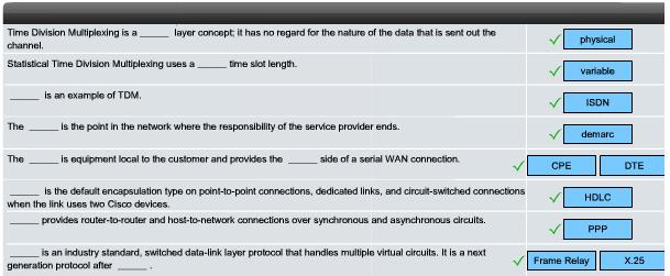
9 Time Division Multiplexing (TDM) TDM divides the bandwidth of a single link into separate channels or time slots. TDM transmits two or more channels over the same link by allocating a different time interval (time slot) for the transmission of each channel. TDM is a physical layer concept. It has no regard of the information that is being multiplexed. The multiplexer (MUX) accepts input from attached devices in a round-robin fashion and transmits the data in a never-ending pattern. The MUX puts each segment into a single channel by inserting each segment into a timeslot. A MUX at the receiving end separate data streams based only on the timing of the arrival of each bit. A technique called bit interleaving keeps track of the sequence of the bits so that they can be efficiently reassembled into their original form upon receipt. 9

10 Statistical Time Division Multiplexing Statistical time-division multiplexing (STDM) was developed to overcome this inefficiency. STDM uses a variable time slot length allowing channels to compete for any free slot space. It employs a buffer memory that temporarily stores the data during periods of peak traffic. STDM does not waste high-speed line time with inactive channels using this scheme. STDM requires each transmission to carry identification information (a channel identifier). 10
 has three channels consisting of two 64 kb/s B-channels (B1 and B2), and a 16 kb/s D- channel. The TDM has nine timeslots, which are repeated in the sequence shown in the figure.")
 x n.")
11 TDM Examples - ISDN and SONET An example of a technology that uses synchronous TDM is ISDN. ISDN basic rate (BRI) has three channels consisting of two 64 kb/s B-channels (B1 and B2), and a 16 kb/s D- channel. The TDM has nine timeslots, which are repeated in the sequence shown in the figure. On a larger scale, the industry uses the SONET or SDH for optical transport of TDM data. SONET, used in North America, and SDH, used elsewhere, for synchronous TDM over fiber. SONET/SDH takes n bit streams, multiplexes them, and optically modulates the signal, sending it out using a light emitting device over fiber with a bit rate equal to (incoming bit rate) x n. Thus traffic arriving at the SONET multiplexer from four places at 2.5 Gb/s goes out as a single stream at 4 x 2.5 Gb/s, or 10 Gb/s. SDH - Synchronous Digital Hierarchy SONET - Synchronous optical networking 11

, and so on.")
12 TDM Examples - T-Carrier Hierarchy DS0: The original unit used in multiplexing telephone calls is 64 kb/s, which represents one phone call. T1: In North America, 24 DS0 units are multiplexed using TDM into a higher bit-rate signal with an aggregate speed of Mb/s for transmission over T1 lines. While it is common to refer to a Mb/s transmission as a T1, it is more correct to refer to it as DS1. T-carrier refers to the bundling of DS0s. A T1 = 24 DSOs, A T1C = 48 DSOs (or 2 T1s), and so on. E1: Outside North America, 32 DS0 units are multiplexed for E1 transmission at Mb/s. 12
 and network service provider equipment.")
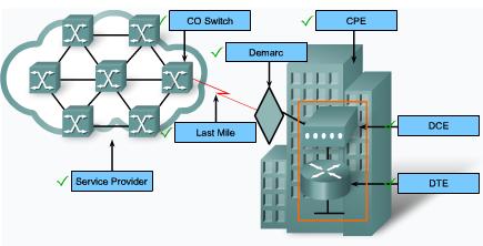
13 Demarcation Point The demarcation point marks the point where your network interfaces with the network owned by another organization. This is the interface between customer-premises equipment (CPE) and network service provider equipment. The demarcation point is the point in the network where the responsibility of the service provider ends. The example presents an ISDN scenario. In the United States, a service provider provides the local loop into the customer premises, The customer provides the active equipment such as the channel service unit/data service unit (CSU/DSU) on which the local loop is terminated. The customer is responsible for maintaining, replacing, or repairing the equipment. In other countries, the network terminating unit (NTU) is provided and managed by the service provider. The customer connects a CPE device, such as a router or frame relay access device, to the NTU using a V.35 or RS-232 serial interface. 13

14 DTE and DCE In order to be connecting to the WAN, a serial connection has a DTE device at one end of the connection and a DCE device at the other end. The DTE, which is generally a router. The DTE could also be a terminal, computer, printer, or fax machine. The DCE, commonly a modem or CSU/DSU, is the device used to convert the user data from the DTE into a form acceptable to the WAN service provider transmission link. This signal is received at the remote DCE, which decodes the signal back into a sequence of bits. The remote DCE then signals this sequence to the remote DTE. The connection between the two DCE devices is the WAN service provider transmission network. Cisco Internal T1 CSU/DSU WIC-1DSU-T1 14

15 DTE and DCE DTE and DCE Cable Standards Originally, the concept of DCEs and DTEs was based on two types of equipment: terminal equipment that generated or received data, and communication equipment that only relayed data. We are left with two different types of cables: one for connecting a DTE to a DCE, another for connecting two DTEs directly to each other. The DTE/DCE interface standard defines the following specifications: Mechanical/physical - Number of pins and connector type Electrical - Defines voltage levels for 0 and 1 Functional - Specifies the functions that are performed by assigning meanings to each of the signaling lines in the interface Procedural - Specifies the sequence for transmitting data The Serial Cables The original RS-232 standard only defined the connection of DTEs with DCEs, which were modems. A null modem is a communication method to directly connect two DTEs, such as a computer, terminal, or printer, using a RS-232 serial cable. With a null modem connection, the transmit (Tx) and receive (Rx) lines are crosslinked. 15


16 DTE and DCE The DB-60 Connector The cable for the DTE to DCE connection is a shielded serial cable. The router end of the serial cable may be a DB-60 connector. The other end of the serial transition cable is available with the connector appropriate for the standard that is to be used. The Smart Serial Connector To support higher port densities in a smaller form factor, Cisco has introduced a Smart Serial cable. The router interface end of the Smart Serial cable is a 26-pin connector that is significantly more compact than the DB-60 connector. The Router-to-Router When using a null modem, keep in mind that synchronous connections require a clock signal. When using a null modem cable in a router-torouter connection, one of the serial interfaces must be configured as the DCE end to provide the clock signal for the connection. 16
 describing the physical interface and protocol for relatively low-speed, serial data communication between computers and related devices.")
17 DTE and DCE: Parallel to Serial Conversion The terms DTE and DCE are relative with respect to what part of a network you are observing. RS-232C is the recommended standard (RS) describing the physical interface and protocol for relatively low-speed, serial data communication between computers and related devices. The DTE is the RS-232C interface that a computer uses to exchange data with a modem or other serial device. The DCE is the RS-232C interface that a modem or other serial device uses in exchanging data with the computer. Your PC also has a Universal Asynchronous Receiver/Transmitter (UART) chip on the motherboard. The UART is the DTE agent of your PC and communicates with the modem or other serial device, which, in accordance with the RS-232C standard, has a complementary interface called the DCE interface. The data in your PC flows along parallel circuits, the UART chip converts the groups of bits in parallel to a serial stream of bits. 17

18 WAN Encapsulation Protocols On WAN connection, data is encapsulated into frames before crossing the WAN link. The protocol depends on the WAN technology and communicating equipment: HDLC - The default encapsulation type on point-to-point connections, when the link uses two Cisco devices. PPP - Provides router-to-router and host-to-network connections over synchronous and asynchronous circuits. PPP works with several network protocols, such as IP and IPX. PPP also has built-in security mechanisms such as PAP and CHAP. Serial Line Internet Protocol (SLIP) - A standard protocol for point-to-point serial connections using TCP/IP. SLIP has been largely displaced by PPP. X.25/Link Access Procedure, Balanced (LAPB) - X.25 specifies LAPB, a data link layer protocol. X.25 is a predecessor to Frame Relay. Frame Relay - Frame Relay eliminates some of the timeconsuming processes (such as error correction and flow control) employed in X.25. ATM - The cell relay in which devices send multiple service types (voice, video, or data) in fixed-length (53-byte) cells. Fixed-length cells allow processing to occur in hardware, thereby reducing transit delays. With SLIP, you have to know the IP address assigned to you by your service provider. You also need to know the IP address of the remote system you will be dialing into. You may also need to configure such details as MTU (maximum transmission unit), MRU (maximum receive unit), etc. 18
19 HDLC Encapsulation HDLC is a bit-oriented synchronous data link layer protocol developed by the International Organization for Standardization (ISO). HDLC was developed from the Synchronous Data Link Control (SDLC) standard proposed in the 1970s. HDLC provides both connection-oriented and connectionless service. HDLC defines a Layer 2 framing structure that allows for flow control and error control through the use of acknowledgments. HDLC uses a frame delimiter, or flag, to mark the beginning and the end of each frame. Cisco has developed an extension to the HLDC protocol to solve the inability to provide multiprotocol support. Cisco HLDC (also referred to as chdlc) is proprietary Cisco HDLC frames contain a field for identifying the network protocol being encapsulated. 19

 frame: S-frames provide control information. Unnumbered (U) frame: U-frames support control purposes and are not sequenced.")
20 HLDC Frame Types Flag - The flag field initiates and terminates error checking. The frame always starts and ends with an 8-bit flag field. The bit pattern is Address - The address field contains the HDLC address of the secondary station. This address can contain a specific address, a group address, or a broadcast address. Control - HDLC defines three types of frames, each with a different control field format: Information (I) frame: I-frames carry upper layer information and some control information. Supervisory (S) frame: S-frames provide control information. Unnumbered (U) frame: U-frames support control purposes and are not sequenced. Protocol - (only in Cisco HDLC) It specifies the protocol type encapsulated within the frame (e.g. 0x0800 for IP). Data - The data field contains a path information unit (PIU) or exchange identification (XID) information. Frame check sequence (FCS) - The FCS precedes the ending flag delimiter and is usually a cyclic redundancy check (CRC) calculation remainder. 20


21 Configuring HDLC Encapsulation Cisco HDLC is the default encapsulation method used by Cisco devices on synchronous serial lines. You use Cisco HDLC as a point-to-point protocol on leased lines between two Cisco devices. If the default encapsulation method has been changed, use the encapsulation hdlc command in privileged mode to re-enable HDLC. If you are connecting to a non-cisco device, use synchronous PPP. There are two steps to enable HDLC encapsulation: Step 1. Enter the interface configuration mode of the serial interface. Step 2. Enter the encapsulation hdlc command to specify the encapsulation protocol on the interface. The output of the show interfaces serial command displays information specific to serial interfaces. When HDLC is configured, "Encapsulation HDLC" 21
22 Troubleshooting a serial interface Show ip int brief (sh ip int b) Router# show ip interface brief Interface IP-Address OK? Method Status Protocol Ethernet YES manual up up Serial YES manual administratively down down Serial x is down, line protocol is down Serial x is up, line protocol is down Serial x is up, line protocol is up (looped) Serial x is up, line protocol is down (disabled) Serial x is administratively down, line protocol is down 22
 Five possible problem states can be identified in the interface status line of the show")
 Serial x is up, line protocol is down")
23 Troubleshooting a serial interface (cont.) Five possible problem states can be identified in the interface status line of the show interfaces serial display: Serial x is down, line protocol is down Serial x is up, line protocol is down Serial x is up, line protocol is up (looped) Serial x is up, line protocol is down (disabled) Serial x is administratively down, line protocol is down 23
 Five possible problem states can be identified in the")

 Serial x is")
24 Troubleshooting a serial interface (cont.) Five possible problem states can be identified in the interface status line of the show interfaces serial display: Serial x is down, line protocol is down Serial x is up, line protocol is down Serial x is up, line protocol is up (looped) Serial x is up, line protocol is down (disabled) Serial x is administratively down, line protocol is down 24

25 Troubleshooting a Serial Interface The show controllers command is another important diagnostic tool when troubleshooting serial lines. In the figure, serial interface 0/0 has a V.35 DCE cable attached. show controllers serial command. If the electrical interface output is shown as UNKNOWN instead of V.35, EIA/TIA-449, or some other electrical interface type, the likely problem is an improperly connected cable. If the electrical interface is unknown, the corresponding display for the show interfaces serial <x> command shows that the interface and line protocol are down. 25

26 Troubleshooting a Serial Interface: Activity 26
27 Troubleshooting a Serial Interface: Activity 27

28 What is PPP? Recall that HDLC is the default serial encapsulation method when you connect two Cisco routers. Cisco HDLC can only work with other Cisco devices. However, when you need to connect to a non-cisco router, you should use PPP encapsulation. PPP includes many features not available in HDLC: The link quality management feature monitors the quality of the link. If too many errors are detected, PPP takes the link down. PPP supports PAP and CHAP authentication. PPP contains three main components: HDLC protocol for encapsulating datagrams over point-to-point links. Extensible Link Control Protocol (LCP) to establish, configure, and test the data link connection. Family of Network Control Protocols (NCPs) for establishing and configuring different network layer protocols. PPP allows the simultaneous use of multiple network layer protocols. Some of the more common NCPs are Internet Protocol Control Protocol, Appletalk Control Protocol, Novell IPX Control Protocol, Cisco Systems Control Protocol, SNA Control Protocol, and Compression Control Protocol. 28

29 PPP Layered Architecture PPP and OSI share the same physical layer, but PPP distributes the functions of LCP and NCP differently. At the physical layer, you can configure PPP on: Asynchronous serial Synchronous serial HSSI ISDN PPP does not impose any restrictions regarding transmission rate other than those imposed by the particular DTE/DCE interface in use. Most of the work done by PPP is at the data link and network layers by the LCP and NCPs. The LCP sets up the PPP connection and its parameters The NCPs handle higher layer protocol configurations, and the LCP terminates the PPP connection. 29

30 PPP Architecture - Link Control Protocol Layer The LCP sits on top of the physical layer and has a role in establishing, configuring, and testing the datalink connection. The LCP establishes the point-to-point link. The LCP also negotiates and sets up control options on the WAN data link, which are handled by the NCPs. The LCP provides automatic configuration of the interfaces at each end, including: Handling varying limits on packet size Detecting common misconfiguration errors Terminating the link Determining when a link is functioning properly or when it is failing PPP also uses the LCP to agree automatically on encapsulation formats (authentication, compression, error detection) as soon as the link is established. 30
, IPX uses the Novell IPX Control Protocol (IPXCP).")

31 PPP Architecture - Network Control Protocol Layer PPP permits multiple network layer protocols to operate on the same communications link. For every network layer protocol used, PPP uses a separate NCP. For example, IP uses the IP Control Protocol (IPCP), IPX uses the Novell IPX Control Protocol (IPXCP). NCPs include functional fields containing standardized codes (PPP protocol field numbers shown in the figure) to indicate the network layer protocol that PPP encapsulates. Each NCP manages the specific needs required by its respective network layer protocols. The various NCP components encapsulate and negotiate options for multiple network layer protocols. 31


32 PPP Frame Structure A PPP frame has six fields as shown in the figure. The LCP can negotiate modifications to the standard PPP frame structure. 32
 The LCP tests the link to determine whether the link quality is sufficient to bring up network layer protocols.")
33 Establishing a PPP Session The three phases of establishing a PPP session: Phase 1: Link establishment and configuration negotiation The LCP must first open the connection and negotiate configuration options. Phase 2: Link quality determination (optional) The LCP tests the link to determine whether the link quality is sufficient to bring up network layer protocols. Phase 3: Network layer protocol configuration negotiation After the LCP has finished the link quality determination phase, the appropriate NCP can separately configure the network layer protocols, and bring them up and take them down at any time. The link remains configured for communications until explicit LCP or NCP frames close the link, or until some external event occurs. This happen because of the loss of the carrier, authentication failure, link quality failure, the expiration of idle-period timer, or administrative closing the link. 33
 During link establishment, the LCP opens the connection and negotiates the configuration parameters.")
34 Establishing a Link with LCP LCP operation uses three classes of LCP frames to accomplish the work of each of the LCP phases: Link-establishment frames establish and configure a link (Configure-Request, Configure-Ack, Configure-Nak, and Configure-Reject) During link establishment, the LCP opens the connection and negotiates the configuration parameters. The Configure-Request frame includes a variable number of configuration options needed to set up on the link. Link-maintenance frames manage and debug a link (Code-Reject, Protocol-Reject, Echo-Request, Echo- Reply, and Discard-Request) Echo-Request, Echo-Reply, and Discard-Request - These frames can be used for testing the link. Link-termination frames terminate a link (Terminate- Request and Terminate-Ack) The link remains open until the LCP terminates it. If the LCP terminates the link before the NCP, the NCP session is also terminated. The device initiating the shutdown sends a Terminate- Request message. The other device replies with a Terminate-Ack. 34


35 LCP Packet Each LCP packet is a single LCP message consisting of Code field identifying the type of LCP packet, The code field of the LCP packet identifies the packet type according to the table. Identifier field so that requests and replies can be matched, Length field indicating the size of the LCP packet Data: Packet type-specific data. 35


36 PPP Configuration Options PPP can be configured to support: Authentication using either PAP or CHAP Compression using either Stacker or Predictor Multilink which combines two or more channels to increase the WAN bandwidth To negotiate the use of these PPP options, the LCP link-establishment frames contain Option information in the Data field of the LCP frame. This phase is complete when a configuration acknowledgment frame has been sent and received. 36

37 NCP Process After the LCP has configured and authenticated the basic link, the appropriate NCP of the network layer protocol being used. There are NCPs for IP, IPX, AppleTalk, and others. IPCP Example After LCP has established the link, the routers exchange IPCP messages, negotiating options specific to the protocol. IPCP negotiates two options: Compression - Allows devices to negotiate an algorithm to compress TCP and IP headers and save bandwidth. IP-Address - Allows the initiating device to specify an IP address to use for routing IP over the PPP link, or to request an IP address for the responder. Dialup network links commonly use the IP address option. When the NCP process is complete, the link goes into the open state and LCP takes over again. 37

38 NCP Explained: Activity 38
 and Challenge Handshake Authentication Protocol (CHAP).")
39 PPP Configuration Options PPP may include the following LCP options: Authentication - Peer exchange authentication messages. Two choices are Password Authentication Protocol (PAP) and Challenge Handshake Authentication Protocol (CHAP). Compression - Increases the effective throughput on PPP connections by reducing the amount of data in the frame that must travel across the link. Two compression are Stacker and Predictor. Error detection - Identifies fault conditions. The Quality and Magic Number options help ensure a reliable, loop-free data link. Multilink - Cisco IOS Release 11.1 and later supports multilink PPP. This alternative provides load balancing over the router interfaces that PPP uses. PPP Callback - To enhance security, Cisco IOS Release 11.1 and later offers callback over PPP. The client makes the initial call, requests that the server call it back, and terminates its initial call. 39
40 PPP Configuration Commands Example 1: Enabling PPP on an Interface To set PPP as the encapsulation method used by a serial or ISDN interface, use the encapsulation ppp interface configuration command. R3#configure terminal R3(config)#interface serial 0/0 R3(config-if)#encapsulation ppp You must first configure the router with an IP routing protocol to use PPP encapsulation. If you do not configure PPP on a Cisco router, the default encapsulation for serial interfaces is HLDC. Example 2: Compression You can configure point-to-point compression on serial interfaces after you have enabled PPP. Because this option invokes a software compression process, it can affect system performance. If the traffic already consists of compressed files (.zip,.tar, or.mpeg, for example), do not use this option. R3(config)#interface serial 0/0 R3(config-if)#encapsulation ppp R3(config-if)#compress [predictor stac] Why? 40
41 PPP Configuration Commands Example 3: Link Quality Monitoring LCP provides an optional link quality determination phase. If the link quality percentage is not maintained, the link is deemed to be of poor quality and is taken down. This example configuration monitors the data dropped on the link and avoids frame looping: R3(config)#interface serial 0/0 R3(config-if)#encapsulation ppp R3(config-if)#ppp quality 80 Example 4: Load Balancing Across Links Multilink PPP (also referred to as MP, MPPP, MLP, or Multilink) provides a method for spreading traffic across multiple physical WAN links while providing packet fragmentation and reassembly, proper sequencing, multivendor interoperability, and load balancing on inbound and outbound traffic. Router(config)#interface serial 0/0 Router(config-if)#encapsulation ppp Router(config-if)#ppp multilink 41

42 Verified a Serial PPP Encapsulation Configuration Use the show interfaces serial command to verify proper configuration of HDLC or PPP encapsulation. When you configure HDLC, the output of the show interfaces serial command should show "encapsulation HDLC". When you configure PPP, you can check its LCP and NCP states. 42

43 Troubleshooting the Serial Encapsulation Configuration Debug displays information about various router operations and the related traffic generated or received by the router, as well as any error messages. It is a very useful and informative tool, but you must always remember that Cisco IOS treats debug as a high priority task. It can consume a significant amount of resources, and the router is forced to processswitch the packets being debugged. Debug must not be used as a monitoring tool-it is meant to be used for a short period of time for troubleshooting. Use the debug ppp command to display information about the operation of PPP. 43
 side of the connection.")
44 Output of the debug ppp packet Command A good command to use when troubleshooting serial interface encapsulation is debug ppp packet. The example in the figure is output from the debug ppp packet command as seen from the Link Quality Monitor (LQM) side of the connection. This display example depicts packet exchanges under normal PPP operation. Look at each line in the output and match it to the meaning of the field. PPP - PPP debugging output. Serial2 - Interface number associated with this debugging information. (o), O - The detected packet is an output packet. (i), I - The detected packet is an input packet. lcp_slqr() - Procedure name; running LQM, send a Link Quality Report (LQR). lcp_rlqr() - Procedure name; running LQM, received an LQR. input (C021) - Router received a packet of the specified packet type (in hexadecimal). A value of C025 indicates packet of type LQM. state = OPEN - PPP state; normal state is OPEN. magic = D21B4 - Magic Number for indicated node; when output is indicated, this is the Magic Number of the node on which debugging is enabled. The actual Magic Number depends on whether the packet detected is indicated as I or O. 44

45 Output of the debug ppp negotiation Command The figure shows the output of the debug ppp negotiation command in a normal negotiation, where both sides agree on network control program (NCP) parameters. In this case, protocol type IP is proposed and acknowledged. The first two lines indicate that the router is trying to bring up the LCP and will use the indicated negotiation options (Quality Protocol and Magic Number). The value fields are the values of the options themselves. C025/3E8 translates to Quality Protocol LQM. 3E8 is the reporting period (in hundredths of a second). 3D56CAC is the value of the Magic Number for the router. ppp: sending CONFREQ, type = 4 (CI_QUALITYTYPE), value = C025/3E8 ppp: sending CONFREQ, type = 5 (CI_MAGICNUMBER), value = 3D56CAC The next two lines indicate that the other side negotiated for options 4 and 5 and that it requested and acknowledged both. If the responding end does not support the options, the responding node sends a CONFREJ. If the responding end does not accept the value of the option, it sends a CONFNAK with the value field modified. ppp: received config for type = 4 (QUALITYTYPE) acked ppp: received config for type = 5 (MAGICNUMBER) value = 3D567F8 acked (ok) 45

46 Output of the debug ppp error Command You can use the debug ppp error command to display protocol errors and error statistics associated with PPP connection negotiation and operation. These messages might appear when the Quality Protocol option is enabled on an interface that is already running PPP. Look at each line in the output and match it to the meaning of the field. PPP - PPP debugging output. Serial3(i) - Interface number associated with this debugging information; indicates that this is an input packet. rlqr receive failure - Receiver does not accept the request to negotiate the Quality Protocol option. myrcvdiffp = Number of packets received over the time period specified. peerxmitdiffp = Number of packets sent by the remote node over this period. myrcvdiffo = Number of octets received over this period. peerxmitdiffo = Number of octets sent by the remote node over this period. threshold = 25 - Maximum error percentage acceptable on this interface. You calculate this percentage using the threshold value entered in the ppp quality percentage interface configuration command. A value of 100 minus number is the maximum error percentage. In this case, a number of 75 was entered. This means that the local router must maintain a minimum 75 percent non-error percentage, or the PPP link closes down. 46

47 PPP Authentication Protocols PPP defines an extensible LCP that allows negotiation of an authentication protocol for authenticating its peer before allowing network layer protocols to transmit over the link. PAP is a very basic two-way process. There is no encryption-the username and password are sent in plain text. If it is accepted, the connection is allowed. CHAP is more secure than PAP. It involves a threeway exchange of a shared secret. The authentication phase of a PPP session is optional. If used, you can authenticate the peer after the LCP establishes the link. If it is used, authentication takes place before the network layer protocol configuration phase begins. The authentication options require that the calling side of the link enter authentication information. This helps to ensure that the user has the permission of the network administrator to make the call. 47


48 Password Authentication Protocol (PAP) PPP can performs Layer 2 authentication in addition to other layers of authentication PAP provides method for a remote node to establish its identity using a two-way handshake. the ppp authentication pap command is used, the remote node repeatedly sends a usernamepassword pair across the link until the sending node acknowledges it or terminates the connection. Using PAP, you send passwords across the link in clear text and there is no protection from playback or repeated trial-and-error attacks. There are times when using PAP is justified. Client applications that do not support CHAP Incompatibilities between different vendor implementations of CHAP Situations where a plaintext password must be available to simulate a login at the remote host 48


49 Challenge Handshake Authentication Protocol (CHAP) Once authentication is established with PAP, it essentially stops working. This leaves the network vulnerable to attack. CHAP conducts periodic challenges to make sure that the remote node still has a valid password value. The password value is variable and changes unpredictably while the link exists. After the PPP link establishment phase is complete, The router sends a challenge to the remote node. The remote node responds with a value calculated using a one-way hash function using MD5. The local router checks the response against its own calculation of the expected hash value. If the values match, the initiating node acknowledges the authentication. Otherwise, it immediately terminates the connection. Because the challenge is unique and random, the resulting hash value is also unique and random. 49

50 PPP Encapsulation and Authentication Process You can use a flowchart to help understand the PPP authentication process when configuring PPP. If an incoming PPP request requires no authentication, then PPP progresses to the next level. If an incoming PPP request requires authentication, then it can be authenticated using either the local database or a security server. Successful authentication progresses to the next level, An authentication failure will disconnect and drop the incoming PPP request. 50

51 PPP Encapsulation and Authentication Process Router R1 wishes to establish an PPP CHAP connection with Router R2. Step 1. R1 negotiates the link connection using LCP with router R2 and the two systems agree to use CHAP authentication during the PPP LCP negotiation. Step 2. Router R2 generates an ID and a random number and its username as a CHAP challenge packet to R1. Step 3. R1 will use the username of the challenger (R2) and cross reference it with its local database to find its associated password. R1 will then generate a unique MD5 hash number using the R2's username, ID, random number and the shared secret password. Step 4. Router R1 then sends the challenge ID, the hashed value, and its username (R1) to R2. 51


52 PPP Encapsulation and Authentication Process Step 5. R2 generates it own hash value using the ID, the shared secret password, and the random number it originally sent to R1. Step 6. R2 compares its hash value with the hash value sent by R1. If the values are the same, R2 sends a link established response to R1. If the authentication failed, a CHAP failure packet is built from the following components: 04 = CHAP failure message type id = copied from the response packet "Authentication failure" or some such text message, which is meant to be a userreadable explanation Note that the shared secret password must be identical on R1 and R2. 52

53 The ppp authentication Command To specify the order in which the CHAP or PAP protocols are requested on the interface, use the ppp authentication interface command. You may enable PAP or CHAP or both. After you have enabled CHAP or PAP authentication, or both, the local router requires the remote device to prove its identity before allowing data traffic to flow. If both methods are enabled, the first method specified is requested during link negotiation. If the peer suggests using the second method or simply refuses the first method, the second method is tried. 53

54 Configuring PPP with Authentication The procedure outlined in the table describes how to configure PPP encapsulation and PAP/CHAP authentication protocols. 54


55 Configuring PPP with Authentication PAP CHAP The figure is an example of a two-way PAP authentication configuration. Both routers authenticate and are authenticated, so the PAP authentication commands mirror each other. [Tony]: The term two-way used here is not the same term used in two-way handshake. This two-way here means R1 challenge R3 and R3 also challenge R1. The PAP username and password that each router sends must match those specified with the username name password password command of the other router. CHAP periodically verifies the identity of the remote node using a three-way handshake. The hostname on one router must match the username the other router has configured. The passwords must also match. This occurs on initial link establishment and can be repeated any time after the link has been established. The router name and password are exactly the same, because they are case-sensitive 55


56 Troubleshooting the serial encapsulation configuration The debug ppp authentication command displays the authentication exchange sequence. Figure illustrates the Left router output during CHAP authentication with the router on the right when debug ppp authentication is enabled. With two-way authentication configured, each router authenticates the other. Messages appear for both the authenticating process and the process of being authenticated. Use the debug ppp authentication command to display the exchange sequence as it occurs. Figure highlights router output for a twoway PAP authentication. The debug ppp command is used to display information about the operation of PPP. The no form of this command disables debugging output. Router#debug ppp {authentication packet negotiation error chap} Router#no debug ppp {authentication packet negotiation error chap} 56
57 One-Way and Two-Way Authentication CHAP is defined as a one-way authentication method. However, you use CHAP in both directions to create a two-way authentication. Hence, with two-way CHAP, a separate three-way handshake is initiated by each side. In the Cisco CHAP implementation, by default, the called party must authenticate the calling party (unless authentication is completely turned off). Therefore, a one-way authentication initiated by the called party is the minimum possible authentication. However, the calling party can also verify the identity of the called party, and this results in a two-way authentication. One-way authentication is often required when you connect to non- Cisco devices. For one-way authentication, configure the ppp authentication chap callin command on the calling router. 57
58 One-Way and Two-Way Authentication If you want to operate with non-cisco routers that do not support authentication by the calling router or device, you must use the ppp authentication chap callin command. When using the ppp authentication command with the callin keyword. the username and password that is allocated by the ISP may not be the remote router's hostname. In such a situation, the ppp chap hostname command is used to specify an alternate username that will be used for authentication. 58
59 One-Way and Two-Way Authentication 59
60 debug ppp negotiation Debug ppp negotiation includes: LCP (Mandatory Phase) Authentication (Optional Phase) (debug ppp authentication) NCP (Mandatory Phase) 60

61 Troubleshooting a PPP Configuration with Authentication Authentication is a feature that needs to be implemented correctly or the security of your serial connection may be compromised. Never assume your authentication configuration works without testing it. Debugging allows you to confirm your configuration and correct any deficiencies. The command is debug ppp authentication. Line 1 says that the router is unable to authenticate on interface Serial0 because the peer did not send a name. Line 2 says the router was unable to validate the CHAP response because USERNAME 'pioneer' was not found. Line 3 says no password was found for 'pioneer'. In the last line, the code = 4 means a failure has occurred. Other code values are as follows: 1 = Challenge 2 = Response 3 = Success 4 = Failure id = 3 is the ID number per LCP packet format. len = 48 is the packet length without the header. 61
62 Chapter Summary In this chapter, you have learned to: Describe the fundamental concepts of point-topoint serial Tony Chen COD communication. Cisco Networking Academy Describe key PPP concepts. Configure PPP encapsulation. Explain and configure PAP and CHAP authentication. 62
Time Division Multiplexing (TDM) Demarcation Point Serial and parallel ports HDLC Encapsulation PPP
 Demarcation Point Serial and parallel ports HDLC Encapsulation PPP") CCNA4 Chapter 2 * Time Division Multiplexing (TDM) TDM divides the bandwidth of a single link into separate channels or time slots. The multiplexer (MUX) accepts input from attached devices in a round-robin
CCNA4 Chapter 2 * Time Division Multiplexing (TDM) TDM divides the bandwidth of a single link into separate channels or time slots. The multiplexer (MUX) accepts input from attached devices in a round-robin
PPP. Point-to-Point Protocol
 PPP Point-to-Point Protocol 1 Introduction One of the most common types of WAN connection is the point-to-point connection. Point-to-point connections are used to connect LANs to service provider WANs,
Overview encapsulation hdlc show interface show controllers show interface debug PPP
 PPP CCNA 4 Overview Explain serial communication Describe and give an example of TDM Identify the demarcation point in a WAN Describe the functions of the DTE and DCE Discuss the development of HDLC encapsulation
PPP Configuration Options
 PPP Configuration Options 1 PPP Configuration Options PPP can be configured to support various functions including: Authentication using either PAP or CHAP Compression using either Stacker or Predictor
6.1. WAN Type. WAN types include the following:
 6.1. WAN Type WAN types include the following: Method Point to Point Circuit Switching Packet Switching Description A point to point connection is a single, pre established path from the customer's network
Point-to-Point Protocol (PPP)
") Point-to-Point Protocol (PPP) Accessing the WAN Chapter 2 Version 4.0 2006 Cisco Systems, Inc. All rights reserved. Cisco Public 1 Objectives Describe the fundamental concepts of point-to-point serial
Point-to-Point Protocol (PPP) Accessing the WAN Chapter 2 Version 4.0 2006 Cisco Systems, Inc. All rights reserved. Cisco Public 1 Objectives Describe the fundamental concepts of point-to-point serial
Point-to-Point Protocol (PPP) Accessing the WAN Chapter 2
 Accessing the WAN Chapter 2") Point-to-Point Protocol (PPP) Accessing the WAN Chapter 2 ITE I Chapter 6 2006 Cisco Systems, Inc. All rights reserved. Cisco Public 1 Objectives Describe the fundamental concepts of point-to-point serial
Point-to-Point Protocol (PPP) Accessing the WAN Chapter 2 ITE I Chapter 6 2006 Cisco Systems, Inc. All rights reserved. Cisco Public 1 Objectives Describe the fundamental concepts of point-to-point serial
Implementing Enterprise WAN Links
 Implementing Enterprise WAN Links Introducing Routing and Switching in the Enterprise Chapter 7 Version 4.0 1 Objectives Describe the features and benefits of common WAN connectivity options. Compare and
15 WAN Introduction CERTIFICATION OBJECTIVES Q&A Wide Area Networking Overview HDLCp PPP. Two-Minute Drill Self Test
 15 WAN Introduction CERTIFICATION OBJECTIVES 15.01 Wide Area Networking Overview 15.02 HDLCp 15.03 PPP Q&A Two-Minute Drill Self Test 2 Chapter 15: WAN Introduction The last few chapters introduced you
CCNA 4 - Final Exam (A)
") CCNA 4 - Final Exam (A) 1. A network administrator is asked to design a system to allow simultaneous access to the Internet for 250 users. The ISP for this network can only supply five public IPs. What
CCNA 4 - Final Exam (A) 1. A network administrator is asked to design a system to allow simultaneous access to the Internet for 250 users. The ISP for this network can only supply five public IPs. What
Configuring Dial-on-Demand Routing
 C H A P T E R 7 Configuring Dial-on-Demand Routing This chapter describes how to configure your communication server for dial-on-demand routing (DDR) and dial backup. For a complete description of the
Point-to-Point Protocol (PPP)
") Point-to-Point Protocol (PPP) www.ine.com PPP» Point-to-Point Protocol» Open standard» Operates in the LLC sub-layer of data link layer in OSI» Originally designed for dial-up connections (modems, ISDN,
Point-to-Point Protocol (PPP) www.ine.com PPP» Point-to-Point Protocol» Open standard» Operates in the LLC sub-layer of data link layer in OSI» Originally designed for dial-up connections (modems, ISDN,
Understanding and Troubleshooting Idle Timeouts
 Understanding and Troubleshooting Idle Timeouts Document ID: 23423 Contents Introduction Prerequisites Requirements Components Used Conventions Common Problems and Symptoms Idle Timeouts Interesting Traffic
HDLC (High level Data Link Control)
") High-level Data Link Control HDLC (High level Data Link Control) Modem, EIA-232, HDLC Framing and Procedures Agenda Line Management, Modems Introduction HDLC Station Types, Modes of Operation Frame Format,
High-level Data Link Control HDLC (High level Data Link Control) Modem, EIA-232, HDLC Framing and Procedures Agenda Line Management, Modems Introduction HDLC Station Types, Modes of Operation Frame Format,
Line Protocol Basics. HDLC (High level Data Link Control) Agenda. Additional Issues
 Agenda. Additional Issues") Line Protocol Basics High-level Data Link Control HDLC (High level Data Link Control), EIA-232, HDLC Framing and Procedures line protocol basics already explained serial transmission techniques bit-synchronization
Line Protocol Basics High-level Data Link Control HDLC (High level Data Link Control), EIA-232, HDLC Framing and Procedures line protocol basics already explained serial transmission techniques bit-synchronization
Lecture (08) Fundamentals of WANs (II)
 Fundamentals of WANs (II)") Agenda Lecture (08) Fundamentals of WANs (II) OSI Layer 2 of WANs ATM & SONET WAN Dr. Ahmed M. ElShafee ١ ٢ OSI Layer 2 of WANs OSI Layer 2 of WANs (2) WAN protocols used on point to point serial links
Agenda Lecture (08) Fundamentals of WANs (II) OSI Layer 2 of WANs ATM & SONET WAN Dr. Ahmed M. ElShafee ١ ٢ OSI Layer 2 of WANs OSI Layer 2 of WANs (2) WAN protocols used on point to point serial links
WAN Technologies CCNA 4
 WAN Technologies CCNA 4 Overview Note: Most of this will be described in more detail in later chapters. Differentiate between a LAN and WAN Identify the devices used in a WAN List WAN standards Describe
Using an ADTRAN Terminal Adapter with Cisco Routers
 Using an ADTRAN Terminal Adapter with Cisco Routers Document ID: 28080 Contents Introduction Prerequisites Requirements Components Used Conventions Dialing Method V.25 or V.25bis Dialing DTR Dialing Keypad
Network Working Group
 Network Working Group Request for Comments: 2637 Category: Informational K. Hamzeh Ascend Communications G. Pall Microsoft Corporation W. Verthein 3Com J. Taarud Copper Mountain Networks W. Little ECI
Configuring Legacy DDR Hubs
 Configuring Legacy DDR Hubs This chapter describes how to configure legacy dial-on-demand routing (DDR) on interfaces functioning as the hub in a hub-and-spoke network topology. It includes the following
Data Link Protocols. TCP/IP Suite and OSI Reference Model
 Data Link Protocols Relates to Lab. This module covers data link layer issues, such as local area networks (LANs) and point-to-point links, Ethernet, and the Point-to-Point Protocol (PPP). 1 TCP/IP Suite
Flow control: Ensuring the source sending frames does not overflow the receiver
 Layer 2 Technologies Layer 2: final level of encapsulation of data before transmission over a physical link responsible for reliable transfer of frames between hosts, hop by hop, i.e. on a per link basis
POINT TO POINT DATALINK PROTOCOLS. ETI 2506 Telecommunication Systems Monday, 7 November 2016
 POINT TO POINT DATALINK PROTOCOLS ETI 2506 Telecommunication Systems Monday, 7 November 2016 TELECOMMUNICATION SYLLABUS Principles of Telecom (IP Telephony and IP TV) - Key Issues to remember PPP Frame
Configuring X.25 on ISDN Using AO/DI
 Configuring X.25 on ISDN Using AO/DI The chapter describes how to configure the X.25 on ISDN using the Always On/Dynamic ISDN (AO/DI) feature. It includes the following main sections: AO/DI Overview How
Ethereal Exercise 2 (Part A): Link Control Protocol
: Link Control Protocol") Course: Semester: ELE437 Ethereal Exercise 2 (Part A): Link Control Protocol Introduction In this exercise some details at the data link layer will be examined. In particular, the Link Control Protocol
Course: Semester: ELE437 Ethereal Exercise 2 (Part A): Link Control Protocol Introduction In this exercise some details at the data link layer will be examined. In particular, the Link Control Protocol
Cisco - Connecting Routers Back-to-Back Through the AUX Ports using a Rollover Cable
 1 of 5 6/12/2001 1:43 PM Connecting Routers Back-to-Back Through the AUX Ports using a Rollover Cable Contents Introduction Conventions Network Diagram Configurations Troubleshooting the Configuration
Chapter 11 Data Link Control 11.1
 Chapter 11 Data Link Control 11.1 Copyright The McGraw-Hill Companies, Inc. Permission required for reproduction or display. 11-1 FRAMING The data link layer needs to pack bits into frames, so that each
Ethereal Exercise 2 (Part B): Link Control Protocol
: Link Control Protocol") Course: Semester: ELE437 Introduction Ethereal Exercise 2 (Part B): Link Control Protocol In this half of Exercise 2, you will look through a more complete capture of a dial-up connection being established.
Course: Semester: ELE437 Introduction Ethereal Exercise 2 (Part B): Link Control Protocol In this half of Exercise 2, you will look through a more complete capture of a dial-up connection being established.
Increasing Bandwidth. Contents
 2 Increasing Bandwidth Contents Overview...................................................... 2-2 Configuring MLPPP............................................. 2-4 PPP.......................................................
CCNA Exploration1 Chapter 7: OSI Data Link Layer
 CCNA Exploration1 Chapter 7: OSI Data Link Layer LOCAL CISCO ACADEMY ELSYS TU INSTRUCTOR: STELA STEFANOVA 1 Explain the role of Data Link layer protocols in data transmission; Objectives Describe how the
Configuring and Troubleshooting Dialer Profiles
 Configuring and Troubleshooting Dialer Profiles Document ID: 10219 Contents Introduction Prerequisites Requirements Components Used Conventions Background Information Are Dialer Profiles Right for You?
1- and 2-Port V.90 Modem WICs for Cisco 2600 and Cisco 3600 Series Multiservice Platforms
 1- and 2-Port V.90 Modem WICs for Cisco 2600 and Cisco 3600 Series Multiservice Platforms Feature History Release 12.2(2)XB Description This feature was introduced. The 1- and 2-port V.90 modem WAN interface
Number of seconds that elapse after the primary line goes down before the router activates the secondary line. The default is 0 seconds.
 This chapter describes the function and displays the syntax of each dialon-demand routing command. For more information about defaults and usage guidelines, see the corresponding chapter of the Router
DDR Routing Commands
 DDR Routing Commands This section describes the function and displays the syntax of each dial-on-demand routing (DDR) command. For more information about defaults and usage guidelines, see the corresponding
Debugging a Virtual Access Service Managed Gateway
 Debugging a Virtual Access Service Managed Gateway Issue: 1.0 Date: 09 July 2013 Table of Contents 1 About this document... 3 1.1 Scope... 3 2 WAN connectivity... 4 2.1 ADSL... 4 2.1.1 Active data connections...
Other Protocols. Arash Habibi Lashkari
 LAN Technology Other Protocols Arash Habibi Lashkari PHD of Computer Science - Information Security July 2010 Other Protocols Outlines: FDDI: Fiber Distributed Data Interface Token Ring: IEEE 802.5 LAN
William Stallings Data and Computer Communications. Chapter 7 Data Link Control
 William Stallings Data and Computer Communications Chapter 7 Data Link Control Flow Control Ensuring the sending entity does not overwhelm the receiving entity Preventing buffer overflow Transmission time
CCNA 4 - Final Exam Answers
 CCNA 4 - Final Exam Answers 1 Which of the following describes the roles of devices in a WAN? (Choose three.) *** A CSU/DSU terminates a digital local loop. A modem terminates a digital local loop. A CSU/DSU
Advanced Computer Networks. Rab Nawaz Jadoon DCS. Assistant Professor COMSATS University, Lahore Pakistan. Department of Computer Science
 Advanced Computer Networks Rab Nawaz Jadoon Department of Computer Science DCS COMSATS Institute of Information Technology Assistant Professor COMSATS University, Lahore Pakistan Advanced Computer Networks
Request for Comments: 1333 May 1992
 Network Working Group Request for Comments: 1333 W. Simpson Daydreamer May 1992 PPP Link Quality Monitoring Status of this Memo This RFC specifies an IAB standards track protocol for the Internet community,
Configuring Modem Transport Support for VoIP
 Configuring Modem Transport Support for VoIP This chapter explains how to configure modem transport support for Voice over IP (VoIP) and contains the following sections: Modem Transport Support Overview,
PPP over Frame Relay
 The feature allows a router to establish end-to-end Point-to-Point Protocol (PPP) sessions over Frame Relay. Finding Feature Information, page 1 Prerequisites for, page 1 Restrictions for, page 2 Information
Terminal Services Commands translate lat
 translate lat translate lat To translate a connection request to another protocol connection type when receiving a local-area transport (LAT) request, use the translate lat command in global configuration
SLIP and PPP Configuration Commands
 CHAPTER 15 SLIP and PPP Configuration Commands SLIP and PPP define methods of sending Internet Protocol (IP) packets over standard EIA/TIA-232 asynchronous serial lines with minimum line speeds of 1200
Part 5: Link Layer Technologies. CSE 3461: Introduction to Computer Networking Reading: Chapter 5, Kurose and Ross
 Part 5: Link Layer Technologies CSE 3461: Introduction to Computer Networking Reading: Chapter 5, Kurose and Ross 1 Outline PPP ATM X.25 Frame Relay 2 Point to Point Data Link Control One sender, one receiver,
WAN technology which are to be discussed:
 WAN Technology Operates at 3 layer OSI model as below: 1. PHY 2. Data Link 3. Network Most of WAN technology are packetswitched network categorized as Switched Virtual circuit Network ( 3-phase, connection
Chapter 11 Data Link Control 11.1
 Chapter 11 Data Link Control 11.1 Copyright The McGraw-Hill Companies, Inc. Permission required for reproduction or display. 11-1 1 FRAMING The data link layer needs to pack bits into frames,, so that
Teldat Router. PPP Interface
 Teldat Router PPP Interface Doc. DM710-I Rev. 10.11 December, 2003 INDEX Chapter 1 PPP Interface...1 1. Description...2 2. PPP Frame structure...3 2.1. Asynchronous PPP adaptation...3 3. Link Control Protocol...5
Configuring Serial Interfaces on the Cisco ASR 9000 Series Router
 Configuring Serial Interfaces on the Cisco ASR 9000 Series Router This module describes the configuration of serial interfaces on the Cisco ASR 9000 Series Router. Feature Histy f Configuring Serial Controller
Virtual Private Networks (VPNs)
") CHAPTER 19 Virtual Private Networks (VPNs) Virtual private network is defined as customer connectivity deployed on a shared infrastructure with the same policies as a private network. The shared infrastructure
CHAPTER 19 Virtual Private Networks (VPNs) Virtual private network is defined as customer connectivity deployed on a shared infrastructure with the same policies as a private network. The shared infrastructure
Vendor-Proprietary Attribute
 RADIUS s The IETF draft standard for RADIUS specifies a method for communicating vendor-proprietary information between the network access server and the RADIUS server. However, some vendors have extended
Module 3. Wide Area Networking (WAN)
") Module 3 Wide Area Networking (WAN) When many nodes or LAN s are connected together in a large scale, we have a WAN. This may be world wide. Because of the separation of the nodes, the Public Data Network
Module 3 Wide Area Networking (WAN) When many nodes or LAN s are connected together in a large scale, we have a WAN. This may be world wide. Because of the separation of the nodes, the Public Data Network
Lecture 1.1: Point to Point Protocol (PPP) An introduction
 An introduction") Lecture 1.1: Point to Point Protocol (PPP) An introduction "the watchword for a point-to-point protocol should be simplicity" (RFC 1547, PPP requirements). disattended by 50+ RFCs Recommended reading:
Lecture 1.1: Point to Point Protocol (PPP) An introduction "the watchword for a point-to-point protocol should be simplicity" (RFC 1547, PPP requirements). disattended by 50+ RFCs Recommended reading:
HP MSR Router Series. Layer 2 - WAN Access Configuration Guide(V7)
") HP MSR Router Series Layer 2 - WAN Access Configuration Guide(V7) Part number: 5998-7721b Software version: CMW710-R0304 Document version: 6PW104-20150914 Legal and notice information Copyright 2015 Hewlett-Packard
HP MSR Router Series Layer 2 - WAN Access Configuration Guide(V7) Part number: 5998-7721b Software version: CMW710-R0304 Document version: 6PW104-20150914 Legal and notice information Copyright 2015 Hewlett-Packard
Network Working Group Request for Comments: 1663 Category: Standards Track July 1994
 Network Working Group D. Rand Request for Comments: 1663 Novell Category: Standards Track July 1994 Status of this Memo PPP Reliable Transmission This document specifies an Internet standards track protocol
Service Managed Gateway TM. Configuring a V90 Modem on an SMG
 Service Managed Gateway TM Configuring a V90 Modem on an SMG Issue 2.1 Date 18 August 2010 Table of contents 1 About this document... 3 1.1 Scope... 3 1.2 Readership... 3 1.3 More information... 3 1.3.1
Configuring Virtual Asynchronous Traffic over ISDN
 Configuring Virtual Asynchronous Traffic over ISDN Cisco IOS software offers two solutions to send virtual asynchronous traffic over ISDN: Using International Telecommunication Union Telecommunication
Networking interview questions
 Networking interview questions What is LAN? LAN is a computer network that spans a relatively small area. Most LANs are confined to a single building or group of buildings. However, one LAN can be connected
HPE FlexNetwork MSR Router Series
 HPE FlexNetwork MSR Router Series Comware 7 Layer 2 - WAN Access Configuration Guides Part number: 5998-8783 Software version: CMW710-E0407 Document version: 6W100-20160526 Copyright 2016 Hewlett Packard
Configuring the Cisco 3825 Mobile Wireless Edge Router in a RAN-O Solution with the Command-Line Interface
 CHAPTER 4 Configuring the Cisco 3825 Mobile Wireless Edge Router in a RAN-O Solution with the Command-Line Interface This chapter describes how to use the Cisco IOS software CLI to configure the Cisco
Configuring Virtual Profiles
 Configuring Virtual Profiles This chapter describes how to configure virtual profiles for use with virtual access interfaces. It includes the following main sections: Virtual Profiles Overview How Virtual
Service Managed Gateway TM. Configuring Dual ADSL PPP with Worker Standby or Load Share Mode
 Service Managed Gateway TM Configuring Dual ADSL PPP with Worker Standby or Load Share Mode Issue 1.3 Date 15 November 2011 Table of contents 1 Introduction... 3 1.1 Scope... 3 1.2 Readership... 3 1.3
Access Server Dial In IP/PPP Configuration With Dedicated V.120 PPP
 Access Server Dial In IP/PPP Configuration With Dedicated V.120 PPP Document ID: 6306 Contents Introduction Prerequisites Requirements Components Used Conventions Background Information How V.120 Affects
Lecture (06) Network Access layer fundamentals (4) LAN, & WAN Internetwork Layer I
 Network Access layer fundamentals (4) LAN, & WAN Internetwork Layer I") Lecture (06) Network Access layer fundamentals (4) LAN, & WAN Internetwork Layer I By: Dr. Ahmed ElShafee ١ Agenda OSI Layer 2 of WANs Internetwork layer Introduction Network Layer Interaction with the
Lecture (06) Network Access layer fundamentals (4) LAN, & WAN Internetwork Layer I By: Dr. Ahmed ElShafee ١ Agenda OSI Layer 2 of WANs Internetwork layer Introduction Network Layer Interaction with the
HP MSR Router Series. Layer 2 - WAN Access Configuration Guide(V7)
") HP MSR Router Series Layer 2 - WAN Access Configuration Guide(V7) Part number: 5998-6465 Software version: CMW710-R0106 Document version: 6PW101-20140807 Legal and notice information Copyright 2014 Hewlett-Packard
HP MSR Router Series Layer 2 - WAN Access Configuration Guide(V7) Part number: 5998-6465 Software version: CMW710-R0106 Document version: 6PW101-20140807 Legal and notice information Copyright 2014 Hewlett-Packard
IP and Network Technologies. IP over WAN. Agenda. Agenda
 IP and Network Technologies IP over WAN Address Resolution, Encapsulation, Routing, NBMA PPP, Inverse ARP, Overview IP over ATM for transport of IP datagrams over a network encapsulation and address resolution
L2TP Configuration. L2TP Overview. Introduction. Typical L2TP Networking Application
 Table of Contents L2TP Configuration 1 L2TP Overview 1 Introduction 1 Typical L2TP Networking Application 1 Basic Concepts of L2TP 2 L2TP Tunneling Modes and Tunnel Establishment Process 4 L2TP Features
Concept Questions Demonstrate your knowledge of these concepts by answering the following questions in the space provided.
 123 Chapter 10 WANs and Routers One major characteristic of a wide-area network (WAN) is that the network operates beyond the local LAN's geographic scope. It uses the services of carriers, such as regional
Using Serial Ports to Connect to ATM with DXI Encapsulation
 Using Serial Ports to Connect to ATM with DXI Encapsulation Document ID: 10418 Contents Introduction Prerequisites Requirements Components Used Conventions Physical Setup ATM DXI Modes ATM DXI Headers
Configuring IP Services
 CHAPTER 8 Configuring IP Services This chapter describes how to configure optional IP services supported by the Cisco Optical Networking System (ONS) 15304. For a complete description of the commands in
Chapter 10 Security Protocols of the Data Link Layer
 Chapter 10 Security Protocols of the Data Link Layer IEEE 802.1x Point-to-Point Protocol (PPP) Point-to-Point Tunneling Protocol (PPTP) [NetSec], WS 2005/06 10.1 Scope of Link Layer Security Protocols
Data Link Layer. Overview. Links. Shivkumar Kalyanaraman
 Data Link Layer shivkuma@ecse.rpi.edu http://www.ecse.rpi.edu/homepages/shivkuma 1-1 Based in part upon the slides of Prof. Raj Jain (OSU) Overview The data link layer problem Error detection and correction
Circuit Emulation over IP
 (CEoIP) provides a virtual circuit through an IP network--similar to a leased line--to integrate solutions that require a time-sensitive, bit-transparent transport into IP networks. Data, with proprietary
Chapter 2 - Part 1. The TCP/IP Protocol: The Language of the Internet
 Chapter 2 - Part 1 The TCP/IP Protocol: The Language of the Internet Protocols A protocol is a language or set of rules that two or more computers use to communicate 2 Protocol Analogy: Phone Call Parties
Data-link. Examples of protocols. Generating polynomials. Example. Error detection in TCP/IP. Multiple Access Links and Protocols
 Computer Networking Data-link layer Prof. Andrzej Duda duda@imag.fr http://duda.imag.fr Data Link Layer Our goals: Understand principles behind link layer services: sharing a broadcast channel: multiple
Accessing the WAN Chapter 1 Modified by Tony Chen 07/20/2008
 Introduction to WANs Accessing the WAN Chapter 1 Modified by Tony Chen 07/20/2008 ITE I Chapter 6 2006 Cisco Systems, Inc. All rights reserved. Cisco Public 1 Notes: If you see any mistake on my PowerPoint
Cisco Cisco Certified Network Associate (CCNA)
") Cisco 200-125 Cisco Certified Network Associate (CCNA) http://killexams.com/pass4sure/exam-detail/200-125 Question: 769 Refer to exhibit: Which destination addresses will be used by Host A to send data
Cisco 200-125 Cisco Certified Network Associate (CCNA) http://killexams.com/pass4sure/exam-detail/200-125 Question: 769 Refer to exhibit: Which destination addresses will be used by Host A to send data
15. PPP and Frame relay in small network
 Published on cdesigner.eu (https://cdesigner.eu) Home > Networks > 15. PPP and Frame relay in small network 15. PPP and Frame relay in small network PPP and Frame relay are protocols operating at data
Data link layer functions. 2 Computer Networks Data Communications. Framing (1) Framing (2) Parity Checking (1) Error Detection
 Framing (2) Parity Checking (1) Error Detection") 2 Computer Networks Data Communications Part 6 Data Link Control Data link layer functions Framing Needed to synchronise TX and RX Account for all bits sent Error control Detect and correct errors Flow
2 Computer Networks Data Communications Part 6 Data Link Control Data link layer functions Framing Needed to synchronise TX and RX Account for all bits sent Error control Detect and correct errors Flow
thus, the newly created attribute is accepted if the user accepts attribute 26.
 Remote Authentication Dial-In User Service (RADIUS) attributes are used to define specific authentication, authorization, and accounting (AAA) elements in a user profile, which is stored on the RADIUS
RADIUS Vendor-Proprietary Attributes
 RADIUS Vendor-Proprietary Attributes Last Updated: January 17, 2012 The IETF draft standard for RADIUS specifies a method for communicating vendor-proprietary information between the network access server
The router sends hello keepalive packets at 60 second intervals.
 hello hello To configure the interval used to exchange hello keepalive packets in a Layer 2 control channel, use the hello command in L2TP class configuration mode. To disable the sending of hello keepalive
Priority list number you specified in the sap-priority-list command.
 sap-priority sap-priority To define a priority list on an interface, use the sap-priority command in interface configuration mode. To remove a priority list on an interface, use the no form of this command.
Configuring a GSM (3G) modem on a GW2040 Series Router
 modem on a GW2040 Series Router") Configuring a GSM (3G) modem on a GW2040 Series Router Issue 1.5 Date 10 May 2012 Table of contents 1 About this document... 3 1.1 Scope... 3 1.2 Readership... 3 1.3 More information... 3 1.3.1 Assigned
Configuring a GSM (3G) modem on a GW2040 Series Router Issue 1.5 Date 10 May 2012 Table of contents 1 About this document... 3 1.1 Scope... 3 1.2 Readership... 3 1.3 More information... 3 1.3.1 Assigned
RADIUS Attributes. RADIUS IETF Attributes
 Remote Authentication Dial-In User Service (RADIUS) attributes are used to define specific authentication, authorization, and accounting (AAA) elements in a user profile, which is stored on the RADIUS
frame-relay lapf n201
 frame-relay lapf n201 frame-relay lapf n201 To set the Link Access Procedure for Frame Relay (LAPF) N201 value (the maximum length of the Information field of the LAPF I frame), use the frame-relay lapf
Chapter 7: Data Link Control. CS420/520 Axel Krings Page 1
 Chapter 7: Data Link Control CS420/520 Axel Krings Page 1 Data Link Control Protocols Need layer of logic above Physical to manage exchange of data over a link frame synchronization flow control error
Chapter 7: Data Link Control. Data Link Control Protocols
 Chapter 7: Data Link Control CS420/520 Axel Krings Page 1 Data Link Control Protocols Need layer of logic above Physical to manage exchange of data over a link frame synchronization flow control error
CCNA 4 - Final Exam (B)
") CCNA 4 - Final Exam (B) 1. Identify the factors that contribute to congestion on an Ethernet LAN. (Choose three.) improper placement of enterprise level servers addition of hosts to a physical segment
CCNA 4 - Final Exam (B) 1. Identify the factors that contribute to congestion on an Ethernet LAN. (Choose three.) improper placement of enterprise level servers addition of hosts to a physical segment
Troubleshooting Frame Relay Connections
 CHAPTER 18 Frame Relay was originally conceived as a protocol for use over ISDN interfaces. Initial proposals to this effect were submitted to the International Telecommunication Union Telecommunication
thus, the newly created attribute is accepted if the user accepts attribute 26.
 Remote Authentication Dial-In User Service (RADIUS) attributes are used to define specific authentication, authorization, and accounting (AAA) elements in a user profile, which is stored on the RADIUS
ELC 537 Communication Networks
 Modern Academy for Engineering and Technology Electronics Engineering and Communication Technology Dpt. ELC 537 Communication Networks Prepared by: Dr. Nelly Muhammad Hussein Sections & Objectives Principles
Chapter 3. The Data Link Layer
 Chapter 3 The Data Link Layer 1 Data Link Layer Algorithms for achieving reliable, efficient communication between two adjacent machines. Adjacent means two machines are physically connected by a communication
Integrated Services Digital Network
 CHAPTER 12 Chapter Goals Explain what ISDN is. Describe ISDN devices and how they operate. Describe the specifications for ISDN data transmittal for the three layers at which ISDN transmits. Introduction
Configuring the 4-Port Serial Interface SPA
 This chapter provides information about configuring the 4-Port Serial Interface SPA on Cisco ASR 1000 Series Routers. Configuration Tasks, page 1 Verifying the Interface Configuration, page 11 Configuration
Configuration of Synchronous Protocols
 encor! enetworks TM Version A, September 2010 2013 Encore Networks, Inc. All rights reserved. Configuration of Synchronous Protocols This chapter discusses synchronous protocols that you can configure
Introduction to Open System Interconnection Reference Model
 Chapter 5 Introduction to OSI Reference Model 1 Chapter 5 Introduction to Open System Interconnection Reference Model Introduction The Open Systems Interconnection (OSI) model is a reference tool for understanding
Configuring BACP. Cisco IOS Dial Technologies Configuration Guide DC-667
 This chapter describes how to configure the Bandwidth Allocation Control Protocol (BACP), described in RFC 2125. It includes the following main sections: BACP Overview How to Configure BACP Monitoring
HP VSR1000 Virtual Services Router
 HP VSR1000 Virtual Services Router Layer 2 - WAN Access Configuration Guide Part number: 5998-6023 Software version: VSR1000_HP-CMW710-R0202-X64 Document version: 6W100-20140418 Legal and notice information
Fragmenting and Interleaving Real-Time and Nonreal-Time Packets
 CHAPTER 16 Fragmenting and Interleaving Real-Time and Nonreal-Time Packets Integrating delay-sensitive real-time traffic with nonreal-time data packets on low-speed links can cause the real-time packets