High Availability (AP SSO) Deployment Guide
|
|
|
- Cory Byrd
- 6 years ago
- Views:
Transcription
1 High Availability (AP SSO) Deployment Guide Document ID: Contents Introduction Prerequisites Requirements Components Used Conventions Topology New HA Overview HA Connectivity Using Redundant Port on the 5500/7500/8500 WLC High Availability Connectivity Using Redundant VLAN on WiSM 2 WLC Introduction of New Interfaces for HA Interaction Configure HA from the CLI Configure HA from the GUI Configure HA from the Configuration Wizard Configure HA from NCS Upgrade the WLC in HA Setup Upgrade Procedure in HA Setup Important Guidelines before Initiating a WLC Upgrade in HA Setup Download/Upload Facts in HA Setup Failover Process in the HA Setup Steps to Simulate Box Failover HA Facts Maintenance Mode AP SSO Deployment with Legacy Primary/Secondary/Tertiary HA AP SSO Deployment in Mobility Setup Licensing for HA Pair One WLC has a valid AP Count license and the other WLC has a HA SKU UDI Both the WLCs have a valid AP Count license One WLC has an Evaluation license and the other WLC has a HA SKU UDI or Permanent license Glossary Related Information Introduction This document provides information on the theory of operation and configuration for the Cisco Unified Wireless LAN Controller (WLC) as it pertains to supporting stateful switchover of access points (AP SSO). The new High Availability (HA) feature (that is, AP SSO) set within the Cisco Unified Wireless Network software release version 7.3 allows the access point (AP) to establish a CAPWAP tunnel with the Active WLC and share a mirror copy of the AP database with the Standby WLC. The APs do not go into the Discovery state when the Active WLC fails and the Standby WLC takes over the network as the Active WLC. There is only one CAPWAP tunnel maintained at a time between the APs and the WLC that is in an Active state. The overall goal for the addition of AP SSO support to the Cisco Unified Wireless LAN was to reduce major downtime in wireless networks due to failure conditions that may occur due to box failover or network failover.

2 Prerequisites Requirements There are no specific requirements for this document. Components Used The information in this document is based on these software and hardware versions: WLCs 5500 Series, 7500/8500 Series, and WiSM 2 APs 1130, 1240, 1250, 1040, 1140, 1260, 2600, 3500, 3600 Series APs, and 1520 or 1550 Series Mesh APs (MAPs) The information in this document was created from the devices in a specific lab environment. All of the devices used in this document started with a cleared (default) configuration. If your network is live, make sure that you understand the potential impact of any command. Conventions Refer to Cisco Technical Tips Conventions for more information on document conventions. Topology This document uses this network topology.

3 New HA Overview The new architecture for HA is for box to box redundancy. In other words, 1:1 where one WLC will be in an Active state and the second WLC will be in a Hot Standby state continuously monitoring the health of the Active WLC via a Redundant Port. Both the WLCs will share the same set of configurations including the IP address of the Management interface. The WLC in the Standby state does not need to be configured independently as the entire configuration (Bulk Configuration while boot up and Incremental Configuration in runtime) will be synched from the Active WLC to the Standby WLC via a Redundant Port. The AP's CAPWAP State (only APs which are in a run state) is also synched, and a mirror copy of the AP database is maintained on the Standby WLC. The APs do not go into the Discovery state when the Active WLC fails and the Standby WLC takes over the network's Active WLC. There is no preempt functionality. When the previous Active WLC comes back, it will not take the role of the Active WLC, but will negotiate its state with the current Active WLC and transition to a Standby state. The Active and Standby decision is not an automated election process. The Active/Standby WLC is decided based on HA SKU (Manufacturing Ordered UDI) from release 7.3 onwards. A WLC with HA SKU UDI will always be the Standby WLC for the first time when it boots and pairs up with a WLC running a permanent count license. For existing WLCs having a permanent count license, the Active/Standby decision can be made based on manual configuration. AP SSO is supported on 5500/7500/8500 and WiSM 2 WLCs. Release 7.3 only supports AP SSO that will ensure that the AP sessions are intact after switchover. The Client SSO is not supported, which means all the clients with an exception of clients on WLANs configured for local switching on Flex APs will be de authenticated and forced to rejoin a new Active WLC. MAPs, which are treated as mesh clients on RAP, are not de authenticated with AP SSO. HA Connectivity Using Redundant Port on the 5500/7500/8500 WLC 5500/7500/8500 WLCs have a dedicated Redundancy Port which should be connected back to back in order to synchronize the configuration from the Active to the Standby WLC. Keepalive packets are sent on the Redundancy Port from the Standby to the Active WLC every 100 msec (default timer) in order to check the health of the Active WLC. Both the WLCs in HA setup keep track of gateway reachability. The Active WLC sends an Internet Control Message Protocol (ICMP) ping to the gateway using the Management IP address as the source, and the Standby WLC sends an ICMP ping to the gateway using the Redundancy Management IP address. Both the WLCs send an ICMP ping to the gateway at a one second interval. It is highly recommended to have back to back direct connectivity between Redundant Ports. Here you can see the Redundant Port Connectivity between 5500 WLCs in an HA Setup: Here you can see the Redundant Port Connectivity between Flex 7500 WLCs in an HA setup:


4 Note: A direct physical connection between Active and Standby Redundant Ports is highly recommended. The distance between the connections can go up to 100 meters at per ethernet cable standards. High Availability Connectivity Using Redundant VLAN on WiSM 2 WLC WiSM 2 WLCs have a dedicated Redundancy VLAN which is used to synchronize the configuration from the Active WLC to the Standby WLC. A Redundancy VLAN should be a Layer 2 VLAN dedicated for the HA Pairing process. It should not be spanned across networks and should not have any Layer 3 SVI interface. No data VLAN should be used as a Redundancy VLAN. Keep alive packets are sent on Redundancy VLAN from the Standby WLC to the Active WLC every 100 msec (default timer) in order to check the health of the Active WLC. Both the WiSMs in a HA setup keep track of gateway reachability. Active WLC sends an ICMP ping to the gateway using the Management IP address as the source, and the Standby WLC sends an ICMP ping to the gateway using the Redundancy Management IP address. Both the WLCs send an ICMP ping to the gateway at a one second interval. In order to achieve HA, WiSM 2 WLCs should only be deployed in a single chassis or deployed between multiple Catalyst 6500 chassis using VSS. This diagram shows HA Connectivity in a single chassis and extending Redundancy VLAN in a multiple chassis VSS setup: Caution: The Redundancy VLAN should be a non routable VLAN. In other words, no layer 3 interface should be created for this VLAN and can be allowed on VSL Link to extend HA setup between multiple chassis in VSS setup. It is important to make sure this VLAN is dedicated for the HA process and is not part


5 of any Data VLAN, or else it may result in unpredictable results. Note: The Redundancy VLAN should be created like any normal Data VLAN on IOS switches. Redundancy VLAN is configured for redundant port on WiSM 2 blades connected to a backplane. There is no need to configure an IP address for the Redundancy VLAN as it will receive an auto generated IP which is discussed later in this document. Introduction of New Interfaces for HA Interaction Redundancy Management Interface The IP address on this interface should be configured in the same subnet as the management interface. This interface will check the health of the Active WLC via network infrastructure once the Active WLC does not respond to keep alive messages on the Redundant Port. This provides an additional health check of the network and Active WLC, and confirms if switchover should or should not be executed. Also, the Standby WLC uses this interface in order to source ICMP ping packets to check gateway reachability. This interface is also used in order to send notifications from the Active WLC to the Standby WLC in the event of Box failure or Manual Reset. The Standby WLC will use this interface in order to communicate to Syslog, the NTP server, and the TFTP server for any configuration upload. Redundancy Port This interface has a very important role in the new HA architecture. Bulk configuration during boot up and incremental configuration are synched from the Active WLC to the Standby WLC using the Redundant Port. WLCs in a HA setup will use this port to perform HA role negotiation. The Redundancy Port is also used in order to check peer reachability sending UDP keep alive messages every 100 msec (default timer) from the Standby WLC to the Active WLC. Also, in the event of a box failure, the Active WLC will send notification to the Standby WLC via the Redundant Port. If the NTP server is not configured, a manual time synch is performed from the Active WLC to the Standby WLC on the Redundant Port. This port in case of standalone controller and redundancy VLAN in case of WISM 2 will be assigned an auto generated IP Address where last 2 octets are picked from the last 2 octets of Redundancy Management Interface (the first 2 octets are always ). Configure HA from the CLI Complete these steps:


6 1. Before you configure HA, it is mandatory to have both the controllers' management interface in the same subnet: WLC 1 WLC 2 2. HA is disabled by default. Before you enable HA, it is mandatory to configure the Redundancy Management IP Address and Peer Redundancy Management IP Address. Both the interfaces should be in the same subnet as the Management Interface. In this example, is the Redundancy Management IP Address for WLC 1, and is the Redundancy Management IP Address for WLC 2. It also needs to be configured so that is the Redundancy Management IP Address of WLC 2 and is the Redundancy Management IP Address of WLC 1. Use this CLI in order to configure the Redundancy and Peer Redundancy Management IP Address: WLC 1 WLC 2
 using the CLI in this step.")

7 3. Configure one WLC as Primary (by default, the WLC HA Unit ID is Primary and should have a valid AP BASE count license installed) and another WLC as Secondary (AP base count from the Primary WLC will be inherited by this unit) using the CLI in this step. In this example, WLC 1 is configured as Primary, and WLC 2 is configured as Secondary: WLC 1 WLC 2 Note: You do not need to configure the unit as Secondary if it is a factory ordered HA SKU that can be ordered from release 7.3 onwards. A factory ordered HA SKU is a default Secondary unit, and will take the role of the Standby WLC the first time it is paired with an Active WLC that has a valid AP Count License. If you want to convert any existing WLC as a Standby WLC, do so using theconfig redundancy unit secondary command in the CLI. This CLI will only work if the WLC which is intended to work as Standby has some number of permanent license count which varies as per platform. That is,

8 4. for 5500 it is 50 AP License, for WiSM 2 it is 100 AP License, and for 7500/8500 it is 300 AP License count. After the WLCs are configured with Redundancy Management and Peer Redundancy Management IP Addresses and Redundant Units are configured, it is time to enable SSO. It is important to make sure that physical connections are up between both the controllers (that is, both the WLCs are connected back to back via the Redundant Port using an Ethernet cable) and the uplink is also connected to the infrastructure switch and the gateway is reachable from both the WLCs before SSO is enabled. Once SSO is enabled, it will reboot the WLCs. While it boots, the WLCs negotiate the HA role as per the configuration via Redundant Port. If the WLCs cannot reach each other via Redundant Port or via the Redundant Management Interface, the WLC configured as Secondary may go in to Maintenance Mode. Maintenance Mode is discussed later in this document. 5. Use the CLI in this step in order to enable AP SSO. Remember that enabling AP SSO will initiate a WLC reboot. WLC 1 WLC 2 6. Enabling SSO will reboot the WLCs in order to negotiate the HA role as per the configuration performed. Once the role is determined, configuration is synched from the Active WLC to the Standby WLC via the Redundant Port. Initially, the WLC configured as Secondary will report XML mismatch and will download the configuration from Active and reboot again. During the next reboot after role determination, it will validate the configuration again, report no XML mismatch, and process further in order to establish itself as the Standby WLC. These are the boot up logs from both the WLCs: WLC 1

9 WLC 2 on first reboot after enabling SSO Note: Once SSO is enabled, the Standby WLC can be accessed via console connection, SSH/Telnet on service port, and SSH on the redundant management interface. WLC 2 on second reboot after downloading XML configuration from Active


10 7. After SSO is enabled, WLC is rebooted, and the XML configuration is synched, WLC 1 will transition its state to Active and WLC 2 will transition its state to Standby HOT. From this point onwards, GUI/Telnet/SSH for WLC 2 on the management interface will not work, as all the configurations and management should be done from the Active WLC. If required, the Standby WLC (WLC 2, in this example) can only be managed via the Console or Service Port. Also, once the Peer WLC transitions to the Standby Hot state, Standby keyword is automatically appended to the Standby WLCs prompt name. 8. Complete these steps in order to check the redundancy status: a. For WLC 1, go to Monitor > Redundancy > Summary: b. For WLC 2, go to Console connection:


11 Note: Once SSO is enabled, the Standby WLC can be accessed via console connection, SSH/Telnet on service port, and SSH on the redundant management interface. Configure HA from the GUI Complete these steps: 1. Before you configure HA, it is mandatory to have both the controllers' management interface in the same subnet: WLC 1 WLC 2 2. HA is disabled by default. Before you enable HA, it is mandatory to configure the Redundancy Management IP Address and the Peer Redundancy Management IP Address. Both interfaces should be in the same subnet as the Management Interface. In this example, is the Redundancy

12 Management IP Address for WLC 1, and is the Redundancy Management IP Address for WLC 2. It needs to be configured on WLC 2 where is the Redundancy Management IP Address of WLC 2 and is the Redundancy Management IP Address of WLC 1. Enter the IP Address for both interfaces, and click Apply. WLC 1 WLC 2 3. Configure one WLC as Primary and the other WLC as Secondary from the Redundant Unit drop down list. In this example, WLC 1 is configured as Primary and WLC 2 is configured as Secondary. Once configured, click Apply. WLC 1

13 WLC 2 4. Note: You do not need to configure the unit as Secondary if it is a factory ordered HA SKU ordered from release 7.3 onwards. A factory ordered HA SKU is the default Secondary unit and will take the role of the Standby WLC the first time it is paired with an Active WLC with a valid AP Count License. If you want to convert any existing WLC as a Standby WLC, do so by using the config redundancy unit secondary command in the CLI. This CLI only works if the WLC which is intended to work as standby has some number of permanent license count which varies as per platform. That is, for 5500 it is 50 AP License, for WiSM 2 it is 100 AP License, and for 7500/8500 it is 300 AP License count. After the WLCs are configured with Redundancy Management and Peer Redundancy Management IP Address and Redundant Units are configured, it is time to enable SSO. It is important to make sure that physical connections are up between both the controllers (that is, both the WLCs are connected back to back via Redundant Port using an Ethernet cable) and the uplink is also connected to the infrastructure switch and the gateway is reachable from both the WLCs before SSO is enabled. Once SSO is enabled, it will reboot the WLCs. While it boots, the WLCs negotiate the HA role as per the configuration via Redundant Port. If the WLCs cannot reach each other via the Redundant Port or via the Redundant Management Interface, the WLC configured as Secondary may go in Maintenance Mode. Maintenance Mode is discussed later in this document. 5. In order to enable AP SSO, select Enabled from the drop down list on both the WLCs, and click Apply. After you enable AP SSO, the WLCs reboot and the default information is populated in other fields like Peer Service Port Ip, Peer Redundancy port Ip, and so forth.

14 WLC 1 WLC 2 6. Enabling SSO will reboot the WLCs in order to negotiate the HA role as per the configuration performed. Once the role is determined, configuration is synched from the Active WLC to the Standby WLC via the Redundant Port. Initially WLC configured, as Secondary will report XML mismatch and will download the configuration from Active and reboot again. During the next reboot after role determination, it will validate the configuration again, report no XML mismatch, and will process further in order to establish itself as the Standby WLC. These are the boot up logs from both the WLCs: WLC 1

15 WLC on first reboot after enabling SSO Note: Once SSO is enabled, the Standby WLC can be accessed via console connection, SSH/Telnet on the service port, and SSH on the redundant management interface. WLC 2 on second reboot after downloading XML configuration from Active
16 7. After SSO is enabled, WLC is rebooted, and the XML configuration is synched, WLC 1 transitions its state as Active and WLC 2 transitions its state to STANDBY HOT. From this point onwards, GUI/Telnet/SSH for WLC 2 on the management interface will not work, as all the configurations and management should be done from the Active WLC. If required, the Standby WLC (WLC 2, in this case) can only be managed via the Console or Service Port. Also, once Peer WLC transitions to the STANDBY HOT state, the Standby keyword is automatically appended to Standby WLCs prompt name. 8. Complete these steps in order to check the redundancy status: a. For WLC 1, go to Monitor > Redundancy > Summary:

17 b. For WLC 2, go to Console connection: Note: Once SSO is enabled, the Standby WLC can be accessed via the console connection, SSH/Telnet on the service port, and SSH on the redundant management interface. Configure HA from the Configuration Wizard Complete these steps: 1. HA between two WLCs can also be enabled from the configuration wizard. It is mandatory to configure the Management IP Address of both the WLCs in same subnet before you enable HA. WLC 1


18 WLC 2 2. Once the Management IP is configured, the wizard will prompt you to enable HA. Enter yes in order to enable HA, which is followed by the configuration of the Primary/Secondary Unit and the Redundancy Management and Peer Management IP Address. In this example, WLC 1 is configured as the Primary WLC, which will take the role of the Active WLC. WLC 2 is configured as Secondary, which will take the role of the Standby WLC. After entering the Primary/Secondary Unit, it is mandatory to configure the Redundancy Management and the Peer Redundancy Management IP Address. Both the interfaces should be in the same subnet as the Management Interface. In this example, is the Redundancy Management IP Address for WLC 1 and is the Redundancy Management IP Address for WLC 2. It needs to be configured on WLC 2 where is the Redundancy Management IP Address of WLC 2 and is the Redundancy Management IP Address of WLC 1. WLC 1


19 WLC 2 3. After you enable HA from the configuration wizard, continue to configure these legacy wizard parameters:


20 Virtual IP Address Mobility Domain Name SSID DHCP Bridging Mode Radius configuration Country Code NTP configuration, and so forth The WLCs will reboot after you save the configuration at the end. 4. While booting, the WLCs will negotiate the HA role as per the configuration done. Once the role is determined, the configuration is synched from the Active WLC to the Standby WLC via the Redundant Port. Initially WLC is configured, as Secondary will report XML mismatch and will download the configuration from Active and reboot again. During the next reboot after role determination, it will validate the configuration again, report no XML mismatch, and process further in order to establish itself as the Standby WLC. These are the boot up logs from both the WLCs: WLC 1 WLC 2 on first reboot after enabling HA WLC 2 on second reboot after downloading XML configuration from Active
21 5. Note: Once SSO is enabled, the Standby WLC can be accessed via the console connection, SSH/Telnet on the service port, and SSH on the redundant management interface. After HA is enabled followed by WLC reboots and XML configuration is synched, WLC 1 will transition its state as Active and WLC 2 will transition its state as STANDBY HOT. From this point onwards GUI/Telnet/SSH for WLC 2 on management interface will not work, as all the configurations and management should be done from Active WLC. If required, the Standby WLC (WLC 2, in this case) can only be managed via the Console or Service Port. Also, once the Peer WLC transitions to the STANDBY Hot state, the Standby keyword is automatically appended to the Standby WLCs prompt name. 6. Complete these steps in order to check the redundancy status: a. For WLC 1:


22 b. For WLC 2, go to Console connection: Note: Once SSO is enabled, the Standby WLC can be accessed via the console connection, SSH/Telnet on the service port, and SSH on the redundant management interface. Configure HA from NCS Complete these steps: 1. Before you configure HA, it is mandatory to have both the controllers' management interface in the same subnet. WLC 1

23 WLC 2 2. Add both the controllers in NCS using their individual Management IP Address. Once added, both the WLCs can be viewed under Operate > Device Work Center. 3. HA is disabled by default. Before you enable HA, it is mandatory to configure the Redundancy Management IP Address and the Peer Redundancy Management IP Address. Both the interfaces should be in the same subnet as the Management Interface. In this example, is the Redundancy Management IP Address for WLC 1 and is the Redundancy Management IP Address of WLC 2. It needs to be configured on WLC 2 where is the Redundancy Management IP Address of WLC 2 and is the Redundancy Management IP Address of WLC 1. In order to configure from NCS, go to Operate > Device Work Center, and select the controller by clicking on the checkbox in front of the device on which HA should be configured. Once selected, click the Configuration tab, which provides all the options needed to configure the WLC 1, and repeat the steps for WLC 2. WLC 1


24 In order to configure the HA parameters for WLC 1, go to Redundancy > Global Configuration, enter the Redundancy and Peer Redundancy Management IP address, and click Save. WLC 2 In order to configure the HA parameters for WLC 2, go to Redundancy > Global Configuration, enter the Redundancy and Peer Redundancy Management IP address, and click Save.


25 4. Configure one WLC as Primary and the other WLC as Secondary from the Redundant Unit drop down list. In this example, WLC 1 is configured as Primary and WLC 2 is configured as Secondary. Once configured, click Save. WLC 1 WLC 2

26 5. After the WLCs are configured with Redundancy Management and Peer Redundancy Management IP Address, and the Redundant Units are configured, it is time to enable SSO. Once SSO is enabled, it will reboot the WLCs. While booting, the WLCs negotiate the HA role as per configuration via Redundant Port. If the WLCs cannot reach each other via the Redundant Port or via the Redundant Management Interface, the WLC configured as secondary may go in to Maintenance Mode. Maintenance Mode is discussed later in this document. 6. Check the Enabled checkbox, in order to enable redundancy mode, and click Save. The WLCs will reboot once redundancy mode is enabled. WLC 1 WLC 2

27 7. Enabling SSO will reboot the WLCs in order to negotiate the HA role as per the configuration performed. Once the role is determined, the configuration is synched from the Active WLC to the Standby WLC via the Redundant Port. Initially WLC configured, as Secondary will report XML mismatch and will download the configuration from Active and reboot again. In the next reboot after role determination, it will validate the configuration again, report no XML mismatch, and process further in order to establish itself as the Standby WLC. These are the boot up logs from both the WLCs: WLC 1 WLC 2 on first reboot after enabling SSO
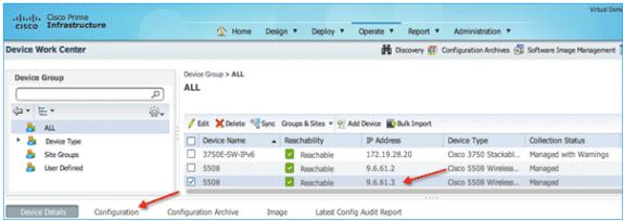
28 Note: Once SSO is enabled, the Standby WLC can be accessed via the console connection, SSH/Telnet on the service port, and SSH on the redundant management interface. WLC 2 on second reboot after downloading XML configuration from Active 8. After SSO is enabled followed by the WLC reboot and XML configuration is synched, WLC 1 will transition its state as Active and WLC 2 will transition its state as STANDBY HOT. From this point onwards, the GUI/Telnet/SSH for WLC 2 on the management interface will not work, as all the configurations and management should be done from the Active WLC. If required, the Standby WLC (WLC 2, in this case) can only be managed via the Console or Service Port. Also, once the Peer WLC transitions to the STANDBY Hot state, the Standby keyword is automatically appended to the Standby WLCs prompt name. 9. Once the HA pairing is formed, NCS removes/deletes the WLC 2 entry from its database as both the WLCs have the same management IP address. For the network, it is the one box which is active in the network.


29 Note: From this image, it is clear that only WLC 1 (with an IP address of and configured as Primary Unit) is active on NCS. WLC 2, which was initially added in NCS with an IP address , is deleted from NCS database after HA pairing is formed. 10. In order to check the redundancy state of the Active WLC from NCS, go to Device Details > Redundancy > Redundancy States. Upgrade the WLC in HA Setup The Standby WLC cannot be upgraded directly from the TFTP/FTP server. After executing all scripts, the Active WLC transfers the image to the Standby WLC. Once the Standby WLC receives the image from the Active WLC, it starts executing upgrade scripts. All the logs for image transfer and script execution on the Standby WLC can be seen on the Active WLC.

30 Upgrade Procedure in HA Setup Complete these steps: 1. After the WLCs are configured in the HA setup, the Standby WLC cannot be upgraded directly from the TFTP/FTP server. 2. Initiate upgrade on the Active WLC in the HA setup via CLI/GUI, and wait for the upgrade to finish. 3. Once the Active WLC executes all the upgrade scripts, it will transfer the entire image to the Standby WLC via the Redundant Port. 4. When the Standby WLC receives the image from the Active WLC, it will start executing the upgrade scripts. The transfer of the image to standby and the execution of the upgrade scripts on the Standby WLC can be seen on the Active WLC Console/Telnet/SSH/Http connection. 5. After a successful message of Standby Upgrade is observed on the Active WLC, it is important to issue the show boot command on the Active WLC in order to make sure the new image is set as the primary image. 6. Once verified, initiate primary image pre download on the Active WLC in order to transfer the new image to all the APs in the network. 7. After pre image is completed on all the APs, issue the show ap image all command in order to verify that the primary image on the WLC is set as the backup image on APs. 8. Initiate swap option to interchange the backup image as primary on the APs. With this implementation, the WLC's and AP's primary image is set to the new image. 9. Issue the schedule reset command as per planned outage with the no swap option in order to reset the APs and WLCs so that they can boot with the new image.
31 10. The Standby WLC will reset just one minute before the scheduled reset time to boot and come up first to take over the network with the new image. 11. All the APs will reboot and join the new Active WLC, and the previous Active WLC will transition to the standby role. 12. Issue the show boot, show sysinfo, show ap image all, and show redundancy summary commands in order to verify that both the WLCs and APs have booted with the new image. Important Guidelines before Initiating a WLC Upgrade in HA Setup Service Upgrade is not supported in this release, so network downtime should be planned before you upgrade the WLCs in the HA setup. The peer should be in the Hot Standby state before you start the upgrade in the HA setup. It is recommended to reboot both the WLCs almost together after upgrade so that there is no software version mismatch. Schedule Reset applies to both the WLCs in the HA setup. The peer WLC reboots one minute before the scheduled timer expiry on the Active WLC. The Standby WLC can be rebooted from the Active WLC using the reset peer system command if a scheduled reset is not planned. Debug transfer can be enabled on the Active WLC as well as the Standby WLC. Download/Upload Facts in HA Setup No direct download and upload configuration is possible from the Standby WLC. All download file types like Image, Configuration, Web Authentication bundle, and Signature Files will be downloaded on the Active WLC first and then pushed automatically to the Standby WLC. Once the configuration file is downloaded on the Active WLC, it is pushed to the Standby WLC. This results in the reset of the Standby WLC first, followed by the reset of the Active WLC. The Peer Service Port and Static route configuration is a part of a different XML file, and will not be applied if downloaded as part of the configuration file. The download of certificates should be done separately on each box and should be done before pairing. Uploading different file types like Configuration, Event Logs, Crash files, and so forth can be done separately from the Standby WLC. However, the CLI to configure different parameters for upload like Server IP, file type, path and name should be done on the Active WLC. Once the upload parameters are configured on the Active WLC, the transfer upload peer start command should be issued on the Active WLC in order to initiate the upload from the Standby WLC. The service port state will be synched from the Active WLC to the Standby WLC. That is, if DHCP is enabled on the Active WLC service port, the Standby WLC will also use DHCP for getting the service port IP address. If the service port of the Active WLC is configured with a Static IP Address, the Standby WLC also needs to be configured with a different Static IP Address. The CLI to configure the IP Address for the Standby WLC service port is configure redundancy interface address peer service port <IP Address >. This command should be executed from the Active WLC. Also, in order to configure the route on the Standby WLC for out of band management on the service port, issue the configure redundancy peer route add <Network IP Address > <IP Mask> <Gateway> command from the Active WLC. Failover Process in the HA Setup In the HA setup, the AP's CAPWAP state in maintained on the Active WLC as well as the Standby WLC (only for APs which are in a Run state). That is, Up Time and Association Up Time is maintained on both the WLC, and when switchover is initiated, the Standby WLC takes over the network. In this example, WLC 1 is in an Active state and serving the network, and WLC 2 is in a Standby state monitoring the Active WLC. Although WLC 2 is in Standby state, it still maintains the CAPWAP state of the AP.
, the direct command is sent from the Active WLC via the Redundant Port as well as from the Redundant Management Interface to the Standby WLC to take over the network.")
32 WLC 1 WLC 2 Failover for WLCs in HA setup can be categorized into two different sections: Box Failover In the case of Box Failover (that is, the Active WLC crashes / system hang / manual reset / force switchover), the direct command is sent from the Active WLC via the Redundant Port as well as from the Redundant Management Interface to the Standby WLC to take over the network. This may take msec depending on the number of APs in the network. In the case of power failure on the Active WLC or some crash where the direct command for switchover cannot be sent, it may take msec depending on the number of APs in network. The time it takes for failover in case of power failure on an Active Box also depends on the keep alive timer configured on the WLC (configured for 100 msec by default). The algorithm it takes to decide the failover is listed here: The Standby WLC sends keep alive to the Active WLC and expects and acknowledgment within 100 msec as per the default timer. This can be configured in range from msec. If there is no acknowledgment of keep alive within 100 msec, the Standby WLC immediately sends an ICMP message to the Active WLC via the redundant management interface in order to check if it is a box failover or some issue with Redundant Port connection. If there is no response to the ICMP message, the Standby WLC gets aggressive and immediately sends another keep alive message to the Standby WLC and expects an acknowledgment in 25% less time (that is, 75 msec or 25% less of 100 msec). If there is no acknowledgment of keep alive within 75 msec, the Standby WLC immediately sends another ICMP message to the Active WLC via the redundant management interface. Again, if there is no response for the second ICMP message, the Standby WLC gets more aggressive and immediately sends another keep alive message to the Standby WLC and expects an acknowledgment in time further 25% of actual timer less from last keep alive timer (that is, 50 msec or last keep alive timer of 75 msec 25% less of 100 msec). If there is no acknowledgment of the third keep alive packet within 50 msec, the Standby WLC immediately sends another ICMP message to the Active WLC via the redundant management interface.
, it may take 3 4 seconds for a complete switchover depending on the number of APs")

33 Finally, if there is no response from the third ICMP packet, the Standby WLC declares the Active WLC is dead and assumes the role of the Active WLC. Network Failover In the case of a Network Failover (that is, the Active WLC cannot reach its gateway for some reason), it may take 3 4 seconds for a complete switchover depending on the number of APs in the network. Steps to Simulate Box Failover Complete these steps: 1. Complete the steps as explained in the configuration section in order to configure HA between two WLCs, and make sure before force switchover is initiated that both the WLCs are paired up as the Active WLC and the Standby WLC. For WLC 1: For WLC 2, go to Console connection: 2. Associate an AP to the WLC and check the status of the AP on both the WLCs. In the HA setup, a mirror copy of the AP database is maintained on both the WLCs. That is, APs CAPWAP state in maintained on Active as well as Standby WLC (only for APs which are in Run state) and when switchover is initiated, the Standby WLC takes over the network. In this example, WLC 1 is an Active WLC, WLC 2 is in a Standby state, and the AP database is maintained on both the WLCs. WLC 1


34 WLC 2 3. Create an open WLAN and associate a client to it. The client database is not synched on the Standby WLC, so the client entry will not be present on the Standby WLC. Once the WLAN is created on the Active WLC, it will also be synched to the Standby WLC via the Redundant Port. WLC 1 WLC 2


35 4. Issue the redundancy force switchover command on the Active WLC. This command will trigger a manual switchover where the Active WLC will reboot and the Standby WLC will take over the network. In this case, the client on the Active WLC will be de authenticated and join back on the new Active WLC. WLC 1 WLC 2 Note: Observe that the prompt in this example changed from 5508 Standby to This is because this WLC is now the Active WLC and the time taken for AP switchover is 1 msec. WLC 2 Note: Observe the AP CAPWAP State on WLC 2, which was the Standby WLC initially and is now the Active WLC after switchover. AP Up Time as well as Association Up Time is maintained, and the AP did not go in to the discovery state. These matrixes provide a clear picture of what condition the WLC Switchover will trigger: Network Issues
36 RP Port Status Up Up Up Up Up Up Up Up Peer Reachable via Redundant Management Gateway Reachable from Active Gateway Reachable from Standby Switchover Results Yes Yes Yes No No Action Standby will reboot and check for gateway Yes Yes No No reachability. Will go in to maintenance mode if still not reachable. Yes No Yes Yes Switchover happens Yes No No No No Action No Yes Yes No No Action Standby will reboot and check for gateway No Yes No No reachability. Will go in to maintenance mode if still not reachable. No No Yes Yes No No No No Switchover happens Standby will reboot and check for gateway reachability. Will go in to maintenance mode if still not reachable. Up Yes Yes Yes No Standby will reboot and check for gateway reachability. Will go in to maintenance
37 Down Down Down Down Down Down Yes Yes No No Yes No Yes No Yes No No No No Yes Yes Yes No Yes No No No No Yes Yes mode if still not reachable. Standby will reboot and check for gateway reachability. Will go in to maintenance mode if still not reachable. Standby will reboot and check for gateway reachability. Will go in to maintenance mode if still not reachable. Standby will reboot and check for gateway reachability. Will go in to maintenance mode if still not reachable. Switchover happens and this may result in Network Conflict Standby will reboot and check for gateway reachability. Will go in to maintenance mode if still not reachable. Switchover happens
38 Down No No No No Standby will reboot and check for gateway reachability. Will go in to maintenance mode if still not reachable. Trigger CP Crash DP Crash System Hang Manual Reset Force Switchover CP Crash DP Crash System Hang Manual Reset Force Switchover CP Crash DP Crash RP Port Status System Issues Peer Reachable via Redundant Management Yes No Yes Yes No Yes Yes No Yes Yes No Yes Yes No Yes No Yes Yes No Yes Yes No Yes Yes No Yes Yes No Yes Yes No No Yes No No Yes Switchover Result Switchover happens Switchover happens Switchover happens Switchover happens Switchover happens Switchover happens Switchover happens Switchover happens Switchover happens Switchover happens As Updated in Network Issue section As Updated in Network Issue section System No No Yes As Updated
39 Hang Manual Reset Force Switchover No No Yes No No Yes in Network Issue section As Updated in Network Issue section As Updated in Network Issue section HA Facts HA Pairing is possible only between the same type of hardware and software versions. Mismatch may result in Maintenance Mode. The Virtual IP Address should be the same on both the WLCs before configuring AP SSO. Direct connectivity is recommended between the Active and Standby Redundant Port for 5500/7500/8500 Series of WLCs. WiSM 2 WLCs should be in same 6500 chassis or can be installed in VSS setup for reliable performance. A physical connection between Redundant Port and Infrastructure Network should be done prior to HA configuration. The Primary units MAC should be used as Mobility MAC in the HA setup in order to form a mobility peer with another HA setup or independent controller. You also have the flexibility to configure a custom MAC address, which can be used as a Mobility MAC address using the configure redundancy mobilitymac <custom mac address> command. Once configured, you should use this MAC address to form a mobility peer instead of using the system MAC address. Once HA is configured, this MAC cannot be changed. It is recommended that you use DHCP address assignment for the service port in the HA setup. After HA is enabled, if the static IP is configured for service port, WLC loses the service port IP and it has to be configured again. When AP SSO is enabled, there is no SNMP/GUI access on the service port for both the WLCs in the HA setup. Configurations like changing virtual IP address, enabling secureweb mode, configuring web auth proxy, and so forth need a WLC reboot in order to get implemented. In this case, a reboot of the Active WLC will also trigger a simultaneous reboot of the Standby WLC. When AP SSO is disabled on the Active WLC, it will be pushed to the Standby WLC. After reboot, all the ports will come up on the Active WLC and will be disabled on the Standby WLC. Keep alive and Peer Discovery timers should be left with default timer values for better performance. Clear configuration on the Active WLC will also initiate clear configuration on the Standby WLC. Internal DHCP is not supported when AP SSO is enabled. SSO for LSC AP is not supported. L2 MGID is synched, but the L3 MGID database is cleared with SSO. Maintenance Mode There are few scenarios where the Standby WLC may go into Maintenance Mode and not be able to communicate with the network and peer: Non reachability to Gateway via Redundant Management Interface WLC with HA SKU which had never discovered peer


40 Redundant Port is down Software version mismatch (WLC which boots up first goes into active mode and the other WLC in Maintenance Mode) Note: The WLC should be rebooted in order to bring it out of Maintenance Mode. Only the Console and Service Port is active in Maintenance Mode. AP SSO Deployment with Legacy Primary/Secondary/Tertiary HA HA (that is, AP SSO) can be deployed with Secondary and Tertiary Controllers just like today. Both Active and Standby WLCs combined in the HA setup should be configured as primary WLC. Only on failure of both Active and Standby WLCs in the HA setup will the APs fall back to Secondary and further to Tertiary WLCs. AP SSO Deployment in Mobility Setup Each WLC has its own unique MAC address, which is used in mobility configuration with an individual controller management IP address. In HA (that is, AP SSO) setup, both the WLCs (Primary and Standby) have their own unique MAC address. In the event of failure of the Primary box and Standby takes over the network if the MAC address of the Primary box is used on another controllers in mobility setup, control path

41 and data path will be down and user has to manually change the MAC to standby MAC address on all the controllers in mobility setup. This is a really cumbersome process as a lot of manual intervention is required. In order to keep the mobility network stable without any manual intervention and in the event of failure or switchover, the back and forth concept of Mobility MAC has been introduced. When the HA pair is set up, by default, the Primary WLC's MAC address is synched as the Mobility MAC address on the Standby WLC which can be seen via the show redundancy summary command on both the controllers. In this output, captured from a Standby controller, the Mobility MAC address can be observed, which is different from the Standbys own MAC address seen as Unit ID. This MAC address is synched from the Active WLC and should be used in mobility configuration. With this implementation, if the Active WLC goes down or even if it is replaced, the Mobility MAC address is still available and active on the Standby WLC and the mobility tunnels will always stay up. In case the new controller is introduced in the network because of the replacement of the previous Active WLC, it will transition its state as Standby and the same Mobility MAC address is synched again to the new Standby WLC. You have the flexibility to configure a custom MAC address as Mobility MAC instead of using the default behavior of using the Active WLC MAC address as Mobility MAC. This can be done using the configure redundancy mobilitymac <custom mac address> command on the Active WLC. Once configured, you should use this MAC address on other controllers in order to form a mobility peer instead of using the Active WLC MAC address. This MAC address should be configured before forming the HA pair. Once the HA pair is formed, the Mobility MAC cannot be changed or edited.

42 In this topology, the Primary and Standby have their own MAC address. With HA pairing, the Active WLC MAC address is synched as a Mobility MAC address, which is the default behavior if a custom MAC is not configured before HA pairing. Once the Active WLC MAC address is synched as the Mobility MAC address, the same MAC is used in mobility configuration on all the controllers in the mobility setup. Licensing for HA Pair A HA Pair can be established between two WLCs running in these combinations: One WLC has a valid AP Count license and the other WLC has a HA SKU UDI Both the WLCs have a valid AP Count license One WLC has an Evaluation license and the other WLC has a HA SKU UDI or Permanent license One WLC has a valid AP Count license and the other WLC has a HA SKU UDI HA SKU is a new SKU with a Zero AP Count License. The device with HA SKU becomes Standby the first time it pairs up. AP count license info will be pushed from Active to Standby. On event of Active failure, HA SKU will let APs join with AP count obtained and will start 90 day countdown. The granularity of this is in days. After 90 days, it starts nagging messages. It will not disconnect connected APs. With new WLC coming up, HA SKU at the time of paring will get the AP Count: If the new WLC has a higher AP count than the previous, the 90 day counter is reset. If the new WLC has a lower AP count than the previous, the 90 day counter is not reset. In order to lower AP count after switchover, the WLC offset timer will continue and nagging messages will be displayed after time expiry. Elapsed time and AP count will be remembered on reboot.
43 The factory default HA SKU controller should not allow any APs to join. Both the WLCs have a valid AP Count license The CLI should be used to configure one WLC as the Standby WLC (as mentioned in the configuration section) provided it satisfies the requirement of minimum permanent license count (50 on the 5500, 100 on WiSM 2, and 300 on the 7500/8500). AP count license information will be pushed from Active to Standby. In the event of a switchover, the new Active WLC will operate with the license count of the previous Active WLC and will start the 90 day countdown. The WLC configured as Secondary will not use its own installed license, and only the inherited license from the active will be utilized. After 90 days, it starts nagging messages. It will not disconnect connected APs. With the new WLC coming up, HA SKU at the time of paring will get the AP Count: If the new WLC has a higher AP count than the previous, the 90 day counter is reset. If the new WLC has a lower AP count than the previous, the 90 day counter is not reset. After switchover to a lower AP count, the WLC offset timer will continue and nagging messages will be displayed after time expiry. One WLC has an Evaluation license and the other WLC has a HA SKU UDI or Permanent license The device with HA SKU becomes the Standby WLC the first time it pairs up with an existing Active WLC running Evaluation License. Or, any WLC running a permanent license count can be configured as the Secondary unit using the CLI configuration provided if it satisfies the requirement of minimum permanent license count (50 on the 5500, 100 on WiSM 2, and 300 on the 7500/8500). AP count license information will be pushed from Active to Standby. In the event of a switchover, the new Active WLC will operate with the license count of the previous Active WLC and start the 90 day countdown. After 90 days, it starts nagging messages. It will not disconnect connected APs. With new the WLC coming up, HA SKU at the time of paring will get the AP Count: Glossary If the new WLC has a higher AP count than the previous, the 90 day counter is reset. If the new WLC has a lower AP count than the previous, the 90 day counter is not reset. After switchover to a lower AP count, the WLC offset timer will continue and nagging messages will be displayed after time expiry. AP SSO Access Point Stateful Switchover where the CAPWAP state for each AP is maintained on the Active and Standby WLCs, and the CAPWAP state is retained after switchover to the Standby WLC. An AP need not go through CAPWAP discovery and join the process after failover. Client SSO Wireless Client Stateful Switchover where the client state is also maintained on the Active and Standby WLCs, and the wireless clients are not de authenticated after switchover. This will be supported in a future release. Redundancy Port Physical Port on the 5500/7500/8500 WLC for HA role negotiation, configuration sync, and redundancy messages between the Active and Standby WLCs. Redundancy VLAN VLAN created on the Catalyst 6500 Sup for WiSM 2 Redundancy Port that is connected to the Catalyst 6k backplane in order to exchange configuration and redundancy messages
44 including HA role negotiation between the Active and Standby WLCs. Redundancy Management Interface A parallel interface to the management interface on both the WLCs in the HA setup. Should be in the same subnet as the management interface. This interface lets the Standby WLC interact with infra network and also exchange some redundancy messages over infra network between the Active and Standby WLCs. Active WLC This is the WLC which is currently active in the HA pair and is taking care of the wireless network. APs establish a single CAPWAP tunnel with the Active WLC. Standby WLC This is the WLC that is monitoring the active controller in the HA pair, and is ready to take over the wireless network in the event of Active WLC failure. Peer AP SSO is a box to box redundancy (that is, 1:1) so both the WLCs (Active and Standby) in the HA setup are peers to each other. Primary Unit In AP SSO deployment, the controller running the higher permanent count licenses should be configured as the Primary unit. The Primary Unit is the WLC, which will take the role of the Active WLC the first time it forms a HA pair. The Primary Unit sends the license count information to its peer via the Redundant Port. Secondary Unit In AP SSO deployment, the controller running lower or equal permanent count licenses should be configured as the Secondary Unit or the controller with HA SKU UDI (zero ap count license) is shipped default as Secondary Unit. The Secondary Unit is the WLC, which will take the role of the Standby WLC the first time it forms a HA pair. The Secondary Unit inherits the license count information from its peer(that is, the Active WLC) via the Redundant Port. Maintenance Mode When the Standby WLC cannot communicate to the gateway or cannot discover the peer WLC (that is, the Active WLC) via the Redundant Port, it goes in to Maintenance Mode. In this mode, the WLC cannot communicate to the infra network and will not participate in the HA process. Since the WLC in Maintenance Mode does not participate in the HA process, it needs to be manually rebooted in order to bring it out of Maintenance Mode and participate in the HA process again. Mobility MAC A unique MAC address shared between peers in the HA setup. This MAC address should be used to form a mobility pair between the HA setup and another WLC in the HA setup or with independent controllers. By default, the Active WLC MAC address is shared as the Mobility MAC address, but Mobility MAC can also be manually configured on the Active WLC using a CLI, which will be shared between peers in the HA setup. Keep Alive Timer In the HA setup, the Standby WLC sends keep alive packets on the Redundancy Port in order to check the health of the Active WLC. With no acknowledgment of three keep alive packets from the Active WLC, the Standby WLC declares the Active WLC as dead and takes over the network. Peer Search Timer While booting, the Standby WLC waits for the peer search timer (default of 2 minutes) in order to discover the peer. If the WLC cannot discover its peer within this time, it will transition its state to Maintenance Mode. Related Information Technical Support & Documentation Cisco Systems Contacts & Feedback Help Site Map
Best practices to deploy high-availability in Wireless LAN Architectures
 Best practices to deploy high-availability in Wireless LAN Architectures Simone Arena Wireless Networking Group, TME Abstract The proliferation of Wi-Fi enabled devices creates a significant challenge
Best Practices to Deploy High-Availability in Wireless LAN Architectures
 Best Practices to Deploy High-Availability in Wireless LAN Architectures Brian Levin ENG, Technical Marketing Engineer The New Normal High Density How many devices have you got today? High Quality No coverage
Configuring High Availability (HA)
") 4 CHAPTER This chapter covers the following topics: Adding High Availability Cisco NAC Appliance To Your Network, page 4-1 Installing a Clean Access Manager High Availability Pair, page 4-3 Installing
4 CHAPTER This chapter covers the following topics: Adding High Availability Cisco NAC Appliance To Your Network, page 4-1 Installing a Clean Access Manager High Availability Pair, page 4-3 Installing
Managing Software. Upgrading the Controller Software. Considerations for Upgrading Controller Software
 Upgrading the Controller Software, on page 1 Considerations for Upgrading Controller Software, on page 1 Upgrading Controller Software (GUI), on page 2 Upgrading Controller Software (CLI), on page 5 Predownloading
Cisco 8500 Series Wireless Controller Deployment Guide
 Cisco 8500 Series Wireless Controller Deployment Guide Document ID: 113695 Contents Introduction Prerequisites Requirements Components Used Conventions Product Overview Product Specifications Features
Using Access Point Communication Protocols
 Information About Access Point Communication Protocols, page 1 Restrictions for Access Point Communication Protocols, page 2 Configuring Data Encryption, page 2 Viewing CAPWAP Maximum Transmission Unit
Configuring Auto-Anchor Mobility
 Information About Auto-Anchor Mobility, page 1 Guest Anchor Priority, page 5 Information About Auto-Anchor Mobility You can use auto-anchor mobility (also called guest tunneling) to improve load balancing
Lightweight AP (LAP) Registration to a Wireless LAN Controller (WLC)
 Registration to a Wireless LAN Controller (WLC)") Lightweight AP (LAP) Registration to a Wireless LAN Controller (WLC) Document ID: 70333 Introduction Prerequisites Requirements Components Used Conventions Background Information Register the LAP with
Lightweight AP (LAP) Registration to a Wireless LAN Controller (WLC) Document ID: 70333 Introduction Prerequisites Requirements Components Used Conventions Background Information Register the LAP with
Overview of Ports and Interfaces
 Three concepts are key to understanding how controllers connect to a wireless network: ports, interfaces, and WLANs. Information About Ports, page 1 Information About Distribution System Ports, page 2
Ports and Interfaces. Ports. Information About Ports. Ports, page 1 Link Aggregation, page 5 Interfaces, page 10
 Ports, page 1 Link Aggregation, page 5 Interfaces, page 10 Ports Information About Ports A port is a physical entity that is used for connections on the Cisco WLC platform. Cisco WLCs have two types of
Best Practices to Deploy High-Availability in Wireless LAN Architectures
 Best Practices to Deploy High-Availability in Wireless LAN Architectures Kara Muessig Technical Solutions Architect CCIE (Wireless) #29572 Planned downtime Failover Redundancy Survivability Clustering/Pooling
Configuring VRRP. Finding Feature Information. The Virtual Router Redundancy Protocol (VRRP) is an election protocol that dynamically assigns
 is an election protocol that dynamically assigns") The Virtual Router Redundancy Protocol (VRRP) is an election protocol that dynamically assigns responsibility for one or more virtual routers to the VRRP routers on a LAN, allowing several routers on a
The Virtual Router Redundancy Protocol (VRRP) is an election protocol that dynamically assigns responsibility for one or more virtual routers to the VRRP routers on a LAN, allowing several routers on a
Setting Up Hardware Failover
 C HAPTER 51 Setting Up Hardware Failover Chapter 51: Hardware Failover > Settings Hardware Failover allows two identical SonicWALL PRO Series security appliances running SonicOS Enhanced to be configured
Configuring Backup Controllers
 Information About, page 1 Restrictions for, page 2 (GUI), page 2 (CLI), page 3 Information About A single controller at a centralized location can act as a backup for access points when they lose connectivity
Cisco Exam Troubleshooting Cisco Wireless Enterprise Networks Version: 7.0 [ Total Questions: 60 ]
![Cisco Exam Troubleshooting Cisco Wireless Enterprise Networks Version: 7.0 [ Total Questions: 60 ]](/thumbs/85/92129635.jpg "Cisco Exam Troubleshooting Cisco Wireless Enterprise Networks Version: 7.0 [ Total Questions: 60 ]") s@lm@n Cisco Exam 300-370 Troubleshooting Cisco Wireless Enterprise Networks Version: 7.0 [ Total Questions: 60 ] Cisco 300-370 : Practice Test Question No : 1 An engineer must open a support case with
s@lm@n Cisco Exam 300-370 Troubleshooting Cisco Wireless Enterprise Networks Version: 7.0 [ Total Questions: 60 ] Cisco 300-370 : Practice Test Question No : 1 An engineer must open a support case with
Troubleshooting Web Authentication on a Wireless LAN Controller (WLC)
") Troubleshooting Web Authentication on a Wireless LAN Controller (WLC) Document ID: 108501 Contents Introduction Prerequisites Requirements Components Used Related Products Conventions Web Authentication
Troubleshooting Web Authentication on a Wireless LAN Controller (WLC) Document ID: 108501 Contents Introduction Prerequisites Requirements Components Used Related Products Conventions Web Authentication
Configuring Link Aggregation
 Information About Link Aggregation, page 1 Restrictions for Link Aggregation, page 2 (GUI), page 4 (CLI), page 4 Verifying Link Aggregation Settings (CLI), page 5 Configuring Neighbor Devices to Support
Politecnico di Torino Network architecture and management. Outline 11/01/2016. Marcello Maggiora, Antonio Lantieri, Marco Ricca
 Politecnico di Torino Network architecture and management Marcello Maggiora, Antonio Lantieri, Marco Ricca Outline Politecnico di Torino network: Overview Building blocks: Edge, Core, Distribution, Access
Ensure that you meet these requirements before you attempt this configuration:
 Contents Introduction Prerequisites Requirements Components Used Conventions Network Diagram Configure Configure Mobility Groups for the WLCs Assign Primary, Secondary, and Tertiary Controllers for the
Configuring OfficeExtend Access Points
 Information About OfficeExtend Access Points, page 1 OEAP 600 Series Access Points, page 2 OEAP in Local Mode, page 3 Supported WLAN Settings for 600 Series OfficeExtend Access Point, page 3 WLAN Security
Managing Switch Stacks
 Finding Feature Information, page 1 Prerequisites for Switch Stacks, page 1 Restrictions for Switch Stacks, page 2 Information About Switch Stacks, page 2 How to Configure a Switch Stack, page 14 Troubleshooting
Configuring Link Aggregation
 Information About Link Aggregation, page 1 Restrictions for Link Aggregation, page 1 (GUI), page 3 (CLI), page 4 Verifying Link Aggregation Settings (CLI), page 4 Configuring Neighbor Devices to Support
Configuring the Switch for Access Point Discovery
 Configuring the Switch for Access Point Discovery Finding Feature Information, on page 1 Prerequisites for, on page 1 Restrictions for, on page 2 Information About, on page 2 How to Configure Access Point
Deployment Guide for Cisco Guest Access Using the Cisco Wireless LAN Controller, Release 4.1
 Deployment Guide for Cisco Guest Access Using the Cisco Wireless LAN Controller, Release 4.1 Last revised: February 1, 2008 Contents Overview section on page 1 Configuring Guest Access on the Cisco Wireless
Securing Wireless LAN Controllers (WLCs)
") Securing Wireless LAN Controllers (WLCs) Document ID: 109669 Contents Introduction Prerequisites Requirements Components Used Conventions Traffic Handling in WLCs Controlling Traffic Controlling Management
Securing Wireless LAN Controllers (WLCs) Document ID: 109669 Contents Introduction Prerequisites Requirements Components Used Conventions Traffic Handling in WLCs Controlling Traffic Controlling Management
Configuring Failover. Understanding Failover CHAPTER
 CHAPTER 14 This chapter describes the security appliance failover feature, which lets you configure two security appliances so that one takes over operation if the other one fails. The ASA 5505 series
WLC 7.0 and Later: VLAN Select and Multicast Optimization Features Deployment Guide
 WLC 7.0 and Later: VLAN Select and Multicast Optimization Features Deployment Guide Document ID: 112932 Contents Introduction Prerequisites Requirements Platforms Supported Conventions VLAN Select Feature
Using the Web Graphical User Interface
 Prerequisites for Using the Web GUI, page 1 Information About Using The Web GUI, page 1 Connecting the Console Port of the Device, page 3 Logging On to the Web GUI, page 3 Enabling Web and Secure Web Modes,
Lesson Overview & Objectives
 Cisco Unified Wireless Network Administration: AP Association Finding a Controller Cisco Unified Wireless Network Administration: AP Association - Finding a Controller 2010 Cisco Systems, Inc. All rights
Multicast VLAN, page 1 Passive Clients, page 2 Dynamic Anchoring for Clients with Static IP Addresses, page 5
 Multicast VLAN, page 1 Passive Clients, page 2 Dynamic Anchoring for Clients with Static IP Addresses, page 5 Multicast VLAN Information About Multicast Optimization Prior to the 7.0.116.0 release, multicast
DHCP. DHCP Proxy. Information About Configuring DHCP Proxy. Restrictions on Using DHCP Proxy
 Proxy, page 1 Link Select and VPN Select, page 4 Option 82, page 7 Internal Server, page 10 for WLANs, page 13 Proxy Information About Configuring Proxy When proxy is enabled on the controller, the controller
Firepower Threat Defense Cluster for the Firepower 4100/9300
 Firepower Threat Defense Cluster for the Firepower 4100/9300 Clustering lets you group multiple Firepower Threat Defense units together as a single logical device. Clustering is only supported for the
Smart Install Concepts
 CHAPTER 1 Smart Install is a plug-and-play configuration and image-management feature that provides zero-touch deployment for new switches. This means that a customer can ship a switch to a location, place
Configuring VRRP. Finding Feature Information. Contents
 Configuring VRRP First Published: May 2, 2005 Last Updated: July 30, 2010 The Virtual Router Redundancy Protocol (VRRP) is an election protocol that dynamically assigns responsibility for one or more virtual
Use Plug and Play to Deploy New Devices
 About Plug and Play, page 1 Prerequisites for Using Plug and Play, page 2 Plug and Play Workflow, page 2 Use the Plug and Play Dashboard to Monitor New Device Deployments, page 4 Create Plug and Play Profiles
Mobility Groups. Information About Mobility
 Information About Mobility, page 1 Information About, page 5 Prerequisites for Configuring, page 10 Configuring (GUI), page 12 Configuring (CLI), page 13 Information About Mobility Mobility, or roaming,
Web Authentication Proxy on a Wireless LAN Controller Configuration Example
 Web Authentication Proxy on a Wireless LAN Controller Configuration Example Document ID: 113151 Contents Introduction Prerequisites Requirements Components Used Conventions Web Authentication Proxy on
Configure Site Network Settings
 About Global Network Settings, page 1 About Device Credentials, page 2 Configure Global Device Credentials, page 4 Configure IP Address Pools, page 9 Configure Global Network Servers, page 9 Configure
Wireless LAN Controller Module Configuration Examples
 Wireless LAN Controller Module Configuration Examples Document ID: 70530 Contents Introduction Prerequisites Requirements Components Used Conventions Basic Configuration Example 1 Basic Configuration with
Wireless LAN Controller (WLC) Mobility Groups FAQ
 Mobility Groups FAQ") Wireless LAN Controller (WLC) Mobility Groups FAQ Document ID: 107188 Contents Introduction What is a Mobility Group? What are the prerequisites for a Mobility Group? How do I configure a Mobility Group
Wireless LAN Controller (WLC) Mobility Groups FAQ Document ID: 107188 Contents Introduction What is a Mobility Group? What are the prerequisites for a Mobility Group? How do I configure a Mobility Group
Configuring EtherChannels and Layer 2 Trunk Failover
 35 CHAPTER Configuring EtherChannels and Layer 2 Trunk Failover This chapter describes how to configure EtherChannels on Layer 2 and Layer 3 ports on the switch. EtherChannel provides fault-tolerant high-speed
Cisco 440X Series Wireless LAN Controllers Deployment Guide
 Cisco 440X Series Wireless LAN Controllers Deployment Guide Cisco customers are rapidly adopting the Cisco Unified Wireless Network architecture for next generation wireless LAN performance and advanced
Configuring FlexConnect Groups
 Information About FlexConnect Groups, page 1, page 5 Configuring VLAN-ACL Mapping on FlexConnect Groups, page 10 Configuring WLAN-VLAN Mappings on FlexConnect Groups, page 11 Information About FlexConnect
Configuring VIP and Virtual Interface Redundancy
 CHAPTER 6 Configuring VIP and Virtual Interface Redundancy This chapter describes how to plan for and configure virtual IP (VIP) redundancy and virtual interface redundancy on the CSS. Information in this
Configuring Auto-Anchor Mobility
 Information About Auto-Anchor Mobility, page 1 Information About Auto-Anchor Mobility You can use auto-anchor mobility (also called guest tunneling) to improve load balancing and security for roaming clients
Using the Web Graphical User Interface
 Prerequisites for Using the Web GUI, page 1 Information About Using The Web GUI, page 2 Connecting the Console Port of the Switch, page 3 Logging On to the GUI, page 4 Enabling Web and Secure Web Modes,
AP Connectivity to Cisco WLC
 CAPWAP, page 1 Discovering and Joining Cisco WLC, page 12 Authorizing Access Points, page 23 AP 802.1X Supplicant, page 29 Infrastructure MFP, page 34 Troubleshooting the Access Point Join Process, page
Linksys Stackable Switches
 TECHNICAL BULLETIN Linksys Stackable Switches How to Build Stacks and Understand Their Operation This document describes how to stack Linksys switches and covers advanced stacking information, as well
Troubleshooting CHAPTER
 CHAPTER 3 This chapter provides troubleshooting procedures for basic problems with the access point. For the most up-to-date, detailed troubleshooting information, refer to the Cisco Technical Support
FlexConnect. Information About FlexConnect
 Information About, on page 1 Restrictions on, on page 6 Configuring, on page 8 Information About (previously known as Hybrid Remote Edge Access Point or H-REAP) is a wireless solution for branch office
Configuring Virtual Port Channels
 This chapter contains the following sections: Information About vpcs, page 1 Guidelines and Limitations for vpcs, page 10 Configuring vpcs, page 11 Verifying the vpc Configuration, page 25 vpc Default
Zone-Based Policy Firewall High Availability
 The feature enables you to configure pairs of devices to act as backup for each other. High availability can be configured to determine the active device based on a number of failover conditions. When
Configuring FlexConnect Groups
 Information About FlexConnect Groups, page 1, page 3 Configuring VLAN-ACL Mapping on FlexConnect Groups, page 8 Information About FlexConnect Groups To organize and manage your FlexConnect access points,
Cisco Deploying Basic Wireless LANs
 Cisco Deploying Basic Wireless LANs WDBWL v1.2; 3 days, Instructor-led Course Description This 3-day instructor-led, hands-on course is designed to give you a firm understanding of the Cisco Unified Wireless
DEPLOYING BASIC CISCO WIRELESS LANS (WDBWL)
") [Type a quote from the document or the summary of an interesting point. You can position the text box anywhere in the document. Use the Drawing Tools tab to change the formatting of the pull quote text
[Type a quote from the document or the summary of an interesting point. You can position the text box anywhere in the document. Use the Drawing Tools tab to change the formatting of the pull quote text
Configuring EtherChannels and Link-State Tracking
 CHAPTER 37 Configuring EtherChannels and Link-State Tracking This chapter describes how to configure EtherChannels on Layer 2 and Layer 3 ports on the switch. EtherChannel provides fault-tolerant high-speed
Chapter 3 Managing System Settings
 Chapter 3 Managing System Settings Using the System Settings Utility The navigation pane at the top of the web browser interface contains a System tab that enables you to manage your FS700TSSmart Switch
Laboration 2 Troubleshooting Switching and First-Hop Redundancy
 Laboration 2 Troubleshooting Switching and First-Hop Redundancy Topology All contents are Copyright 1992 2011 Cisco Systems, Inc. All rights reserved. This document is Cisco Public Information. Page 1
Configuring Virtual Port Channels
 Configuring Virtual Port Channels This chapter describes how to configure virtual port channels (vpcs) on Cisco Nexus 5000 Series switches. It contains the following sections: Information About vpcs, page
First Hop Redundancy Protocols Configuration Guide, Cisco IOS XE Release 3SE (Catalyst 3850 Switches)
") First Hop Redundancy Protocols Configuration Guide, Cisco IOS XE Release 3SE (Catalyst 3850 Switches) Americas Headquarters Cisco Systems, Inc. 170 West Tasman Drive San Jose, CA 95134-1706 USA http://www.cisco.com
First Hop Redundancy Protocols Configuration Guide, Cisco IOS XE Release 3SE (Catalyst 3850 Switches) Americas Headquarters Cisco Systems, Inc. 170 West Tasman Drive San Jose, CA 95134-1706 USA http://www.cisco.com
Cisco Network Plug and Play Agent Configuration Guide, Cisco IOS XE Everest b
 Cisco Network Plug and Play Agent Configuration Guide, Cisco IOS XE Everest 16.5.1b Feature Information for Cisco Network Plug and Play Agent 2 Finding Feature Information 3 Prerequisites for Cisco Network
FortiNAC. Cisco Airespace Wireless Controller Integration. Version: 8.x. Date: 8/28/2018. Rev: B
 FortiNAC Cisco Airespace Wireless Controller Integration Version: 8.x Date: 8/28/2018 Rev: B FORTINET DOCUMENT LIBRARY http://docs.fortinet.com FORTINET VIDEO GUIDE http://video.fortinet.com FORTINET KNOWLEDGE
Campus network: Looking at the big picture
 Outline Politecnico di Torino architecture and management Marcello Maggiora, Antonio Lantieri, Marco Ricca Building blocks Core, Distribution, Access, Edge network architecture Core network Distribution
Software-Defined Access Wireless
 Introduction to, page 1 Configuring SD-Access Wireless (CLI), page 7 Enabling SD-Access Wireless (GUI), page 8 Configuring SD-Access Wireless VNID (GUI), page 9 Configuring SD-Access Wireless WLAN (GUI),
High Availability Synchronization PAN-OS 5.0.3
 High Availability Synchronization PAN-OS 5.0.3 Revision B 2013, Palo Alto Networks, Inc. www.paloaltonetworks.com Contents Overview... 3 Device Configuration... 4 Network Configuration... 9 Objects Configuration...
Cisco Branch Routers Series Network Analysis Module (NME-NAM-120S) Installation and Configuration Note, 4.2
 Installation and Configuration Note, 4.2") Cisco Branch Routers Series Network Analysis Module (NME-NAM-120S) Installation and Configuration Note, 4.2 The Cisco Network Analysis Module (NAM) is an integrated module that enables network managers
Cisco Branch Routers Series Network Analysis Module (NME-NAM-120S) Installation and Configuration Note, 4.2 The Cisco Network Analysis Module (NAM) is an integrated module that enables network managers
Converting Autonomous Access Points to Lightweight Mode
 Converting Autonomous Access Points to Lightweight Mode Finding Feature Information, page 1 Prerequisites for Converting Autonomous Access Points to Lightweight Mode, page 1 Information About Autonomous
Client Data Tunneling
 Ethernet over GRE Tunnels, on page 1 Proxy Mobile IPv6, on page 9 Ethernet over GRE Tunnels Ethernet over GRE (EoGRE) is a new aggregation solution for aggregating Wi-Fi traffic from hotspots. This solution
Converting Autonomous Access Points to Lightweight Mode
 Converting Autonomous Access Points to Lightweight Mode Finding Feature Information, on page 1 Prerequisites for, on page 1 Information About Autonomous Access Points Converted to Lightweight Mode, on
Finding Support Information for Platforms and Cisco IOS Software Images
 First Published: June 19, 2006 Last Updated: June 19, 2006 The Cisco Networking Services () feature is a collection of services that can provide remote event-driven configuring of Cisco IOS networking
Upgrading from TrafficShield 3.2.X to Application Security Module 9.2.3
 Upgrading from TrafficShield 3.2.X to Application Security Module 9.2.3 Introduction Preparing the 3.2.X system for the upgrade Installing the BIG-IP version 9.2.3 software Licensing the software using
Deploying Cisco Wireless Enterprise Networks
 300-365 Deploying Cisco Wireless Enterprise Networks NWExam.com SUCCESS GUIDE TO CISCO CERTIFICATION Exam Summary Syllabus Questions Table of Contents Introduction to 300-365 Exam on Deploying Cisco Wireless
Software-Defined Access Wireless
 Introduction to, page 1 Configuring SD-Access Wireless (CLI), page 7 Enabling SD-Access Wireless (GUI), page 8 Configuring SD-Access Wireless VNID (GUI), page 9 Configuring SD-Access Wireless WLAN (GUI),
The information in this document is based on the Cisco VPN 3000 Series Concentrator.
 What Is VRRP? Document ID: 7210 Contents Introduction Prerequisites Requirements Components Used Conventions How Does the VPN 3000 Concentrator Implement VRRP? Configure VRRP Synchronize the Configurations
Configuring Box-to-Box Redundancy
 CHAPTER 3 This chapter describes how to configure redundancy between two identically configured Cisco Content Services Switches (CSSs). Information in this chapter applies to all CSS models, except where
Configuring RPR and RPR+ Supervisor Engine Redundancy
 CHAPTER 8 Configuring RPR and RPR+ Supervisor Engine Redundancy This chapter describes how to configure supervisor engine redundancy using route processor redundancy (RPR) and RPR+. For complete syntax
Cisco Wireless Devices Association Matrix
 Cisco Wireless Devices Association Matrix Document ID: 19242 In order to get Cisco Aironet drivers, firmware and utility software, refer to Cisco Wireless Downloads. Contents Introduction Prerequisites
Symbols. Numerics I N D E X
 I N D E X Symbols /var/log/ha-debug log, 517 /var/log/ha-log log, 517 Numerics A 3500XL Edge Layer 2 switch, configuring AD SSO, 354 355 access to resources, troubleshooting issues, 520 access VLANs, 54
Configuring Hybrid REAP
 13 CHAPTER This chapter describes hybrid REAP and explains how to configure this feature on controllers and access points. It contains the following sections: Information About Hybrid REAP, page 13-1,
Configuring Stateful Interchassis Redundancy
 The Stateful Interchassis Redundancy feature enables you to configure pairs of devices to act as backups for each other. This module describes conceptual information about and tasks for configuring stateful
Using the CLI to Configure the Syslog Server for Access Points
 Chapter 8 Autonomous Access Points Converted to Lightweight Mode Using the CLI to Configure the Syslog Server for Access Points To configure the syslog server for access points using the controller CLI,
Interfaces for Firepower Threat Defense
 This chapter includes Firepower Threat Defense interface configuration including Ethernet settings, EtherChannels, VLAN subinterfaces, IP addressing, and more. About Firepower Threat Defense Interfaces,
The information in this document is based on these software and hardware versions:
 Introduction This document describes how to configure a Lightweight Access Point as a 802.1x supplicant to authenticate against a RADIUS Server such as ACS 5.2. Prerequisites Requirements Ensure that you
DWS-4000 Series DWL-3600AP DWL-6600AP
 Unified Wired & Wireless Access System Configuration Guide Product Model: Release 1.0 DWS-4000 Series DWL-8600AP DWL-6600AP DWL-3600AP Page 1 Table of Contents 1. Scenario 1 - Basic L2 Edge Setup: 1 Unified
Cisco IOS Commands. abort CHAPTER
 CHAPTER 2 abort Use the abort VLAN database command to abandon the proposed new VLAN database, exit VLAN database mode, and return to privileged EXEC mode. abort This command has no arguments or keywords.
Deployment Guide for SRX Series Services Gateways in Chassis Cluster Configuration
 Deployment Guide for SRX Series Services Gateways in Chassis Cluster Configuration Version 1.2 June 2013 Juniper Networks, 2013 Contents Introduction... 3 Chassis Cluster Concepts... 4 Scenarios for Chassis
Release Notes. Release Purpose... 1 Platform Compatibility... 1 Upgrading Information... 1 Browser Support... 1 Known Issues... 2 Resolved Issues...
 SonicOS SonicOS Contents Release Purpose... 1 Platform Compatibility... 1 Upgrading Information... 1 Browser Support... 1 Known Issues... 2 Resolved Issues... 6 Release Purpose SonicOS 6.1.1.4 is a maintenance
Configure 802.1x Authentication with PEAP, ISE 2.1 and WLC 8.3
 Configure 802.1x Authentication with PEAP, ISE 2.1 and WLC 8.3 Contents Introduction Prerequisites Requirements Components Used Configure Network Diagram Configuration Declare RADIUS Server on WLC Create
Configuring the AP-Manager Interface
 Information About AP-Manager Interface, page 1 Restrictions for Configuring AP Manager Interface, page 2 (GUI), page 2 Configuring the AP Manager Interface (CLI), page 3 Configuration Example: Configuring
Grandstream Networks, Inc. GWN76xx Wi-Fi Access Points Master/Slave Architecture Guide
 Grandstream Networks, Inc. GWN76xx Wi-Fi Access Points Master/Slave Architecture Guide Table of Contents INTRODUCTION... 4 DISCOVER AND PAIR GWN76XX ACCESS POINTS... 5 Discover GWN76xx... 5 Method 1: Discover
Configuring Controller Settings
 CHAPTER 4 This chapter describes how to configure settings on the controller. It contains these sections: Installing and Configuring Licenses, page 4-2 Configuring 802.11 Bands, page 4-26 Configuring 802.11n
Stack Manager and High Availability
 debug platform stack-manager, on page 2 mode sso, on page 3 main-cpu, on page 4 policy config-sync prc reload, on page 5 mode sso, on page 6 policy config-sync prc reload, on page 7 redundancy config-sync
CCIE Wireless v3 Lab Video Series 1 Table of Contents
 CCIE Wireless v3 Lab Video Series 1 Table of Contents Section 1: Network Infrastructure Layer 2 Technologies VLANs VTP Layer 2 Interfaces DTP Spanning Tree- Root Election Spanning Tree- Path Control Spanning
Wireless LAN Controller Web Authentication Configuration Example
 Wireless LAN Controller Web Authentication Configuration Example Document ID: 69340 Contents Introduction Prerequisites Requirements Components Used Conventions Web Authentication Web Authentication Process
Resilient Ethernet Protocol (REP)
") The is a Cisco proprietary protocol that provides an alternative to the Spanning Tree Protocol (STP). REP provides a way to control network loops, handle link failures, and improve convergence time. It
The is a Cisco proprietary protocol that provides an alternative to the Spanning Tree Protocol (STP). REP provides a way to control network loops, handle link failures, and improve convergence time. It
Box to Box Redundancy on the CSS 11xxx Configuration Example
 Box to Box Redundancy on the CSS 11xxx Configuration Example Document ID: 50405 Contents Introduction Prerequisites Requirements Components Used Related Products Conventions Background Information Configure
Configuring HSRP. Understanding HSRP CHAPTER
 CHAPTER 40 This chapter describes how to use Hot Standby Router Protocol (HSRP) on the Cisco ME 3400E Ethernet Access switch to provide routing redundancy for routing IP traffic without being dependent
2/27/2015 1:50 PM. Chapter 4 - Configuring Controller Settings. Configuring Controller Settings. Table of Contents
 Cisco Wireless LAN Controller Configuration Guide, Release 7. - Chapt... 1 of 45 http://www.cisco.com/c/en/us/td/docs/wireless/controller/7-/configurati... Cisco Wireless LAN Controller Configuration Guide,
Configuring Spanning Tree Protocol
 Restrictions for STP Restrictions for STP, on page 1 Information About Spanning Tree Protocol, on page 1 How to Configure Spanning-Tree Features, on page 13 Monitoring Spanning-Tree Status, on page 25
Index. B Boot software 5-2 Bridging architecture 7-6 Broadcast filter 8-55 limiting 8-22 Buffer port 7-9 Syslog 8-17, 8-20
 Index Numerics 10/100 mode 8-27 1000BaseLx 7-10 1000BaseSx 7-10 1000BaseT 7-10 100BaseFx 7-10 100BaseFx Ports 7-10 100BaseTx 7-10 10BaseT 7-10 802.3x Gigabit negotiation 8-29 9304M Routing Switch 2-9 9308M