ECAN-240. (Modbus TCP to 2-port CAN Bus Gateway User manual) ECAN-240 Modbus TCP to 2-port CAN Bus Gateway User Manual, Version 1.0.
|
|
|
- Stewart Ramsey
- 6 years ago
- Views:
Transcription

 ECAN-240")

1 ECAN-240 (Modbus TCP to 2-port CAN Bus Gateway User manual) ECAN-240 Modbus TCP to 2-port CAN Bus Gateway User Manual, Version Page: 1
2 Table of Contents Table of Contents Important Information Introduction Features Specification Getting Started LED Indicator Rotary Switch Terminator Resistor Web Configuration Overview Basic Settings CAN Bus Settings Basic CAN Settings CAN Filter Settings Modbus TCP Server Specific CAN ID Settings Modbus TCP Client Modbus Read Command Settings Modbus Read Command Mapping Modbus Write Command Settings Pair Connection Settings Other Functions ECAN-240 (Modbus TCP to 2-port CAN Bus Gateway) User Manual, Version Page: 2
3 4. Modbus TCP Server Applications Modbus Address Mapping Input Register Output Register Structure of CAN message in Modbus commands Modbus Command Examples Reading a CAN message via a Modbus command Reading a CAN message containing a specific CAN ID via a Modbus command Reading a CAN message that has been sent via a Modbus command Reading the status of a module via a Modbus command Writing a CAN message via a Modbus command Modbus Exception Codes Modbus TCP Client Applications Supported Modbus Function Codes I/O Memory Size Error Response Pair Connection Applications Listen Only Application Bridge Mode Applications Appendix A Firmware Update ECAN-240 (Modbus TCP to 2-port CAN Bus Gateway) User Manual, Version Page: 3
4 Important Information Warranty All products manufactured by ICP DAS are under warranty regarding defective materials for a period of one year, beginning from the date of delivery to the original purchaser. Warning ICP DAS assumes no liability for any damage resulting from the use of this product.icp DAS reserves the right to change this manual at any time without notice. The information furnished by ICP DAS is believed to be accurate and reliable. However, no responsibility is assumed by ICP DAS for its use, not for any infringements of patents or other rights of third parties resulting from its use. Copyright 2016 by ICP DAS Co., Ltd. All rights are reserved. Trademark Names are used for identification purpose only and may be registered trademarks of their respective companies. Contact us If you encounter any problems while operating this device, feel free to contact us via mail at: service@icpdas.com. We guarantee to respond within 2 working days. ECAN-240 (Modbus TCP to 2-port CAN Bus Gateway) User Manual, Version Page: 4

5 1. Introduction The IoT (Internet of Things) has been a much discussed topic in recent years. Using the IoT concept, it is easy to integrate the environment of heterogeneous network and let all of the things into be digitized making life more convenient. In order to provide additional access to IoT applications related to industry based on the CAN bus, ICPDAS has developed a new Ethernet product, the ECAN-240. The ECAN-240 module is a Modbus TCP to 2-port CAN Bus Gateway. As its functionality, that provides communications via the Ethernet based on the Modbus TCP industrial protocol, meaning that the module can be easily integrated with an industrial network. The ECAN-240 module includes two CAN bus interfaces, meaning that more various CAN applications can be supported, such as a CAN bridge or a CAN message router. The CAN message router function means that the ECAN-240 module can be used to connect to four different CAN networks, ensuring they can communicate with each other. More details related to applications that can be implemented using the ECAN-240 module will be illustrated in sections 4-8. The ECAN-240 module has a fine abilities including anti-jamming and a wide operating temperature meaning that it can be used in harsh environments. The ECAN-240 module provides two rotary switches that are used to select Baud Rate for the CAN bus, which supports 10 kbps to 1 Mbps. The ECAN-240 module contains seven LED indicators, one is used to indicate the status of the power and the others are used to indicate the status of the CAN bus. The ECAN-240 module uses the RJ-45 standard communication interface to perform Ethernet transmission. The status of the Ethernet connection can be determined from the built-in indicators on the RJ-45 port. The ECAN-240 (Modbus TCP to 2-port CAN Bus Gateway) User Manual, Version Page: 5
6 ECAN-240 module also supports an auto-negotiation function that enables different transmission speeds via the Ethernet. The ECAN-240 module is constructed with a metal-housing that provides a fully ventilated design, meaning that there are no problems with heat radiation. ECAN-240 (Modbus TCP to 2-port CAN Bus Gateway) User Manual, Version Page: 6
7 1.1. Features Hardware Supports input voltage 10~30VDC. Fully compatible with the ISO standard. Includes built-in DIP-switch the can be used to enable/disable the terminator resistor. Includes an RJ-45 Ethernet interface with auto-negotiation function. Includes two CAN bus interfaces with 9 pin D-sub connector. Includes two rotary switches for selection of CAN bus Baud Rate. Contains seven LED indicators, one as a power indicator and the others for monitoring CAN bus activity. Contains LED indicator on RJ-45 for Ethernet status. RoHS Design. Software Provides support for the CAN bus ID filter function. Provides support for the CAN bus bridge mode via configuration. Provides support for the CAN bus listen only mode via configuration. Provides support for a range of CAN bus Baud Rate from 10k bps to 1M bps adjustable via the rotary switch. Provides support for the Modbus TCP Client/Server function via configuration. Provides support for TCP/UDP pair connection function via configuration. Provides support for bootloader mode to enable firmware updates. Provides support for web configuration functions. ECAN-240 (Modbus TCP to 2-port CAN Bus Gateway) User Manual, Version Page: 7
8 1.2. Specification Module ECAN-240 CAN Bus Interface Channels 2 Connector 9-pin D-sub male Baud Rate 10k bps to 1M bps Terminator Resistor Built-in 120 ohm terminator resistor, enabled/disabled via DIP-Switch Isolation 3 kv VDC for DC to DC, 2500 Vrms for photo couple CAN Bus Specification ISO CAN 2.0A and CAN 2.0B Ethernet Controller 10/100Base-TX Ethernet Controller (Auto-negotiating, Auto_MDIX) Connector RJ-45 with Ethernet indictor Protocol Modbus TCP Client/Server, TCP, UDP, HTTP Socket connections 8 for TCP, 1 for UDP LED Indicator LED (Round) Power (1), CAN Bus Status (2), CAN Bus Tx (2), CAN Bus Rx (2) Ethernet LED Ethernet Status (RJ-45) (2) Power Power Supply Unregulated +10 ~ +30 VDC Protection Reverse polarity protection, Over-voltage brown-out protection Power Consumption 2W Mechanical Installation DIN-Rail Dimension (W x L x H) 106.8mm x 146.8mm x 25.9mm Environment Operating -25 to +75 C Temperature Storage Temperature -40 to +80 C Relative Humidity 10 to 90% RH, Non-condensing ECAN-240 (Modbus TCP to 2-port CAN Bus Gateway) User Manual, Version Page: 8
 2 Ethernet Port with RJ-45 connector 3 CAN1 with 9-pin")

 7 CAN Bus Baud Rate Rotary Switch 7 6 Wire connections and pin assignments Pin Description 1 N/A 2")
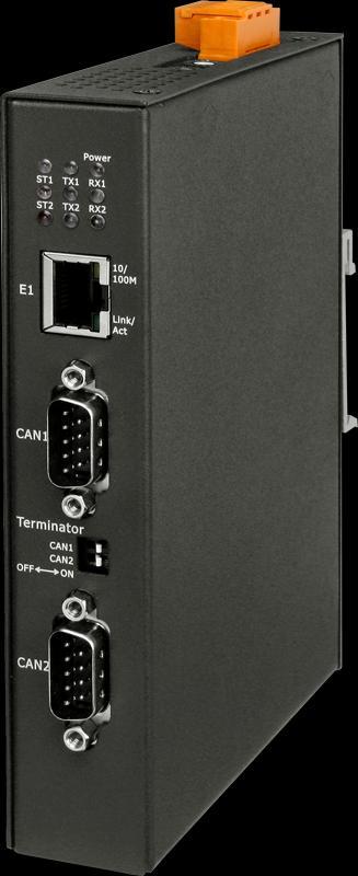
9 2. Getting Started Appearance 1 No. Description LED indicators (7) 2 Ethernet Port with RJ-45 connector 3 CAN1 with 9-pin D-sub male connector 4 Terminator Resistor DIP-switches 5 CAN2 with 9-pin D-sub male connector 6 Power Connector(PWR, GND, F.G.) 7 CAN Bus Baud Rate Rotary Switch 7 6 Wire connections and pin assignments Pin Description 1 N/A 2 CAN Low 3 CAN Ground 4 N/A 5 N/A 6 CAN Ground 7 CAN High 8 N/A 9 N/A Pin Power GND F.G. Power F.G. GND Description Power, +10~+30VDC Power Ground Frame Ground ECAN-240 (Modbus TCP to 2-port CAN Bus Gateway) User Manual, Version Page: 9

 Flashing An error has occurred on CAN 2(*Note) TX1 (Green) Flashing A CAN message was successfully transmitted on CAN1 TX2 (Green) Flashing A CAN message was successfully transmitted on CAN2")
10 2.1. LED Indicator The ECAN-240 module provides seven LED indicators, including indicators for power status and CAN Bus status. The Following is an overview of the purpose and function of each LED indicator together with a description. LED Name LED Status LED Description Power (Red) ON The power of the module is ON ST1 (Red) ON CAN1 Bus is OFF (*Note) Flashing An error has occurred on CAN 1(*Note) ST2 (Red) ON CAN2 Bus is OFF (*Note) Flashing An error has occurred on CAN 2(*Note) TX1 (Green) Flashing A CAN message was successfully transmitted on CAN1 TX2 (Green) Flashing A CAN message was successfully transmitted on CAN2 RX1 (Green) Flashing A CAN message was successfully received on CAN1 RX2 (Green) Flashing A CAN message was successfully received on CAN2 *Note: The CAN Bus will be set to OFF if there are too many faults or if communication is interrupted. In this situation, the ECAN-240 module will automatically restore the Bus and the LED will be turned off. *Note: When CAN bus has some errors or CAN software buffer is overflow, the STx indicator will be flashing. The Ethernet status indicator on ECAN-240 is part of the built-in RJ-45 connector, such as shown in the figure below. LED Name LED Status LED Description ON 100 Mbps 10/100M OFF 10 Mbps or Ethernet disconnected. Link/Act Flashing Communicating ECAN-240 (Modbus TCP to 2-port CAN Bus Gateway) User Manual, Version Page: 10
11 2.2. Rotary Switch The ECAN-240 module provides two rotary switches that are used to change CAN Bus Baud Rate for using the built-in configuration functions. The following is an overview of the purpose and function of each rotary switch position together with a description. CAN2_SW CAN1_SW CAN1_SW CAN2_SW Value Description 0 0 CAN Bus Baud Rate = 10 kbps. 1 1 CAN Bus Baud Rate = 20 kbps. 2 2 CAN Bus Baud Rate = 50 kbps. 3 3 CAN Bus Baud Rate = 80 kbps. 4 4 CAN Bus Baud Rate = 100 kbps. 5 5 CAN Bus Baud Rate = 125 kbps. 6 6 CAN Bus Baud Rate = 250 kbps. 7 7 CAN Bus Baud Rate = 500 kbps. 8 8 CAN Bus Baud Rate = 800 kbps. 9 9 CAN Bus Baud Rate = 1 Mbps. A A User-defined CAN Bus baud rate. B - E Reserved. B Load factory default IP, Mask, Gateway values and not save into EEPROM. C Module self-testing function. Tests the two F CAN Buses and the UDP broadcasting function. D Load all factory default values and saves them to the EEPROM. E Reserved. F Bootloader mode. ECAN-240 (Modbus TCP to 2-port CAN Bus Gateway) User Manual, Version Page: 11
12 2.3. Terminator Resistor In order to minimize the effects of reflection on the CAN Bus, the bus must be terminated using a terminator resistor at each end. According to the specifications given in ISO , each terminator resistor should be 120Ω(or between 108Ω and 132Ω). The bus topology and the positions of these terminator resistors are shown below. The ECAN-240 module includes two CAN ports and terminator resistors are provided for each CAN port. The terminator resistor can be enabled or disabled via the terminator DIP-switches as illustrated in following figure. As indicated in the figure, when the DIP-switch is in the OFF position, the terminator resistor function is disabled. Similarly, when the DIP-switch is in the ON position, the terminator resistor function is enabled. ECAN-240 (Modbus TCP to 2-port CAN Bus Gateway) User Manual, Version Page: 12

13 3. Web Configuration The configuration for the module parameters or communication commands (in Modbus Client mode only) on the ECAN-240 module can be performed via a standard web browser using the embedded web configuration function. The web configuration functions are divided into several categories and includes basic configuration, CAN Bus configuration, Modbus configuration and pair connection configuration. The following is an overview of the process used to configure the ECAN-240 module via the web. The figure below is an illustration of the main screen for web configuration. On the left are the function buttons, including Overview, Basic Settings, CAN Basic Settings, CAN Filter Settings, Specific CAN ID Settings (Modbus TCP Server), Read Command Settings (Modbus TCP Client), Read Command Mapping(Modbus TCP Client), Write Command Settings (Modbus TCP Client), Pair Connection, Reboot, and Logout. Note: The browsers are supported, including IE 8, Chrome, Opera, Firefox(recommended). The influence of Temporary Internet File on IE 8 will lead to work abnormally during using web configuration function. Thus, please change the setting to every visit to the page The IE 11 and Microsoft Edge are not supported. ECAN-240 (Modbus TCP to 2-port CAN Bus Gateway) User Manual, Version Page: 13

14 3.1. Overview The Overview page shows details of the firmware version currently in use on the ECAN-240 module, as illustrated in the figure below. The Overview page also provides a description of each configuration function. The configuration web page can be accessed using either the function button or the link on Overwrite page. As illustrated below, each button is mapped to a link, meaning that there are two ways to access the configuration page. ECAN-240 (Modbus TCP to 2-port CAN Bus Gateway) User Manual, Version Page: 14
 User Manual, Version 1.")
15 3.2. Basic Settings The Basic Configuration section provides the ability to set or adjust basic settings for the ECAN-240 module, including the network, communication, and timeout configuration parameters, etc, as illustrated in the figure below. ECAN-240 (Modbus TCP to 2-port CAN Bus Gateway) User Manual, Version Page: 15
16 The following is an overview of the parameters that can be found on the Basic Configuration page together with a description of each. Parameter Description Module Alias Used to specify recognizable name for the module. MAC Address Used to specify the Ethernet MAC address for the module. Note: the address is set by the manufacturer by default and cannot be modified. IP Address Used to specify the IP address for the module using the IPv4 protocol, and supports class A to E setting. Note: The IPv6 protocol is not supported on the ECAN-240 module. The default IP address is Mask Address Used to specify the standard subnet mask for the module. Note: The default Mask address is Gateway Address Used to specify the Gateway address for the module. Note: The default Gateway address is Authentication Used to specify whether the authentication function is enabled or disabled. If the function is enabled, users attempting to access the web configuration portal will be redirected to the authentication page. Check the checkbox to enable the function. Note: If authentication fails, the web configuration function cannot be used. Login ID Used to specify the authentication login ID. Password Used to specify the authentication password. Enable DHCP Used to enable or disable the DHCP function. Check the checkbox to enable the function. Note : when using this function, the IP, Mask, Gateway settings will be inactive. Client Connection Used to specify the Client Connection Timeout value. When the Timeout ECAN-240 module is set to act as a Server, the value will be used to calculate the timeout value if the Client either malfunctions or if its operation is terminated abnormally. If timeout, the ECAN-240 will be terminated the connection Server Used to specify the Server Reconnection Timeout value. When the Reconnection ECAN-240 module is set to act as a Client, this value will be used to Timeout calculate the timeout value and reconnect the server automatically if the Server either malfunctions or if its operation is terminated abnormally. Communication Used to specify the communication mode to be used. Seven Mode communication modes are provided on the ECAN-240 module. ECAN-240 (Modbus TCP to 2-port CAN Bus Gateway) User Manual, Version Page: 16

17 Details related to the application of each communication mode can be found in Sections 4 to 8. Remote Connection IP Address Modbus Node ID Response Timeout Send CAN Interval Error Response CAN ID Enable Error Response Passively Send CAN Message Save Basic Configuration Used to specify the IP address of a remote device which the ECAN-240 module need to connect. This parameter is used when the ECAN-240 module is acting as a Client. Used to specify the Modbus Node ID when the ECAN-240 module is acting as a Modbus TCP Server. Used to specify a timeout value for Modbus TCP commands. This parameter is used when the ECAN-240 module is operating in Modbus TCP Client mode. Used to specify the CAN message transmission interval. This parameter is used when the ECAN-240 module is operating in Modbus TCP Client mode. Used to specify the CAN ID to be included in a CAN message that is transmitted when the ECAN-240 module receives an error from the Modbus TCP. This function is used when the ECAN-240 module is operating in Modbus TCP Client mode. Used to enable or disable the Error Response function. This function is used in combination with the Error Response CAN ID function and is only used when the ECAN-240 module is operating in Modbus TCP Client mode. Check the checkbox to enable the function. Used to enable or disable the Passively Send CAN Message function. By default, CAN messages are sent actively based on the Send CAN Interval value. This function is only used when the ECAN-240 module is operating in Modbus TCP Client mode. Check the checkbox to enable the function. Used to save the basic configuration to the EEPROM. ECAN-240 (Modbus TCP to 2-port CAN Bus Gateway) User Manual, Version Page: 17

18 3.3. CAN Bus Settings Basic CAN Settings The Basic CAN Settings page is used to configure the user-defined CAN Bus parameters, including CAN Baud Rate, as well as enabling or disabling Listen Only mode. The following is an overview of the parameters that can be found on the Basic CAN Settings page, together with a description of each. Parameter Description Bit Timing Value Used to specify the bit timing value. It is an optimum value. The ECAN-240 module will use this value to calculate a approximate (actual) bit timing. Sample Point (%) Used in the calculation of the CAN Baud Rate. The sample point is located at the specified percentage of the CAN waveform, and defines the error tolerance for the CAN message. Four selection ranges are provided: Actual Bit Timing Value Enable Listen Only Mode Generate Save CAN Configuration Used to specify the real bit timing value after calculating the bit timing parameters. The ECAN-240 module will use this value to communicate with other CAN devices. Used to enable or disable Listen Only mode. Check the checkbox to enable the function. Used to generate a actual bit timing value. Used to save the CAN configuration to the EEPROM. ECAN-240 (Modbus TCP to 2-port CAN Bus Gateway) User Manual, Version Page: 18

19 CAN Filter Settings The CAN ID filter function on the ECAN-240 module allows messages form specific CAN IDs to be received from the CAN network. Five fields can be configured on the CAN Filter Settings page, including the CAN Port, the CAN Specifications, Single/Group selection, and the CAN ID range. The following is an overview of the parameters that can be found on the CAN Filter Settings page, together with a description of each. Parameter Description Add New Rule Used to add a new rule to the CAN Filter table CAN Port Used to specify a CAN port where the CAN ID is to be filtered. CAN Specification Used to specify whether the ID filter is based on either the CAN 2.0A or the CAN 2.0B specification. Single/Group Used to specify whether the filter is based on either a Single or a Group ID. CAN ID Range 1 Used to specify the range of CAN ID values to be filtered. Two fields CAN ID Range 2 are used to set the CAN ID value range. When the Single/Group parameter is set as Single Mode, the values specified in the two range fields will be the same, meaning that a single CAN ID will be filtered. For example, if the CAN ID Range is set as 0x000 to 0x000, it means that only messages from CAN ID 0x000 will be received from the CAN network, and all other messages will be blocked by the module. When the Single/Group parameter is set as Group Mode, the values specified in the two range fields will be the first and last values of a sequential range of CAN IDs. For example, if the CAN ID Range is set as 0x001 to 0x003, it means that only messages from CAN IDs in the range of 0x001 to 0x003 will be received from the CAN network, and all other messages will be blocked by the ECAN-240 (Modbus TCP to 2-port CAN Bus Gateway) User Manual, Version Page: 19
20 Delete Save CAN Configuration module. Used to delete a rule from the CAN Filter table. Used to save the CAN filter configuration to the EEPROM. ECAN-240 (Modbus TCP to 2-port CAN Bus Gateway) User Manual, Version Page: 20

21 3.4. Modbus TCP Server Specific CAN ID Settings The Specific CAN ID Settings function is only used when the ECAN-240 module is operating in Modbus TCP Server mode. In general, the ECAN-240 module will store the I/O data in a ring buffer when a CAN message is received, and then the Modbus address is used to retrieve the I/O data. If a specific CAN ID table is configured, the ECAN-240 module will identify the CAN ID from the specific CAN ID table and then store the IO data in the relevant buffer after finding the same CAN ID from specific CAN ID table. The CAN message in this specific buffer will be overwritten when received the same CAN ID message. Note: About the Modbus address table, please refer to the next section. The following is an overview of the parameters that can be found on the Specific CAN ID Settings page, together with a description of each. Parameter Add New ID CAN Port CAN Specification CAN ID Delete Save CAN Configuration Description Used to add a new CAN ID to the CAN ID table. Used to specify the CAN port that owns this specific CAN ID. Used to specify whether the ID settings are based on the CAN 2.0A or the CAN 2.0B specification. Used to specify the CAN ID value. Used to delete a specific CAN ID from the CAN ID table. Used to save a specific CAN ID configuration to the EEPROM. ECAN-240 (Modbus TCP to 2-port CAN Bus Gateway) User Manual, Version Page: 21

22 3.5. Modbus TCP Client Three kinds of settings for the Modbus TCP Client function are available, including the Read Command Settings, Read Command Mapping, and Write Command Settings, which will be discussed in more detail in section to below Modbus Read Command Settings The Modbus Read Command function is only used when the ECAN-240 module is operation in Modbus TCP Client mode. These commands support Modbus Function codes 0x01 to 0x04. When using Modbus Read Command, the ECAN-240 module will store the returned data in specific memory blocks(the Read Memory Space), and then respond using CAN messages, as illustrated in the following figure. The following is an overview of the parameters that can be found on the Modbus Read Command Settings page, together with a description of each. Parameter Add New Rule CAN Port Slave Node ID Description Used to add a new Modbus Read Command rule to the Modbus Read Command list. Used to specify the CAN port that will be used to send the response with the return value. Used to specify the node ID for the Modbus TCP device. ECAN-240 (Modbus TCP to 2-port CAN Bus Gateway) User Manual, Version Page: 22
23 Function Code Start Address (High) Start Address (Low) Bit/Word Count (High) Bit/Word Count (Low) Delete Save Modbus TCP Client Configuration Used to specify the Modbus Function Code. The ECAN-240 module supports function codes 0x01 to 0x04. Used to specify the high byte of the Modbus start address. Used to specify the low byte of the Modbus start address. Used to specify the high byte of the Bit/Word count. Note: The exact settings for the Bit/Word Count depends on the function code. If the function code is 0x01 or 0x02, this parameter will be set to Bit Count. If the function code is 0x03 or 0x04, it will be set to Word Count. Used to specify the low byte of the Bit/Word count. Note: The exact settings for the Bit/Word Count depends on the function code. If the function code is 0x01 or 0x02, this parameter will be set to Bit Count. If the function code is 0x03 or 0x04, it will be set to Word Count. Used to delete a specific rule from the Modbus Read Command list. Used to save a specific Modbus Read Command to the Flash memory. ECAN-240 (Modbus TCP to 2-port CAN Bus Gateway) User Manual, Version Page: 23

24 Modbus Read Command Mapping The Modbus Read Command Mapping function is only used when the ECAN-240 module is operating in Modbus TCP Client mode. Its major purpose of the function is to map the relationship between the I/O data and the CAN messages. When using the Modbus Read Command Mapping function, the ECAN-240 module will load the I/O data to the CAN data field from the read memory space and then send a CAN message. The following is an overview of the parameters that can be found on the Modbus Read Command Mapping page, together with a description of each. Parameter Add New Rule CAN Port CAN Specification CAN ID Byte Count (High) Memory Start Address Delete Save Modbus TCP Client Configuration Description Used to add a new Read Command Mapping configuration rule to the list. Used to specify the CAN port that will be used to send the response with the return value. Used to specify whether the ID settings are based on the CAN 2.0A or the CAN 2.0B specification. Used to specify the CAN ID value that will be used to send the response. Used to specify the length of the I/O data. Note: this value cannot be greater than 8 bytes, because the maximum data length for a CAN message is 8 bytes. Used to specify the start address of the read memory space, and is used for I/O data and CAN message mapping. Used to delete a specific rule from the Modbus Read Command Mapping configuration list. Save Modbus Read Command Mapping into Flash. Used to save a specific Read Command Mapping configuration to the flash memory ECAN-240 (Modbus TCP to 2-port CAN Bus Gateway) User Manual, Version Page: 24


25 Modbus Write Command Settings The Modbus Write Command Settings function is only used when the ECAN-240 modules in operating in Modbus TCP Client mode. These commands support Modbus Function codes 0x05, 0x06, 0x0F, and 0x10. The Modbus Write Command Settings interface includes a CAN ID field that is used to a map the relationship between specific memory blocks(write memory space) and the CAN messages, as illustrated in the following figure. By using the CAN ID, the ECAN-240 module is able to send a Modbus Write Command containing a variety of data after it receives a CAN message. The following is an overview of the parameters that can be found on the Write Command Settings configuration page, together with a description of each. Parameter Add New Rule CAN Port CAN Specification CAN ID Slave Node ID Function Code Start Address (High) Start Address (Low) Bit/Word Count Description Used to add a new Modbus Write Command rule into to the Modbus Write Command list. Used to specify the CAN port that will be used to receive the CAN data. Used to specify whether the ID settings are based on the CAN 2.0A or the CAN 2.0B specification. Used to specify the CAN message ID that will be used to map the relationship. Used to specify the node ID for the Modbus TCP device. Used to specify the Modbus function code. The ECAN-240 module supports function codes 0x05, 0x06, 0x0F, and 0x10. Used to specify the high byte of the Modbus start address. Used to specify the low byte of the Modbus start address. Used to specify the high byte of the Bit/Word count. ECAN-240 (Modbus TCP to 2-port CAN Bus Gateway) User Manual, Version Page: 25
26 (High) Bit/Word Count (Low) Delete Save Modbus TCP Client Configuration Note: The exact settings for the Bit/Word Count depends on the function code. If the function code is 0x01 or 0x02, this parameter will be set to Bit Count. If the function code is 0x03 or 0x04, it will be set to Word Count. Used to specify the low byte of the Bit/Word count. Note: The exact settings for the Bit/Word Count depends on the function code. If the function code is 0x01 or 0x02, this parameter will be set to Bit Count. If the function code is 0x03 or 0x04, it will be set to Word Count. Used to delete a specific rule from the Modbus Write Command list. Used to save a specific Modbus Write Command to the Flash memory. ECAN-240 (Modbus TCP to 2-port CAN Bus Gateway) User Manual, Version Page: 26

27 3.6. Pair Connection Settings The Pair Connection Settings function is used to configure the router path. As the ECAN-240 module contains two CAN ports, a router table is used to connect two ECAN-240 modules located at different ends of a CAN network. A more detailed illustration of the function will be described in Section 6. The following is an overview of the parameters that can be found on the Pair Connection Settings page, together with a description of each. Parameter Description CAN Port1 to Remote Used to specify the remote CAN port that will be connected to CAN port1 on the ECAN-240 module. CAN Port2 to Remote Used to specify the remote CAN port that will be connected to CAN port2 on the ECAN-240 module. Note: The ECAN-240 module supports two connection methods, one-to-one and one-to-all. For example: Pair Connection Transmission Interval Save Pair Connection Configuration This means that the local CAN port 1 can be connected to either CAN port 1 on the remote device or all CAN ports. Used to specify the transmission interval. Note: While the ECAN-240 module received messages from CAN side until 1400 bytes, and then sent via Ethernet. If not enough 1400 bytes, the ECAN-240 will wait for the transmission interval timeout and then send. Used to save the Pair Connection configuration to the EEPROM. ECAN-240 (Modbus TCP to 2-port CAN Bus Gateway) User Manual, Version Page: 27
28 3.7. Other Functions Reboot Click the Reboot button to reboot the module. After clicking the button, close the browser or the browser tab containing the web configuration page. Logout If the Authentication function is enabled, clicking this button will log the user out from the web configuration page. ECAN-240 (Modbus TCP to 2-port CAN Bus Gateway) User Manual, Version Page: 28

29 4. Modbus TCP Server Applications The Modbus TCP Server function is used to implement communications between a CAN device and a Modbus TCP Client. When the ECAN-240 module is acting as a Modbus TCP Server, the Modbus TCP Client needs to use Modbus commands based on the CAN format in order to access the ECAN-240 module. The ECAN-240 module will then translate these commands into CAN format messages and send them to the CAN networks. Similarly, when a CAN format message is received from the CAN network, the ECAN-240 translates the message into Modbus format, which can then be accessed using a Modbus command. As illustrated below, the data pool can be considered as a ring buffer that can store up to 200 records. If this maximum is exceeded, the ECAN-240 module will overwrite the oldest record. The ECAN-240 module also provides an additional buffer that can be used to store messages based on specific CAN ID. The maximum is 100 records can be stored. The functionality of this buffer is slightly different in that. The message in this buffer will be overwritten based on the specific CAN ID. ECAN-240 (Modbus TCP to 2-port CAN Bus Gateway) User Manual, Version Page: 29
30 The ECAN-240 module supports Modbus function codes 0x03, 0x04, 0x06, and 0x10, as indicated in the table below. Function Code Function Name Description 3 (03 Hex) Read Output Register Used to read multiple output registers when sending a CAN message. 4 (04 Hex) Read Input Register Used to read multiple input registers when receiving a CAN message 6 (06 Hex) Write Output Register Used to write single output registers for sending a CAN message 16 (10 Hex) Write Multiple Registers Used to write multiple registers for sending a CAN message ECAN-240 (Modbus TCP to 2-port CAN Bus Gateway) User Manual, Version Page: 30


31 4.1. Modbus Address Mapping The memory on the ECAN-240 module is divided into two parts, depending on the purpose, and includes the Input Register and the Output Register to match the needs of Modbus TCP Server applications Input Register The major purpose of the Input Register is used for reading CAN messages. Since the ECAN-240 contains two CAN ports, the Input Register is divided to two sections, one for each CAN port. The ECAN-240 module also provides the ability to read the status of the module using Modbus commands. The following figures provide an overview of the address allocation for the Input Register. ECAN-240 (Modbus TCP to 2-port CAN Bus Gateway) User Manual, Version Page: 31
32 CAN1/CAN2 Rx memory addresses Protocol Addresses (Base 0) PLC Addresses (Base 1) Word Count Description Decimal rule (CAN1) ~ ~ CAN1 Rx Message # ~ ~ CAN1 Rx Message # ~ ~ CAN1 Rx Message # ~ ~ CAN1 Rx Message #200 Decimal rule (CAN2) ~ ~ CAN2 Rx Message # ~ ~ CAN2 Rx Message # ~ ~ CAN2 Rx Message # ~ ~ CAN2 Rx Message #200 Addresses for specific CAN1/CAN2 Rx messages Protocol Addresses (Base 0) PLC Addresses (Base 1) Word Count Description Decimal rule (CAN1) ~ ~ CAN1 specific Rx Message # ~ ~ CAN1 specific Rx Message # ~ ~ CAN1 specific Rx Message # ~ ~ CAN1 specific Rx Message #100 Decimal rule (CAN2) ~ ~ CAN2 specific Rx Message # ~ ~ CAN2 specific Rx Message # ~ ~ CAN2 specific Rx Message # ~ ~ CAN2 specific Rx Message #100 ECAN-240 (Modbus TCP to 2-port CAN Bus Gateway) User Manual, Version Page: 32
33 Module status addresses Protocol Addresses (Base 0) PLC Addresses (Base 1) Word Count Description Decimal rule (CAN1) CAN1 Rx message count CAN1 Baud Rate configuration ~ ~ User-defined Baud Rate configuration for CAN CAN1 status register CAN1 error count CAN1 overflow CAN2 Rx message count CAN2 Baud Rate configuration ~ ~ User-defined Baud Rate configuration for CAN CAN2 status register CAN2 error count CAN2 overflow Ethernet status Firmware version ~ ~ Module Name ~ ~ Manufacturer CAN status register Bit Number Description 7 Bus Status (0: Bus-On, 1: Bus-Off). 6 Error Status (0: no error, 1: error). 5 Transmit Status (0: idle, 1: transmit). 4 Receive Status (0: idle, 1: receive). 3 Transmit Complete Status (0: incomplete, 1: complete). 2 Transmit Buffer Status (0: locked, 1: released). 1 Data Overrun Status (0: absent, 1: overrun). 0 Receive Buffer Status (0: empty, 1: full). ECAN-240 (Modbus TCP to 2-port CAN Bus Gateway) User Manual, Version Page: 33
34 Ethernet status Bit Number Description M Full Duplex (0: non-used, 1: used) M Half Duplex (0: non-used, 1: used) M Full Duplex (0: non-used, 1: used) M Half Duplex (0: non-used, 1: used) Reserved 5 Auto-negotiation Complete (0: incomplete, 1: complete) 3 4 Reserved 2 Link Status (0: Link-Off, 1: Link-On) 0-1 Reserved ECAN-240 (Modbus TCP to 2-port CAN Bus Gateway) User Manual, Version Page: 34

35 Output Register The major purpose of the output register is for writing CAN messages. Since the ECAN-240 module contains two CAN ports, the Output Register is divided to two sections, one for each CAN port. ECAN-240 also provides the ability to control the module using Modbus commands. The following figures provide an overview of the address allocation for the Output Register. CAN1/CAN2 Tx message addresses Protocol Addresses PLC Addresses (Base 0) (Base 1) Decimal rule (CAN1) Word Description Count ~ ~ CAN1 Tx Message Decimal rule (CAN2) ~ ~ CAN2 Tx Message Addresses for specific settings commands Protocol Addresses (Base 0) PLC Addresses (Base 1) Word Count Description Decimal rule (CAN1) ~ ~ Modbus Command (Configuration) The Modbus Command (Configuration) includes the Reboot Module and Reset CAN bus functions. ECAN-240 (Modbus TCP to 2-port CAN Bus Gateway) User Manual, Version Page: 35
36 Reboot Module This function is used to reboot the ECAN-240 module using Modbus command. After sending the request command, the module will respond with a message indicating that the request was successful. Request command: Field Name Size Valid Value Range Example Hexadecimal rule Node ID 1 byte 0x01 to 0xF7 0x01 Function Code 1 byte 0x10 0x10 Start Address 2 bytes 0x0100 0x0100 Word Count 2 bytes 0x0002 0x0002 Byte Count 1 byte 0x04 0x04 Data-1 2 bytes 0x0001 0x0001 Data-2 2 bytes 0x0001 0x0001 Response: Field Name Size Valid Value Range Example Hexadecimal rule Node ID 1 byte 0x01 to 0xF7 0x01 Function Code 1 byte 0x10 0x10 Start Address 2 bytes 0x0100 0x0100 Word Count 2 bytes 0x0002 0x0002 Reset CAN bus This function is used to reset the CAN bus via a Modbus command. After sending the request command, the module will respond with a message indicating that the request was successful. Request command: Field Name Size Valid Value Range Example Hexadecimal rule Node ID 1 byte 0x01~0xF7 0x01 Function Code 1 byte 0x10 0x10 Start Address 2 bytes 0x0100 0x0100 Word Count 2 bytes 0x0002 0x0002 Byte Count 1 byte 0x04 0x04 Data-1 2 bytes 0x0001 0x0001 Data-2 2 bytes 0x0002 0x0001 ECAN-240 (Modbus TCP to 2-port CAN Bus Gateway) User Manual, Version Page: 36
37 Response: Field Name Size Valid Value Range Example Hexadecimal rule Node ID 1 byte 0x01 to 0xF7 0x01 Function Code 1 byte 0x10 0x10 Start Address 2 bytes 0x0100 0x0100 Word Count 2 bytes 0x0002 0x0002 Note: This command will clear CAN error status and software buffer overflow status. ECAN-240 (Modbus TCP to 2-port CAN Bus Gateway) User Manual, Version Page: 37
38 4.2. Structure of CAN message in Modbus commands In order to enable data exchange between the CAN bus and Modbus, the ECAN-240 module provides CAN data format in a standard Modbus command. The CAN data format in Modbus commands is divided to two parts, Read CAN message format and Write CAN message format. Read Command Format: Word Number Description 1 Bit 15: 0 = valid data, 1 = invalid data Bit 6~14: Reserved Bit 5: CAN Specification, 0 = 2.0A, 1 = 2.0B Bit 4: RTR, 0 = No, 1 = Yes Bit s 0-3: Data length, value = Most significant two bytes of the CAN identifier. (Big-endian) 3 Least significant two bytes of the CAN identifier. (Big-endian) 4 The Data 1 and Data 2 elements from the CAN data field. 5 The Data 3 and Data 4 elements from the CAN data field. 6 The Data 5 and Data 6 elements from the CAN data field. 7 The Data 7 and Data 8 elements from the CAN data field. 8 Most significant two bytes of the RX timestamp message. (Big-endian) 9 Least significant two bytes of the RX timestamp message. (Big-endian) Write Command Format: Word Number Description 1 Bit 6-15: Reserved Bit 5: CAN Specification, 0 = CAN 2.0A, 1 = CAN 2.0B Bit 4: RTR, 0 = No, 1 = Yes Bit 0-3: Data length, value = Most significant two bytes of the CAN Identifier. (Big-endian) 3 Least significant two bytes of the CAN Identifier. (Big-endian) 4 The Data 1 and Data 2 elements from the CAN data field. 5 The Data 3 and Data 4 elements from the CAN data field. 6 The Data 5 and Data 6 elements from the CAN data field. 7 The Data 7 and Data 8 elements from the CAN data field. ECAN-240 (Modbus TCP to 2-port CAN Bus Gateway) User Manual, Version Page: 38

39 4.3. Modbus Command Examples The following is an illustration of how to use Modbus commands to read or write CAN messages and configure the ECAN-240 module Reading a CAN message via a Modbus command Refer to the figure for details of how to use function code 0x04 to read a single CAN message. ECAN-240 (Modbus TCP to 2-port CAN Bus Gateway) User Manual, Version Page: 39
 User Manual, Version 1.0.0 Page: 40")
40 Refer to the figure for details of how to use function code 0x04 to read two CAN messages. ECAN-240 (Modbus TCP to 2-port CAN Bus Gateway) User Manual, Version Page: 40

41 Reading a CAN message containing a specific CAN ID via a Modbus command Refer to the figure for details of how to use function code 0x04 to read a single CAN message that contains a specific CAN ID. ECAN-240 (Modbus TCP to 2-port CAN Bus Gateway) User Manual, Version Page: 41
 User Manual, Version 1.0.0 Page: 42")
42 Reading a CAN message that has been sent via a Modbus command Refer to the figure for details of how to use function code 0x03 to read a CAN message that has been sent via a Modbus command. ECAN-240 (Modbus TCP to 2-port CAN Bus Gateway) User Manual, Version Page: 42
 User Manual, Version 1.0.0 Page: 43")
43 Reading the status of a module via a Modbus command Refer to the figure for details of how to use function code 0x04 to read the status of a module. ECAN-240 (Modbus TCP to 2-port CAN Bus Gateway) User Manual, Version Page: 43


44 Writing a CAN message via a Modbus command There are two ways to write a CAN message, including using function codes 0x06 and 0x10. Using function code 0x06: The following is a step-by-step illustration of how to send a CAN message via function code 0x06. ECAN-240 (Modbus TCP to 2-port CAN Bus Gateway) User Manual, Version Page: 44
45 ECAN-240 (Modbus TCP to 2-port CAN Bus Gateway) User Manual, Version Page: 45

")
46 Using function code 0x10: Refer to figure for details of how to use function code 0x10 to write a CAN message. ECAN-240 (Modbus TCP to 2-port CAN Bus Gateway) User Manual, Version Page: 46
47 4.4. Modbus Exception Codes The following is an overview of the Modbus Exception codes that are supported by the ECAN-240 module. Code Description Possible causes & solutions 1 Illegal function The function code is not supported by the ECAN-240 module. 2 Illegal Data Address The data address does not exist on the ECAN-240 module. 3 Illegal Data Value The number of registers or the byte count value is not valid, or no CAN message details are stored in the Normal CAN Message field on the ECAN-240 module. 6 Slave Device Busy A transmission buffer overrun has occurred. The message should be retransmitted at a later time once the status of the module has returned to normal. ECAN-240 (Modbus TCP to 2-port CAN Bus Gateway) User Manual, Version Page: 47

48 5. Modbus TCP Client Applications The Modbus TCP Client function is used to implement communications between a CAN Bus and a Modbus TCP Server. When the ECAN-240 module is acting as a Modbus TCP Client, it can access the Modbus TCP Server via the command configuration. When the ECAN-240 module receives I/O data, it will forward it to the remote CAN devices for analysis, control, or other operations. Once configured, the ECAN-240 module is also able to access the Modbus TCP Server via a CAN message. ECAN-240 (Modbus TCP to 2-port CAN Bus Gateway) User Manual, Version Page: 48
49 5.1. Supported Modbus Function Codes The Modbus TCP Client function supports Modbus function codes 0x01, 0x02, 0x03, 0x04, 0x05, 0x06, 0x0F, and 0x10, as indicated in the table below. Modbus Command Modbus Read Command Modbus Write Command Function Code Function Name Description 1 (01 Hex) Read Coil Status Used to read the status of a coil from a Modbus TCP Server device. 2 (02 Hex) Read Input Status Used to read the status of the input from a Modbus TCP Server device. 3 (03 Hex) Read Holding Registers Used to read Holding Registers from a Modbus TCP Server device. 4 (04 Hex) Read Input Registers Used to read the registers of the input from a Modbus TCP Server device. 5 (05 Hex) Write Single Coil Used to write to a single coil on a Modbus TCP Server device. 6 (06 Hex) Write Signal Register Used to write to a single register on a Modbus TCP Server device. 15 (0F Hex) Write Multiple Coil Used to write to multiple coils on a Modbus TCP Server device. 16 (10 Hex) Write Multiple Registers Used to write to multiple registers on a Modbus TCP Server device. ECAN-240 (Modbus TCP to 2-port CAN Bus Gateway) User Manual, Version Page: 49

50 5.2. I/O Memory Size The ECAN-240 module provides a memory block that can be used for data exchange via Modbus TCP Client function. Each CAN port provides a total of 2048 bytes of memory space for transmission and reception, where the available space is 1024 bytes for each. For more information related to the operation of the transmission and reception memory blocks, refer to Sections 3.5. ECAN-240 (Modbus TCP to 2-port CAN Bus Gateway) User Manual, Version Page: 50
51 5.3. Error Response The ECAN-240 Module allows error response messages over CAN Bus via error response settings. The Error Response CAN ID is used to specify the CAN ID of the error response messages. Once the error response function is enabled, a CAN message will be returned whenn the ECAN-240 encounters a Modbus error. The following describes the format and definition of the CAN error response message. CAN Error Response Message Format CAN ID Length Byte 0 Bytes 1-3 Bytes 4-6 Byte7 Error Response 8 Identifier Code Reserved Modbus Reserved CAN ID Exception The Identifier Code in Data Byte0 is divided into four types Identifier Code 0x00 0x01 0x02 0x03 Description Reserved This code indicates that the current Modbus command has been completely transmitted, but the ECAN-240 module has received the wrong Node ID command. This code indicates that the current Modbus command has been completely transmitted, but the ECAN-240 module has not received any response command. This code indicates that the current Modbus command has been completely transmitted, but the ECAN-240 module has received a Modbus Exception command. Data Bytes 4 to 7 indicate the Modbus Exception message, which includes the Slave Node ID, the Exception Function Code, and the Exception Code. If the Identifier code is 0x03, this message will be shown in the CAN error response message. Otherwise, these data value will be 0x00. ECAN-240 (Modbus TCP to 2-port CAN Bus Gateway) User Manual, Version Page: 51
52 Modbus Exceptions Byte4 Byte5 Byte6 Byte7 Slave Node ID Exception Function Code Exception Code Reserved Relationship between the Function Code and Exception Function Code Function Code (Hex) 0x01 0x02 0x03 0x04 0x05 0x06 0x0F 0x10 Exception Function Code (Hex) 0x81 0x82 0x83 0x84 0x85 0x86 0x8F 0x90 Modbus Exception Code For more information related to Modbus Exception Code, refer to the Modbus protocol specifications. ECAN-240 (Modbus TCP to 2-port CAN Bus Gateway) User Manual, Version Page: 52
.")

53 6. Pair Connection Applications The pair connection function is used to implement communication between two ends of CAN network. CAN Network #1 can communicate with CAN Network #3 or CAN Network #4 using pair connection configuration (for details of the router table, refer to Section 3.6). Similarly, CAN Network #2 can also communicate with CAN Network #3 or CAN Network #4 in the same manner. The pair connection function on the ECAN-240 module is implemented via either the TCP or the UDP protocol. When using the TCP protocol, the application architecture will be one-to-one, as illustrated in the application diagram below. When using the UDP protocol, the application architecture will be either one-to-one or one-to-many (UDP broadcast), as illustrated in the application diagram below. ECAN-240 (Modbus TCP to 2-port CAN Bus Gateway) User Manual, Version Page: 53

54 Note: When using UPD protocol, be aware that some routers will block the transmission of UPD packets to the Internet. The Transparent option is to see as a half-pair connections. The TCP/UDP packet is in CAN format and contains the CAN ID. TCP uses port and UDP uses port This is useful because it allows custom TCP/UDP programs to be developed that can directly access the ECAN-240 module for specific applications. ECAN-240 (Modbus TCP to 2-port CAN Bus Gateway) User Manual, Version Page: 54

55 7. Listen Only Application The Listen Only function is used for listening to CAN Bus communications between two CAN networks. After enabling the Listen Only function and rebooting the module, the CAN Bus on the ECAN-240 module will be set to Listen Only mode, meaning that the ECAN-240 module will not be able to send any messages to the CAN Bus. On the Ethernet side of the connection, the ECAN-240 module acts as a Modbus TCP Server and can be accessed using Modbus TCP commands. ECAN-240 (Modbus TCP to 2-port CAN Bus Gateway) User Manual, Version Page: 55

56 8. Bridge Mode Applications Bridge Mode is a special function that allows two CAN networks to communicate with each other via the ECAN-240 protocols. At this time, the ECAN-240 module acts as a Modbus TCP Server and CAN messages can be transmitted between two CAN modules using Modbus TCP commands. ECAN-240 (Modbus TCP to 2-port CAN Bus Gateway) User Manual, Version Page: 56
 and the latest version of the Firmware Updata utility, FW_Update_CAN_vX.XX.exe (where X denotes the utility version), are available from the FTP link below.")
57 Appendix A Firmware Update The firmware on the ECAN-240 module can be updated via CAN devices produced by ICP DAS. The latest firmware file ( *.fw ) and the latest version of the Firmware Updata utility, FW_Update_CAN_vX.XX.exe (where X denotes the utility version), are available from the FTP link below. A notification will not be sent when a new version is released. ftp://ftp.icpdas.com/pub/cd/fieldbus_cd/can/gateway/ecan-240/firmware ftp://ftp.icpdas.com/pub/cd/fieldbus_cd/can/gateway/ecan-240/software/update_tool Follow the process described below to update the firmware for the ECAN-240 module using the ICP DAS Firmware Update utility. Step 1: Move the two rotary switches to the 0xF position (Bootloader mode) and reboot the module. Once the ECAN-240 module has rebooted, all the LEDs on the module will be flashing. Step 2: Run the Firmware Update utility, FW_Update_CAN_vX.XX.exe (where X denotes the utility version). [1] CAN devices: The firmware on the ECAN-240 module can be updated by using ICP DAS CAN products indicated below and Firmware Update utility. (1) RS232 to CAN : I-7530(A). (2) Ethernet to CAN: I-7540D. (3) USB to CAN: I-7565, I-7565-H1, and I-7565-H2. (4) CAN Card: PISO-CM100(U), PISO-/PCM-/PEX-CAN200 and CAN400. ECAN-240 (Modbus TCP to 2-port CAN Bus Gateway) User Manual, Version Page: 57
 Set the CAN_Port number. (4) Connect to CAN Port 1 of the ECAN-240 module. [2] Download the Firmware: (1) Click the Browser button to select the location of the firmware file.")
58 Before updating the firmware, the following parameters needs to be set on the utility. (1) Select the CAN hardware device. (2) Set the Dev_Port or Board_ID (for CAN cards only). (3) Set the CAN_Port number. (4) Connect to CAN Port 1 of the ECAN-240 module. [2] Download the Firmware: (1) Click the Browser button to select the location of the firmware file. The name of the firmware file will be ECAN-240_vXXX.fw (where X denotes the firmware version). (2) Click the Start Firmware Download button to being the firmware update process. While the firmware is being updated, a progress bar will be displayed in the utility to indicate the status of the update process. Once the firmware has been successfully updated, a notification will be displayed. ECAN-240 (Modbus TCP to 2-port CAN Bus Gateway) User Manual, Version Page: 58
I-7550E PROFIBUS/Ethernet Converter. User's Manual
 I-7550E PROFIBUS/Ethernet Converter User's Manual High Quality, Industrial Data Acquisition, and Control Products I-7550E PROFIBUS/Ethernet Converter User Manual (Version 100, June/2014) PAGE: 1 Warranty
tsh-700 Series User Manual
 tsh-700 Series User Manual Tiny Serial Port Sharer Aug. 2017 Ver. 1.6 WARRANTY All products manufactured by ICP DAS are warranted against defective materials for a period of one year from the date of delivery
GW-7238D J1939 to Modbus TCP Server / RTU Slave Gateway
 GW-7238D J1939 to Modbus TCP Server / RTU Slave Gateway User s Manual www.icpdas.com 1 Warranty All products manufactured by ICP DAS are under warranty regarding defective materials for a period of one
NCOM SERIAL DEVICE SERVER 4XX SERIES USER S MANUAL
 NCOM SERIAL DEVICE SERVER 4XX SERIES USER S MANUAL 2017-07-07 Edition Titan Electronics Inc. Web: www.titan.tw Contents 1. INTRODUCTION... 4 1.1 Key Features... 5 1.2 Specifications... 6 2. PANEL LAYOUT
Motortronics VirtualSCADA VS2-MT Communication Gateway VS2-MT User Manual Revision
 Motortronics VirtualSCADA VS2-MT Communication Gateway VS2-MT User Manual Revision 1.03.00 Motortronics / Phasetronics 1600 Sunshine Drive Clearwater, Florida 33765 Tel: 727-573-1819 Fax: 727-573-1803
The I-7530A-MR Modbus RTU to CAN Converter
 The I-7530A-MR Modbus RTU to CAN Converter User s Manual Warranty All products manufactured by ICP DAS are under warranty regarding defective materials for a period of one year from the date of delivery
NCOM SERIAL DEVICE SERVER 1XX SERIES USER S MANUAL
 NCOM SERIAL DEVICE SERVER 1XX SERIES USER S MANUAL 2017-07-07 Edition Titan Electronics Inc. Web: www.titan.tw Contents 1. INTRODUCTION... 4 1.1 Key Features... 5 1.2 Specifications... 6 2. PANEL LAYOUT
i-7550 PROFIBUS to RS-232/422/485 Converter User's Manual High Quality, Industrial Data Acquisition, and Control Products
 i-7550 PROFIBUS to RS-232/422/485 Converter User's Manual High Quality, Industrial Data Acquisition, and Control Products i-7550 PROFIBUS to RS-232/422/485 Converter User's Manual (Version 1.01) PAGE:1
The I-7530A RS-232/485/422 to CAN Converter
 The I-7530A RS-232/485/422 to CAN Converter User s Manual Warranty All products manufactured by ICP DAS are under warranty regarding defective materials for a period of one year from the date of delivery
DL-10. User Manual. RS-485 Remote Temperature and Humidity. English Ver. 1.0, Jul. 2017
 DL-10 User Manual RS-485 Remote Temperature and Humidity English Ver. 1.0, Jul. 2017 WARRANTY All products manufactured by ICP DAS are warranted against defective materials for a period of one year from
GW-7228 J1939/Modbus RTU Slave Gateway
 GW-7228 J1939/Modbus RTU Slave Gateway User s Manual www.icpdas.com GW-7228 J1939/Modbus RTU Slave Gateway User s Manual (Ver 1.2, May/2011) ------------- 1 Warranty All products manufactured by ICP DAS
Industrial Serial Device Server
 1. Quick Start Guide This quick start guide describes how to install and use the Industrial Serial Device Server. Capable of operating at temperature extremes of -10 C to +60 C, this is the Serial Device
I-7570 Serial To HART Converter
 I-7570 Serial To HART Converter User s Manual Warranty All products manufactured by ICP DAS are under warranty regarding defective materials for a period of one year from the date of delivery to the original
GW-7472 / GW EtherNet/IP to Modbus RTU/TCP Gateway User Manual
 GW-7472 / GW-7473 EtherNet/IP to Modbus RTU/TCP Gateway User Manual Warranty All products manufactured by ICP DAS are under warranty regarding defective materials for a period of one year, starting from
Serial to Ethernet Converter
 Serial to Ethernet Converter User s Manual Version 1.1 2004 Infosystem Technology Corporation Disclaimers The information in this manual has been carefully checked and is believed to be accurate. Infosystem
tgw-700 Series User Manual
 tgw-700 Series User Manual Ver. 2.2, Nov. 2017 WARRANTY All products manufactured by ICP DAS are warranted against defective materials for a period of one year from the date of delivery to the original
GW-7553-CPM PROFIBUS/CANopen GATEWAY. User's Manual
 GW-7553-CPM PROFIBUS/CANopen GATEWAY User's Manual High Quality, Industrial Data Acquisition, and Control Products GW-7553-CPM PROFIBUS/CANopen GATEWAY User Manual (Version 1.00, Apr/2016) PAGE: 1 Warranty
WLAN Products 2.1 Overview P WLAN Remote Maintenance Device P WLAN Converter P Applications P2-4-1
 WLAN Products.1 Overview P-1-1. WLAN Remote Maintenance Device P--1.3 WLAN Converter P-3-1.4 Applications P-4-1 Overview.1. Overview WLAN Products Overview 1 WLAN (Wireless Local Area Network) links devices
3-7 Tiny Serial-to-Ethernet Device Server & Modbus Gateway
 Tiny Serial-to-Ethernet Device Server & Modbus Gateway - Tiny Serial-to-Ethernet Device Server & Modbus Gateway tds-00 Series tds-12 tds-00 series tdsm-12 Tiny Serial-to-Ethernet Device Server Features
Winsonic MODBUS Remote IO user manual Rev. 1.0
 Winsonic MODBUS Remote IO user manual Rev. 1.0 Model: LEGAL NOTICE Warranty All products manufactured by Winsonic are under warranty regarding defective materials for a period of one year, beginning from
FR-2057iT. 16-channel Sink Type Isolated Output Module With Isolated Communication line. User Manual
 FR-2057iT 16-channel Sink Type Isolated Output Module With Isolated Communication line User Manual Warranty All products manufactured by ICP DAS are warranted against defective materials for a period of
tgw-700 Series User Manual
 tgw-700 Series User Manual Warranty All products manufactured by ICP DAS are warranted against defective materials for a period of one year from the date of delivery to the original purchaser. Warning
ZigBee Converter User s Manual
 ZigBee Converter User s Manual Warranty All products manufactured by ICP DAS are warranted against defective materials for a period of one year from the date of delivery to the original purchaser. Warning
Warranty. Warning. Copyright. Contact Us
 M-6026U-32 16-channel Universal Input and 16-channel Universal Output Version: 1.0.0 Date: Dec. 2017 Edited by Horse Chien M-6026U-32 User Manual Version 1.0.0 Dec. 2017-1 - Warranty All products manufactured
SERIAL TO ETHERNET CONVERTER E-P User Manual
 SERIAL TO ETHERNET CONVERTER E-P132-100 User Manual 1 Table of Contents Introduction... 4 Overview.. 5 Package Checklist 6 Block Diagram 7 Product Features...8 Product Specifications 9 Converter Description
HART 710. User s Manual Version HART-710 User Manual (Version 1.00, July/2010) PAGE: 1
 PAGE: 1") TM HART 710 User s Manual Version 1.00 HART-710 User Manual (Version 1.00, July/2010) PAGE: 1 Warranty All products manufactured by ICP DAS are under warranty regarding defective materials for a period
TM HART 710 User s Manual Version 1.00 HART-710 User Manual (Version 1.00, July/2010) PAGE: 1 Warranty All products manufactured by ICP DAS are under warranty regarding defective materials for a period
EGW1-IA3-MB User s Manual
 www.exemys.com Rev. 0 1 Products are in constant evolution to satisfy our customer needs. For that reason, the specifications and capabilities are subject to change without prior notice. Updated information
tds-700 Series User Manual
 tds-700 Series User Manual Ver.1.9.1 Tiny Serial-to-Ethernet Device Server WARRANTY All products manufactured by ICP DAS are warranted against defective materials for a period of one year from the date
IPM-01 / IPM-01H MODBUS TCP/RTU Bridge User Guide
 VxI Power Ltd. IPM-01 / IPM-01H MODBUS TCP/RTU Bridge User Guide 01/12/2015 Document Number: 14970-020A Issue Number: 2 Contents 1.0 Device Overview... 2 2.0 Getting Started... 3 2.1 Connecting the Device...
MODEL: GR8-EM. Communication Adaptor GR8 Series
 Communication Adaptor GR8 Series Ethernet/RS-485 Adaptor (Modbus use) Functions & Features Bidirectional protocol converter for Modbus/TCP (Ethernet) and Modbus RTU (RS-485) Fast response time thanks to
The UART to CAN Bus Converter
 The UART to CAN Bus Converter (I-7530, I-7530T, I-7530-FT, I-7530A, I-7565, tm-7530) User s Manual Warranty All products manufactured by ICP DAS are under warranty regarding defective materials for a period
ET-2200 Series Ethernet I/O Modules User Manual
 ET-2200 Series Ethernet I/O Modules User Manual Ethernet I/O Module Ver. 1.3.0, Jun. 2018 WARRANTY All products manufactured by ICP DAS are warranted against defective materials for a period of one year
Embedded Modbus TCP Module GS11-MT. User Manual REV 1.1. SST Automation.
 Embedded Modbus TCP Module GS11-MT User Manual REV 1.1 SST Automation E-mail: SUPPORT@SSTCOMM.COM WWW.SSTCOMM.COM Catalog 1 About the Embedded Module... 4 1.1 General...4 1.2 Features... 4 1.3 Specifications...4
BACnet/IP to BACnet MS/TP Router
 BACnet/IP to BACnet MS/TP Router Features Compact Size Routes between BACnet /IP and BACnet MS/TP networks 10/100Mbps Ethernet Auto-MDIX port Optically isolated MS/TP communications port MS/TP baud rates:
Document Name: User Manual for SC10MK, Modbus RTU to Modbus TCP Converter
 Document Name: User Manual for SC10MK, Modbus RTU to Modbus TCP Converter Login for the first time, please use http://192.168.1.100 To key in user name and password is for identifying authorization. Default
Infosystem. User Manual. Version 1.0. Serial to Ethernet Converter with 3 sockets. Infosystem Technology Corporation, Ltd.
 WS-100B Serial to Ethernet Converter with 3 sockets Copyright 2005 Infosystem Technology Corporation, Ltd. No. 45, Lane 167, Dongnan St. Hsinchu, Taiwan 300, R.O.C. TEL: +886-3-562-7187 FAX: +886-3-561-1435
INDEX. Document Name : User Manual for SC10EJ Serial to Ethernet Converter
 Document Name : User Manual for SC10EJ Serial to Ethernet Converter Page 1 of 10 INDEX 1. Technical Specifications 1 2. Modes of Operation 1 3. Configuring the SC10 EJ : Through Serial Port 2 a. Configuring
SK CU4-EIP-C Part number:
 SK CU4-EIP-C Part number: 275 271 519 EtherNet/IP Internal Bus Interface The bus interface may only be installed and commissioned by qualified electricians. An electrician is a person who, because of their
GW-7662 User Manual. Version 1.00, Jan Written by Ryan Lin
 GW-7662 User Manual Version 1.00, Jan. 2015 Written by Ryan Lin Warranty All products manufactured by ICP DAS are under warranty regarding defective materials for a period of one year, beginning from the
HRT-710. User s Manual Version HRT-710 User Manual (Version 1.23, Dec/2012) PAGE: 1
 PAGE: 1") TM HRT-710 User s Manual Version 1.23 HRT-710 User Manual (Version 1.23, Dec/2012) PAGE: 1 Warranty All products manufactured by ICP DAS are under warranty regarding defective materials for a period of
TM HRT-710 User s Manual Version 1.23 HRT-710 User Manual (Version 1.23, Dec/2012) PAGE: 1 Warranty All products manufactured by ICP DAS are under warranty regarding defective materials for a period of
tm-752n Series User Manual
 tm-752n Series User Manual Tiny Addressable Serial Converter Ver. 1.1.1/ Aug. 2014 SUPPORTS Module includes tm-7521 and tm-7522. WARRANTY All products manufactured by ICP DAS are warranted against defective
NET101. RS232 / RS422 / RS485 to Ethernet Converter. User s Manual. Version 1.2
 NET101 RS232 / RS422 / RS485 to Ethernet Converter User s Manual Version 1.2 Copyright Information Copyright 2004-2005, Mega System Technologies, Inc. All rights reserved. Reproduction without permission
J1939/Modbus Slave Gateway FAQ
 J1939/Modbus Slave Gateway FAQ Version 1.0 (For GW-7228/GW-7238D) ICP DAS Co., Ltd. Table of Contents J1939/Modbus Slave Gateway FAQ v1.0 Q01 : How to solve CAN Bus Transmission Fail problem?... 2 Q02
USR-TCP User Manual
 USR-TCP232-306 User Manual File Version: V1.0.1.01 1 Contents USR-TCP232-306 User Manual...1 Features...3 1. Get Start...4 1.1. Application Diagram...4 1.2. Hardware Design...5 1.2.1. Hardware Dimensions...5
MSD-SRF2XM Multi-port RS-232 to Ethernet Data Gateway User Manual
 MSD-SRF2XM Multi-port RS-232 to Ethernet Data Gateway User Manual The MSD-SRF2X Dual port RS-232 to Ethernet data gateway will address the need to add 2 RS-232C devices to an IP-based Ethernet LAN on your
BAS Router BACnet Multi-Network Router
 BAS Router BACnet Multi-Network Router The BAS Router provides stand-alone routing between BACnet networks such as BACnet/IP, BACnet Ethernet, and BACnet MS/TP thereby allowing the system integrator to
Hardened Web-Smart High Power PoE Ethernet Switch
 Quick Start Guide This quick start guide describes how to install and use the Hardened Web-Smart High Power PoE (Power over Ethernet) Ethernet Switch. This is the switch of choice for harsh environments
NetBiter Serial Server User Manual
 User Manual IntelliCom Innovation AB Linjegatan 3D SE-302 50 Halmstad SWEDEN Phone +46 35 18 21 70 Fax +46 35 17 29 09 email info@intellicom.se web www.intellicom.se Revision List Revision Date Author
8520/8520R. User Manual
 /R User Manual Warranty All products manufactured by SuperLogics are warranted against defective materials for a period of one year from the date of delivery to the original purchaser. Disclaimer SuperLogics
WM-120. Serial to Ethernet Module. Serial to Ethernet Module. User Manual. Version 1.0. Infosystem Technology Corporation, Ltd.
 W M - 1 2 0 User Manual Version 1.0 Infosystem Technology Corporation, Ltd. Index 1. Disclaimers... 1. A. Warranty... 2. B. Trademark... 2. 2. Product Information... 3. A. Introduction... 3. B. Features...
WIZ220IO / WIZ220IO-EVB User s Manual (Ver. 1.0)
") [ 텍스트입력 ] WIZ0IO / WIZ0IO-EVB User s Manual (Ver. 1.0) 010 WIZnet Inc. All Rights Reserved. For more information, visit our website at www.wiznet.co.kr Document History Information Revision Data Description
[ 텍스트입력 ] WIZ0IO / WIZ0IO-EVB User s Manual (Ver. 1.0) 010 WIZnet Inc. All Rights Reserved. For more information, visit our website at www.wiznet.co.kr Document History Information Revision Data Description
SST-2450 Wireless Modem User s Manual
 SST-2450 Wireless Modem User s Manual Warranty All products manufactured by ICP DAS are warranted against defective materials for a period of one year from the date of delivery to the original purchaser.
HRM-0800 Instruction Manual
 HRM-0800 Instruction Manual Table of Contents 1 Highway Addressable Remote Transducer (HART ) 4 2 General Specifications 5 3 Dimensions: 6 4 General Description 7 4.1 Introduction 7 4.2 Purpose 8 4.3 Functions
tds-700/ tds-700 RevB Series
 SUPPORT Models supported include tds-712, tds-722, tds-732, tds-715, tds-725, tds-735, tds-718, tds-724 and tds-734, tdsm-712, tds-712i, tds-722i, tds-732i, tds-715i, tds-725i, tds-735i, tds-718i, tds-724i,
Communication adapter RS485/422 over the Ethernet ELO E222. User manual
 Communication adapter RS485/422 over the Ethernet ELO E222 User manual Table Of Content: 1.0 Introduction... 3 1.1 Application... 3 2.0 How does it works?... 4 3.0 Installation... 4 3.1 Ethernet connection...
RS232/RS485/RS422 to TCP/IP Converter ITEM NO.: RS007
 RS232/RS485/RS422 to TCP/IP Converter ITEM NO.: RS007 RS007 is a universal data converter which support serial RS232, RS422 and RS485 to the TCP / IP intelligent communication converter, it offers RS485/RS422
Operation Manual EX-9133C-2-MTCP
 Operation Manual EX-9133C-2-MTCP Modbus TCP to Modbus RTU/ASCII Converter Version 1.0.1 20th Oct. 2016 Page 0 Table of Contents 1. Introduction 3 Overview 4 Package Checklist 4 Block Diagram 5 Features
User Manual A08. User Manual
 A08 TABLE OF CONTENTS TABLE OF CONTENTS... 1 1. INTRODUCTION... 2 1.1. Key Features... 3 1.2. OS Requirement... 4 1.3. Specification... 4 1.4. Packing List... 4 2. OVERVIEW... 5 2.1. LED Definition...
WiFi 16 Relay Board TCP ModBus Controlled - User Manual 21 Aug WiFi 16 Relay Board TCP ModBus Controlled
 WiFi 16 Relay Board TCP ModBus Controlled User Manual Date: -1- Content 1. Specification... 4 2. Applications examples... 5 2.1. Control electrical devices wirelessly... 5 2.2. Control electrical devices
DCON Utility Pro User s Manual Version 1.1, May 2015
 DCON Utility Pro User s Manual Version 1.1, May 2015 Written by Martin Hsu Edited by Hans Chen Warranty All products manufactured by ICP DAS are under warranty regarding defective materials for a period
Serial to Ethernet Converter HL-SE02P-V1. User s Manual V3.606
 Serial to Ethernet Converter HL-SE02P-V1 User s Manual V3.606 UContents Table Welcome... 2 Package Contents. 2 Feature. 2 Application 3 Specification. 4 Hardware Guide 5 Ping Assignments. 6 Factory Default
Ethernet I/O Module by ICP DAS Co., Ltd. All Rights Reserved. Comparison Item tpet PETL-7000 PET-7000 CPU 32-bit ARM Ethernet
 Providing networking ability and various digital I/O functions, the PETL-7000 and tet/tpet series are IP-based Ethernet I/O monitoring and control modules. The module can be remotely controlled through
SST Automation
 EtherNet / CAN Gateway GT200-MT-CA REV 1.0 SST Automation E-mail: SUPPORT@SSTCOMM.COM WWW.SSTCOMM.COM Catalog 1 About This Document... 4 1.1 General...4 1.2 Important Information... 4 1.3 Related Products...
User Manual Edition: v a
 WPC-832-Con 2 Ports Modbus TCP to Modbus RTU Wi-Fi, Ethernet connection Data Concentrator User Manual Edition: v.201809a http://www.tcpipweb.com Table of Contents Introduction------------------------------------------------------------------------------------------------------------------------------
UA-5000 Series User Manual
 ICP DAS CO., LTD. UA-5000 Series User Manual IIoT Communication Server ICP DAS CO., LTD. All Rights Reserved. www.icpdas.com Warranty All products manufactured by ICP DAS are under warranty regarding defective
SSE232-LE Serial Server- User s Manual
 www.exemys.com Rev.6 1 Products are in constant evolution to satisfy our customer needs. For that reason, the specifications and capabilities are subject to change without prior notice. Updated information
Operation Manual of EX-9132C-2. Serial to TCP/IP Converter
 Operation Manual of EX-9132C-2 Serial to TCP/IP Converter Version 1.1.0, 25th Jan. 2010 Table of Contents 1. Introduction 3 Overview 4 Package Checklist 4 Block Diagram 5 Features 6 Product Specifications
e-net TCP/IP Converters
 e-net TCP/IP Converters E-P132 Operation Manual for 8051 Series First Edition, March 2005 Table of Contents 1. Introduction 3 Overview 4 Package Checklist 4 Block Diagram 5 Features 6 Product Specifications
Modbus TCP/RTU Gateway
 Modbus TCP/RTU Gateway Hardware Installation Guide for models IE-GW-MB-2TX-1RS232/485 IE-GWT-MB-2TX-1RS232/485 Second Edition, June 2014 1516600000/01/06.14 Important note: The detailed user manual, additional
Industrial 2-port RS422/485 Modbus Gateway
 2-port RS422/485 Serial Interface Two RS422/485 ports with 5-contact terminal block Cost effective for RS422/ to Fast Ethernet 10/100BASE- TX application Supports 4-wire RS422 or 2-wire with 5-contact
I-7560U/7561U/7563U. User Manual WARRANTY WARNING COPYRIGHT TRADEMARKS CONTACT US
 I-7560U/7561U/7563U User Manual USB tto RS--232//422//485 Converrtterrss Verr.. 1..0,, Decc.. 2013 WARRANTY All products manufactured by ICP DAS are warranted against defective materials for a period of
TRP-C34H. Ethernet to 4 RS232/422/485 Converter. User s Manual. Printed Sep Rev 1.1
 TRP-C34H Ethernet to 4 RS232/422/485 Converter User s Manual Printed Sep. 2013 Rev 1.1 Trycom Technology Co., Ltd 1F, No.2-11, Sihu street, Yingge Township, Taipei, Taiwan ROC Tel: 886-2-86781191, Fax:
isma-b-mg-ip User Manual Global Control 5 Sp. z o.o. Poland, Warsaw
 isma-b-mg-ip User Manual Global Control 5 Sp. z o.o. Poland, Warsaw www.gc5.pl Table of content 1 Introduction... 4 1.1 Revision history... 5 1.2 Safety rules... 5 1.3 Technical specifications... 6 1.4
MDA-8000 DIO User Manual
 MDA-8000 DIO User Manual Warranty All products manufactured by Maxthermo-Gitta are under warranty regarding defective materials for a period of one year from the date of delivery to the original purchaser.
RS-232/422/485 Over IP Adapter
 RS-232/422/485 Over IP Adapter 1 port RS-232/422/485 Over IP Adapter NETRS2321E Actual product may vary from photo FCC Compliance Statement This equipment has been tested and found to comply with the limits
MGate 5118 Quick Installation Guide
 MGate 5118 Quick Installation Guide Edition 1.0, December 2016 Technical Support Contact Information www.moxa.com/support Moxa Americas: Toll-free: 1-888-669-2872 Tel: 1-714-528-6777 Fax: 1-714-528-6778
Industrial Device Server IDS-3010 Fiber Series
 USER S MANUAL Industrial Device Server IDS-3010 Fiber Series Ver. 1.0, Jan. 2008 Table of Content Getting to Know Your Device Server... 3 1.1 About the IDS-3010 Serial Device Server... 3 1.2 Software Features...
TRP-C37 User s Manual
 TRP-C37 User s Manual Ethernet to RS232/422/485 Converter Printed Oct. 2010 Rev 1.0 Trycom Technology Co., Ltd 1F, No.2-11, Sihu street, Yingge Township, Taipei, Taiwan ROC Tel: 886-2-86781191, Fax: 886-2-86781172
HOME AUTOMATION, INC. Model 93A00-1. Serial Server. User s Manual
 HOME AUTOMATION, INC. Model 93A00-1 Serial Server User s Manual Document Number 93I00-1 Rev. A December, 2009 Introduction The 93A00-1 is a RS232/RS485 to TCP/IP converter integrated with a robust system
TCP/IP Converter. EX-9132 Operation Manual for 8051 Series
 TCP/IP Converter EX-9132 Operation Manual for 8051 Series First Edition, March 2005 Table of Contents 1. Introduction 3 Overview 4 Package Checklist 5 Block Diagram 6 Features 7 Product Specifications
tds-700 Series User Manual
 tds-700 Series User Manual Ver.1.8.2 Tiny Serial-to-Ethernet Device Server WARRANTY All products manufactured by ICP DAS are warranted against defective materials for a period of one year from the date
TRP-C37. Ethernet to RS232/422/485 Converter. User s Manual. Printed Apr.2014 Rev 1.3
 TRP-C37 Ethernet to RS232/422/485 Converter User s Manual Printed Apr.2014 Rev 1.3 Trycom Technology Co.,Ltd No.35, Zhongxing Rd., Guishan Township, Taoyuan County 333, Taiwan. Tel : 886-3-350-3351 Fax:
SK CU4-PNT-C Part number:
 SK CU4-PNT-C Part number: 275 271 515 PROFINET IO Internal Bus Interface The bus interface may only be installed and commissioned by qualified electricians. An electrician is a person who, because of their
tgw-700 Series User Manual Warranty Warning Copyright Trademark
 tgw-700 Series User Manual Tiny Modbus/TCP to RTU/ASCII Gateway Warranty All products manufactured by ICP DAS are warranted against defective materials for a period of one year from the date of delivery
USR-TCP User Manual
 USR-TCP232-302 User Manual File Version: V1.0.3.01 1 Contents USR-TCP232-302 User Manual...1 Features...3 1. Get Start...4 1.1. Application Diagram...4 1.2. Hardware Design...5 1.2.1. Hardware Dimensions...5
VPGate Manual PROFINET to Serial
 VPGate Manual PROFINET to Serial Content 1. PROPERTIES... 5 1.1 General properties... 5 1.2 Electrical properties... 7 1.3 Mechanical properties... 8 2. Hardware installation... 9 2.1 Connector technology...
Industrial 1-port RS422/485 Modbus Gateway
 Industrial 1-port RS422/485 Serial Interface One RS422/485 port with 5-contact terminal block Cost effective for RS422/ to Fast Ethernet 10/100BASE- TX application Supports 4-wire RS422 or 2-wire with
GEM-10 GPRS/Modbus Gateway User Manual. Rev /2012
 GEM-10 GPRS/Modbus Gateway User Manual Rev 1.04 05/2012 1.Introduction 1.1 General Features ENTES GEM-10 GPRS/Modbus Gateway allows you to connect to your devices which communicate using Modbus protocol
Document Name: User Manual for SC10EK4 Serial to Ethernet Converter with 4 TCP Sockets. Index
 Document Name: User Manual for SC10EK4 Serial to Ethernet Converter with 4 TCP Sockets. Index Technical Specifications 1 Installation Procedure 1 LED Indications 2 Configuration Procedure Configuration
1 port RS-232 Device Server
 1 port RS-232 Device Server Ethernet RJ45 1 Port Transmit and receive and Ethernet Link and 100/10M LED drive. 10/100 Mbps, auto MDI/MDIX Gateway IP address Serial Interface 1 Port 15 KV ESD protection
3-7 Tiny Serial-to-Ethernet Device Server & Modbus Gateway
 Tiny Serial-to- Device Server & Modbus Gateway - Tiny Serial-to- Device Server & Modbus Gateway tds-00 Series NEW tds-12 tds-00 series Tiny Serial-to- Device Server Features Incorporates any /422/485 serial
LM300 Bluetooth Ethernet Access Point/Server 3 Simultaneous Bluetooth SPP Connections
 TECHNOLOGIES Bluetooth Ethernet Access Point/Server 3 Simultaneous Bluetooth SPP Connections Android XP Vista Part No Bluetooth Features Supports 3 simultaneous Bluetooth SPP Connections CSR Bluecore 04
MGate MB3000 Modbus Gateway User Manual
 MGate MB3000 Modbus Gateway User Manual Sixth Edition, July 2012 www.moxa.com/product 2012 Moxa Inc. All rights reserved. MGate MB3000 Modbus Gateway User s Manual The software described in this manual
Wireless LAN Access Point
 Wireless LAN Access Point IEEE 802.11b 11Mbps User s Manual Table of Contents Chapter 1 Introduction... 1 1.1 Package Contents... 2 1.2 Features... 2 1.3 Specifications... 2 1.4 Physical Description...
MGate 5111 Quick Installation Guide
 MGate 5111 Quick Installation Guide Edition 1.0, December 2017 Technical Support Contact Information www.moxa.com/support Moxa Americas: Toll-free: 1-888-669-2872 Tel: 1-714-528-6777 Fax: 1-714-528-6778
User Manual Electronic Systems Protection, Inc. / Technical Support: / espei.com
 RP-IP RP-IP-GNS User Manual 2014 Electronic Systems Protection, Inc. / Technical Support: 1-800-645-9721 / espei.com 2014 Electronic Systems Protection, Inc. / Technical Support: 1-800-645-9721 / espei.com
MGate MB3000 Modbus Gateway User s Manual
 User s Manual Seventh Edition, May 2013 www.moxa.com/product 2013 Moxa Inc. All rights reserved. User s Manual The software described in this manual is furnished under a license agreement and may be used
TCD channel H.264 Video Encoder Hardware User s Manual (DC 12V) Ver. 2010/10/29
 Ver. 2010/10/29") TCD-2100 1-channel H.264 Video Encoder Hardware User s Manual (DC 12V) Ver. 2010/10/29 Table of Contents 0. Precautions 3 1. Introduction 4 Package Contents... 4 Features and Benefits... 5 Safety Instructions...
TCD-2100 1-channel H.264 Video Encoder Hardware User s Manual (DC 12V) Ver. 2010/10/29 Table of Contents 0. Precautions 3 1. Introduction 4 Package Contents... 4 Features and Benefits... 5 Safety Instructions...
User Manual SUPPORT. Ethernet I/O Modules Ver. 1.8, Jan. 2014
 PETL/tET/tPET DIO Series User Manual Ethernet I/O Modules Ver. 1.8, Jan. 2014 WARRANTY All products manufactured by ICP DAS are warranted against defective materials for a period of one year from the date
1 Port RS232 Serial over IP Ethernet Device Server
 1 Port RS232 Serial over IP Ethernet Device Server NETRS2321P *actual product may vary from photos DE: Bedienungsanleitung - de.startech.com FR: Guide de l'utilisateur - fr.startech.com ES: Guía del usuario