Jaringan Komputer (CCNA-1)
|
|
|
- Maria Wiggins
- 6 years ago
- Views:
Transcription

1 Jaringan Komputer (CCNA-1) #2 Configuring a Network Operating System Susmini I. Lestariningati, M.T
2 Introduction (1) Home networks typically interconnect a wide variety of end devices including PCs, laptops, tablets, smartphones, smart TVs, Digital Living Network Alliance (DLNA) compliant network media players, such as the Xbox 360 or PlayStation 3, and more. All of these end devices are usually connected to a home router. Home routers are actually four devices in one: Router - Forwards data packets to and receives data packets from the Internet Switch - Connects end devices using network cables Wireless access point - Consists of a radio transmitter capable of connecting end devices wirelessly Firewall appliance - Secures outgoing traffic and restricts incoming traffic In larger, business networks with significantly more devices and traffic, these devices are often incorporated as independent, stand-alone devices, providing dedicated service. End-devices, such as PCs and laptops, are connected to network switches using wired connections. To send packets beyond the local network, network switches connect to network routers. Other infrastructure devices on a network include wireless access points and dedicated security devices, such as firewalls. 2

3 Introduction (2) Each device is very different in hardware, use, and capability. But in all cases, it is the operating system that enables the hardware to function. Operating systems are used on virtually all end user and network devices connected to the Internet. End user devices include devices such as smart phones, tablets, PCs, and laptops. Network devices, or intermediary devices, are devices used to transport data across the network and include switches, routers, wireless access points, and firewalls. The operating system on a network device is known as a network operating system. The Cisco Internetwork Operating System (IOS) is a generic term for the collection of network operating systems used on Cisco networking devices. Cisco IOS is used for most Cisco devices regardless of the type or size of the device. 3
4 Cisco IOS All end devices and network devices connected to the Internet require an operating system (OS) to help them perform their function. When a computer is powered on, it loads the OS, normally from a disk drive, into RAM. The portion of the OS code that interacts directly with the computer hardware is known as the kernel. The portion that interfaces with the applications and user is known as the shell. The user can interact with the shell using either the command-line interface (CLI) or graphical user interface (GUI). When using the CLI, the user interacts directly with the system in a text-based environment by entering commands on the keyboard at a command prompt. The system executes the command, often providing textual output. The GUI interface allows the user to interact with the system in an environment that uses graphical images, multimedia, and text. Actions are performed by interacting with the images on screen. GUI is more user friendly and requires less knowledge of the command structure to utilize the system. For this reason, many individuals rely on the GUI environments. Many operating systems offer both GUI and CLI. Click on the hardware, kernel, and shell portions of the figure for more information. 4

5 Cisco IOS Most end device operating systems are accessed using a GUI, including MS Windows, MAC OS X, Linux, Apple ios, Android, and more. The operating system on home routers is usually called firmware. The most common method for configuring a home router is using a web browser to access an easy to use GUI. Most home routers enable the update of the firmware as new features or security vulnerabilities are discovered. Infrastructure network devices use a network operating system. The network operating system used on Cisco devices is called the Cisco Internetwork Operating System (IOS). Cisco IOS is a generic term for the collection of network operating systems used on Cisco networking devices. Cisco IOS is used for most Cisco devices regardless of the type or size of the device. The most common method of accessing these devices is using a CLI. This chapter will focus on a small business network switch topology. The topology consists of two switches and two PCs and will be used to demonstrate the use of Cisco IOS using the CLI. 5

6 Cisco IOS Network operating systems are in many ways similar to the operating systems of PCs. An operating system performs a number of technical functions "behind the scenes" that enable a user to: Use a mouse View output on a monitor Enter text commands Select options within a dialog box window The "behind the scenes" functions for switches and routers are very similar. The IOS on a switch or router provides the network technician with an interface. The technician can enter commands to configure, or program, the device to perform various networking functions. The IOS operational details vary on internetworking devices, depending on the purpose of the device and the features supported. 6
7 Cisco IOS Cisco IOS is a term that encompasses a number of different operating systems that run on various networking devices. There are many distinct variations of Cisco IOS: IOS for switches, routers, and other Cisco networking devices IOS numbered versions for a given Cisco networking device IOS feature sets providing distinct packages of features and services Just as a PC may be running Microsoft Windows 8 and a MacBook may be running OS X, a Cisco networking device runs a particular version of the Cisco IOS. The version of IOS is dependent on the type of device being used and the required features. While all devices come with a default IOS and feature set, it is possible to upgrade the IOS version or feature set, in order to obtain additional capabilities. 7

8 Location of the Cisco IOS The IOS file itself is several megabytes in size and is stored in a semi-permanent memory area called flash. The figure shows a compact flash card. Flash memory provides non-volatile storage. This means that the contents of the memory are not lost when the device loses power. Although the contents of flash are not lost during a loss of power, they can be changed or overwritten if needed. This allows the IOS to be upgraded to a newer version or to have new features added without replacing hardware. Additionally, flash can be used to store multiple versions of IOS software at the same time. In many Cisco devices, the IOS is copied from flash into random access memory (RAM) when the device is powered on. The IOS then runs from RAM when the device is operating. RAM has many functions including storing data that is used by the device to support network operations. Running the IOS in RAM increases performance of the device, however, RAM is considered volatile memory because data is lost during a power cycle. A power cycle is when a device is purposely or accidently powered off and then powered back on. The quantity of flash memory and RAM memory required for a given IOS varies dramatically. For the purposes of network maintenance and planning, it is important to determine the flash and RAM requirements for each device, including the maximum flash and RAM configurations. It is possible that the requirements of the newest versions of IOS could demand more RAM and flash than can be installed on some devices. 8

9 Introduction Cisco IOS routers and switches perform functions that network professionals depend upon to make their networks operate as expected. Major functions performed or enabled by Cisco routers and switches include: Providing network security IP addressing of virtual and physical interfaces Enabling interface-specific configurations to optimize connectivity of the respective media Routing Enabling quality of service (QoS) technologies Supporting network management technologies Each feature or service has an associated collection of configuration commands that allow a network technician to implement it. The services provided by the Cisco IOS are generally accessed using a CLI. 9

10 Accessing a Cisco IOS Device There are several ways to access the CLI environment. The most common methods are: Console Telnet or SSH AUX port 10
11 Console The advantage of using a console port is that the device is accessible even if no networking services have been configured, such as when performing an initial configuration of the networking device. When performing an initial configuration, a computer running terminal emulation software is connected to the console port of the device using a special cable. Configuration commands for setting up the switch or router can be entered on the connected computer. The console port can also be used when the networking services have failed and remote access of the Cisco IOS device is not possible. If this occurs, a connection to the console can enable a computer to determine the status of the device. By default, the console conveys the device startup, debugging, and error messages. After the network technician is connected to the device, the network technician can perform any configuration commands necessary using the console session. For many IOS devices, console access does not require any form of security, by default. However, the console should be configured with passwords to prevent unauthorized device access. In the event that a password is lost, there is a special set of procedures for bypassing the password and accessing the device. The device should also be located in a locked room or equipment rack to prevent unauthorized physical access. 11
12 Telnet Telnet is a method for remotely establishing a CLI session of a device, through a virtual interface, over a network. Unlike the console connection, Telnet sessions require active networking services on the device. The network device must have at least one active interface configured with an Internet address, such as an IPv4 address. Cisco IOS devices include a Telnet server process that allows users to enter configuration commands from a Telnet client. In addition to supporting the Telnet server process, the Cisco IOS device also contains a Telnet client. This allows a network administrator to telnet from the Cisco device CLI to any other device that supports a Telnet server process. 12
13 SSH The Secure Shell (SSH) protocol provides a remote login similar to Telnet, except that it uses more secure network services. SSH provides stronger password authentication than Telnet and uses encryption when transporting session data. This keeps the user ID, password, and the details of the management session private. As a best practice, use SSH instead of Telnet whenever possible. Most versions of Cisco IOS include an SSH server. In some devices, this service is enabled by default. Other devices require the SSH server to be enabled manually. IOS devices also include an SSH client that can be used to establish SSH sessions with other devices. 13
14 AUX An older way to establish a CLI session remotely is via a telephone dialup connection using a modem connected to the auxiliary (AUX) port of a router, which is highlighted in the figure. Similar to the console connection, the AUX method is also an out-of-band connection and does not require any networking services to be configured or available on the device. In the event that network services have failed, it may be possible for a remote administrator to access the switch or router over a telephone line. The AUX port can also be used locally, like the console port, with a direct connection to a computer running a terminal emulation program. However, the console port is preferred over the AUX port for troubleshooting because it displays startup, debugging, and error messages by default. 14

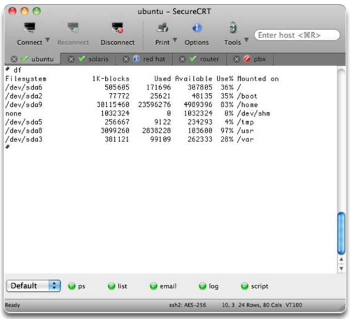
15 There are a number of excellent terminal emulation programs available for connecting to a networking device either by a serial connection over a console port or by a Telnet/SSH connection. Some of these include: PuTTY (Figure 1) Tera Term (Figure 2) SecureCRT (Figure 3) HyperTerminal OS X Terminal 15

16 Tera Term Secure CRT 16
 mode Privileged executive (Privileged EXEC) mode Global")
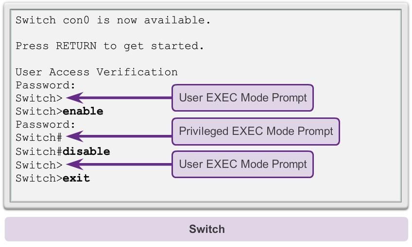
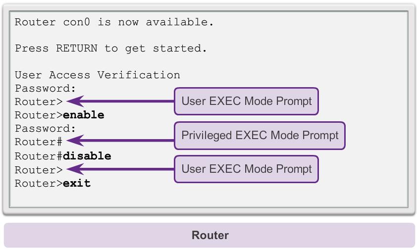
17 Cisco IOS Modes of Operation The CLI uses a hierarchical structure for the modes. In hierarchical order from most basic to most specialized, the major modes are: User executive (User EXEC) mode Privileged executive (Privileged EXEC) mode Global configuration mode Other specific configuration modes, such as interface configuration mode 17

18 Navigating the IOS The user EXEC mode is identified by the CLI prompt that ends with the > symbol. The privileged EXEC mode can be identified by the prompt ending with the # symbol. 18

19 Priviledged EXEC Mode 19

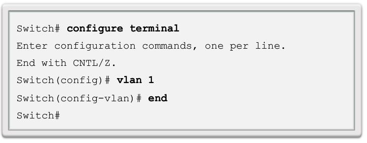
20 Navigating the IOS Global configuration mode and interface configuration modes can only be reached from the privileged EXEC mode. Specific Configuration Modes From the global configuration mode, the user can enter different sub-configuration modes. Each of these modes allows the configuration of a particular part or function of the IOS device. The list below shows a few of them: Interface mode - to configure one of the network interfaces (Fa0/0, S0/0/0) Line mode - to configure one of the physical or virtual lines (console, AUX, VTY) 20
21 Navigating between IOS Mode 21

22 Navigating the IOS Moving from and to Global Configuration Mode and Submodes To quit from the global configuration mode and return to the privileged EXEC mode, enter the exit command. 22

23 Navigating the IOS 23

24 Getting Basic - Hostnames When configuring a networking device, one of the first steps is configuring a unique device name, or hostname. Some guidelines for naming conventions are that names should: Start with a letter Contain no spaces End with a letter or digit Use only letters, digits, and dashes Be less than 64 characters in length Switch# configure terminal Switch(config)# hostname Sw-Floor-1 Sw-Floor-1(config)# 24

25 Limiting Access to Device Configurations The passwords introduced here are: Enable password - Limits access to the privileged EXEC mode Enable secret - Encrypted, limits access to the privileged EXEC mode Console password - Limits device access using the console connection VTY password - Limits device access over Telnet 25
26 Address Schemes - Ports and Addresses Each end device on a network must be configured with IP addresses. Some examples of end devices are: Computers (work stations, laptops, file servers, web servers) Network printers VoIP phones Security cameras Smart phones Mobile handheld devices (such as wireless barcode scanners) 26
27 IP Address v4 Figure 5.9 Classful IP addressing scheme. 27
28 IP Addresses Table 5.9 IPv4 classful addressing scheme First bits of address Number of bits of network address Number of bits of host address Number of network address ranges available Number of hosts per network address Class A million Class B Class C Class D Non-aggregatable 268 million 0 (Multicast) Multicast address Class E 1111 Experimental use 268 million 0 28
29 Addressing Scheme To access the switch remotely, an IP address and a subnet mask must be configured on the SVI: IP address - Together with subnet mask, uniquely identifies end device on the internetwork Subnet mask - Determines which part of a larger network is used by an IP address 29

30 Manual IP Address Configuration for End Devices 30

31 Automatic IP Address Configuration for End Devices 31

32 IP Address Conflicts Usually static IP addresses are used with servers and printers in a small- to medium-sized business network, while employee devices use DHCP-allocated IP address information. 32

33 Verifying Connectivity Testing the Loopback The ping command is used to verify the internal IP configuration on a local host. This test is accomplished by using the ping command on a reserved address called the loopback ( ). The loopback address, , is defined by the TCP/IP protocol as a reserved address that routes packets back to the host. 33
CHAPTER 2 ACTIVITY
 CHAPTER 2 ACTIVITY 2.1.1.1 1. CLI stands for 2. GUI stands for 3. Write the step you used to go to CLI interface on Windows 4. The OS, normally loads from a disk drive, into RAM. 5. The portion of the
Chapter 2. Chapter 2 A. Configuring a Network Operating System
 Chapter 2 Chapter 2 A Configuring a Network Operating System Chapter 2 Cisco IOS IOS stands for Internetwork Operating System It is a family of software used on most Cisco Systems routers and current Cisco
CCNA 1 Chapter 2 v5.0 Exam Answers %
 CCNA 1 Chapter 2 v5.0 Exam Answers 2015 100% 1. Which two features are characteristics of flash memory? (Choose two.) Flash provides nonvolatile storage. Flash receives a copy of the IOS from RAM when
Chapter 2: Configure a Network Operating System. Every computer requires an operating system to function, including computerbased
 2.0.1.1 Chapter 2: Configure a Network Operating System Every computer requires an operating system to function, including computerbased network devices such as switches, routers, access points, and firewalls.
MiPDF.COM. 3. Which procedure is used to access a Cisco 2960 switch when performing an initial configuration in a secure environment?
 CCNA1 v6.0 Chapter 2 Exam Answers 2017 (100%) MiPDF.COM 1. What is the function of the kernel of an operating software? It provides a user interface that allows users to request a specific task. The kernel
Lab Using the CLI to Gather Network Device Information Topology
 Topology Addressing Table Objectives Device Interface IP Address Subnet Mask Default Gateway R1 G0/1 192.168.1.1 255.255.255.0 N/A Lo0 209.165.200.225 255.255.255.224 N/A S1 VLAN 1 192.168.1.11 255.255.255.0
CCNA 1 Chapter 2 v5.0 Exam Answers 2013
 CCNA 1 Chapter 2 v5.0 Exam Answers 2013 1. Refer to the exhibit. A switch was configured as shown. A ping to the default gateway was issued, but the ping was not successful. Other switches in the same
CCNA Explorer 1 Chapter 11 Configuring & Testing Your Network
 CCNA Explorer 1 Chapter 11 Configuring & Testing Your Network 11.1.1 What is the system software in Cisco devices? The Cisco IOS provides devices with what network services? How is the IOS generally accessed?
CCNA 1 Final Exam Answers UPDATE 2012 eg.2
 CCNA 1 Final Exam Answers UPDATE 2012 eg.2 January 12th, 2012AdminLeave a commentgo to comments 1. When must a router serial interface be configured with the clock rate command? when the interface is functioning
1. Which OSI layers offers reliable, connection-oriented data communication services?
 CCNA 1 Practice Final Exam Answers v4.0 100% 1. Which OSI layers offers reliable, connection-oriented data communication services? application presentation session transport network 2. Refer to the exhibit.
CCNA 1 Final Exam Answers UPDATE 2012 eg.1
 CCNA 1 Final Exam Answers UPDATE 2012 eg.1 January 12th, 2012AdminLeave a commentgo to comments Which of the following are the address ranges of the private IP addresses? (Choose three.) 10.0.0.0 to 10.255.255.255
Chapter 6: Network Layer
 Chapter 6: Network Layer CCNA Routing and Switching Introduction to Networks v6.0 Chapter 6 - Sections & Objectives 6.1 Network Layer Protocols Explain how network layer protocols and services support
Chapter 11. Configuring and Testing Your Network
 Chapter 11 Configuring and Testing Your Network CCNA1-1 Chapter 11 Note for Instructors These presentations are the result of a collaboration among the instructors at St. Clair College in Windsor, Ontario.
Lab 7 Configuring Basic Router Settings with IOS CLI
 Lab 7 Configuring Basic Router Settings with IOS CLI Objectives Part 1: Set Up the Topology and Initialize Devices Cable equipment to match the network topology. Initialize and restart the router and switch.
Lab - Examining Telnet and SSH in Wireshark
 Topology Addressing Table Objectives Device Interface IP Address Subnet Mask Default Gateway R1 G0/1 192.168.1.1 255.255.255.0 N/A PC-A NIC 192.168.1.3 255.255.255.0 192.168.1.1 Part 1: Configure the Devices
Lab - Configuring a Switch Management Address
 Topology Addressing Table Objectives Device Interface IP Address Subnet Mask Default Gateway S1 VLAN 1 192.168.1.2 255.255.255.0 N/A PC-A NIC 192.168.1.10 255.255.255.0 N/A Part 1: Configure a Basic Network
Upon completion of this chapter, you will be able to answer the following questions:
 CHAPTER 1 Routing Concepts Objectives Upon completion of this chapter, you will be able to answer the following questions: What are the primary functions and features of a router? How do you connect devices
2. Which two functions of the OSI model occur at layer two? (Choose two.) physical addressing encoding routing cabling media access control
 physical addressing encoding routing cabling media access control") 1. Which of the following are the address ranges of the private IP addresses? (Choose three.) 10.0.0.0 to 10.255.255.255 200.100.50.0 to 200.100.25.255 150.150.0.0 to 150.150.255.255 172.16.0.0 to 172.31.255.255
1. Which of the following are the address ranges of the private IP addresses? (Choose three.) 10.0.0.0 to 10.255.255.255 200.100.50.0 to 200.100.25.255 150.150.0.0 to 150.150.255.255 172.16.0.0 to 172.31.255.255
Routing Concepts. 1.0 Routing Concepts. Chapter Introduction Class Activity - Do We Really Need a Map?
 Chapter 1 Routing Concepts 1.0 Routing Concepts 1.0.1.1 Introduction Networks allow people to communicate, collaborate, and interact in many ways. Networks are used to access web pages, talk using IP telephones,
Before you start the lab exercises see the lab administrator or EEE3080F tutor to get assigned to your routers.
 EEE00F Lab Basics of the Network Lab Student Lab Manual Before you start the lab exercises see the lab administrator or EEE00F tutor to get assigned to your routers. Contents. Resources used in the labs...
Chapter 5 Router and IOS Basics
 Chapter 5 Router and IOS Basics Benefits of Routing Routers provide Packet filtering Connections between local networks Traffic control Wide area network (WAN) connections Routers operate at the Network
Lab Configure Basic AP Security through IOS CLI
 Lab 8.3.1.2 Configure Basic AP Security through IOS CLI Estimated Time: 30 minutes Number of Team Members: Students will work in teams of two. Objective In this lab, the student will learn the following
Lab Configuring and Verifying Extended ACLs Topology
 Topology 2015 Cisco and/or its affiliates. All rights reserved. This document is Cisco Public. Page 1 of 8 Addressing Table Objectives Device Interface IP Address Subnet Mask Default Gateway R1 G0/1 192.168.10.1
This document is exclusive property of Cisco Systems, Inc. Permission is granted to print and copy this document for non-commercial distribution and
 This document is exclusive property of Cisco Systems, Inc. Permission is granted to print and copy this document for non-commercial distribution and exclusive use by instructors in the CCNA Exploration:
Chapter 4. Network Security. Part II
 Chapter 4 Network Security Part II CCNA4-1 Chapter 4-2 Introducing Network Security Securing Cisco Routers CCNA4-2 Chapter 4-2 Router Security Issues The Role of Routers in Network Security: Router security
Chapter 4: Routing Concepts. Routing & Switching
 Chapter 4: Routing Concepts Routing & Switching Routers are Computers Routers are specialized computers containing the following required components to operate: Central processing unit (CPU) Operating
Lab Student Lab Orientation
 Lab 1.1.1 Student Lab Orientation Objective In this lab, the students will complete the following tasks: Review the lab bundle equipment Understand the security pod topology Understand the pod naming and
Chapter 10 - Configure ASA Basic Settings and Firewall using ASDM
 Chapter 10 - Configure ASA Basic Settings and Firewall using ASDM This lab has been updated for use on NETLAB+ Topology Note: ISR G1 devices use FastEthernet interfaces instead of GigabitEthernet interfaces.
Overview of the Cisco NCS Command-Line Interface
 CHAPTER 1 Overview of the Cisco NCS -Line Interface This chapter provides an overview of how to access the Cisco Prime Network Control System (NCS) command-line interface (CLI), the different command modes,
Lab b Standard ACLs Instructor Version 2500
 Lab 11.2.1b Standard ACLs Instructor Version 2500 Objective Scenario Plan, configure, and apply a standard ACL to permit or deny specific traffic and test the ACL to determine if the desired results were
Introduction p. 1 Self-Assessment p. 9 Networking Fundamentals p. 17 Introduction p. 18 Components and Terms p. 18 Topologies p. 18 LAN Technologies
 Introduction p. 1 Self-Assessment p. 9 Networking Fundamentals p. 17 Introduction p. 18 Components and Terms p. 18 Topologies p. 18 LAN Technologies p. 19 Ethernet p. 19 WAN Technologies p. 21 Dedicated
Lab Configuring and Verifying Standard IPv4 ACLs (Instructor Version Optional Lab)
") (Instructor Version Optional Lab) Instructor Note: Red font color or gray highlights indicate text that appears in the instructor copy only. Optional activities are designed to enhance understanding and/or
(Instructor Version Optional Lab) Instructor Note: Red font color or gray highlights indicate text that appears in the instructor copy only. Optional activities are designed to enhance understanding and/or
Skills Assessment Student Practice
 Skills Assessment Student Practice Topology Assessment Objectives Part 1: Develop the IPv4 Address Scheme (15 points, 20 minutes) Part 2: Initialize and Reload Devices (10 points, 5 minutes) Part 3: Configure
CCNA 1 v5.0 R&S ITN Final Exam 2014
 CCNA 1 v5.0 R&S ITN Final Exam 2014 1 Refer to the exhibit. The network administrator enters these commands into the R1 router: R1# copy running-config tftp Address or name of remote host [ ]? When the
Lab Configuring Dynamic and Static NAT (Instructor Version Optional Lab)
") (Instructor Version Optional Lab) Instructor Note: Red font color or gray highlights indicate text that appears in the instructor copy only. Optional activities are designed to enhance understanding and/or
(Instructor Version Optional Lab) Instructor Note: Red font color or gray highlights indicate text that appears in the instructor copy only. Optional activities are designed to enhance understanding and/or
CCNA 1 Chapter 11 V4.0 Answers
 CCNA 1 Chapter 11 V4.0 Answers 1. Refer to the exhibit. What command will place the router into the correct mode to configure an appropriate interface to connect to a LAN? UBAMA# configure terminal UBAMA(config)#
Using Cisco IOS XE Software
 This chapter describes the basics of using the Cisco IOS XE software and includes the following section: Accessing the CLI Using a Router Console, on page 1 Accessing the CLI Using a Router Console Before
Lab Securing Network Devices
 Topology Addressing Table Objectives Device Interface IP Address Subnet Mask Default Gateway R1 G0/1 192.168.1.1 255.255.255.0 N/A S1 VLAN 1 192.168.1.11 255.255.255.0 192.168.1.1 PC-A NIC 192.168.1.3
Lab Configuring Dynamic and Static NAT (Solution)
") (Solution) Topology Addressing Table Objectives Device Interface IP Address Subnet Mask Default Gateway Gateway G0/1 192.168.1.1 255.255.255.0 N/A S0/0/1 209.165.201.18 255.255.255.252 N/A ISP S0/0/0 (DCE)
(Solution) Topology Addressing Table Objectives Device Interface IP Address Subnet Mask Default Gateway Gateway G0/1 192.168.1.1 255.255.255.0 N/A S0/0/1 209.165.201.18 255.255.255.252 N/A ISP S0/0/0 (DCE)
Configuring a Basic Wireless LAN Connection
 This module describes how to configure a wireless LAN (WLAN) connection between a wireless device, such as a laptop computer or mobile phone, and a Cisco 800, 1800 (fixed and modular), 2800, or 3800 series
Skills Assessment Student Training
 Skills Assessment Student Training Topology Assessment Objectives Part 1: Initialize Devices (6 points, 5 minutes) Part 2: Configure Device Basic Settings (33 points, 20 minutes) Part 3: Configure Switch
Lab Configuring and Verifying Standard IPv4 ACLs Topology
 Topology 2016 Cisco and/or its affiliates. All rights reserved. This document is Cisco Public. Page 1 of 10 Addressing Table Objectives Device Interface IP Address Subnet Mask Default Gateway R1 G0/1 192.168.10.1
Controlling Switch Access with Passwords and Privilege Levels
 Controlling Switch Access with Passwords and Privilege Levels Finding Feature Information, page 1 Restrictions for Controlling Switch Access with Passwords and Privileges, page 1 Information About Passwords
Lab Command Line Fundamentals Instructor Version 2500
 Lab 2.2.9 Command Line Fundamentals Instructor Version 2500 Objective Log into a router and go to the user and privileged modes. Use several basic router commands to determine how the router is configured.
Lab 1.4.6B Implementing Port Security
 Lab 1.4.6B Implementing Port Security Device Designation Device Name VLAN 1 Address Subnet mask S1 FC-ASW-1 10.0.0.2 255.255.255.0 PC1 Host 1 10.0.0.254 255.255.255.0 PC2 Host 2 10.0.0.253 255.255.255.0
CCNA2 Chapter 1 Practice
 CCNA2 Chapter 1 Practice Where should a crossover UTP cable be used? (Choose 2) To connect two PCs together directly. To connect a router to an Ethernet switch. To connect a PC to an Ethernet switch. To
ICND1. Switch Configuration Lab. All configurations have been set to factory defaults for these labs
 ICND1 Switch Configuration Lab TOPOLOGY 3xPC (hosts) 2x2950 (Layer 2 Switches) 1x3560 (Layer 3 Switch) 5x2811 (Routers, unused in this set of labs) All configurations have been set to factory defaults
Lab Establishing and Verifying a Telnet Connection Instructor Version 2500
 Lab 4.2.2 Establishing and Verifying a Telnet Connection Instructor Version 2500 Objective Establish a Telnet connection to a remote router. Verify that the application layer between source and destination
Lab Troubleshooting RIP
 Lab 7.2.6 Troubleshooting RIP Objective Set up an IP addressing scheme using class B networks. Configure RIP on routers. Observe routing activity using the debug ip rip command. Examine routes using the
Lab Troubleshooting Basic PPP with Authentication Topology
 Topology 2013 Cisco and/or its affiliates. All rights reserved. This document is Cisco Public. Page 1 of 8 Addressing Table Objectives Device Interface IP Address Subnet Mask Default Gateway R1 G0/1 192.168.1.1
MiPDF.COM. 1. Convert the decimal number 231 into its binary equivalent. Select the correct answer from the list below.
 CCNA1 v6.0 Pretest Exam Answers 2017 (100%) MiPDF.COM 1. Convert the decimal number 231 into its binary equivalent. Select the correct answer from the list below. 11110010 11011011 11110110 11100111* 11100101
Chapter 10 Configure Clientless Remote Access SSL VPNs Using ASDM
 Chapter 10 Configure Clientless Remote Access SSL VPNs Using ASDM Topology Note: ISR G1 devices use FastEthernet interfaces instead of GigabitEthernet Interfaces. 2016 Cisco and/or its affiliates. All
Chapter 2. Switch Concepts and Configuration. Part I
 Chapter 2 Switch Concepts and Configuration Part I CCNA3-1 Chapter 2-1 Note for Instructors These presentations are the result of a collaboration among the instructors at St. Clair College in Windsor,
SYSTEMS ADMINISTRATION USING CISCO (315)
") Page 1 of 11 Contestant Number: Time: Rank: SYSTEMS ADMINISTRATION USING CISCO (315) REGIONAL 2016 Multiple Choice: Multiple Choice (50 @ 10 points each) TOTAL POINTS (500 points) (500 points) Failure
Page 1 of 11 Contestant Number: Time: Rank: SYSTEMS ADMINISTRATION USING CISCO (315) REGIONAL 2016 Multiple Choice: Multiple Choice (50 @ 10 points each) TOTAL POINTS (500 points) (500 points) Failure
Lab 3: Basic Device Configuration
 Lab 3: Basic Device Configuration University of Jordan Faculty of Engineering & Technology Computer Engineering Department Computer Networks Laboratory 907528 2 Lab 3: Basic Device Configuration **Given
Lab Configuring Basic RIPv2 (Solution)
") (Solution) Topology 2017 Cisco and/or its affiliates. All rights reserved. This document is Cisco Public. Page 1 of 15 Addressing Table Objectives Device Interface IP Address Subnet Mask Default Gateway
(Solution) Topology 2017 Cisco and/or its affiliates. All rights reserved. This document is Cisco Public. Page 1 of 15 Addressing Table Objectives Device Interface IP Address Subnet Mask Default Gateway
Lab 1. CLI Navigation. Scenario. Initial Configuration for R1
 Lab 1 CLI Navigation This lab covers the most basic skills for accessing and using the command-line interface (CLI) on a Cisco router or switch. Many of the small, picky details of how the CLI works cannot
Controlling Switch Access with Passwords and Privilege Levels
 Controlling Switch Access with Passwords and Privilege Levels Finding Feature Information, page 1 Restrictions for Controlling Switch Access with Passwords and Privileges, page 1 Information About Passwords
Configuring Security with Passwords, Privileges, and Logins
 Configuring Security with Passwords, Privileges, and Logins Cisco IOS based networking devices provide several features that can be used to implement basic security for CLI sessions using only the operating
Chapter 11: Networks
 Chapter 11: Networks Devices in a Small Network Small Network A small network can comprise a few users, one router, one switch. A Typical Small Network Topology looks like this: Device Selection Factors
Lab Configuring Basic Switch Settings (Solution)
") (Solution) Topology Addressing Table Objectives Device Interface IP Address Subnet Mask Default Gateway S1 VLAN 99 192.168.1.2 255.255.255.0 192.168.1.1 PC-A NIC 192.168.1.10 255.255.255.0 192.168.1.1
(Solution) Topology Addressing Table Objectives Device Interface IP Address Subnet Mask Default Gateway S1 VLAN 99 192.168.1.2 255.255.255.0 192.168.1.1 PC-A NIC 192.168.1.10 255.255.255.0 192.168.1.1
Lab Configuring an ISR with SDM Express
 Lab 5.2.3 Configuring an ISR with SDM Express Objectives Configure basic router global settings router name, users, and login passwords using Cisco SDM Express. Configure LAN and Internet connections on
Networking Basics. Crystal Printer Network Installation Guidelines
 Networking Basics & Crystal Printer Network Installation Guidelines 1. Overview This guide is intended to provide the necessary basic knowledge of wireless networking needed to enable the Crystal printer
Chapter 10 Configure AnyConnect Remote Access SSL VPN Using ASDM
 Chapter 10 Configure AnyConnect Remote Access SSL VPN Using ASDM Topology Note: ISR G1 devices use FastEthernet interfaces instead of GigabitEthernet interfaces. 2015 Cisco and/or its affiliates. All rights
Using the Command-Line Interface
 CHAPTER 1 The Catalyst 2950 switches are supported by Cisco IOS software. This chapter describes how to use the switch command-line interface (CLI) to configure the software features. For a complete description
Chapter 10 Configure Clientless Remote Access SSL VPNs Using ASDM
 Chapter 10 Configure Clientless Remote Access SSL VPNs Using ASDM This lab has been updated for use on NETLAB+ Topology Note: ISR G1 devices use FastEthernet interfaces instead of GigabitEthernet Interfaces.
Lab Troubleshooting Using traceroute Instructor Version 2500
 Lab 9.3.4 Troubleshooting Using traceroute Instructor Version 2500 294-833 CCNA 2: Routers and Routing Basics v 3.1 - Lab 9.3.4 Copyright 2003, Cisco Systems, Inc. Objective Use the traceroute Cisco IOS
Getting Started with the VG248
 CHAPTER 2 Before you can configure the telephony features on the VG248 to interact with the analog phones, you must first configure the basic network, SNMP, and password settings. These settings enable
CCNA 1 Chapter 6 v5.0 Exam Answers 2013
 CCNA 1 Chapter 6 v5.0 Exam Answers 2013 1 After troubleshooting a router, the network administrator wants to save the router configuration so that it will be used automatically the next time that the router
Configuring TACACS+ Finding Feature Information. Prerequisites for TACACS+
 Finding Feature Information, page 1 Prerequisites for TACACS+, page 1 Information About TACACS+, page 3 How to Configure TACACS+, page 7 Monitoring TACACS+, page 16 Finding Feature Information Your software
CCENT Practice Certification Exam # 2 - CCNA Exploration: Accessing the WAN (Version 4.0)
") CCENT Practice Certification Exam # 2 - CCNA Exploration: Accessing the WAN (Version 4.0) 1. Data is being sent from a source PC to a destination server. Which three statements correctly describe the function
CCENT Practice Certification Exam # 2 - CCNA Exploration: Accessing the WAN (Version 4.0) 1. Data is being sent from a source PC to a destination server. Which three statements correctly describe the function
Lab Designing and Implementing a VLSM Addressing Scheme. Topology. Objectives. Background / Scenario
 CSNB214 Packet Tracer Lab Designing and Implementing a VLSM Addressing Scheme Topology Objectives Part 1: Examine Network Requirements Part 2: Design the VLSM Address Scheme Part 3: Cable and Configure
PT Activity: Configure AAA Authentication on Cisco Routers
 PT Activity: Configure AAA Authentication on Cisco Routers Instructor Version Topology Diagram Addressing Table Device Interface IP Address Subnet Mask R1 Fa0/0 192.168.1.1 255.255.255.0 S0/0/0 10.1.1.2
Accessing the WAN Chapter 4 - PART II Modified by Tony Chen 07/20/2008
 Network Security Accessing the WAN Chapter 4 - PART II Modified by Tony Chen 07/20/2008 ITE I Chapter 6 2006 Cisco Systems, Inc. All rights reserved. Cisco Public 1 Notes: If you see any mistake on my
Lab Configuring Port Address Translation (PAT) (Instructor Version)
 (Instructor Version)") (Instructor Version) Instructor Note: Red font color or gray highlights indicate text that appears in the instructor copy only. Topology Addressing Table Objectives Device Interface IP Address Subnet Mask
(Instructor Version) Instructor Note: Red font color or gray highlights indicate text that appears in the instructor copy only. Topology Addressing Table Objectives Device Interface IP Address Subnet Mask
Lab : Challenge OSPF Configuration Lab. Topology Diagram. Addressing Table. Default Gateway. Device Interface IP Address Subnet Mask
 Topology Diagram Addressing Table Device Interface IP Address Subnet Mask Default Gateway Fa0/0 HQ S0/0/0 S0/0/1 Lo1 10.10.10.1 255.255.255.252 Fa0/0 Branch1 S0/0/0 S0/0/1 Fa0/0 Branch2 S0/0/0 S0/0/1 PC1
Antonio Cianfrani. Packet Tracer
 Antonio Cianfrani Packet Tracer Packet Tracer (1/2) Packet Tracer? Cisco Packet Tracer is a software able to emulate CISCO networking devices. Packet Tracer features: Allows to create network topologies
Using Cisco IOS Software
 APPENDIX A This appendix describes the basics about using the Cisco IOS software that is installed on every Cisco ubr905 and Cisco ubr925 cable access routers: Accessing the Command-Line Interface, page
Interconnecting Cisco Networking Devices Part 1 ICND1
 Interconnecting Cisco Networking Devices Part 1 ICND1 Course Length: 5 days Course Delivery: Traditional Classroom Online Live Course Overview Interconnecting Cisco Networking Devices, Part 1 (ICND1) v3.0
CCNA Semester 2 labs. Labs for chapters 2 10
 CCNA Semester 2 labs Labs for chapters 2 10 2.2.2.5 Lab - Configuring IPv4 Static and Default Routes 2.3.2.4 Lab - Troubleshooting Static Routes 3.2.1.9 Lab - Configuring Basic RIPv2 5.2.2.9 Lab - Configuring
Lab Configuring Switch Security Features Topology
 Topology Addressing Table Objectives Device Interface IP Address Subnet Mask Default Gateway R1 G0/1 172.16.99.1 255.255.255.0 N/A S1 VLAN 99 172.16.99.11 255.255.255.0 172.16.99.1 PC-A NIC 172.16.99.3
Administration of Cisco WLC
 Using the Controller Interface, on page 1 Enabling Web and Secure Web Modes, on page 6 Telnet and Secure Shell Sessions, on page 8 Management over Wireless, on page 13 Configuring Management using Dynamic
Configuring Secure Shell (SSH)
") Prerequisites for Configuring Secure Shell, page 1 Restrictions for Configuring Secure Shell, page 2 Information About Configuring Secure Shell, page 2 How to Configure Secure Shell, page 4 Monitoring
Prerequisites for Configuring Secure Shell, page 1 Restrictions for Configuring Secure Shell, page 2 Information About Configuring Secure Shell, page 2 How to Configure Secure Shell, page 4 Monitoring
Lecture (02) Switch remote configuration peer2peer star network clients/server star network Traffic analysis using Packet Tracer
 Switch remote configuration peer2peer star network clients/server star network Traffic analysis using Packet Tracer") Lecture (02) Switch remote configuration peer2peer star network clients/server star network Traffic analysis using Packet Tracer Dr. Ahmed M. ElShafee ١ Topology ٢ Preparation ٣ Commands summery ٤ enabl
Lecture (02) Switch remote configuration peer2peer star network clients/server star network Traffic analysis using Packet Tracer Dr. Ahmed M. ElShafee ١ Topology ٢ Preparation ٣ Commands summery ٤ enabl
Skills Assessment Student Training Exam
 Skills Assessment Student Training Exam Time: 20 minutes Given an IP address and mask of (address / mask), design an IP addressing scheme that satisfies the following requirements. Network address/mask
Interconnecting Cisco Networking Devices Part 1 ( )
") Interconnecting Cisco Networking Devices Part 1 (100-101) Exam Description: The 100-101 Interconnecting Cisco Networking Devices Part 1 (ICND1) is a 1.5- hour exam with 50 60 questions. The 100-101 Interconnecting
Interconnecting Cisco Networking Devices Part 1 (100-101) Exam Description: The 100-101 Interconnecting Cisco Networking Devices Part 1 (ICND1) is a 1.5- hour exam with 50 60 questions. The 100-101 Interconnecting
Using the Cisco NCS Command-Line Interface
 CHAPTER 2 This chapter provides helpful tips for understanding and configuring the Cisco Prime Network Control System (NCS) from the command-line interface (CLI). The Cisco NCS can be deployed for small,
CCRI Networking Technology I CSCO-1850 Spring 2014
 CCRI Networking Technology I CSCO-1850 Spring 2014 Instructor John Mowry Telephone 401-825-2138 E-mail jmowry@ccri.edu Office Hours Room 2126 Class Sections 102 Monday & Wednesday 6:00PM-9:50PM, starts
Lab Configure Basic AP security through GUI
 Lab 8.3.1.1 Configure Basic AP security through GUI Estimated Time: 30 minutes Number of Team Members: Students will work in teams of two. Objective In this lab, the student will learn the following objectives:
ICND1 v2.0 Interconnecting Cisco Networking Devices Part 1 CCENT & Part of CCNA Rout/Switch
 ICND1 v2.0 Interconnecting Cisco Networking Devices Part 1 CCENT & Part of CCNA Rout/Switch Course Length: 5 days Course Delivery: Traditional Classroom Online Live Course Overview Interconnecting Cisco
Exam E1 Copyright 2010 Thaar AL_Taiey
 Exam E1 2 Exam E1 E1-1. Which of the following statements is true regarding the internetwork shown in Figure E1-1? (Select all that apply) Figure E1-1 A Sample Internetwork A. The link number 15 uses a
SEMESTER 2 Chapter 1 Planning and Cabling a Network V 4.0
 SEMESTER 2 Chapter 1 Planning and Cabling a Network V 4.0 135 points 1.1.1 What are the common components between a router and other computers? CPU RAM ROM Operating System 1.1.1.2 What does a router connect?
Lab Managing Router Configuration Files with Terminal Emulation Software
 Lab Managing Router Configuration Files with Terminal Emulation Software Topology Addressing Table Objectives Device Interface IP Address Subnet Mask Default Gateway R1 G0/1 192.168.1.1 255.255.255.0 N/A
Using the Command-Line Interface
 CHAPTER 1 The Cisco Metro Ethernet (ME) 3400E Series Ethernet Access switch is supported by Cisco IOS software. This chapter describes how to use the switch command-line interface (CLI) to configure software
Lab 9.6.2: Challenge EIGRP Configuration Lab
 Topology Diagram Addressing Table Device Interface IP Address Subnet Mask Default Gateway HQ BRANCH1 BRANCH2 PC1 PC2 PC3 Fa0/0 S0/0/0 S0/0/1 Lo1 Fa0/0 S0/0/0 S0/0/1 Fa0/0 S0/0/0 S0/0/1 NIC NIC NIC All
Using the Command-Line Interface
 CHAPTER 2 This chapter describes the Cisco IOS command-line interface (CLI) and how to use it to configure your Cisco ME 3400 Ethernet Access switch. It contains these sections: Understanding Command Modes,
Using the Command-Line Interface
 Information About, page 1 How to Use the CLI to Configure Features, page 5 Information About Command Modes The Cisco IOS user interface is divided into many different modes. The commands available to you
CCNA Semester 1 labs. Part 1 of 2 Labs for chapters 1 7
 CCNA Semester 1 labs Part 1 of 2 Labs for chapters 1 7 2.3.3.3 Lab - Building a Simple Network 2.3.3.4 Lab - Configuring a Switch Management Address 3.4.1.2 Lab - Using Wireshark to View Network Traffic
Light Mesh AP. User s Guide. 2009/2/20 v1.0 draft
 Light Mesh AP User s Guide 2009/2/20 v1.0 draft i FCC Certifications This equipment has been tested and found to comply with the limits for a Class B digital device, pursuant to Part 15 of the FCC Rules.
Router Startup and Configuration
 Router Startup and Configuration Router Startup In general, the boot process follows these steps: Test hardware (POST) Load the bootstrap program Locate and load the Cisco IOS Locate and load the router