HART/ Modbus TCP Gateway GT200-HT-MT User Manual V 1.2 REV A SST Automation
|
|
|
- Constance Sutton
- 5 years ago
- Views:
Transcription
1 HART/ Modbus TCP Gateway GT200-HT-MT User Manual V 1.2 REV A SST Automation SUPPORT@SSTCOMM.COM
2 Catalog 1 Product Overview Product Function Product Features Technical Specifications Safety and Explosion-Proof Features Related Products Revision History Quick Start Guide Configuration of Gateway Pre-configured Settings Software Configuration Function Demo Hardware Descriptions Product Appearance Indicators Configuration Switch/Button Status Setting Switch Internal / External Sampling Resistor Switch Interface Power Interface Ethernet Interface HART Interface Topology of GT200-HT-MT and Fieldbus Devices Software Instructions Software Interface Description Software Functional Specifications Configure the Fieldbus Configure the HART Fieldbus Conflict Detection AutoMap Upload Configuration Download Configuration Memory Data Display Diagnose Switching Tools Working Principle Flowchart of Executing One HART Command Universal Send and Receive Data
3 5.3 Trigger Command Data Exchange with Modbus TCP Installation Machine Dimension Installation Method
4 1 Product Overview 1.1 Product Function GT200-HT-MT is a gateway that can exchange data between HART and Modbus TCP. HART interface can be configured as a primary master or a secondary master. Modbus TCP side acts as a slave. 1.2 Product Features Simple to use: users can refer to product manuals and application case to achieve communication in a short time according to the requirements of the configuration; Ethernet 10/100M adaptive; Rich debugging features, the command of the subsection mapping function, the visual display of data exchange, HART slave command diagnostic functions greatly facilitate the user's communication test; With configuration software, it can configure the HART command and parameters of Modbus TCP Server. 1.3 Technical Specifications [1] HART interface can be used as a primary master or the secondary master; [2] Supports one HART channel, supports connecting at most 13 instruments with gateway internal resistor (270 Ω/2W) and supports connecting 15 instruments with an external resistor (250Ω/2W); [3] HART interface supports single-point and multi-point mode; [4] Under single-point mode, supports data burst operation; [5] Supports all commands of the HART protocol; [6] Each HART command can be configured for change-of-state output, polling output, initialization output or no output; [7] Supports up to 100 HART commands, the output data buffer area can be up to 2000 bytes, and the input data 4
5 buffer area up to 3000 bytes; [8] Each channel can choose to use an internal or external HART sampling resistor; [9] Supports IP address conflict detection and auto routing,modbus TCP slave supports at most 36 connection and 512 command request simultaneously; [10] Power: 24VDC (9V~30V), <100mA (24VDC) [11] Working circumstance temperature: -4 ~140 (-20 ~60 ), Rel Humidity: 5%~ 95% (non-condensing); [12] External dimensions(w*h*d):1.57 in*4.92 in*4.33 in(40mm*125mm*110mm); [13] Installation: 1.38 in (35mm) DIN RAIL [14] Protection Level: IP Safety and Explosion-Proof Features GT200-HT-MT is not the product with the features of safety and explosion-proof, please put it in the control room when using. 1.5 Related Products The related products include: GT200-3HT-RS and GT200-HT-DP etc. If you want to get more information about related products, please visit SSTCOMM website: Revision History Revision Date Chapter Description REV A 02/11/2017 ALL V1.2_Rev A new release, open the memory data display, diagnosis, mode selection and other functions, increase the 4.2.7, chapters. 5
 with that of computer; 3.")
6 2 Quick Start Guide The following example introduces the use of the Gateway. 2.1 Configuration of Gateway Pre-configured Settings 1. Turn gateway's "mode" DIP switch to "ON" and "function" DIP switch to "OFF" 2. Use crossed network cable to connect the gateway's Ethernet port (RJ45 interface) with that of computer; 3. Power on the gateway, now the IP address of the gateway is fixed: and it is configurable Software Configuration 1. Open the SST-HE-CFG software installed on your computer; 2. Click "Fieldbus", in the "Mode" item on the right, choose Modbus TCP; 3. Click "Serial setting" in "config" menu, pop up the "Select the serial port" dialog box; 6

7 4. Click "OK"; Select the gateway and Sign in the popup "Search Equipment" dialog box; 5. Select the "Fieldbus" in the tree view on the left, configure as below in the right interface; 6. Click the channel in the tree view on the left, the table appearing on the right is configured as below: 7

 and it only allows digital communication.")

8 Note: In the HART protocol, it specifies that the device with slave address 0 works under single point mode, it allows digital communication and analog communication exist at the same time. The device with slave address 0~15 works under the multipoint mode, the analog output of the device is the minimum value (4mA) and it only allows digital communication. The protocol also specifies that the default factory address is No Right click the channel, select "Add Node" in the popup menu as below: 8. Right click: "Node(0)", select "Add Command" in the popup menu, add Command ID1 in the popup dialog box (double click "Command ID1" or select "Command ID1" and click "»"), click OK to return. 8


9 9. Click "Command ID1", the configuration table on the right is configured as below: 10. Click the icon, in the pop-up dialog box, select the Ethernet port with which gateway is connected to the computer, and then click Download: 9

10 2.2 Function Demo The HART interface of the gateway GT200-HT-MT connects with a 2-wire pressure transmitter with slave address 0. The Ethernet port is connected to the PC through network cable. The configured Modbus POLL software in PC can simulate to work as a Modbus TCP master, and then you can see the main variable value of the pressure transmitter in data exchange window: 10
11 3 Hardware Descriptions 3.1 Product Appearance 24VDC Interface Status indicators Ethernet interface Switch of sampling resistor HART Interface DIP Switch Note: This picture is for reference only. Product appearance should refer to the real object. 11
12 3.2 Indicators Indicator State State description TX Blinking HART channel data is sending OFF No data sending RX Blinking HART channel data is receiving OFF No data receiving NS Green LED OFF No Modbus TCP data is exchanging Green LED Blinking Modbus TCP data is exchanging Red LED ON Indicate confliction of IP address Connection OFF, configuration status, DHCP, BOOTP, IP Red LED Blinking MS address conflict detection with Modbus TCP Red LED Blinking (For 3 seconds) Connection OFF with Modbus TCP 3.3 Configuration Switch/Button Status Setting Switch Configuration switch is located at the bottom of product, bit 1 is the mode selecting bit and bit 2 is the function setting bit. Off On 1 2 Debugging (bit 1) Configuration (bit 2) Description Off Off Run mode, enable read/write the configuration data Off On Run mode, disable read/write the configuration data On Off Configuration mode, IP address is fixed: , User can read/write the configuration data On On Reserved Note: After re-configuring the switch, you have to restart the GT200-HT-MT to make the settings take effect! (Power off then Power On) 12
13 3.3.2 Internal / External Sampling Resistor Switch GT200-HT-MT can choose using the internal sampling resistor or external sampling resistor to get the HART signal. The specification of the internal resistor is 270Ω, 2W. When the power of the sampling resistor is more than 2W, you must use an external resistor. Switch to ON, using the internal sampling resistor Switch to OFF, using the external sampling resistor 3.4 Interface Power Interface GND NC 24V+ Pin Function 1 Power GND 2 NC(Not Connected) 3 24V+, DC Positive 24V 13

14 3.4.2 Ethernet Interface Ethernet interface uses RJ-45 plug-in; its pin (standard Ethernet signal) is defined as below: Pin S1 S2 S3 S4 S5 S6 S7 S8 Signal description TXD+, Tranceive Data+, Output TXD-, Tranceive Data-, Output RXD+, Receive Data+, Input Bi-directional Data+ Bi-directional Data- RXD-, Receive Data-, Input Bi-directional Data+ Bi-directional Data HART Interface Symbol HARTLOOP+ HARTLOOP- NC HART Channel Function Connect HART signal negative Connect 24V power negative Not connected 14
15 3.5 Topology of GT200-HT-MT and Fieldbus Devices 15
16 Note: 1. Some HART slave instrument need to perform self-test and other internal work when power is on, they may not start HART communication, then gateway cannot receive the response data of the instrument right now. It is recommended the HART slave instrument and gateway uses separate power supply so that the gateway can immediately establish communication with instrument. 2. When configuring HART commands in the software SST-HE-CFG, the commands need to be configured according to the actual demands. To improve the speed of bus communication, it is recommended not to configure the empty node (in fact, not connected to the node) and empty commands (the actual unnecessary commands). 16

17 4 Software Instructions 4.1 Software Interface Description SST-HE-CFG is configuring software based on Windows platform and it is used to configure HART series products of gateway. The following describes how to use the software SST-HE-CFG to configure the product GT200-HT-MT. Double-click on the icon to enter the main interface of software: Menu Bar Title Bar Tool Bar Equipment section: can choose the operating targets, including field bus or subnet, add the nodes and commands Configuration section: Input configuration parameters, gray part is not modifiable, white part is modifiable Notes section: The specific explanation of the nouns appearing in the configuration and devices to help users understand Tool Bar: Toolbar interface shown as follow: 17

18 The function from left to right is: New, Save, Open, AddChannel, DelChannel, AddNode, DelNode, AddCmd, DelCmd, Upload, Download, AutoMap, Conflict, Export, Memory, Diagnose, Debug and Mode Switch. GT200-HT-MT doesn't support function of "Memory", "Diagnose", "Debug" and "Mode switch" temporarily. New: Create a new configuration file Save: Save the configuration file Open: Open the configuration file AddChannel: This function can't be used temporarily DelChannel: This function can't be used temporarily AddNode: Add a HART slave node DelNode: Delete a HART slave node AddCmd: Add a HART command DelCmd: Delete a HART command 18
19 Upload: Read the configuration information from the module and shown in the software Download: Download the configuration file to the gateway AutoMap: Used to automatically calculate the mapped memory address without confliction by each command Conflict: To check whether there are some conflicts with configured commands in the gateway memory data buffer Export: Output current configuration to the local hard disk and saved as Excel spreadsheet form function temporarily. Memory: Show the data exchange situation inside of the gateway. GT200-HT-MT doesn't support this Diagnose: through this function could analyze operating condition of fieldbus device; also it can finish some certain analysis. GT200-HT-MT doesn't support this function temporarily. Debug: through this function could send any request frame to Hart fieldbus and show the response information received in HART, convenient to debug. GT200-HT-MT doesn't support this function temporarily. Mode Switch: Specify that the operation of the gateway is debugging or configuring. GT200-HT-MT 19

20 doesn't support this function temporarily. 4.2 Software Functional Specifications Configure the Fieldbus Click the "Fieldbus" in the tree view on the left, select "Modbus TCP" in the "Mode select" in the configuring plate on the right and then click enter to confirm. It is shown below: Here user can configure some parameters: IP setting mode: Static configuration, BOOTP, DHCP optional; IP address: Set the IP address of GT200-HT-MT; Subnet mask: Set the subnet mask of device; Gateway address: Set the gateway address of device; DNS1: Default 0; DNS2: Default 0; 4.2.2Configure the HART Fieldbus Set the Parameters of HART Channel Click the "HartChannel0" in the tree view, the configuration plate will be shown in the right place: 20

21 Master type: Primary master, Secondary master Network mode: Select the networks link as single or multiple points, under the single point the gateway can only communicate with the slave device whose address is 0; Maximum repetitions: Select times of command resending, range: 0~5 Enable Polling: Whether to use polling function, "Enable" means using polling function. Polling time: Set the polling time (Time interval between one command sending and beginning to send next command), the range is 256~65535ms Response timeout: Set the maximum time of waiting response from slave, the range is 256~65535ms Input data timeout clear/keep: After HART command exceeds the setting no-response times, whether to clear input data buffer area of HART Timeout times: Set the timeout times Add Slave Nodes Click the selected HART channel, right click the mouse and select "Add Node" in the popup menu. 21


22 Click the added node, set slave address in the right configuration plate, and please notice that HART channel can only be equipped with one slave node whose address is 0. Note: When configured node numbers are more than the actual connected devices, the redundant node will lead to the longer time of polling circle; so, it is recommended that configured node numbers should corresponds with actual devices Add Commands Click the selected "Node ()", right click the mouse and select "Add Command" in the popup menu 22


23 Choose the command you want to add in the popup dialog box, and then click "OK" to exit: Note: the same command can only be configured once in one node Configure Slave Commands Click the command ID in the tree view; you will see the configuration plate of command in the right place: 23
24 Mode of outputting command: You can use the execution way of the command, change-of-state, polling output, Initialization output and disable output optional; Change-of-state output: Execute this command once s data buffer of HART changes Polling output: This order is put in the polling list, executed periodically Initialization output: Execute the command only once when power is on Disable output: the command will not be sent. Memory starting address of sending data: Set the memory starting address of output data by this command, the range is 3000~4999; The register starting address of sending data: the property is automatically calculated by gateway, used for register addressing; Sending data length (byte): used to set the length of output data by this command; Sending data length (word): the property is automatically calculated by gateway, used for user checking output data length, 1 word=2 byte; Memory starting address of receiving data: set the memory address of input data by this command. Response data only includes data area of HART frame; The register starting address of receiving data: the property is automatically calculated by gateway, used for register addressing; Receiving data length (byte): set the length of input data by this command; Receiving data length (word): the property is automatically calculated by gateway, used for user checking output data length conveniently, 1 word=2 byte; Command index: the property is automatically calculated by the configuration software, it indicates the index in the configured command list this command belongs to Delete Commands Select the command need to be deleted, Right click the mouse and click "Delete Command". Through the menu command can also be the same action. 24

25 Delete Nodes Select the node needed to be deleted, Right click the mouse and click "Delete Node". Through the menu command can also be the same action Advanced Options to Configure Slave Commands When using HART command configuration, sometimes users want to get one part data of one command. For example, No.1 HART command. The float value of main variable is only needed, no need to get unit of main variable, this is why advanced option exists. Advanced options is actually the execution of "segment mapping function", it cut the response data of HART command and get the segment data. Users can get any part data they want. Below is the interface of Advanced Options: This interface details is described in chapter , so here we don't describe it. The below is the example of No.3 HART command, to show how to use "Segment Mapping" function, we can see one "configuration" button after the "receive data project configuration" option, click it: 25

26 There are many parts in "Bytes". For example, "Command Status" means the communication status and relevant code of HART response command, "Byte0-3" means byte 0 to 3 of data area of HART response command, and so on. In the above example, click "Byte5-8" will show the Primary Variable in the left bottom area. Other columns have the relevant explanation. First to explain the "Mapped Address": Bytes: response bytes of "Response Data"; Memory Address: assigned memory address which this byte is located in memory buffer area of GT200-HT-MT; Modbus register address: the relevant Modbus register address of "Memory Address"; Note: this address is not a single address, which is the same memory area which it occupied. Byte swap: there are two options, "no swap" and "register swap", swap option is only valid to float type data. When using "no swap", the byte order is byte1, byte2, byte3 and byte4. After using "register swap", the byte order will be byte3, byte4, byte1 and byte2. For example, the original data is 0x , it will be 0x after using "register swap". 26
27 Choose "Byte0-3" and "Byte5-8", click auto mapping, as shown below: Close the dialog box, download the configuration into GT200-HT-MT. Others are the same with "Basic Mode" Conflict Detection Conflict detection is used to check the distribution condition of the input and output data of all commands stored in the memory. Click icon will show the conflict detection interface as follow: 27

28 The left side is configuration commands, the right side is data memory address including receive data storage address and send data storage. Upper side is memory distribution of the HART's sending data; lower side is memory distribution of the HART's receiving data. When one memory unit is configured with two commands or more, the memory unit will display red color. When the distributed memory exceeds the defined scale of gateway, the exceeding part will display yellow color. White color area shows the usable memory. Green color area indicates occupied memory. Clicking one command, the distribution chart shown in blue will show the storage location of input/output data AutoMap Automap will automatically distribute the memory with no confliction according to the input/output bytes number by users' commands. You should set the correct input/output bytes for each commands, then click label, select "yes" in the 28


29 popup menu Upload Configuration Select the configuration interface: Show the "Ethernet Config" interface as below: When checking "Use the search function", it will search all identifiable hardware when the software is communicating with the hardware and will be shown in the device list: 29
30 Select the device, click "Sign in" to connect the device. When not checking "Use the search function", it will only search appointed hardware and only show this hardware in the device list. Click the upload icon again, pop up the dialog box below: Click "Upload data" button. 30
31 Now, user can upload the configuration of GT200-HT-MT into the software and shown in the software Download Configuration After configuring the command, click button, pop up the dialog box below: Click download data. Note: Before downloading, please confirm all configuration data are correct Memory Data Display Show the data exchange inside of the gateway, users can use this function to debug the HART fieldbus in the absence of the EtherNet/IP side. Steps are as follows: 1. Ensure that the GT200-HT-MT's function bit of DIP switch is in the ON state and the mode bit of DIP switch is in the OFF state, restart the gateway. GT200-HT-MT is in the run mode. 2. Use a network line to connect the GT200-HT-MT's RJ-45 port and computer. Open the software 31

32 "SST-HE-CFG", Click "Tool Select Mode" and choose debug mode and then click on the icon, you can also click to choose debug mode. Choose the correct gateway in the device scanning window, interface is as follows: As is shown in the table, upper table shows the memory distribution of HART input data, lower table shows the output data. When you need to change the output data, click the "stop" button firstly, then change the related data or load the already saved data table, at last, click the "sending data". 32
33 4.2.8 Diagnose The device diagnostics function allows the user to know which devices are not communicating properly, the execution of commands assigned, the status of the gateway's data transmission and reception, the display of specific commands, and the real-time display of HART device data. The steps are as follows: 1) First, dial the DIP switch of GT200-HT-MT to "1OFF2OFF", then power on again. At this moment GT200-HT-MT is in running mode. 2) Connect the network port of GT200-HT-MT to the computer, open the HTConfig software, click debug mode pop up the dialog box "Tools -> Select Mode", then select the diagnose in the tool or click the icon, select the debug mode, click OK, and then click software pop up a dialog box to upload the gateway configuration, as shown below: 33

 Click \"OK\" to")

34 3) Click "Upload Data" to pop up the following picture: 4) Click "OK" to enter the diagnostic interface: 34
35 Click "Channel 1" in this interface, the right side of the gateway will display the status of the HART bus section, click "Update" will refresh the data once, click "Reset" will clear the system status, click " periodically refresh", the software will update the data in 500ms. 5) Click Node (x) appears below: This screen shows the response status of the configured command. Click "Update" will refresh these command status, "Cycle Update" will update the command status 500ms 6) Double-click 0, 1, 2, 3, 6, 11, 12, 13, 14, 15, 16, 17, 18, 19 commands will pop up their command information, input 6, 17, 18, 19 commands. Double click "CMD0" to pop up the following window: 35


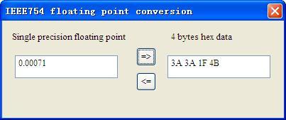
36 Click "Update" to update the data, "Edit" in the read-only command does not work Switching Tools In the "Tools" menu, there are two practical tools: They are used to switch between IEEE754 and PACKED ASCII conveniently. 36
37 37
38 5 Working Principle The gateway internally opens up a length of 8156 bytes of memory as input and output buffers which exchange data. 0 ~ 4999 memory is used as the storage area of the HART input data and output data. 5000~8155 memory is used as the storage area of the status of three HART channel and control variables. The specific assignment is shown in the table below: Three HART channel sharing memory HART channel Gateway memory address Corresponding Modbus register address Data shift offset in channel Read/write permission Description read The HART data input area read, write The HART data 9 output area read Device 0_cmd0 data Device 1_cmd0 data 9 Device 15_cmd0 data H 320 Gateway status L 321 Gateway HART port sending times H 322 Gateway HART port receive times L 323 HART communication error times Reserved H 324 The response status Device 0_cmd L 325 The response status of device 1_cmd0 The response 38
39 status of Device15 _cmd The response status of user command Reserved H 440 Universal receive label L 441 Universal receive error counter Universal receive data length Universal receive data Reserved HART data output area H 744 Read/Write Reset to send, receive, error counter L 745 Polling enabled H 746 Trigger label L 747 Trigger command Reserved H 748 Universal send label L 749 Universal mode enabled Universal send data length Universal send data The HART data input area: Store the data that HART slave device sends to gateway. All command response data of HART channel will be mapped here. The HART data output area: Store the data that the gateway sends to the HART slave device. All HART command will get the output data here. Device 0_cmd0~ Device 15_cmd0: When operating one slave command for the first time, the gateway 39
40 internally will automatically execute the No. 0 command to obtain the device information (to obtain the long address). The response data of this internal command is stored in this area. Gateway status: The gateway status indicates the state of the gateway in the HART network, defined as: There are not HART communications Sending Waiting for a response Handing a response Send times of HART channel: HART Transmit counter Receive times of HART channel: HART Receive counter Communication error times of HART channel: HART Receive Error counter Device 0_cmd0~ Device 15_cmd0's response status: Show the response status of the internal command The response status of the user command: Show the response status of the user commands Command state is defined: Not executed The correct response Parity error No Answer Error defined in agreement 5----No connecting Universal Receive label: The receive label under the universal model, this value changing one time indicates that HART port receives a HART frame Universal Receive data length: Indicates the received data length under the universal mode Universal Receive Error Counter: Indicates the universal received error times Universal receive data: Store the received data of HART port under the universal mode Reset to send, receive, error counter: The gateway control signal, when the value of memory changes, gateway causes all the counter to 0 Polling enabled: This bit is readable and writable, writing 1 enables the polling output, writing 0 disables polling output; Reading 1 indicates that the polling state is enabled, 0 indicates that the polling is in the disabled state 40
41 Trigger label: Changing the value will result in a trigger operation Trigger command number: Command number executed by trigger operation Universal mode enabled: The value 1 indicates a universal transfer function is enabled, otherwise disables universal transfer function Universal send label: The send label under the universal model, this value changes in time will lead to send a HART frame Universal send data length: The length of send data under the universal mode Universal send data: the data need to send under the universal mode Register address calculation formula: Memory address=the original memory address of HART channel+the offset of register; Modbus register address=memory address/2 (integral part of the result indicates register address, the remainder indicates the low bit of register address, and otherwise it is the high bit). For example, the memory address of No.2 HART channel status is: =6372. Relevant Modbus register address is: 6372/2=3186H 41
42 5.1 Flowchart of Executing One HART Command Current command Initialization output Input Data Output Data N Data State Data Satisfy the polling output Y Execute command Quit N Satisfy Change of state output Slave's response Sent to the slave command frame N Field instruments The next command N Meet the trigger output 5.2 Universal Send and Receive Data User can visit/read universal receive/send control variable in order to start the with one HART channel. The detailed steps are as below: "transparent transmission" 42
43 06H command "common mode enable" bit is 1 10H command will write the data to a continuous region which address begins from "Universal mode send data" The length of the data written to "The universal send data length" address with 06H command 06H command to change "the Universal send data label" The gateway will store the received HART frame in a continuous region within "the Universal receive data" as a starting address and write the length of the received data to the "Universal receive data length", then change the value of "universal receive label". If no data is received within the response waiting time, the gateway will order "universal receive error counter" to plus 1. Before sending the universal frame, all users should read the universal receive label and the error counter. After finishing the universal frame, it needs to read these two values continuously until one of them changes. 5.3 Trigger Command Users can trigger any HART command which is configured by gateway through Modbus TCP. The specific approach is: appointing Modbus register address to "trigger command ID" of one channel; using command ID6 of Modbus to write the user trigger command number (when using SST-HE-CFG to configure commands, the software will automatically calculate and display) to the "trigger command number". Then rewriting "the trigger label" can trigger the value to change and trigger the gateway to finish a trigger operation. Parts of response data in the device will be stored to "the receive data memory" which is specified by this command number. 43
44 5.4 Data Exchange with Modbus TCP When fieldbus is configured as "Modbus TCP", user can exchange data, inquire about the status of gateway and manage according to the corresponding address of gateway in the internal input and output buffer; Also you can do some trigger operation and transmission of universal frame. 44
45 6 Installation 6.1 Machine Dimension Size: 1.57 in (width)*4.92 in (height)*4.33 in (depth) 6.2 Installation Method Using 1.38 in (35mm) DIN RAIL 45


46 Installing the gateway Unloading the gateway 46
HART / EtherNet/IP Gateway GT200-HT-EI User Manual V 1.0 REV A SST Automation
 HART / EtherNet/IP Gateway GT200-HT-EI V 1.0 REV A SST Automation E-mail: SUPPORT@SSTCOMM.COM WWW.SSTCOMM.COM Catalog 1 Product Overview... 4 1.1 Product Function...4 1.2 Product Features... 4 1.3 Technical
HART/ MODBUS Gateway HTM-611. User Manual REV
 HAT/ MODBUS Gateway HTM611 EV 1.6 SiboTech Automation Co., Ltd. Technical Support: +86215102 8348 Email: support@sibotech.net HAT/ Catalog 1 Product Overview... 4 1.1 Product Function... 4 1.2 Product
Catalog 1 Product Overview General Important User Information About the Gateway Function Features Tec
 PROFIBUS DP / Modbus TCP Gateway EP-321MP User Manual REV 1.2 Sibotech Automation Co., Ltd Technical Support: 021-5102 8348 E-mail:support@sibotech.net Catalog 1 Product Overview... 4 1.1 General...4 1.2
Universal Serial/PROFIBUS DP Gateway GT200-DP-RS User Manual V6.1 SST Automation
 GT200-DP-RS V6.1 SST Automation E-mail: SUPPORT@SSTCOMM.COM WWW.SSTCOMM.COM Catalog 1 About the Gateway...4 1.1 Product Function...4 1.2 Product Features... 4 1.3 Technical Specifications... 4 1.4 Related
Embedded Modbus TCP Module GS11-MT. User Manual REV 1.1. SST Automation.
 Embedded Modbus TCP Module GS11-MT User Manual REV 1.1 SST Automation E-mail: SUPPORT@SSTCOMM.COM WWW.SSTCOMM.COM Catalog 1 About the Embedded Module... 4 1.1 General...4 1.2 Features... 4 1.3 Specifications...4
SST Automation
 EtherNet / CAN Gateway GT200-MT-CA REV 1.0 SST Automation E-mail: SUPPORT@SSTCOMM.COM WWW.SSTCOMM.COM Catalog 1 About This Document... 4 1.1 General...4 1.2 Important Information... 4 1.3 Related Products...
Modbus/ PROFIBUS DP Gateway PM-160
 Modbus/ PROFIBUS DP Gateway PM-160 REV 3.2 SiboTech Automation Co., Ltd. Technical Support: +86-21-5102 8348 E-mail: support@sibotech.net Table of Contents 1 About This Document... 3 1.1 General... 3 1.2
Table of Contents 1 ABOUT THIS DOCUMENT GENERAL COPYRIGHT INFORMATION TERMS ABOUT THE GATEWAY PRODUCT FUNCTIO
 DeviceNet/PROFIBUS-DP Adapter - User Manual REV 4.0 SiboTech Automation Co., Ltd. Technical Support: +86-21-5102 8348 E-mail:gt@sibotech.net Table of Contents 1 ABOUT THIS DOCUMENT...2 1.1 GENERAL... 2
PROFIBUS DP/CAN Gateway PCA-100. User Manual
 PCA-100 REV 4.0 SiboTech Automation Co., Ltd. Technical Support: 021-5102 8348 E-mail: support@sibotech.net Catalog 1 Introduction... 2 1.1 About This Instruction... 2 1.2 Copyright... 2 1.3 Related Products...
HART 710. User s Manual Version HART-710 User Manual (Version 1.00, July/2010) PAGE: 1
 PAGE: 1") TM HART 710 User s Manual Version 1.00 HART-710 User Manual (Version 1.00, July/2010) PAGE: 1 Warranty All products manufactured by ICP DAS are under warranty regarding defective materials for a period
TM HART 710 User s Manual Version 1.00 HART-710 User Manual (Version 1.00, July/2010) PAGE: 1 Warranty All products manufactured by ICP DAS are under warranty regarding defective materials for a period
HRM-0800 Instruction Manual
 HRM-0800 Instruction Manual Table of Contents 1 Highway Addressable Remote Transducer (HART ) 4 2 General Specifications 5 3 Dimensions: 6 4 General Description 7 4.1 Introduction 7 4.2 Purpose 8 4.3 Functions
Industrial Serial Device Server
 1. Quick Start Guide This quick start guide describes how to install and use the Industrial Serial Device Server. Capable of operating at temperature extremes of -10 C to +60 C, this is the Serial Device
Document Name: User Manual for SC10MK, Modbus RTU to Modbus TCP Converter
 Document Name: User Manual for SC10MK, Modbus RTU to Modbus TCP Converter Login for the first time, please use http://192.168.1.100 To key in user name and password is for identifying authorization. Default
USER S MANUAL. PH485Ex1. #1 RS-485 Serial Port to Ethernet, Terminal Server/Client. Doc No: PH485Ex1-UM-001 IPEX. (IP Electronix)
") USER S MANUAL PH485Ex1 Doc No: PH485Ex1-UM-001 #1 RS-485 Serial Port to Ethernet, Terminal Server/Client IPEX (IP Electronix) Contents 1. INTRODUCTION... 3 2. SPECIFICATIONS... 3 3. PACKAGE CHECKLIST...
USER S MANUAL PH485Ex1 Doc No: PH485Ex1-UM-001 #1 RS-485 Serial Port to Ethernet, Terminal Server/Client IPEX (IP Electronix) Contents 1. INTRODUCTION... 3 2. SPECIFICATIONS... 3 3. PACKAGE CHECKLIST...
HRT-710. User s Manual Version HRT-710 User Manual (Version 1.23, Dec/2012) PAGE: 1
 PAGE: 1") TM HRT-710 User s Manual Version 1.23 HRT-710 User Manual (Version 1.23, Dec/2012) PAGE: 1 Warranty All products manufactured by ICP DAS are under warranty regarding defective materials for a period of
TM HRT-710 User s Manual Version 1.23 HRT-710 User Manual (Version 1.23, Dec/2012) PAGE: 1 Warranty All products manufactured by ICP DAS are under warranty regarding defective materials for a period of
EGW1-IA3-MB User s Manual
 www.exemys.com Rev. 0 1 Products are in constant evolution to satisfy our customer needs. For that reason, the specifications and capabilities are subject to change without prior notice. Updated information
Canlan INSTALLATION MANUAL
 Canlan INSTALLATION MANUAL August 2014 Table of Contents Introduction... 4 Overview... 5 RJ45 Connector and Status LEDs... 5 Power Input... 6 RS232 / RS485 Connectors... 7 Installing the Canlan Software...
USER S MANUAL. PH232Ex1. #1 RS-232 Serial Port to Ethernet, Terminal Server/Client. Doc No: PH232Ex1-UM-001 IPEX. (IP Electronix)
") USER S MANUAL PH232Ex1 Doc No: PH232Ex1-UM-001 #1 RS-232 Serial Port to Ethernet, Terminal Server/Client IPEX (IP Electronix) Contents 1. INTRODUCTION... 3 2. SPECIFICATIONS... 3 3. PACKAGE CHECKLIST...
USER S MANUAL PH232Ex1 Doc No: PH232Ex1-UM-001 #1 RS-232 Serial Port to Ethernet, Terminal Server/Client IPEX (IP Electronix) Contents 1. INTRODUCTION... 3 2. SPECIFICATIONS... 3 3. PACKAGE CHECKLIST...
NET101. RS232 / RS422 / RS485 to Ethernet Converter. User s Manual. Version 1.2
 NET101 RS232 / RS422 / RS485 to Ethernet Converter User s Manual Version 1.2 Copyright Information Copyright 2004-2005, Mega System Technologies, Inc. All rights reserved. Reproduction without permission
NCOM SERIAL DEVICE SERVER 1XX SERIES USER S MANUAL
 NCOM SERIAL DEVICE SERVER 1XX SERIES USER S MANUAL 2017-07-07 Edition Titan Electronics Inc. Web: www.titan.tw Contents 1. INTRODUCTION... 4 1.1 Key Features... 5 1.2 Specifications... 6 2. PANEL LAYOUT
ATK3 I/O Module (Modbus Slave)
") ATK3 I/O Module (Modbus Slave) 2011-01-13 The ATK3 I/O Module by ElectroCom Table of contents 2011-01-13...1 The ATK3 I/O Module by ElectroCom...1 1 Hardware...2 1.1 Inputs...3 1.2 Outputs...3 1.2.1 Relay...3
ATK3 I/O Module (Modbus Slave) 2011-01-13 The ATK3 I/O Module by ElectroCom Table of contents 2011-01-13...1 The ATK3 I/O Module by ElectroCom...1 1 Hardware...2 1.1 Inputs...3 1.2 Outputs...3 1.2.1 Relay...3
USER MANUAL FOR FIOA-0402-U-16
 USER MANUAL FOR FIOA-0402-U-16 COPYRIGHT NOTICE This manual is a publication of Renu Electronics Pvt. Ltd. and is provided for use by its customers only. The contents of the manual are copyrighted by Renu
GW-7238D J1939 to Modbus TCP Server / RTU Slave Gateway
 GW-7238D J1939 to Modbus TCP Server / RTU Slave Gateway User s Manual www.icpdas.com 1 Warranty All products manufactured by ICP DAS are under warranty regarding defective materials for a period of one
isma-b-mg-ip User Manual Global Control 5 Sp. z o.o. Poland, Warsaw
 isma-b-mg-ip User Manual Global Control 5 Sp. z o.o. Poland, Warsaw www.gc5.pl Table of content 1 Introduction... 4 1.1 Revision history... 5 1.2 Safety rules... 5 1.3 Technical specifications... 6 1.4
SSE232-LE Serial Server- User s Manual
 www.exemys.com Rev.6 1 Products are in constant evolution to satisfy our customer needs. For that reason, the specifications and capabilities are subject to change without prior notice. Updated information
MGate MB3000 Modbus Gateway User s Manual
 User s Manual Seventh Edition, May 2013 www.moxa.com/product 2013 Moxa Inc. All rights reserved. User s Manual The software described in this manual is furnished under a license agreement and may be used
Modbus Server - M-Bus (EN ) Gateway for the integration of M-BUS meters with Modbus RTU and TCP based control systems.
 Gateway for the integration of M-BUS meters with Modbus RTU and TCP based control systems.") IntesisBox Server - M-Bus (EN 13757-3) Gateway for the integration of M-BUS meters with and based control systems. Integrate M-Bus meters into your master device or system (BMS, SCADA, PLC, HMI, TouchPanels
IntesisBox Server - M-Bus (EN 13757-3) Gateway for the integration of M-BUS meters with and based control systems. Integrate M-Bus meters into your master device or system (BMS, SCADA, PLC, HMI, TouchPanels
Motortronics VirtualSCADA VS2-MT Communication Gateway VS2-MT User Manual Revision
 Motortronics VirtualSCADA VS2-MT Communication Gateway VS2-MT User Manual Revision 1.03.00 Motortronics / Phasetronics 1600 Sunshine Drive Clearwater, Florida 33765 Tel: 727-573-1819 Fax: 727-573-1803
Ethernet Interface Module
 Interface Manual 1 Ethernet Interface Module SignalFire Number: ENET-DIN The SignalFire Ethernet Gateway has the following features: - Wide range DC power input. 6 to 36VDC - Power Over Ethernet (POE)
Poseidon 4002 MANUAL
 Poseidon 4002 MANUAL Poseidon 4002 MANUAL POWER input 12VDC supply (jack or terminals) INPUTS Binary inputs 1 6 (for contacts) OUTPUTS Two 50V rated switchover relay contacts ETHERNET 10 or 100/10 Mbps
GEM80 & ewon Setup Quick Guide
 Introduction to the ewon The ewon is an intelligent, programmable Ethernet Gateway, which can be used to bridge GEM 80 PLCs onto an Ethernet network, via the PLC serial port (Port3). This provides network-based
IntesisBox Modbus Server KILSEN KSA-7xx. User s Manual 08/2013 r1.2 eng
 IntesisBox Modbus Server KILSEN KSA-7xx User s Manual 08/2013 r1.2 eng Intesis Software S.L. 2013 All rights reserved. Information in this document is subject to change without notice. The software described
INDUSTRIAL ETHERNET MODULE TBOX Manual
 INDUSTRIAL ETHERNET MODULE TBOX Manual XINJE ELEC. CO., LTD CONTECTS 1 INTRODUCTION...1 2 COM PORT AND DISPLAY......3 3 PARAMETER SETTING...8 1 INTRODUCTION 1. Brief introduction Modbus protocol is industrial
GW-7472 / GW EtherNet/IP to Modbus RTU/TCP Gateway User Manual
 GW-7472 / GW-7473 EtherNet/IP to Modbus RTU/TCP Gateway User Manual Warranty All products manufactured by ICP DAS are under warranty regarding defective materials for a period of one year, starting from
G1003 HART to Modbus Gateway User Manual
 WWW.INFOPULSAS.LT / info@infopulsas.lt G1003 HART to Modbus Gateway User Manual Microcyber Corporation Caution 1. Please don t disassemble components by yourself. 2. Please check if the power meets the
MODEL CIO-EN MODBUS/TCP, MODBUS/RTU I/O MODULE
 INSTALLATION INSTRUCTIONS Revision B1 Rapid City, SD, USA, 05/2009 MODEL CIO-EN MODBUS/TCP, MODBUS/RTU I/O MODULE BE SURE POWER IS DISCONNECTED PRIOR TO INSTALLATION! FOLLOW NATIONAL, STATE AND LOCAL CODES.
TRAINING GUIDE LEVEL 3 MODBUS WRITE IMPORT COMMAND
 OleumTechTM TRAINING GUIDE LEVEL 3 MODBUS WRITE IMPORT COMMAND MUST BE FAMILIAR WITH LEVEL 1 TRAINING MATERIALS BEFORE MOVING FORWARD Doc ID# 80-6010-001b TABLE OF CONTENTS 1. WHAT IS NEW WRITE IMPORT
MGate MB3000 Modbus Gateway User Manual
 MGate MB3000 Modbus Gateway User Manual Sixth Edition, July 2012 www.moxa.com/product 2012 Moxa Inc. All rights reserved. MGate MB3000 Modbus Gateway User s Manual The software described in this manual
IntesisBox Modbus Server Fidelio IP
 IntesisBox Modbus Server Fidelio IP User Manual r1 eng Issue Date: 10/04/2014 Intesis Software S.L. All Rights Reserved. Information in this document is subject to change without notice. The software described
SK CU4-EIP-C Part number:
 SK CU4-EIP-C Part number: 275 271 519 EtherNet/IP Internal Bus Interface The bus interface may only be installed and commissioned by qualified electricians. An electrician is a person who, because of their
Gateway 1400 Reference Manual
 Profibus-DP Gateway 1400 Reference Manual Copyright All Rights Reserved. No part of this document may be copied, reproduced, republished, uploaded, posted, transmitted, distributed, stored in or introduced
HDLC-ETH. Serial Ethernet Converter. Rev. Dec 20, Datasheet. Website:
 HDLC-ETH Serial Ethernet Converter Rev. Dec 20, 2017 HDLC-ETH Datasheet Email: yacer@yacer.cn Website: www.yacer.cn 1 Overview... 3 1.1 Introduction... 3 1.2 Features... 3 1.3 Applications... 3 1.4 Technical
How to Configure DeviceNet with Anybus Configuration Manager (ACM) for DeviceNet APPLICATION NOTE DRAFT
 for DeviceNet APPLICATION NOTE DRAFT") How to Configure DeviceNet with Anybus Configuration Manager (ACM) for DeviceNet APPLICATION NOTE ENGLISH Important User Information Liability Every care has been taken in the preparation of this document.
How to Configure DeviceNet with Anybus Configuration Manager (ACM) for DeviceNet APPLICATION NOTE ENGLISH Important User Information Liability Every care has been taken in the preparation of this document.
R3-NE1 ETHERNET INTERFACE MODULE MODEL. Remote I/O R3 Series. (Modbus/TCP)
") Remote I/O R Series ETHERNET INTERFACE MODULE (Modbus/TCP) MODEL R-NE MODEL & SUFFIX CODE SELECTION R NE MODEL POWER INPUT K : V AC L : V AC R : V DC N : No power supply * *. Choose N (no power supply)
Remote I/O R Series ETHERNET INTERFACE MODULE (Modbus/TCP) MODEL R-NE MODEL & SUFFIX CODE SELECTION R NE MODEL POWER INPUT K : V AC L : V AC R : V DC N : No power supply * *. Choose N (no power supply)
User Manual A08. User Manual
 A08 TABLE OF CONTENTS TABLE OF CONTENTS... 1 1. INTRODUCTION... 2 1.1. Key Features... 3 1.2. OS Requirement... 4 1.3. Specification... 4 1.4. Packing List... 4 2. OVERVIEW... 5 2.1. LED Definition...
NCOM SERIAL DEVICE SERVER 4XX SERIES USER S MANUAL
 NCOM SERIAL DEVICE SERVER 4XX SERIES USER S MANUAL 2017-07-07 Edition Titan Electronics Inc. Web: www.titan.tw Contents 1. INTRODUCTION... 4 1.1 Key Features... 5 1.2 Specifications... 6 2. PANEL LAYOUT
i-7550 PROFIBUS to RS-232/422/485 Converter User's Manual High Quality, Industrial Data Acquisition, and Control Products
 i-7550 PROFIBUS to RS-232/422/485 Converter User's Manual High Quality, Industrial Data Acquisition, and Control Products i-7550 PROFIBUS to RS-232/422/485 Converter User's Manual (Version 1.01) PAGE:1
MGate 5118 Quick Installation Guide
 MGate 5118 Quick Installation Guide Edition 1.0, December 2016 Technical Support Contact Information www.moxa.com/support Moxa Americas: Toll-free: 1-888-669-2872 Tel: 1-714-528-6777 Fax: 1-714-528-6778
User s Guide. Ethernet Module for Barcode Printer
 User s Guide Ethernet Module for Barcode Printer 1. ETHERNET MODULE... 2 1-1. Functions... 2 1-2. General Specifications... 2 2. ETHERNET MODULE INSTALLATION... 3 2-1. Ethernet Module Installation for
Serial to Ethernet Converter
 Serial to Ethernet Converter User s Manual Version 1.1 2004 Infosystem Technology Corporation Disclaimers The information in this manual has been carefully checked and is believed to be accurate. Infosystem
IPM-01 / IPM-01H MODBUS TCP/RTU Bridge User Guide
 VxI Power Ltd. IPM-01 / IPM-01H MODBUS TCP/RTU Bridge User Guide 01/12/2015 Document Number: 14970-020A Issue Number: 2 Contents 1.0 Device Overview... 2 2.0 Getting Started... 3 2.1 Connecting the Device...
SK CU4-PNT-C Part number:
 SK CU4-PNT-C Part number: 275 271 515 PROFINET IO Internal Bus Interface The bus interface may only be installed and commissioned by qualified electricians. An electrician is a person who, because of their
ioselect Z-NET Z-SG Bridge Input Isolating I/O Module
 -wire Bridge Connection Excitation for to 30 Ω Load Cells 00 Volt (3-way) Isolation Excellent Accuracy (0.0%) DIP Switch Configuration Digital Input Tare Calibration RS8 Modbus RTU Superior Flexible Power:
CONTENTS 1. Quick Start Hardware Tset Environment Network Connection Data Transmission Test Product Introduction..
 USR-G800-42 User Manual File Version: V1.0.5 1/ 32 CONTENTS 1. Quick Start...3 1.1. Hardware Tset Environment... 3 1.2. Network Connection...4 1.3. Data Transmission Test... 5 2. Product Introduction...
Modbus TCP / RTU Gateway
 Modbus TCP / RTU Gateway Manual for models IE-GW-MB-2TX-1RS232/485 IE-GWT-MB-2TX-1RS232/485 First Edition, May 2014 1536320000/00/05.14 Modbus TCP / RTU Gateway Manual IE-GW-MB-2TX-1RS232/485 IE-GWT-MB-2TX-1RS232/485
EQ-DCM User Manual Revision 1.02 Sep 10, 2013
 EQ-DCM User Manual www.equustek.com Revision 1.02 Sep 10, 2013 Contents INTRODUCTION...5 ABOUT THIS MANUAL... 5 INTENDED AUDIENCE... 5 HARDWARE SPECIFICATIONS...6 PHYSICAL SPECIFICATIONS... 6 HARDWARE
VPGate Manual PROFINET to Serial
 VPGate Manual PROFINET to Serial Content 1. PROPERTIES... 5 1.1 General properties... 5 1.2 Electrical properties... 7 1.3 Mechanical properties... 8 2. Hardware installation... 9 2.1 Connector technology...
User Manual APAX Software Manual
 User Manual APAX-5072 Software Manual Copyright The documentation and the software included with this product are copyrighted 2010 by Advantech Co., Ltd. All rights are reserved. Advantech Co., Ltd. reserves
ECAN-240. (Modbus TCP to 2-port CAN Bus Gateway User manual) ECAN-240 Modbus TCP to 2-port CAN Bus Gateway User Manual, Version 1.0.
 ECAN-240 Modbus TCP to 2-port CAN Bus Gateway User Manual, Version 1.0.") ECAN-240 (Modbus TCP to 2-port CAN Bus Gateway User manual) ECAN-240 Modbus TCP to 2-port CAN Bus Gateway User Manual, Version 1.0.0 Page: 1 Table of Contents Table of Contents -----------------------------------------------------------------------------2
ECAN-240 (Modbus TCP to 2-port CAN Bus Gateway User manual) ECAN-240 Modbus TCP to 2-port CAN Bus Gateway User Manual, Version 1.0.0 Page: 1 Table of Contents Table of Contents -----------------------------------------------------------------------------2
MPI-DN, MPI-D MULTICHANNEL ELECTRONIC RECORDER for HART or RS-485/ MODBUS RTU SENSORS
 MPI-DN, MPI-D MULTICHANNEL ELECTRONIC RECORDER for HART or RS-485/ MODBUS RTU SENSORS 18 channels for HART / Modbus RTU sensors 2 digital channels 16 math channels 4 relay outputs for alarm or control
PAC BI-DP BIM and 8701-CA-BI Carrier
 June 2013 PAC8000 8507-BI-DP BIM and 8701-CA-BI Carrier PROFIBUS DP Bus Interface Module and Carrier The 8507-BI-DP Bus Interface Module (BIM) provides the communications link between the PAC8000 series
3-7 Tiny Serial-to-Ethernet Device Server & Modbus Gateway
 Tiny Serial-to-Ethernet Device Server & Modbus Gateway - Tiny Serial-to-Ethernet Device Server & Modbus Gateway tds-00 Series tds-12 tds-00 series tdsm-12 Tiny Serial-to-Ethernet Device Server Features
HDLC-USB. Portable Protocol Converter. Rev. Dec 25, Datasheet. Website:
 HDLC-USB Portable Protocol Converter Rev. Dec 25, 2017 HDLC-USB Datasheet Email: yacer@yacer.cn Website: www.yacer.cn 1 Overview... 3 1.1 Introduction... 3 1.2 Features... 3 1.3 Applications... 3 1.4 Technical
USER MANUAL FOR GS100/GS1003G
 USER MANUAL FOR GS100/GS1003G 1 Table of Contents 1. INTRODUCTION... 3 2. FEATURES... 3 3. OPERATION... 3 4.CONNECTION DETAILS... 4 5.CONFIGURATION... 5 5.1 Hyper Terminal Setting... 5 5.2 GS100 Configuration...
MGate 5105-MB-EIP Series
 MGate 5105-MB-EIP Series 1-port Modbus RTU/ASCII/TCP-to-EtherNet/IP gateways Features and Benefits Protocol conversion between Modbus and EtherNet/IP Supports EtherNet/IP Scanner/Adapter Supports Modbus
tsh-700 Series User Manual
 tsh-700 Series User Manual Tiny Serial Port Sharer Aug. 2017 Ver. 1.6 WARRANTY All products manufactured by ICP DAS are warranted against defective materials for a period of one year from the date of delivery
VPGate Manual PROFIBUS to serial
 VPGate Manual PROFIBUS to serial Important information Purpose of the Manual This user manual provides information how to work with the VPGate PROFIBUS to serial. Document Updates You can obtain constantly
MODEL: R3-NE1. Remote I/O R3 Series. ETHERNET INTERFACE MODULE (Modbus/TCP) 27.5 (1.08)
 27.5 (1.08)") MODEL: R-NE Remote I/O R Series ETHERNET INTERFACE MODULE (Modbus/TCP) 7. (.8) 9 (.9) (.) mm (inch) MODEL: R-NE-[][] ORDERING INFORMATION Code number: R-NE-[][] Specify a code from below for each [] and
MODEL: R-NE Remote I/O R Series ETHERNET INTERFACE MODULE (Modbus/TCP) 7. (.8) 9 (.9) (.) mm (inch) MODEL: R-NE-[][] ORDERING INFORMATION Code number: R-NE-[][] Specify a code from below for each [] and
Operation Manual Profibus DP -Display HE 5120 P with digital I/O's
 Operation Manual Profibus DP -Display HE 510 P with digital I/O's "HESCH" Schröder GmbH Boschstraße 8 31535 Neustadt Telefon +49 (0) 503 / 9535-0 Telefax +49 (0) 503 / 9535-99 e-mail: info@hesch.de http://www.hesch.de
Winsonic MODBUS Remote IO user manual Rev. 1.0
 Winsonic MODBUS Remote IO user manual Rev. 1.0 Model: LEGAL NOTICE Warranty All products manufactured by Winsonic are under warranty regarding defective materials for a period of one year, beginning from
Support 1 RS-232 or RS-485/422 serial port to 1 10/100Base-T(X) self-adaptive Ethernet interface
 self-adaptive Ethernet interface") GW1101 Series Wall Mounting 1 RS-232 or RS-485/422 Modbus Gateway Support 1 RS-232 or RS-485/422 serial port to 1 10/100Base-T(X) self-adaptive Ethernet interface Support conversion between Modbus RTU/ASCII
GW1101 Series Wall Mounting 1 RS-232 or RS-485/422 Modbus Gateway Support 1 RS-232 or RS-485/422 serial port to 1 10/100Base-T(X) self-adaptive Ethernet interface Support conversion between Modbus RTU/ASCII
R3-GE1 BEFORE USE... INSTALLATION POINTS OF CAUTION INSTRUCTION MANUAL ETHERNET INTERFACE MODULE MODEL. (Modbus/TCP)
") INSTRUCTION MANUAL ETHERNET INTERFACE MODULE (Modbus/TCP) MODEL BEFORE USE... Thank you for choosing M-System. Before use, please check contents of the package you received as outlined below. If you have
INSTRUCTION MANUAL ETHERNET INTERFACE MODULE (Modbus/TCP) MODEL BEFORE USE... Thank you for choosing M-System. Before use, please check contents of the package you received as outlined below. If you have
IntesisBox Modbus Server Siemens Synova FC330A
 IntesisBox Modbus Server Siemens Synova FC330A User's Manual V10 r10 eng Intesis Software S.L. 2009. All Rights Reserved. Information in this document is subject to change without notice. The software
Operation Manual of EX9132CST-Series
 Operation of EX9132CST-Series Serial to TCP/IP Converter (EX9132CST-2/ EX9132CST-RS485/ EX9132C-RS232) Version 1.0.0. 30.03.2017 Table of Contents 1 Introduction... 4 2 Overview... 5 2. 1 Package Checklist...
ETHM-2. Ethernet Module. SATEL sp. z o.o. ul. Schuberta Gdańsk POLAND tel
 Ethernet Module ETHM-2 Firmware version 1.0 ethm2_en 09/08 SATEL sp. z o.o. ul. Schuberta 79 80-172 Gdańsk POLAND tel. + 48 58 320 94 00 info@satel.pl www.satel.pl SATEL's goal is to continually improve
Quick Start Guide PN/CAN Gateway Layer 2. Version. 2 en. ab FW
 Version 2 en ab FW 1.02 Quick Start Guide PN/CAN Gateway Layer 2 www.helmholz.de Content 1. Introduction 3 2. Preparation of the PN/CAN Gateway 3 3. Configure PN/CAN Gateway 4 4. PN/CAN Gateway settings
MGate 5111 Quick Installation Guide
 MGate 5111 Quick Installation Guide Edition 1.0, December 2017 Technical Support Contact Information www.moxa.com/support Moxa Americas: Toll-free: 1-888-669-2872 Tel: 1-714-528-6777 Fax: 1-714-528-6778
P-Bus Gateway Firmware
 P-Bus Gateway Firmware PBGW2.128 Version 1.40 Easy configuration with web interface (HTML) P-busses configurable separately in master or slave mode Status display of each P-bus Fixed IP address or dynamic
Modbus Gateway User's Manual ADM-5850G
 Modbus Gateway User's Manual ADM-5850G Functional introduction The Modbus protocol is the most widely used protocol in the electronic industrial equipment, and now it has become a general industrial standard.
WIZ220IO / WIZ220IO-EVB User s Manual (Ver. 1.0)
") [ 텍스트입력 ] WIZ0IO / WIZ0IO-EVB User s Manual (Ver. 1.0) 010 WIZnet Inc. All Rights Reserved. For more information, visit our website at www.wiznet.co.kr Document History Information Revision Data Description
[ 텍스트입력 ] WIZ0IO / WIZ0IO-EVB User s Manual (Ver. 1.0) 010 WIZnet Inc. All Rights Reserved. For more information, visit our website at www.wiznet.co.kr Document History Information Revision Data Description
3-7 Tiny Serial-to-Ethernet Device Server & Modbus Gateway
 Tiny Serial-to- Device Server & Modbus Gateway - Tiny Serial-to- Device Server & Modbus Gateway tds-00 Series NEW tds-12 tds-00 series Tiny Serial-to- Device Server Features Incorporates any /422/485 serial
PMAC770 LAN Module User Manual V1.0
 PMAC770 LAN Module User Manual V1.0 1 CONTENTS 1. Product Description... 3 1.1 WEB page data... 3 1.2 Functions... 3 1.3 Performance Specifications... 3 2. Installation and Wiring... 4 2.1 Environment...
MODBUS TCP/IP TO MODBUS SERIAL GATEWAY. MODEL No: MGate-1024-DC VER 2.0
 MODBUS TCP/IP TO MODBUS SERIAL GATEWAY MODEL No: MGate-1024-DC VER 2.0 MILLENNIUM TECHNOLOGIES 440, MASTER MIND 1, ROYAL PALMS ESTATE AAREY MILK COLONY, GOREGAON (EAST), MUMBAI-400065. INDIA. PH: - 91-22-65229736,
Lantech LSC-1102B SERIAL TO TCPIP CONVERTER. User Manual
 Lantech LSC-1102B SERIAL TO TCPIP CONVERTER User Manual V1.0 Sep 2016 Table of Contents 1. Introduction 3 Overview 4 Product Specifications 8 2. Description & Installation 10 Product Panel Views 10 LED
Serial Connection of HC900 Hybrid Controller to 900CS Control Station
 Note: Ethernet connections will provide faster performance than RS-485 HC900 1. Remove HC900 CPU and set S2 Dip Switches for RS-485 unterminated Replace CPU & follow instructions per Installation and User
Modbus TCP/RTU Gateway
 Modbus TCP/RTU Gateway Hardware Installation Guide for models IE-GW-MB-2TX-1RS232/485 IE-GWT-MB-2TX-1RS232/485 Second Edition, June 2014 1516600000/01/06.14 Important note: The detailed user manual, additional
USR-K1 Super Port. File version: V1.0.4
 USR-K1 Super Port File version: V1.0.4 USR-K1 is the high performance-cost version of Super Port.It is an embedded serial networking module, whose function is to realize bidirectional transparent transmission
LCM-160. Low-Power Embedded Communication Module. Rev. Dec 26, LCM-160 Datasheet. Website:
 LCM-160 Low-Power Embedded Communication Module Rev. Dec 26, 2017 LCM-160 Datasheet Email: yacer@yacer.cn Website: www.yacer.cn 1 Overview... 3 1.1 Introduction... 3 1.2 Features... 3 1.3 Applications...
ZLAN5443A. User Manual
 ZLAN5443A Serial Device Server User Manual 4 ports RS232/485/422 To TCP/IP converter CopyRight 2008 Shanghai ZLAN Information Technology Co., Ltd. All right reserved Document DI: ZL DUI 20150413.1.0 1
HDLC-PCIE. Synchronous Serial Card. Rev. Dec 22, Datasheet. Website:
 HDLC-PCIE Synchronous Serial Card Rev. Dec 22, 2017 HDLC-PCIE Datasheet Email: yacer@yacer.cn Website: www.yacer.cn 1 Overview... 3 1.1 Introduction... 3 1.2 Features... 3 1.3 Driver Support... 3 1.4 Applications...
Operation Manual EX-9133C-2-MTCP
 Operation Manual EX-9133C-2-MTCP Modbus TCP to Modbus RTU/ASCII Converter Version 1.0.1 20th Oct. 2016 Page 0 Table of Contents 1. Introduction 3 Overview 4 Package Checklist 4 Block Diagram 5 Features
PWR. Power Module Slots
 INSTRUCTION MANUAL ETHERNET INTERFACE MODULE (Modbus/TCP) MODEL BEFORE USE... Thank you for choosing M-System. Before use, please check the contents of the package you received as outlined below. If you
RMx621. Appendix to the operating manual
 Appendix to the operating manual RMx621 DP-slave module ( PROFIBUS-coupler ) from V2.01.00 Connecting the RMx621 to PROFIBUS DP via the RS485 serial interface using the external module (HMS AnyBus Communicator
User Manual. MPPTracker. Management Software for Solar Charge Controller. Version: 1.2
 User Manual MPPTracker Management Software for Solar Charge Controller Version: 1.2 Table of Contents 1. MPPTracker Overview... 1 1.1. Introduction... 1 1.2. Features... 1 2. MPPTracker Install and Uninstall...
MGate TM EIP3000 DF1 to EtherNet/IP Gateway User s Manual
 MGate TM EIP3000 DF1 to EtherNet/IP Gateway User s Manual First Edition, June 2009 www.moxa.com/product 2009 Moxa Inc. All rights reserved. Reproduction without permission is prohibited. MGate EIP3000
Installation and Programming Manual
 Installation and Programming Manual UT-4 v2.0 Communication Interface 1. Introduction The UT-4 interface enables communication with various devices equipped with serial port trough a computer network.
Industrial Device Server IDS-3010 Fiber Series
 USER S MANUAL Industrial Device Server IDS-3010 Fiber Series Ver. 1.0, Jan. 2008 Table of Content Getting to Know Your Device Server... 3 1.1 About the IDS-3010 Serial Device Server... 3 1.2 Software Features...
INDEX. Document Name : User Manual for SC10EJ Serial to Ethernet Converter
 Document Name : User Manual for SC10EJ Serial to Ethernet Converter Page 1 of 10 INDEX 1. Technical Specifications 1 2. Modes of Operation 1 3. Configuring the SC10 EJ : Through Serial Port 2 a. Configuring
HART Products. ICP Electronics Australia Pty Ltd Overview P 6-1
 Products 6.1 Overview P 6-1 Selection Guide - - - - - - - - - - - - - - - - - - - - - - - - - - - - - - - - - - - - - - - - - - - - - - - - - - - - - P 6-1 6.2 System Integration Solution P 6-2 6.3 Products
MVI46-MCM SLC Platform Modbus Interface Module USER MANUAL. February 5, 2004
 MVI46-MCM SLC Platform Modbus Interface Module USER MANUAL ProSoft Technology, Inc. 1675 Chester Avenue Fourth Floor Bakersfield, CA 93301 (661) 716-5100 (661) 716-5101 Fax prosoft@prosoft-technology.com