CHAPTER TIMER PROGRAMMING
|
|
|
- Eunice Louisa Logan
- 5 years ago
- Views:
Transcription

1 CHAPTER TIMER PROGRAMMING
2 8051 Timers The 8051 has two timers/counters, they can be used as Timers to generate a time delay Event counters to count events happening outside the microcontroller Both Timer 0 and Timer 1 are 16 bits wide Since 8051 has an 8-bit architecture, each 16- bits timer is accessed as two separate registers of low byte and high byte
3 Timer 0 & 1 Registers Accessed as low byte and high byte The low byte register is called TL0/TL1 The high byte register is called TH0/TH1 Accessed like any other register MOV TL0,#4FH MOV R5,TH0
4

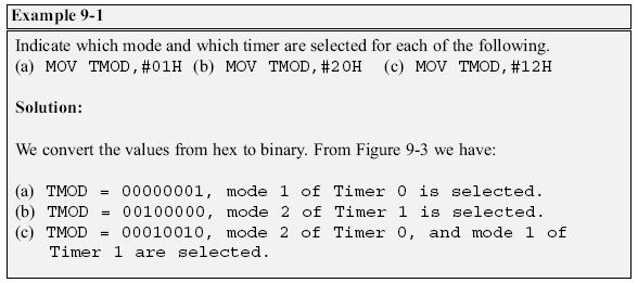
5 TMOD Register Both timers 0 and 1 use the same register, called TMOD (timer mode), to set the various timer operation modes TMOD is a 8-bit register The lower 4 bits are for Timer 0 The upper 4 bits are for Timer 1 In each case, the lower 2 bits are used to set the timer mode The upper 2 bits to specify the operation
6
7
8
 bits TR0 and TR1 The SETB instruction starts it, and it is stopped by the CLR instruction These instructions start and stop the timers as long as GATE=0 in the TMOD")
9 GATE Timers of 8051 do starting and stopping by either software or hardware control In using software to start and stop the timer where GATE=0 The start and stop of the timer are controlled by way of software by the TR (timer start) bits TR0 and TR1 The SETB instruction starts it, and it is stopped by the CLR instruction These instructions start and stop the timers as long as GATE=0 in the TMOD register
 The hardware way of starting and stopping the timer by an")
10 GATE (cont.) The hardware way of starting and stopping the timer by an external source is achieved by making GATE=1 in the TMOD register
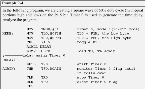
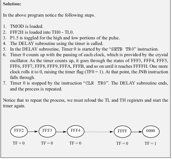
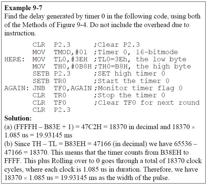
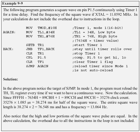
11 Mode 1 Programming The following are the characteristics and operations of mode1: It is a 16-bit timer It allows value of 0000 to FFFFH to be loaded into the timer s register TL and TH After TH and TL are loaded with a 16-bit initial value, the timer must be started This is done by SETB TR0 for timer 0 and SETB TR1 for timer 1 After being started, it starts to count up It counts up until it reaches its limit of FFFFH
 When it rolls over from FFFFH to 0000, it sets high a flag bit called TF (timer flag) Each timer has its own timer flag: TF0 for timer 0, and TF1 for timer 1 This timer flag can be monitored When")
12 Mode 1 Programming (cont.) When it rolls over from FFFFH to 0000, it sets high a flag bit called TF (timer flag) Each timer has its own timer flag: TF0 for timer 0, and TF1 for timer 1 This timer flag can be monitored When this timer flag is raised, one option would be to stop the timer with the instructions CLR TR0 or CLR TR1, for timer 0 and timer 1, respectively In order to repeat the process TH and TL must be reloaded with the original value TF must be reloaded to 0
13 Steps to Mode 1 Program Load the TMOD value register Indicating which timer (timer 0 or timer 1) is to be used and which timer mode (0 or 1) is selected Load registers TL and TH with initial count value Start the timer Keep monitoring the timer flag (TF) With the JNB TFx,target instruction to see if it is raised
14 Steps to Mode 1 Program (cont.) Get out of the loop when TF becomes high Stop the timer Clear the TF flag for the next round Go back to Step 2 to load TH and TL again
15
16
17
18
19

20 If TH and TL are not reloaded. the program generates a single pulse.
21

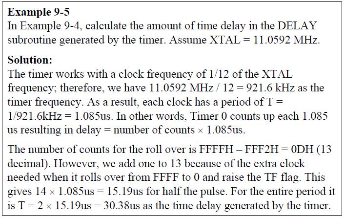
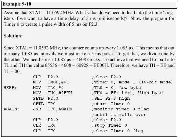
22 Finding the Loaded Timer Values To calculate the values to be loaded into the TL and TH registers: Assume XTAL = MHz Divide the desired time delay by us Perform n, where n is the decimal value we got in Step1 Convert the result of Step2 to hex, where yyxx is the initial hex value to be loaded into the timer s register Set TL = xx and TH = yy
23
24
25

26
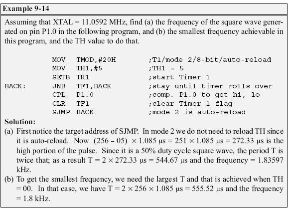
27 Mode 2 Programming The following are the characteristics and operations of mode 2: It is an 8-bit timer It allows only values of 00 to FFH to be loaded into the timer s register TH After TH is loaded with the 8-bit value, the 8051 gives a copy of it to TL Then the timer must be started This is done by the instruction SETB TR0 for timer 0 and SETB TR1 for timer 1
28 Mode 2 Programming (cont.) After the timer is started, it starts to count up by incrementing the TL register It counts up until it reaches its limit of FFH When it rolls over from FFH to 00, it sets high the TF (timer flag) When TF is set to 1, TL is reloaded automatically with the original value kept by the TH register To repeat the process, we must simply clear TF and let it go without any need by the programmer to reload the original value
 Mode 2 can auto-reload, in contrast with mode 1 in which")
29 Mode 2 Programming (cont.) Mode 2 can auto-reload, in contrast with mode 1 in which the programmer has to reload TH and TL
30 Steps to Mode 2 Program Load the TMOD value register Indicating which timer (timer 0 or timer 1) is to be used, and the timer mode (mode 2) is selected Load the TH registers with the initial count value Start timer Keep monitoring the timer flag (TF) With the JNB TFx,target instruction to see whether it is raised
31 Steps to Mode 2 Program (cont.) Get out of the loop when TF goes high Clear the TF flag Go back to Step 4 Since mode 2 is auto-reload
32
33

34 The number 200 is the timer count till the TF is set to 1
35 Counter Programming Timers can also be used as counters Counting events happening outside the 8051 A pulse outside of the 8051 increments the TH, TL registers TMOD and TH, TL registers are the same as for the timer Programming the timer also applies to programming it as a counter Except the source of the frequency The C/T bit in the TMOD registers decides the source of the clock for the timer
 When C/T = 1, the timer is used as a counter and gets its pulses from outside the 8051 The counter counts up as")
36 Counter Programming (cont.) When C/T = 1, the timer is used as a counter and gets its pulses from outside the 8051 The counter counts up as pulses are fed from pins 14 and 15 These pins are called T0 (timer 0 input) and T1 (timer 1 input)
37
38
 register is an 8-bit")
39 TCON Register TCON (timer control) register is an 8-bit register
 TCON register is a")
40 TCON Register (cont.) TCON register is a bit-addressable register
41 Case of GATE = 1 The start and stop of the timer are done externally through pins P3.2 and P3.3 for timers 0 and 1, respectively Allows to start or stop the timer externally at any time via a simple switch
ELEG3923 Microprocessor Ch.9 Timer Programming
 Department of Electrical Engineering University of Arkansas ELEG3923 Microprocessor Ch.9 Timer Programming Dr. Jingxian Wu wuj@uark.edu OUTLINE 2 Programming 8051 Timers Counter programming Timer programming
The 8051 microcontroller has two 16-bit timers/counters called T0 and T1.
 Counters and Timers: The 8051 microcontroller has two 16-bit timers/counters called T0 and T1. As their names suggest, timer counts internal clock pulse i.e. machine cycle to provide delay. Counter counts
8051 Timers. Class 7 EE4380 Fall Pari vallal Kannan. Center for Integrated Circuits and Systems University of Texas at Dallas
 8051 Timers Class 7 EE4380 Fall 2002 Pari vallal Kannan Center for Integrated Circuits and Systems University of Texas at Dallas Introduction Timers Timing devices - Generate specific time delay Event
Chapter 09. Programming in Assembly
 Chapter 09 Programming in Assembly Lesson 05 Programming Examples for Timers Programming TMOD Register 3 Write instructions to run T0 in Mode 0, external count inputs, internal start/stop control ANL TMOD,
8051 Peripherals. On-Chip Memory Timers Serial Port Interrupts. Computer Engineering Timers
 8051 Peripherals On-Chip Memory Timers Serial Port Interrupts Computer Engineering 2 2-1 8051 Timers 8051 Timers The 8051 has 2 internal 16-bit timers named Timer 0 and Timer 1 Each timer is a 16-bit counter
Department of EIE / Pondicherry Engineering College. Timer/Counters. Department of EIE / Pondicherry Engineering College 1
 Timer/Counters Department of EIE / Pondicherry Engineering College 1 The 8051 has two internal sixteen bit hardware Timer/Counters. Each Timer/Counter can be configured in various modes, typically based
CPEG300 Embedded System Design. Lecture 8 Timer
 CPEG300 Embedded System Design Lecture 8 Timer Hamad Bin Khalifa University, Spring 2018 Review 8051 port and port schematic Internal read/write data path Serial communication vs. parallel communication
Timers and interrupts
 Timers and interrupts CSCI 255: Introduction to Embedded Systems Keith Vertanen Copyright 2011 Timers Overview Creating fixed pauses Calculate length of events Counts events Generate baud rate for serial
8051 Timers and Serial Port
 8051 Timers and Serial Port EE4380 Fall 2001 Class 10 Pari vallal Kannan Center for Integrated Circuits and Systems University of Texas at Dallas Timer: Mode 1 Operation (recap) 16 bit counter. Load the
Timer programming
 5.8051 Timer programming In this tutorial, we are going to discuss the Timer module of 8051. First, we will see what are timers, their working and later we will configure the 8051 timers to generate the
Mod-3: Interrupts,Timer operation,serial communication 1
 Mod-3: Interrupts,Timer operation,serial communication 1 Module-3 Contents: Interrupts - interrupt sources - interrupt handling programming examples. Timers operation different modes waveform generation-
Interrupts. EE4380 Fall 2001 Class 9. Pari vallal Kannan. Center for Integrated Circuits and Systems University of Texas at Dallas
 8051 - Interrupts EE4380 Fall 2001 Class 9 Pari vallal Kannan Center for Integrated Circuits and Systems University of Texas at Dallas Polling Vs Interrupts Polling: MCU monitors all served devices continuously,
 اصول ميکروکامپيوترها استاد درس: دکتر http://ee.iust.ac.ir/rahmati/index.htm rahmati@iust.ac.ir ا درس Email و Website برای تکاليف و... : http://eel.iust.ac.ir/rahmati/ ١ هجدهم فصل ا شنايی با تايمرهای 8051
e-pg Pathshala Subject : Computer Science Paper: Embedded System Module: Interrupt Handling Module No: CS/ES/13 Quadrant 1 e-text
 e-pg Pathshala Subject : Computer Science Paper: Embedded System Module: Interrupt Handling Module No: CS/ES/13 Quadrant 1 e-text 1. Interrupt An interrupt is the occurrence of a condition--an event --
2. Write an 8051 program to generate a square wave of 25 khz at pin P2.3 using XTAL = 12 MHz. Solution:
 Assignment 2 1. Assume that 5 binary data items are stored in RAM locations starting at 50h, as shown below. Write a program to find the sum of all the numbers. The calculation is in 16-bit format and
MICROPROCESSORS AND MICROCONTROLLERS MATERIAL. Features of 8051:
 DEPARTMENT OF ECE MICROPROCESSORS AND MICROCONTROLLERS MATERIAL UNIT V 8051 MICROCONTROLLERS To make a complete microcomputer system, only microprocessor is not sufficient. It is necessary to add other
FACULTY OF ENGINEERING LAB SHEET
 FACULTY OF ENGINEERING LAB SHEET MICROCONTROLLER AND MICROPROCESSOR SYSTEMS ECE2216 TRIMESTER 1 (2017/2018) MP2: Construction and programming of a basic electronic piano *Note: On-the-spot evaluation may
MCS-51 Serial Port A T 8 9 C 5 2 1
 MCS-51 Serial Port AT89C52 1 Introduction to Serial Communications Serial vs. Parallel transfer of data Simplex, Duplex and half-duplex modes Synchronous, Asynchronous UART Universal Asynchronous Receiver/Transmitter.
MODEL ANSWER SUBJECT- MICROCONTROLLER(12187) CLASS-EJ5E CLASS TEST-02 Q1.)Attempt any THREE of the following.
 CLASS-EJ5E CLASS TEST-02 Q1.)Attempt any THREE of the following.") MODEL ANSWER SUBJECT- MICROCONTROLLER(12187) CLASS-EJ5E CLASS TEST-02 Q1.)Attempt any THREE of the following. (9M) 1) Describe the instructions SWAP A and MOVX@DPTR,A with one example. (3Marks) SWAP A
MODEL ANSWER SUBJECT- MICROCONTROLLER(12187) CLASS-EJ5E CLASS TEST-02 Q1.)Attempt any THREE of the following. (9M) 1) Describe the instructions SWAP A and MOVX@DPTR,A with one example. (3Marks) SWAP A
8051 Microcontroller memory Organization and its Applications
 8051 Microcontroller memory Organization and its Applications Memory mapping in 8051 ROM memory map in 8051 family 0000H 4k 0000H 8k 0000H 32k 0FFFH DS5000-32 8051 1FFFH 8752 7FFFH from Atmel Corporation
CHAPTER 11 INTERRUPTS PROGRAMMING
 CHAPTER 11 INTERRUPTS PROGRAMMING Interrupts vs. Polling An interrupt is an external or internal event that interrupts the microcontroller To inform it that a device needs its service A single microcontroller
8051 Microcontroller
 8051 Microcontroller 1 Salient Features (1). 8 bit microcontroller originally developed by Intel in 1980. (2). High-performance CMOS Technology. (3). Contains Total 40 pins. (4). Address bus is of 16 bit
EE6502- MICROPROCESSOR AND MICROCONTROLLER
 . EE6502- MICROPROCESSOR AND MICROCONTROLLER UNIT III - 8051 MICROCONTROLLER PART - A 1. What is Microcontroller? A device which contains the microprocessor with integrated peripherals like memory, serial
CoE3DJ4 Digital Systems Design. Chapter 5: Serial Port Operation
 CoE3DJ4 Digital Systems Design Chapter 5: Serial Port Operation Serial port 8051 includes an on-chip serial port Hardware access to the port is through TXD and RXD (Port 3 bits 1 and 0) Serial port is
Microcontroller and Embedded Systems:
 Microcontroller and Embedded Systems: Branches: 1. Electronics & Telecommunication Engineering 2. Electrical & Electronics Engineering Semester: 6 th Semester / 7 th Semester 1. Explain the differences
Interrupt Programming: Interrupts vs. Polling Method:
 UNIT 4: INTERRUPT PROGRAMMING & SERIAL COMMUNICATION WITH 8051: Definition of an interrupt, types of interrupts, Timers and Counter programming with interrupts in assembly. 8051 Serial Communication: Data
UNIT IV MICROCONTROLLER
 UNIT IV 8051- MICROCONTROLLER Prepared by R. Kavitha Page 1 Application Prepared by R. Kavitha Page 2 Pin Description of the 8051 UNIT IV- 8051 MICROCONTROLLER P1.0 P1.1 P1.2 P1.3 P1.4 P1.5 P1.6 P1.7 RST
Interrupts, timers and counters
 Interrupts, timers and counters Posted on May 10, 2008, by Ibrahim KAMAL, in Micro-controllers, tagged Most microcontrollers come with a set of ADD-ONs called peripherals, to enhance the functioning of
Introduction To MCS-51
 Introduction To MCS-51 By Charoen Vongchumyen Department of Computer Engineering Faculty of Engineering KMITLadkrabang 8051 Hardware Basic Content Overview Architechture Memory map Register Interrupt Timer/Counter
e-pg Pathshala Subject : Computer Science Paper: Embedded System Module: Serial Port Programming in Assembly Module No: CS/ES/12 Quadrant 1 e-text
 e-pg Pathshala Subject : Computer Science Paper: Embedded System Module: Serial Port Programming in Assembly Module No: CS/ES/12 Quadrant 1 e-text In this lecture, serial communication control register
80C51 Block Diagram. CSE Overview 1
 80C51 Block Diagram CSE 477 8051 Overview 1 80C51 Memory CSE 477 8051 Overview 3 8051 Memory The data width is 8 bits Registers are 8 bits Addresses are 8 bits i.e. addresses for only 256 bytes! PC is
Chapter 3. Bit Addressable Area. By DeccanRobots
 Chapter 3 Bit Addressable Area By DeccanRobots What is Bit Addressable Area? FFh 2Fh 20h 00h Data Memory General purpose Memory Area Bit Addressable Memory Registers Memory Area from 20H to 2FH is Bit
e-pg Pathshala Subject: Computer Science Paper: Embedded System Module: Interrupt Programming in Embedded C Module No: CS/ES/20 Quadrant 1 e-text
 e-pg Pathshala Subject: Computer Science Paper: Embedded System Module: Interrupt Programming in Embedded C Module No: CS/ES/20 Quadrant 1 e-text In this lecture embedded C program for interrupt handling
8051 microcontrollers
 8051 microcontrollers Presented by: Deepak Kumar Rout Synergy Institute of Engineering and Technology, Dhenkanal Chapter 2 Introduction Intel MCS-51 family of microcontrollers consists of various devices
Lesson-3: Counters and Timers
 8051 AND ADVANCED PROCESSOR ARCHITECTURES Lesson-3: Counters and Timers 1 Timing and counting devices Two T0 and T1 in classic 8051 family and three T0, T1 and T2 in 8052 family (an extension of 8051).
INTERRUPTS PROGRAMMING
 INTERRUPTS PROGRAMMING The 8051 Microcontroller and Embedded Systems: Using Assembly and C Mazidi, Mazidi and McKinlay Chung-Ping Young 楊中平 Home Automation, Networking, and Entertainment Lab Dept. of Computer
Lecture 9. Timer Operations and Programming
 Lecture 9 Timer Operations and Programming Timer Operations and Programming Introduction Summary of timers Timer programming sequence Summary of timer SFRs Timer 0-1: 8-bit auto-reload mode (mode 2) Programming
8051 Serial Communication
 8051 Serial Communication Basics of serial communication Parallel: transfers eight bits of data simultaneously over eight data lines expensive - short distance fast Serial : one bit at a time is transferred
8-bit Microcontroller with 8K Bytes In-System Programmable Flash AT89S52
 Features Compatible with MCS -51 Products 8K Bytes of In-System Programmable (ISP) Flash Memory Endurance: 10,000 Write/Erase Cycles 4.0V to 5.5V Operating Range Fully Static Operation: 0 Hz to 33 MHz
SANKALCHAND PATEL COLLEGE OF ENGINEERING, VISNAGAR. ELECTRONICS & COMMUNICATION DEPARTMENT Question Bank- 1
 SANKALCHAND PATEL COLLEGE OF ENGINEERING, VISNAGAR ELECTRONICS & COMMUNICATION DEPARTMENT Question Bank- 1 Subject: Microcontroller and Interfacing (151001) Class: B.E.Sem V (EC-I & II) Q-1 Explain RISC
Timer Counter and Interrupt. Equation (16 bits counter, Mode 1, 16MHz):
:") Equation (16 bits counter, Mode 1, 16MHz): THxTLx = 65536 - (Tt * 16.777216 e6) where: Tt: Target time x: Timer/Counter (0, 1 and 2) THx: Timer high byte TLx: Timer low byte Used Interrupts: 1 (Address,
Equation (16 bits counter, Mode 1, 16MHz): THxTLx = 65536 - (Tt * 16.777216 e6) where: Tt: Target time x: Timer/Counter (0, 1 and 2) THx: Timer high byte TLx: Timer low byte Used Interrupts: 1 (Address,
8051 Serial Port. EE4380 Fall02 Class 10. Pari vallal Kannan. Center for Integrated Circuits and Systems University of Texas at Dallas
 8051 Serial Port EE4380 Fall02 Class 10 Pari vallal Kannan Center for Integrated Circuits and Systems University of Texas at Dallas Serial Comm. - Introduction Serial Vs Parallel Transfer of data Simplex,
Question Bank Microprocessor and Microcontroller
 QUESTION BANK - 2 PART A 1. What is cycle stealing? (K1-CO3) During any given bus cycle, one of the system components connected to the system bus is given control of the bus. This component is said to
8051 Microcontroller
 8051 Microcontroller The 8051, Motorola and PIC families are the 3 leading sellers in the microcontroller market. The 8051 microcontroller was originally developed by Intel in the late 1970 s. Today many
Serial I-O for Dinesh K. Sharma Electrical Engineering Department I.I.T. Bombay Mumbai (version 14/10/07)
") Serial I-O for 8051 Dinesh K. Sharma Electrical Engineering Department I.I.T. Bombay Mumbai 400 076 (version 14/10/07) 1 Motivation Serial communications means sending data a single bit at a time. But
Serial I-O for 8051 Dinesh K. Sharma Electrical Engineering Department I.I.T. Bombay Mumbai 400 076 (version 14/10/07) 1 Motivation Serial communications means sending data a single bit at a time. But
Chapter 6 PROGRAMMING THE TIMERS
 Chapter 6 PROGRAMMING THE TIMERS Reload Start Stop Programmabl e Prescaling Prescaling Loa d Timer-counter Device Reset Internal clock inputs External counting of inputs Free Running Lesson 1 Programmable
The University of Texas at Arlington Lecture 21_Review
 The University of Texas at Arlington Lecture 21_Review CSE 5442/3442 Agenda Tuesday December 1st Hand back Homework 7,8 and 9. Go over questions and answers Exam 3 Review Note: There will be a take home
UNIT 2 THE 8051 INSTRUCTION SET AND PROGRAMMING
 UNIT 2 THE 8051 INSTRUCTION SET AND PROGRAMMING Instructions Alphabetical List of Instructions ACALL: Absolute Call ADD, ADDC: Add Accumulator (With Carry) AJMP: Absolute Jump ANL: Bitwise AND CJNE: Compare
8051 Microcontroller. Ali Ziya Alkar 1
 8051 Microcontroller Ali Ziya Alkar 1 8051 Introduction 8051 is one of the most popular microcontrollers in use today. Many derivative microcontrollers have since been developed that are based on--and
CHAPTER ASSEMBLY LANGUAGE PROGRAMMING
 CHAPTER 2 8051 ASSEMBLY LANGUAGE PROGRAMMING Registers Register are used to store information temporarily: A byte of data to be processed An address pointing to the data to be fetched The vast majority
EEE3410 Microcontroller Applications Department of Electrical Engineering Lecture 4 The 8051 Architecture
 Department of Electrical Engineering Lecture 4 The 8051 Architecture 1 In this Lecture Overview General physical & operational features Block diagram Pin assignments Logic symbol Hardware description Pin
1. Attempt any three of the following: 15
 (2½ hours) Total Marks: 75 N. B.: (1) All questions are compulsory. (2) Make suitable assumptions wherever necessary and state the assumptions made. (3) Answers to the same question must be written together.
8051 MICROCONTROLLER
 8051 MICROCONTROLLER Mr.Darshan Patel M.Tech (Power Electronics & Drives) Assistant Professor Department of Electrical Engineering Sankalchand Patel College of Engineering-Visnagar WHY DO WE NEED TO LEARN
Department of Electronics and Instrumentation Engineering Question Bank
 www.examquestionpaper.in Department of Electronics and Instrumentation Engineering Question Bank SUBJECT CODE / NAME: ET7102 / MICROCONTROLLER BASED SYSTEM DESIGN BRANCH : M.E. (C&I) YEAR / SEM : I / I
CPEG300 Embedded System Design. Lecture 6 Interrupt System
 CPEG300 Embedded System Design Lecture 6 Interrupt System Hamad Bin Khalifa University, Spring 2018 Correction Lecture 3, page 18: Only direct addressing mode is allowed for pushing or popping the stack:
 اصول ميکروکامپيوترها استاد درس: دکتر http://ee.iust.ac.ir/rahmati/index.htm rahmati@iust.ac.ir ا درس Email و Website برای تکاليف و... : http://eel.iust.ac.ir/rahmati/ ١ نوزدهم فصل ا شنايی با دستورالعمل
MAHALAKSHMI ENGINEERING COLLEGE TIRUCHIRAPALLI
 MAHALAKSHMI ENGINEERING COLLEGE TIRUCHIRAPALLI-621213. QUESTION BANK DEPARTMENT: EEE SUB CODE: EE2324 YR/ SEM:III/ VI SUB NAME: MICROPROCESSORS & MICROCONTROLLERS UNIT 4-8051 MICROCONTROLLER PART A (2
Microcontrollers. Fig. 1 gives a comparison of a microprocessor system and a microcontroller system.
 Syllabus: : Introduction to, 8051 Microcontroller Architecture and an example of Microcontroller based stepper motor control system (only Block Diagram approach). (5 Hours) Introduction to A microcontroller
Microcontroller and Applications
 S.Y. Diploma : Sem. IV [DE/EJ/ET/EN/EX/EQ/IS/IC/IE] Microcontroller and Applications Time: 3 Hrs.] Prelim Question Paper Solution [Marks : 70 Q.1 Attempt any FIVE of the following : [10] Q.1(a) Define
Timer-1 can be run using the internal clock, fosc/12 (timer mode) or from any external source via pin T1 (P3.5) (Counter mode).
 or from any external source via pin T1 (P3.5) (Counter mode).") EC 6504 MICROPROCESSOR AND MICROCONTROLLER Electronics and Communication Engineering Fifth Semester UNIT-V Part A 1. List the modes of Timer in 8051. [N/D16] The timers available in 8051 are Timer 0 (T0)
EC 6504 MICROPROCESSOR AND MICROCONTROLLER Electronics and Communication Engineering Fifth Semester UNIT-V Part A 1. List the modes of Timer in 8051. [N/D16] The timers available in 8051 are Timer 0 (T0)
ELEG3923 Microprocessor Ch.10 Serial Port Programming
 Department of Electrical Engineering University of Arkansas ELEG3923 Microprocessor Ch.10 Serial Port Programming Dr. Jingxian Wu wuj@uark.edu OUTLINE 2 Basics of Serial Communication Serial port programming
Q 1 a) Attempt any THREE of the following: 12 TMOD.7 TMOD.6 TMOD.5 TMOD.4 TMOD.3 TMOD.2 TMOD.1 TMOD.0 GATE C/T M1 M0 GATE C/T M1 M0
 Attempt any THREE of the following: 12 TMOD.7 TMOD.6 TMOD.5 TMOD.4 TMOD.3 TMOD.2 TMOD.1 TMOD.0 GATE C/T M1 M0 GATE C/T M1 M0") Page 1 of 33 Q 1 a) Attempt any THREE of the following: 12 Q 1 a i) Describe Timer modes of 8051. Ans: Timer 0 and Timer 1 can both be used as either Counters or Timers. There are 4 different operating
Page 1 of 33 Q 1 a) Attempt any THREE of the following: 12 Q 1 a i) Describe Timer modes of 8051. Ans: Timer 0 and Timer 1 can both be used as either Counters or Timers. There are 4 different operating
1. Pin diagram of 8051 and ports
 e-pg Pathshala Subject : Computer Science Paper: Embedded System Module: Programming parallel ports Module No: CS/ES/9 Quadrant 1 e-text In this lecture pin diagram of 8051 controller will be shown and
MAHARASHTRA STATE BOARD OF TECHNICAL EDUCATION (Autonomous) (ISO/IEC Certified) SUMMER 14 EXAMINATION Model Answer
 (ISO/IEC Certified) SUMMER 14 EXAMINATION Model Answer") MAHARASHTRA STATE BOARD OF TECHNICAL EDUCATION (Autonomous) (ISO/IEC 27001 2005 Certified) SUMMER 14 EXAMINATION Model Answer Subject Code : 12187 Page No: 1/28 Important Instructions to examiners: 1)
MAHARASHTRA STATE BOARD OF TECHNICAL EDUCATION (Autonomous) (ISO/IEC 27001 2005 Certified) SUMMER 14 EXAMINATION Model Answer Subject Code : 12187 Page No: 1/28 Important Instructions to examiners: 1)
WINTER 14 EXAMINATION
 Subject Code: 17534 WINTER 14 EXAMINATION Model Answer Important Instructions to examiners: 1) The answers should be examined by key words and not as word-to-word as given in the model answer scheme. 2)
 Distributed by: www.jameco.com 1-800-831-4242 The content and copyrights of the attached material are the property of its owner. 8051 8052 and 80C51 Hardware Description December 1992 Order Number 270252-006
8051 Core Specification
 8051 Core Specification Authors: Jaka Simsic Simon Teran jakas@opencores.org simont@opencores.org Rev. 0.1 August 14, 2001 First Draft www.opencores.org Rev 0.1 First Draft 1 of 26 Revision History Rev.
ENE 334 Microprocessors
 Page 1 ENE 334 Microprocessors Lecture 9: MCS-51: Moving Data : Dejwoot KHAWPARISUTH http://webstaff.kmutt.ac.th/~dejwoot.kha/ ENE 334 MCS-51 Moving Data Page 2 Moving Data: Objectives Use commands that
Vidyalankar T.E. Sem. V [EXTC] Microprocessors and Microcontrollers I Prelim Question Paper Solution V SS (GND)
![Vidyalankar T.E. Sem. V [EXTC] Microprocessors and Microcontrollers I Prelim Question Paper Solution V SS (GND)](/thumbs/93/114180611.jpg "Vidyalankar T.E. Sem. V [EXTC] Microprocessors and Microcontrollers I Prelim Question Paper Solution V SS (GND)") 1. (a) Pin configuration of 8085 X 1 X 2 CLKOUT TRAP RST 7.5 RST 6.5 RST 5.5 INTR INTA SID SOD RESET IN RESET OUT T.E. Sem. V [EXTC] Microprocessors and Microcontrollers I Prelim Question Paper Solution
1. (a) Pin configuration of 8085 X 1 X 2 CLKOUT TRAP RST 7.5 RST 6.5 RST 5.5 INTR INTA SID SOD RESET IN RESET OUT T.E. Sem. V [EXTC] Microprocessors and Microcontrollers I Prelim Question Paper Solution
The Timers/Counters The Serial Interface The Interrupt System Reset P0.0-P0.7 P2.0-P2.7. Port 2 Drivers. Port 2 Latch
 HARDWARE DESCRIPTION This chapter provides a detailed description of the 80C51 microcontroller (see Figure 1). Included in this description are: The port drivers and how they function both as ports and,
PGT302 Embedded Software Technology. PGT302 Embedded Software Technology
 PGT302 Embedded Software Technology 1 PART 4 Hardware Platform 2 2 Objectives for Part 4 Need to DISCUSS and ANALYZE the following topics: Board (GTUC51B001) specifications startup sequence, bootloader
8051 Microcontrollers
 8051 Microcontrollers Richa Upadhyay Prabhu NMIMS s MPSTME richa.upadhyay@nmims.edu March 8, 2016 Controller vs Processor Controller vs Processor Introduction to 8051 Micro-controller In 1981,Intel corporation
Rev. No. History Issue Date Remark
 Preliminary Bar Code Reader Document Title Bar Code Reader Revision History Rev. No. History Issue Date Remark 0.0 Initial issue June 5, 2000 Preliminary 0.1 Change document title from Bar Code Reader
UNIT THE 8051 INSTRUCTION SET AND PROGRAMMING
 UNIT THE 8051 INSTRUCTION SET AND PROGRAMMING Instructions Alphabetical List of Instructions ACALL: Absolute Call ADD, ADDC: Add Accumulator (With Carry) AJMP: Absolute Jump ANL: Bitwise AND CJNE: Compare
ISSI. IS89C51 CMOS SINGLE CHIP 8-BIT MICROCONTROLLER with 4-Kbytes of FLASH ISSI IS89C51 NOVEMBER 1998 FEATURES GENERAL DESCRIPTION
 IS89C51 CMOS SINGLE CHIP 8-BIT MICROCONTROLLER with 4-Kbytes of FLASH NOVEMBER 1998 FEATURES 80C51 based architecture 4-Kbytes of on-chip Reprogrammable Flash Memory 128 x 8 RAM Two 16-bit Timer/Counters
How to use the PSoC based 16C450 Replacement
 How to use the PSoC based 16C450 Replacement Matthew Burns Eric Ponce August 2017 (Updated April 2018) 1 Overview The PSoC based 16C450 Replacement is intended to replace the 16C450 serial communication
By the end of Class. Outline. Homework 5. C8051F020 Block Diagram (pg 18) Pseudo-code for Lab 1-2 due as part of prelab
 Pseudo-code for Lab 1-2 due as part of prelab") By the end of Class Pseudo-code for Lab 1-2 due as part of prelab Homework #5 on website due before next class Outline Introduce Lab 1-2 Counting Timers on C8051 Interrupts Laboratory Worksheet #05 Copy
By the end of Class Pseudo-code for Lab 1-2 due as part of prelab Homework #5 on website due before next class Outline Introduce Lab 1-2 Counting Timers on C8051 Interrupts Laboratory Worksheet #05 Copy
8051SERIAL PORT PROGRAMMING
 8051SERIAL PORT PROGRAMMING Basics of Serial Communication Computers transfer data in two ways: Parallel Often 8 or more lines (wire conductors) are used to transfer data to a device that is only a few
8-bit Microcontroller with 2/4-Kbyte Flash AT89LP2052 AT89LP4052
 Features Compatible with MCS 51 Products 20 MIPS Throughput at 20 MHz Clock Frequency and 2.4V, 85 C Operating Conditions Single Clock Cycle per Byte Fetch 2/4K Bytes of In-System Programmable (ISP) Flash
VRS540-4kB Flash, 128B RAM, 25~40MHz, 8-Bit MCU
 VRS540-4kB Flash, 28B RAM, 25~40MHz, 8-Bit MCU 34 Ste Catherine Street West, Suite 900, Montreal, Quebec, Canada H3B H4 Tel: (54) 87-2447 http://www.goalsemi.com P.3 P.2 XTAL NC P0./AD VRS540 Overview
VRS550-8kB Flash, 256B RAM, 25~40MHz, 8-Bit MCU VRS560-16kB Flash, 256B RAM, 40MHz, 8-Bit MCU
 VRS550-8kB Flash, 256B RAM, 25~40MHz, 8-Bit MCU VRS560-6kB Flash, 256B RAM, 40MHz, 8-Bit MCU 34 Ste Catherine Street West, Suite 900, Montreal, Quebec, Canada H3B H4 Tel: (54) 87-2447 http://www.goalsemi.com
Embedded Controller Programming
 Embedded Controller Programming Counters, Timers and I/O in Assembly Language Ken Arnold Copyright 2000-2004 Ken Arnold 1 Outline Timer/Counters Serial Port More 8051 Instructions Examples Copyright 2000-2004
JUMP, LOOP AND CALL INSTRUCTIONS
 JUMP, LOOP AND CALL INSTRUCTIONS After you have understood the tutorial on Introduction to assembly language which includes simple instruction sets like input/output operations, now it s time to learn
MODEL ANSWER SUMMER 17 EXAMINATION Subject Title: Microcontroller and Applications Subject Code:
 MODEL ANSWER SUMMER 17 EXAMINATION Subject Title: Microcontroller and Applications Subject Code: I m p o r t a n t I n s t r u c t i o n s t o e x a m i n e r s : 1) The answers should be examined by key
MAHALAKSHMI ENGINEERING COLLEGE TIRUCHIRAPALLI UNIT- IV
 UNIT- IV PART A (2 MARK QUESTIONS) 1. What is the need for de-bouncing the keyboard? (AUC NOV 2012) Debouncing is any kind of hardware device or software that ensures that only a single signal will be
MAHARASHTRA STATE BOARD OF TECHNICAL EDUCATION (Autonomous) (ISO/IEC Certified) Summer 2016 EXAMINATIONS.
 (ISO/IEC Certified) Summer 2016 EXAMINATIONS.") Summer 2016 EXAMINATIONS Subject Code: 17534 Model Answer Important Instructions to examiners: 1) The answers should be examined by key words and not as word-to-word as given in the answer scheme. 2) The
Summer 2016 EXAMINATIONS Subject Code: 17534 Model Answer Important Instructions to examiners: 1) The answers should be examined by key words and not as word-to-word as given in the answer scheme. 2) The
ELEG3923 Microprocessor Ch.4 I/O Ports
 Department of Electrical Engineering University of Arkansas ELEG3923 Microprocessor Ch.4 I/O Ports Dr. Jingxian Wu wuj@uark.edu OUTLINE 2 8051 I/O programming I/O bit manipulation programming I/O PORT
VRS570 32K Flash, 1kB RAM, 25~40MHz, 8-Bit MCU VRS580 64K Flash, 1kB RAM, 25~40MHz, 8-Bit MCU
 VRS570 32K Flash, 1kB RAM, 25~40MHz, 8-Bit MCU VRS580 64K Flash, 1kB RAM, 25~40MHz, 8-Bit MCU 1134 Ste Catherine Street West, Suite 900, Montreal, Quebec, Canada H3B 1H4 Tel: (514) 871-2447 http://www.goalsemi.com
 8051 Memory Organization BY D. BALAKRISHNA, Research Assistant, IIIT-H Chapter 1: Memory Organization There are 2 types of memories available in 8051 microcontroller. Program memory/c code memory (ROM)
MODEL ANSWER SUMMER 17 EXAMINATION
 Important Instructions to examiners: 1) The answers should be examined by key words and not as word-to-word as given in the model answer scheme. 2) The model answer and the answer written by candidate
Q.1. A) Attempt any THREE of the following:
 Attempt any THREE of the following:") Important Instructions to examiners: 1) The answers should be examined by key words and not as word-to-word as given in the model answer scheme. 2) The model answer and the answer written by candidate
Important Instructions to examiners: 1) The answers should be examined by key words and not as word-to-word as given in the model answer scheme. 2) The model answer and the answer written by candidate
Principle and Interface Techniques of Microcontroller
 Principle and Interface Techniques of Microcontroller --8051 Microcontroller and Embedded Systems Using Assembly and C LI, Guang ( 李光 ) Prof. PhD, DIC, MIET WANG, You ( 王酉 ) PhD, MIET 杭州 浙江大学 2014 Chapter
Chapter C2051 Architecture and Serial Communication Link
 Chapter- 2 89C2051 Architecture and Serial Communication Link ABSTRACT This chapter provides the details of 89C2051 microcontroller and description on Serial Communication Facility presented by 89C2051
T.Y. Diploma : Sem. V [EJ/EN/ET/EX/DE/IS/IC/IE/EV/MU] Micro-controller
![T.Y. Diploma : Sem. V [EJ/EN/ET/EX/DE/IS/IC/IE/EV/MU] Micro-controller](/thumbs/84/89719419.jpg "T.Y. Diploma : Sem. V [EJ/EN/ET/EX/DE/IS/IC/IE/EV/MU] Micro-controller") T.Y. Diploma : Sem. V [EJ/EN/ET/EX/DE/IS/IC/IE/EV/MU] Microcontroller Time : 3 Hrs.] Prelim Question Paper Solution [Marks : 100 Q.1(a) Attempt any THREE of the following: [12] Q.1(a) (i) Distinguish between
T.Y. Diploma : Sem. V [EJ/EN/ET/EX/DE/IS/IC/IE/EV/MU] Microcontroller Time : 3 Hrs.] Prelim Question Paper Solution [Marks : 100 Q.1(a) Attempt any THREE of the following: [12] Q.1(a) (i) Distinguish between
MODULE-1. Short Answer Questions
 MODULE-1 Short Answer Questions 1. Give the comparison between microprocessor and microcontroller. It is very clear from figure that in microprocessor we have to interface additional circuitry for providing
AN108 IMPLEMENTING A REALTIME CLOCK. Relevant Devices. Introduction. Key Points. Overview
 IMPLEMENTING A REALTIME CLOCK Relevant Devices This application note applies to the following devices: C8051F000, C8051F001, C8051F002, C8051F005, C8051F006, C8051F007, C8051F010, C8051F011, and C8051F012.
8XC51RA RB RC Hardware Description
 8XC51RA RB RC Hardware Description February 1995 Order Number 272668-001 Information in this document is provided in connection with Intel products Intel assumes no liability whatsoever including infringement
MODEL ANSWER SUMMER 17 EXAMINATION Subject Title: Microcontroller Subject Code:
 MODEL ANSWER SUMMER 17 EXAMINATION Subject Title: Microcontroller Subject Code: 17534 Important Instructions to examiners: 1) The answers should be examined by key words and not as word-to-word as given
Chapter 2. Overview of Architecture and Microcontroller-Resources
 Chapter 2 Overview of Architecture and Microcontroller-Resources Lesson 4 Timers, Real Time Clock Interrupts and Watchdog Timer 2 Microcontroller-resources Port P1 Port P0 Port P2 PWM Timers Internal Program
Fig 1. Block diagram of a microcomputer
 MICRO CONTROLLERS www.bookspar.com VTU NOTES QUESTION PAPERS UNIT - 1 Computer: A computer is a multipurpose programmable machine that reads binary instructions from its memory, accepts binary data as