Chapter 10. Object-Oriented Analysis and Modeling Using the UML. McGraw-Hill/Irwin
|
|
|
- Scot Morgan
- 5 years ago
- Views:
Transcription


1 Chapter 10 Object-Oriented Analysis and Modeling Using the UML McGraw-Hill/Irwin Copyright 2007 by The McGraw-Hill Companies, Inc. All rights reserved.
2 Objectives 10-2 Define object modeling and explain its benefits. Recognize and understand the basic concepts and constructs of object modeling. Define the UML and its various types of diagrams. Evolve a business requirements use-case model into a system analysis use-case model. Construct an activity diagram. Discover objects and classes, and their relationships. Construct a class diagram.
3 10-3
4 Introduction to Object Modeling Object-oriented analysis (OOA) an approach used to 1. study existing objects to see if they can be reused or adapted for new uses 2. define new or modified objects that will be combined with existing objects into a useful business computing application Object modeling a technique for identifying objects within the systems environment and the relationships between those objects. 10-4
5 Introduction to the UML Unified Modeling Language (UML) a set of modeling conventions that is used to specify or describe a software system in terms of objects. The UML does not prescribe a method for developing systems only a notation that is now widely accepted as a standard for object modeling. 10-5
6 Objects & Attributes Object something that is or is capable of being seen, touched, or otherwise sensed, and about which users store data and associate behavior. Person, place, thing, or event Employee, customer, instructor, student Warehouse, office, building, room Product, vehicle, computer, videotape Attribute the data that represent characteristics of interest about an object. 10-6

7 Objects & Object Instances Object instance each specific person, place, thing, or event, as well as the values for the attributes of that object. 10-7
8 Behavior & Encapsulation Behavior the set of things that the object can do that correspond to functions that act on the object s data (or attributes). In object-oriented circles, an object s behavior is commonly referred to as a method, operation, or service. Encapsulation the packaging of several items together into one unit. 10-8
9 Object Classes Object Class a set of objects that share common attributes and behavior. Sometimes referred to as a class. 10-9

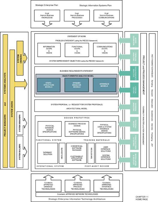
10 10-10 Representing Object Classes in the UML
11 Inheritance Inheritance the concept wherein methods and/or attributes defined in an object class can be inherited or reused by another object class

12 10-12 Inheritance (cont.)
13 Generalization/Specialization, Supertype, and Subtype Generalization/specialization technique wherein attributes and behaviors common to several types of object classes are grouped (or abstracted) into their own class, called a supertype. Supertype an entity that contains attributes and behaviors that are common to one or more class subtypes. Also referred to as abstract or parent class. Subtype an object class that inherits attributes and behaviors from a supertype class and may contain other attributes and behaviors unique to it. Also referred to as a child class and, if it exists at the lowest level of the inheritance hierarchy, as concrete class
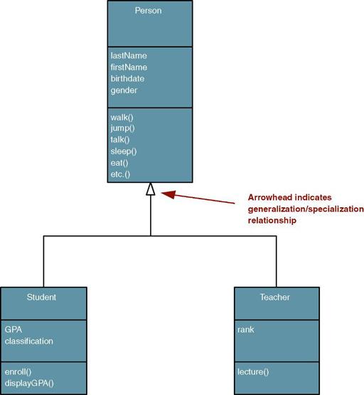
14 10-14 UML Representation of Generalization/Specialization

15 Object/Class Relationships Object/class relationship a natural business association that exists between one or more objects and classes

16 UML Multiplicity Notations Multiplicity the minimum and maximum number of occurrences of one object/class for a single occurrence of the related object/class

17 Aggregation Aggregation a relationship in which one larger whole class contains one or more smaller parts classes. Conversely, a smaller part class is part of a whole larger class In UML 2.0 the notation for aggregation has been dropped 10-17
18 Composition Composition an aggregation relationship in which the whole is responsible for the creation and destruction of its parts. If the whole were to die, the part would die with it
 to request information or some action")
19 Messages Message communication that occurs when one object invokes another object s method (behavior) to request information or some action 10-19
 uses an attribute or behavior of its own instead of an attribute or behavior")
20 Polymorphism Polymorphism the concept that different objects can respond to the same message in different ways Override a technique whereby a subclass (subtype) uses an attribute or behavior of its own instead of an attribute or behavior inherited from the class (supertype).
21 UML 2.0 Diagrams Diagram Use Case Activity Class Object State Machine Composite Structure Description Depicts interactions between the system and external systems and users. In other words it graphically describes who will use the system and in what ways the user expects to interact with the system. The use-case narrative is used in addition to textually describe the sequence of steps of each interaction. Depicts sequential flow of activities of a use case or business process. It can also be used to model logic with the system. Depicts the system's object structure. It shows object classes that the system is composed of as well as the relationships between those object classes. Similar to a class diagram, but instead of depicting object classes, it models actual object instances with current attribute values. The object diagram provides the developer with a "snapshot" of the system's object at one point in time. Models how events can change the state of an object over its lifetime, showing both the various states that an object can assume and the transitions between those states. Decomposes internal structure of class, component, or use case.
22 UML 2.0 Diagrams (cont.) Diagram Sequence Communication Interaction Overview Timing Component Deployment Package Description Graphically depicts how objects interact with each other via messages in the execution of a use case or operation. It illustrates how messages are sent and received between objects and in what sequence. (Collaboration diagram in UML 1.X) Depicts interaction of objects via messages. While a sequence diagram focuses on the timing or sequence of messages, a communication diagram focuses on the structural organization of objects in a network format. Combines features of sequence and activity diagrams to show how objects interact within each activity of a use case. Another interaction diagram that focuses on timing constraints in the changing state of a single object or group of objects. Especially useful when designing embedded software for devices. Depicts the organization of programming code divided into components and how the components interact. Depicts the configuration of software components within the physical architecture of the system's hardware "nodes." Depicts how classes or other UML constructs are organized into packages (corresponding to Java packages or C++ and.net namespaces) and the dependencies of those packages.
23 The Process of Object Modeling 1. Modeling the functions of the system. 2. Finding and identifying the business objects. 3. Organizing the objects and identifying their relationships
24 Construction the Analysis Use-Case Model System analysis use case a use case that documents the interaction between the system user and the system. It is highly detailed in describing what is required but is free of most implementation details and constraints Identify, define, and document new actors. 2. Identify, define, and document new use cases. 3. Identify any reuse possibilities. 4. Refine the use-case model diagram (if necessary). 5. Document system analysis use-case narratives.

25 10-25 Revised System Use-Case Model Diagram

26 10-26 Use-Case Narrative

27 10-27 Use-Case Narrative (cont.)

28 10-28 Abstract Use-Case Narrative
29 Modeling Use-Case Activities Activity diagram a diagram that can be used to graphically depict the flow of a business process, the steps of a use case, or the logic of an object behavior (method)
30 Activity Diagram Notations Initial node - solid circle representing the start of the process. 2. Actions rounded rectangles representing individual steps. The sequence of actions make up the total activity shown by the diagram. 3. Flow - arrows on the diagram indicating the progression through the actions. Most flows do not need words to identify them unless coming out of decisions. 4. Decision - diamond shapes with one flow coming in and two or more flows going out. The flows coming out are marked to indicate the conditions. 5. Merge - diamond shapes with multiple flows coming in and one flow going out. This combines flows previously separated by decisions. Processing continues with any one flow coming into the merge.
31 10-31 Activity Diagram Notations (cont.) 6. Fork a black bar with one flow coming in and two or more flows going out. Actions on parallel flows beneath the fork can occur in any order or concurrently. 7. Join a black bar with two or more flows coming in and one flow going out, noting the end of concurrent processing. All actions coming into the join must be completed before processing continues. 8. Activity final the solid circle inside the hollow circle representing the end of the process.
32 Activity Diagram with Partitions Subactivity indicator the rake symbol in an action indicates that this action is broken out in another separate activity diagram. This helps you keep the activity diagram from becoming overly complex. 10.Connector A letter inside a circle gives you another tool for managing complexity. A flow coming into a connector jumps to the flow coming out of a connector with a matching letter.
33 Guidelines for Constructing Activity Diagrams Start with one initial node as a starting point. Add partitions if it is relevant to your analysis. Add an action for each major step of the use case (or each major step an actor initiates. Add flows from each action to another action, a decision point, or an end point. For maximum precision of meaning, each action should have only one flow coming in and one flow going out with all forks, joins, decisions, and merges shown explicitly. Add decisions where flows diverge with alternating routes. Be sure to bring them back together with a merge. Add forks and joins where activities are performed in parallel. End with a single notation for activity final.
34 Drawing System Sequence Diagrams System sequence diagram - a diagram that depicts the interaction between an actor and the system for a use case scenario. helps identify high-level messages that enter and exit the system 10-34
35 10-35 System Sequence Diagram Notations 1. Actor - the initiating actor of the use case is shown with the use case actor symbol. 2. System the box indicates the system as a "black box" or as a whole. The colon (:) is standard sequence diagram notation to indicate a running "instance" of the system. 3. Lifelines the dashed vertical lines extending downward from the actor and system symbols, which indicate the life of the sequence. 4. Activation bars the bars set over the lifelines indicate period of time when participant is active in the interaction.
36 10-36 System Sequence Diagram Notations (cont.) 5. Input messages - horizontal arrows from actor to system indicate the message inputs. UML convention for messages is to begin the first word with a lowercase letter and add additional words with initial uppercase letter and no space. In parentheses include parameters, following same naming convention and separated with commas. 6. Output messages horizontal arrows from system to actor shown as dashed lines. Since they are web forms, reports, s, etc. these messages do not need to use the standard notation.
37 System Sequence Diagram Notations (cont.) Receiver Actor other actors or external systems that receive messages from the system can be included. 8. Frame a box can enclose one or more messages to divide off a fragment of the sequence. These can show loops, alternate fragments, or optional (opt) steps. For an optional fragment the condition shown in square brackets indicates the conditions under which the steps will be performed.
38 Guidelines for Constructing System Sequence Diagrams Identify which scenario of use case you will depict. Purpose is to discover messages, not to model logic. So more important to clearly communicate a single scenario. Draw a rectangle representing the system as a whole and extend a lifeline under it. Identify each actor who directly provides an input to the system or directly receives an output from the system. Extend lifelines under the actor(s). Examine use case narrative to identify system inputs and outputs. Ignore messages inside system. Draw each external message as a horizontal arrow from the actor's lifeline to the system or from the system to the actor. Label inputs according to UML convention. Add frames to indicate optional messages with conditions. Frames can also indicate loops and alternate fragments. Confirm that the messages are shown in the proper sequence from top to bottom.
39 Finding and Identifying the Business Objects Find the Potential Objects Review each use case to find nouns that correspond to business entities or events. 2. Select the Proposed Objects Not all nouns represent business objects. Is it a synonym of another object? Is it outside the scope of the system? Is it a role without unique behavior, or an external role? Is it unclear or in need of focus? Is it an action or an attribute that describes another object?
40 Partial Use-Case Narrative with Nouns Highlighted DESCRIPTION: PRE-CONDITION: TRIGGER: This use case describes the event of a member submitting a new order for SoundStage products via the world wide web. The member selects the items they wish to purchase. Once they have completed their shopping, the member s demographic information as well as their account standing will be validated. Once the products are verified as being in stock, a packing order is sent to the distribution center for them to prepare the shipment. For any product not in stock, a back order is created. On completion, the member will be sent an order confirmation. The individual submitting the order must be an active club member. The member must login in to the system (provide identification) to enter an order. This use case is initiated when the member selects the option to enter a new order. TYPICAL COURSE Actor Action System Response OF EVENTS: Step 1: The member requests the option to enter a new order. Step 3: The Member browses the available items and selects the ones they wish to purchase along with the quantity. Step 5: The member verifies demographic information (shipping and billing addresses). If no changes are necessary they respond accordingly (to continue). Step 7: The member verifies the order. If no changes are necessary they respond accordingly (to continue). Step 2: The system responds by displaying the catalogue of the SoundStage products. Step 4: Once the member has completed their selections the system retrieves from file and presents the member s demographic information (shipping and billing addresses). Step 6: For each product ordered, the system verifies the product availability and determines an expected ship date, determines the price to be charged to the member, and determines the cost of the total order. If an item is not immediately available it indicates that the product is backordered or that it has not been released for shipping (for pre-orders). If an item is no longer available that is indicated also. The system then displays a summary of the order to the member for verification. Step 8: The system checks the status of the member s account. If satisfactory, the system prompts the member to select the desired payment option (to be billed later or pay immediately with a credit card).

41 10-41 Potential Object List

42 10-42 Cleaning Up List of Candidate Objects

43 10-43 Proposed Object List
44 Organizing the Objects and Identifying their Relationships 1. Identifying Associations and Multiplicity 2. Identifying Generalization/Specialization Relationships 3. Identifying Aggregation Relationships 4. Prepare the Class Diagram Class diagram a graphical depiction of a system s static object structure, showing object classes that the system is composed of as well as the relationships between those object classes.

45 10-45 Object Association Matrix
46 10-46 Generalization/Specialization Hierarchies
47 Persistent and Transient Object Classes Persistent class a class that describes an object that outlives the execution of the program that created it. Stored permanently as in a database Transient object class a class that describes an object that is created temporarily by the program and lives only during that program s execution
48 Class Diagram Refer to Figure in text for a more readable copy
Object-Oriented Systems Analysis and Design Using UML
 10 Object-Oriented Systems Analysis and Design Using UML Systems Analysis and Design, 8e Kendall & Kendall Copyright 2011 Pearson Education, Inc. Publishing as Prentice Hall Learning Objectives Understand
Object-Oriented Design and Modeling Using the UML
 Design Classes Object-Oriented Design and Modeling Using the UML Based on Chapter 18 of Whitten, Bentley, and Dittman: Systems Analysis and Design for the Global Enterprise (7th Ed). McGraw Hill. 2007
CS 370 REVIEW: UML Diagrams D R. M I C H A E L J. R E A L E F A L L
 CS 370 REVIEW: UML Diagrams D R. M I C H A E L J. R E A L E F A L L 2 0 1 5 Introduction UML Unified Modeling Language Very well recognized specification for modeling architectures, use cases, etc. UML
Class diagrams. Modeling with UML Chapter 2, part 2. Class Diagrams: details. Class diagram for a simple watch
 Class diagrams Modeling with UML Chapter 2, part 2 CS 4354 Summer II 2015 Jill Seaman Used to describe the internal structure of the system. Also used to describe the application domain. They describe
Modeling with UML. (1) Use Case Diagram. (2) Class Diagram. (3) Interaction Diagram. (4) State Diagram
 Use Case Diagram. (2) Class Diagram. (3) Interaction Diagram. (4) State Diagram") Modeling with UML A language or notation intended for analyzing, describing and documenting all aspects of the object-oriented software system. UML uses graphical notations to express the design of software
Modeling with UML A language or notation intended for analyzing, describing and documenting all aspects of the object-oriented software system. UML uses graphical notations to express the design of software
Activity Diagram Written Date : September 02, 2016
 Written Date : September 02, 2016 s describe how activities are coordinated to provide a service which can be at different levels of abstraction. Typically, an event needs to be achieved by some operation,
Unified Modeling Language (UML)
") 1 / 45 Unified Modeling Language (UML) Miaoqing Huang University of Arkansas 2 / 45 Outline 1 Introduction 2 Use Case Diagram 3 Class Diagram 4 Sequence Diagram 3 / 45 Outline 1 Introduction 2 Use Case
1 / 45 Unified Modeling Language (UML) Miaoqing Huang University of Arkansas 2 / 45 Outline 1 Introduction 2 Use Case Diagram 3 Class Diagram 4 Sequence Diagram 3 / 45 Outline 1 Introduction 2 Use Case
Interactions A link message
 Interactions An interaction is a behavior that is composed of a set of messages exchanged among a set of objects within a context to accomplish a purpose. A message specifies the communication between
IS 0020 Program Design and Software Tools
 1 IS 0020 Program Design and Software Tools Unified Modeling Language Lecture 13 April 13, 2005 What is UML? 2 The Unified Modelling Language is a standard notation to model [object oriented] systems.
Credit where Credit is Due. Lecture 4: Fundamentals of Object Technology. Goals for this Lecture. Real-World Objects
 Lecture 4: Fundamentals of Object Technology Kenneth M. Anderson Object-Oriented Analysis and Design CSCI 6448 - Spring Semester, 2003 Credit where Credit is Due Some material presented in this lecture
Meltem Özturan
 Meltem Özturan www.mis.boun.edu.tr/ozturan/samd 1 2 Modeling System Requirements Object Oriented Approach to Requirements OOA considers an IS as a set of objects that work together to carry out the function.
Unified Modeling Language (UML) Class Diagram
 Class Diagram") 1 / 10 Unified Modeling Language (UML) Class Diagram Miaoqing Huang University of Arkansas Spring 2010 2 / 10 Outline 1 2 3 / 10 Class Diagram Class diagrams show the static structure of the classes that
1 / 10 Unified Modeling Language (UML) Class Diagram Miaoqing Huang University of Arkansas Spring 2010 2 / 10 Outline 1 2 3 / 10 Class Diagram Class diagrams show the static structure of the classes that
Unified Modeling Language (UML) and Modeling
 and Modeling") LECTURE-11 Unified Modeling Language (UML) and Modeling UML is a graphical notation useful for OO analysis and design Allows representing various aspects of the system Various notations are used to build
LECTURE-11 Unified Modeling Language (UML) and Modeling UML is a graphical notation useful for OO analysis and design Allows representing various aspects of the system Various notations are used to build
Lesson 11. W.C.Udwela Department of Mathematics & Computer Science
 Lesson 11 INTRODUCING UML W.C.Udwela Department of Mathematics & Computer Science Why we model? Central part of all the activities We build model to Communicate Visualize and control Better understand
Basic Structural Modeling. Copyright Joey Paquet,
 Basic Structural Modeling Copyright Joey Paquet, 2000 1 Part I Classes Copyright Joey Paquet, 2000 2 Classes Description of a set of objects sharing the same attributes, operations and semantics Abstraction
UML. By Somenath Mukhopadhyay.
 UML By som@som-itsolutions.com What is the UML? Stands for unified modelling language Is the successor of OOAD methods It unifies the methods of Booch, Rumbaugh and Jacobson Now a standard with Object
UML- a Brief Look UML and the Process
 UML- a Brief Look UML grew out of great variety of ways Design and develop object-oriented models and designs By mid 1990s Number of credible approaches reduced to three Work further developed and refined
Oral Questions. Unit-1 Concepts. Oral Question/Assignment/Gate Question with Answer
 Unit-1 Concepts Oral Question/Assignment/Gate Question with Answer The Meta-Object Facility (MOF) is an Object Management Group (OMG) standard for model-driven engineering Object Management Group (OMG)
Practical UML : A Hands-On Introduction for Developers
 Borland.com Borland Developer Network Borland Support Center Borland University Worldwide Sites Login My Account Help Search Practical UML : A Hands-On Introduction for Developers - by Randy Miller Rating:
Software Service Engineering
 Software Service Engineering Lecture 4: Unified Modeling Language Doctor Guangyu Gao Some contents and notes selected from Fowler, M. UML Distilled, 3rd edition. Addison-Wesley Unified Modeling Language
Class diagrams. Modeling with UML Chapter 2, part 2. Class Diagrams: details. Class diagram for a simple watch
 Class diagrams Modeling with UML Chapter 2, part 2 CS 4354 Summer II 2014 Jill Seaman Used to describe the internal structure of the system. Also used to describe the application domain. They describe
Goal: build an object-oriented model of the realworld system (or imaginary world) Slicing the soup: OOA vs. OOD
 Slicing the soup: OOA vs. OOD") Domain analysis Goal: build an object-oriented model of the realworld system (or imaginary world) Slicing the soup: OOA vs. OOD OOA concerned with what, not how OOA activities focus on the domain layer
Domain analysis Goal: build an object-oriented model of the realworld system (or imaginary world) Slicing the soup: OOA vs. OOD OOA concerned with what, not how OOA activities focus on the domain layer
Practical UML - A Hands-On Introduction for Developers
 Practical UML - A Hands-On Introduction for Developers By: Randy Miller (http://gp.codegear.com/authors/edit/661.aspx) Abstract: This tutorial provides a quick introduction to the Unified Modeling Language
INTRODUCTION TO UNIFIED MODELING MODEL (UML) & DFD. Slides by: Shree Jaswal
 & DFD. Slides by: Shree Jaswal") INTRODUCTION TO UNIFIED MODELING MODEL (UML) & DFD Slides by: Shree Jaswal What is UML? 2 It is a standard graphical language for modeling object oriented software. It was developed in mid 90 s by collaborative
INTRODUCTION TO UNIFIED MODELING MODEL (UML) & DFD Slides by: Shree Jaswal What is UML? 2 It is a standard graphical language for modeling object oriented software. It was developed in mid 90 s by collaborative
LABORATORY 1 REVISION
 UTCN Computer Science Department Software Design 2012/2013 LABORATORY 1 REVISION ================================================================== I. UML Revision This section focuses on reviewing the
STATE MACHINES. Figure 1: State Machines
 STATE MACHINES Figure 1: State Machines state machine A state machine is a behavior that specifies the sequences of states an object goes through during its lifetime in response to events. Graphically,
UNIT-4 Behavioral Diagrams
 UNIT-4 Behavioral Diagrams P. P. Mahale Behavioral Diagrams Use Case Diagram high-level behaviors of the system, user goals, external entities: actors Sequence Diagram focus on time ordering of messages
Unit Wise Questions. Unit-1 Concepts
 Unit Wise Questions Unit-1 Concepts Q1. What is UML? Ans. Unified Modelling Language. It is a Industry standard graphical language for modelling and hence visualizing a blue print of all the aspects of
MAHARASHTRA STATE BOARD OF TECHNICAL EDUCATION (Autonomous) (ISO/IEC Certified)
 (ISO/IEC Certified)") Subject Code: 17630 Model Answer Page No: 1 /32 Important Instructions to examiners: 1) The answers should be examined by keywords and not as word-to-word as given in the model answer scheme. 2) The model
Subject Code: 17630 Model Answer Page No: 1 /32 Important Instructions to examiners: 1) The answers should be examined by keywords and not as word-to-word as given in the model answer scheme. 2) The model
UML Views of a System
 UML Views of a System The architecture of a system is the fundamental organization of the system as a whole. The five UML Views: Use Case View: focuses on scenarios Design View: focuses on the vocabulary
Data and Process Modeling
 Data and Process Modeling Chapter 3 Data Models Start with User Views Data Model Diagramming Entity Relationship Diagram (ERD) is most common Original by Peter Chen in 1976 Common ERD Elements: Entities
Topics. Kinds of UML models. Use case modeling. Actors. Actor. Assignment of reqs to actors and use cases
 MACIASZEK, L.A. (2005): Requirements Analysis and System Design, 2 nd ed. Addison Wesley, Harlow England, 504p. ISBN 0 32 20464 6 Chapter 3.2 Objects and Object Modeling Fundamentals of object modeling
SOFTWARE DESIGN COSC 4353 / Dr. Raj Singh
 SOFTWARE DESIGN COSC 4353 / 6353 Dr. Raj Singh UML - History 2 The Unified Modeling Language (UML) is a general purpose modeling language designed to provide a standard way to visualize the design of a
Object Oriented Design. Program Design. Analysis Phase. Part 2. Analysis Design Implementation. Functional Specification
 Object Oriented Design Part 2 Analysis Design Implementation Program Design Analysis Phase Functional Specification Completely defines tasks to be solved Free from internal contradictions Readable both
CS 451 Software Engineering
 CS 451 Software Engineering Yuanfang Cai Room 104, University Crossings 215.895.0298 yfcai@cs.drexel.edu 1 Elaboration 2 Elaboration: Building the Analysis Model An analysis model provides a description
MAHARASHTRA STATE BOARD OF TECHNICAL EDUCATION (Autonomous) (ISO/IEC Certified) MODEL ANSWER
 (ISO/IEC Certified) MODEL ANSWER") Important Instructions to examiners: 1) The answers should be examined by key words and not as word-to-word as given in the model answer scheme. 2) The model answer and the answer written by candidate
Important Instructions to examiners: 1) The answers should be examined by key words and not as word-to-word as given in the model answer scheme. 2) The model answer and the answer written by candidate
UML Fundamental. OutLine. NetFusion Tech. Co., Ltd. Jack Lee. Use-case diagram Class diagram Sequence diagram
 UML Fundamental NetFusion Tech. Co., Ltd. Jack Lee 2008/4/7 1 Use-case diagram Class diagram Sequence diagram OutLine Communication diagram State machine Activity diagram 2 1 What is UML? Unified Modeling
Course "Softwaretechnik" Book Chapter 2 Modeling with UML
 Course "Softwaretechnik" Book Chapter 2 Modeling with UML Lutz Prechelt, Bernd Bruegge, Allen H. Dutoit Freie Universität Berlin, Institut für Informatik http://www.inf.fu-berlin.de/inst/ag-se/ Modeling,
Database Systems: Design, Implementation, and Management Tenth Edition. Chapter 4 Entity Relationship (ER) Modeling
 Modeling") Database Systems: Design, Implementation, and Management Tenth Edition Chapter 4 Entity Relationship (ER) Modeling Objectives In this chapter, students will learn: The main characteristics of entity relationship
Database Systems: Design, Implementation, and Management Tenth Edition Chapter 4 Entity Relationship (ER) Modeling Objectives In this chapter, students will learn: The main characteristics of entity relationship
OO Techniques & UML Class Diagrams
 OO Techniques & UML Class Diagrams SE3A04 Tutorial Jason Jaskolka Department of Computing and Software Faculty of Engineering McMaster University Hamilton, Ontario, Canada jaskolj@mcmaster.ca October 17,
Chapter 5: Structural Modeling
 Chapter 5: Structural Modeling Objectives Understand the rules and style guidelines for creating CRC cards, class diagrams, and object diagrams. Understand the processes used to create CRC cards, class
CHAPTER 9 DESIGN ENGINEERING. Overview
 CHAPTER 9 DESIGN ENGINEERING Overview A software design is a meaningful engineering representation of some software product that is to be built. Designers must strive to acquire a repertoire of alternative
OMG Modeling Glossary B
 OMG Modeling Glossary B This glossary defines the terms that are used to describe the Unified Modeling Language (UML) and the Meta Object Facility (MOF). In addition to UML and MOF specific terminology,
Chapter 2 Entity-Relationship Data Modeling: Tools and Techniques. Fundamentals, Design, and Implementation, 9/e
 Chapter 2 Entity-Relationship Data Modeling: Tools and Techniques Fundamentals, Design, and Implementation, 9/e Three Schema Model ANSI/SPARC introduced the three schema model in 1975 It provides a framework
UML diagrams. Software artifacts include: SRS, SDS, test cases, source code, technical/user manual, software architecture, etc.
 UML Modeling UML diagrams UML (Unified Modeling Language) is a general purpose visual modeling language that provides different types of diagrammatic techniques and notations to specify, visualize, analyze,
SEEM4570 System Design and Implementation Lecture 11 UML
 SEEM4570 System Design and Implementation Lecture 11 UML Introduction In the previous lecture, we talked about software development life cycle in a conceptual level E.g. we need to write documents, diagrams,
Chapter 9. Process Modeling. McGraw-Hill/Irwin. Copyright 2007 by The McGraw-Hill Companies, Inc. All rights reserved.
 Chapter 9 Process Modeling McGraw-Hill/Irwin Copyright 2007 by The McGraw-Hill Companies, Inc. All rights reserved. Objectives Define systems modeling and differentiate logical and physical models. Define
Database Principles: Fundamentals of Design, Implementation, and Management Tenth Edition. Chapter 7 Data Modeling with Entity Relationship Diagrams
 Database Principles: Fundamentals of Design, Implementation, and Management Tenth Edition Chapter 7 Data Modeling with Entity Relationship Diagrams Objectives In this chapter, students will learn: The
Chapter 2: The Object-Oriented Design Process
 Chapter 2: The Object-Oriented Design Process In this chapter, we will learn the development of software based on object-oriented design methodology. Chapter Topics From Problem to Code The Object and
What is a Class Diagram? A diagram that shows a set of classes, interfaces, and collaborations and their relationships
 Class Diagram What is a Class Diagram? A diagram that shows a set of classes, interfaces, and collaborations and their relationships Why do we need Class Diagram? Focus on the conceptual and specification
What is a Class Diagram? Class Diagram. Why do we need Class Diagram? Class - Notation. Class - Semantic 04/11/51
 What is a Class Diagram? Class Diagram A diagram that shows a set of classes, interfaces, and collaborations and their relationships Why do we need Class Diagram? Focus on the conceptual and specification
Process Modeling. Wei-Tsong Wang 1 IIM, NCKU
 Process Modeling Based on Chapter 9 of Whitten, Bentley, and Dittman: Systems Analysis and Design for the Global Enterprise (7th Ed). McGraw Hill. 2007 Wei-Tsong Wang 1 IIM, NCKU 2 Models: Logical and
SOFTWARE ENGINEERING UML FUNDAMENTALS. Saulius Ragaišis.
 SOFTWARE ENGINEERING UML FUNDAMENTALS Saulius Ragaišis saulius.ragaisis@mif.vu.lt Information source Slides are prepared on the basis of Bernd Oestereich, Developing Software with UML: Object- Oriented
Hippo Software BPMN and UML Training
 Hippo Software BPMN and UML Training Icon Key: www.hippo-software.co.uk Teaches theory concepts and notation Teaches practical use of Enterprise Architect Covers BPMN, UML, SysML, ArchiMate Includes paper
Lab Manual. Object Oriented Analysis And Design. TE(Computer) VI semester
 VI semester") Lab Manual Object Oriented Analysis And Design TE(Computer) VI semester Index Sr. No. Title of Programming Assignment Page No. 1 2 3 4 5 6 7 8 9 10 Study of Use Case Diagram Study of Activity Diagram Study
Lab Manual Object Oriented Analysis And Design TE(Computer) VI semester Index Sr. No. Title of Programming Assignment Page No. 1 2 3 4 5 6 7 8 9 10 Study of Use Case Diagram Study of Activity Diagram Study
Object-Oriented and Classical Software Engineering
 Slide 16.1 Object-Oriented and Classical Software Engineering Seventh Edition, WCB/McGraw-Hill, 2007 Stephen R. Schach srs@vuse.vanderbilt.edu CHAPTER 16 Slide 16.2 MORE ON UML 1 Chapter Overview Slide
Interaction Modelling: Sequence Diagrams
 Interaction Modelling: Sequence Diagrams Fabrizio Maria Maggi Institute of Computer Science (these slides are derived from the book Object-oriented modeling and design with UML ) Interaction Modelling
SEEM4570 System Design and Implementation. Lecture 10 UML
 SEEM4570 System Design and Implementation Lecture 10 UML Introduction In the previous lecture, we talked about software development life cycle in a conceptual level E.g. we need to write documents, diagrams,
Chapter 2, lecture 2 Modeling with UML
 Object-Oriented Software Engineering Using UML, Patterns, and Java Chapter 2, lecture 2 Modeling with UML Overview: More detail on modeling with UML Use case diagrams Class diagrams Sequence diagrams Activity
06. Analysis Modeling
 06. Analysis Modeling Division of Computer Science, College of Computing Hanyang University ERICA Campus 1 st Semester 2017 Overview of Analysis Modeling 1 Requirement Analysis 2 Analysis Modeling Approaches
Enterprise Architect. User Guide Series. UML Models. Author: Sparx Systems. Date: 30/06/2017. Version: 1.0 CREATED WITH
 Enterprise Architect User Guide Series UML Models Author: Sparx Systems Date: 30/06/2017 Version: 1.0 CREATED WITH Table of Contents UML Models UML Diagrams UML Structural Models Class Diagram Composite
Introducing the UML Eng. Mohammed T. Abo Alroos
 Introducing the UML Eng. Mohammed T. Abo Alroos Islamic University of Gaza Introduction to the UML: The UML stands for Unified Modeling Language. It was released in 1997 as a method to diagram software
UML REFERENCE SHEETS. 2013, 2014 Michael Marking; all rights reserved, including moral rights. Web site:
 UML Reference Sheets 2013, 2014 Michael Marking; all rights reserved, including moral rights. Web site: http://www.tatanka.com/ Revision Information This document was last revised 2014.03.02. The current
For 100% Result Oriented IGNOU Coaching and Project Training Call CPD TM : ,
 Course Code : MCS-032 Course Title : Object Oriented Analysis and Design Assignment Number : MCA (3)/032/Assign/2014-15 Assignment Marks : 100 Weightage : 25% Last Dates for Submission : 15th October,
UML (Unified Modeling Language)
") UML (Unified Modeling Language) UML Outline Software Institute of Nanjing University 2009 Instructor 刘嘉 (Liu Jia) Email : liujia@software.nju.edu.cn ext : 509 Office : 705 2 References [1] The Unified
UML (Unified Modeling Language) UML Outline Software Institute of Nanjing University 2009 Instructor 刘嘉 (Liu Jia) Email : liujia@software.nju.edu.cn ext : 509 Office : 705 2 References [1] The Unified
Object Oriented Modeling and Design
 T.Y. Diploma : Sem. VI [IF/CM] Object Oriented Modeling and Design Time: 3 Hrs.] Prelim Question Paper Solution [Marks : 100 Q.1 Attempt any FIVE of the following [20] Q.1(a) Explain four stages of OMT
Unified Modeling Language (UML)
") Unified Modeling Language (UML) Troy Mockenhaupt Chi-Hang ( Alex) Lin Pejman ( PJ ) Yedidsion Overview Definition History Behavior Diagrams Interaction Diagrams Structural Diagrams Tools Effect on Software
Unified Modeling Language (UML) Troy Mockenhaupt Chi-Hang ( Alex) Lin Pejman ( PJ ) Yedidsion Overview Definition History Behavior Diagrams Interaction Diagrams Structural Diagrams Tools Effect on Software
Unified Modeling Language (UML)
") Appendix H Unified Modeling Language (UML) Preview The Unified Modeling Language (UML) is an object-oriented modeling language sponsored by the Object Management Group (OMG) and published as a standard
Appendix H Unified Modeling Language (UML) Preview The Unified Modeling Language (UML) is an object-oriented modeling language sponsored by the Object Management Group (OMG) and published as a standard
VP-UML Quick Start. Last update: October 15, Copyright Visual Paradigm International Ltd.
 VP-UML Quick Start Last update: October 15, 2012 Copyright 2002-2012 Visual Paradigm International Ltd. Table of Contents Table of Contents... 2 Getting Started... 3 Installing Visual Paradigm for UML
Chapter 2 Entity-Relationship Data Modeling: Tools and Techniques. Fundamentals, Design, and Implementation, 9/e
 Chapter 2 Entity-Relationship Data Modeling: Tools and Techniques Fundamentals, Design, and Implementation, 9/e Three Schema Model ANSI/SPARC introduced the three schema model in 1975 It provides a framework
OO System Models Static Views
 OO System Models Static Views UML Class & Object Diagrams Software Engineering OO Models Class Diagram Slide 1 Objective Introduces the evolutionary approach for building classes Explain how to identify
COMN 1.1 Reference. Contents. COMN 1.1 Reference 1. Revision 1.1, by Theodore S. Hills, Copyright
 COMN 1.1 Reference 1 COMN 1.1 Reference Revision 1.1, 2017-03-30 by Theodore S. Hills, thills@acm.org. Copyright 2015-2016 Contents 1 Introduction... 2 1.1 Release 1.1... 3 1.2 Release 1.0... 3 1.3 Release
CS211 Lecture: Modeling Dynamic Behaviors of Systems; Interaction Diagrams and Statecharts Diagrams in UML
 CS211 Lecture: Modeling Dynamic Behaviors of Systems; Interaction Diagrams and Statecharts Diagrams in UML Objectives: 1. To introduce the notion of dynamic analysis 2. To show how to create and read Sequence
Object-Oriented Software Engineering Practical Software Development using UML and Java
 Object-Oriented Software Engineering Practical Software Development using UML and Java Chapter 5: Modelling with Classes Lecture 5 5.1 What is UML? The Unified Modelling Language is a standard graphical
Lecture 17: (Architecture V)
") Lecture 17: (Architecture V) Software System Design and Implementation ITCS/ITIS 6112/8112 091 Fall 2008 Dr. Jamie Payton Department of Computer Science University of North Carolina at Charlotte Oct. 30,
Lecture 17: (Architecture V) Software System Design and Implementation ITCS/ITIS 6112/8112 091 Fall 2008 Dr. Jamie Payton Department of Computer Science University of North Carolina at Charlotte Oct. 30,
Solved Question Paper June 2017
 Solved Question Paper June 2017 1.a) What are the benefits of Object Oriented Methodology in real life applications? Briefly explain each element of the state diagram with respect to dynamic modeling.
S T R U C T U R A L M O D E L I N G ( M O D E L I N G A S Y S T E M ' S L O G I C A L S T R U C T U R E U S I N G C L A S S E S A N D C L A S S D I A
 S T R U C T U R A L M O D E L I N G ( M O D E L I N G A S Y S T E M ' S L O G I C A L S T R U C T U R E U S I N G C L A S S E S A N D C L A S S D I A G R A M S ) WHAT IS CLASS DIAGRAM? A class diagram
 0. Database Systems 1.1 Introduction to DBMS Information is one of the most valuable resources in this information age! How do we effectively and efficiently manage this information? - How does Wal-Mart
Question Sheet There are a number of criticisms to UML. List a number of these criticisms.
 Question Sheet 1 Name: ID: These questions do not have a formal, definitive answer. They are meant to be food for thoughts. Feel free to seek answers on browsing the Internet, talking to other software
Topics. Overview- The UML Functional Model. Structural Model. Behavioral Models. Use Case Diagram (essential and system)
") Topics Overview- The UML Functional Model Use Case Diagram (essential and system) Structural Model Class/object, Component and Deployment Diagram Behavioral Models Activity, State chart, sequence /collaboration
Topics Overview- The UML Functional Model Use Case Diagram (essential and system) Structural Model Class/object, Component and Deployment Diagram Behavioral Models Activity, State chart, sequence /collaboration
Process Modeling. Chapter 7. Class 05: Process Modeling 1
 Process Modeling Chapter 7 Class 05: Process Modeling 1 Process Design Seldom the responsibility of the database designer or DBA However, understanding the basics aids communication with the process designers
Process Modeling. Business Process Example. Process Design
 Process Modeling Chapter 7 Class 05: Process Modeling 1 Process Design Seldom the responsibility of the database designer or DBA However, understanding the basics aids communication with the process designers
UML Component Diagrams A.Y 2018/2019
 UML Component Diagrams A.Y 2018/2019 Component diagrams Component diagrams are integral to building your software system. Drawn out with UML diagramming software, they help your team understand the structure
A l Ain University Of Science and Technology
 A l Ain University Of Science and Technology 4 Handout(4) Database Management Principles and Applications The Entity Relationship (ER) Model http://alainauh.webs.com/ 1 In this chapter, you will learn:
UML Tutorial. Unified Modeling Language UML Tutorial
 UML Tutorial Unified Modeling Language UML Tutorial A Unified Modeling Language is a language for specifying, constructing, visualizing and documenting the software system and its components. UML is a
16.1 Introduction... 2
 Department of Computer Science Tackling Design Patterns Chapter 16: UML Activity Diagrams Copyright c 2016 by Linda Marshall and Vreda Pieterse. All rights reserved. Contents 16.1 Introduction.................................
Vidyalankar. T.Y. Diploma : Sem. VI [IF/CM] Object Oriented Modeling and Design Prelim Question Paper Solution
![Vidyalankar. T.Y. Diploma : Sem. VI [IF/CM] Object Oriented Modeling and Design Prelim Question Paper Solution](/thumbs/86/94007497.jpg "Vidyalankar. T.Y. Diploma : Sem. VI [IF/CM] Object Oriented Modeling and Design Prelim Question Paper Solution") T.Y. Diploma : Sem. VI [IF/CM] Object Oriented Modeling and Design Prelim Question Paper Solution Q.1(a) Attempt any THREE of the following [12] Q.1(a) (i) What is modeling? Also state its four features.
T.Y. Diploma : Sem. VI [IF/CM] Object Oriented Modeling and Design Prelim Question Paper Solution Q.1(a) Attempt any THREE of the following [12] Q.1(a) (i) What is modeling? Also state its four features.
12 Tutorial on UML. TIMe TIMe Electronic Textbook
 TIMe TIMe Electronic Textbook 12 Tutorial on UML Introduction......................................................2.................................................3 Diagrams in UML..................................................3
The Dynamic Model. An Introduction to UML. Enterprise Architect. by Geoffrey Sparks. All material (c) Geoffrey Sparks
 Geoffrey Sparks") An Introduction to UML The Dynamic Model by Geoffrey Sparks All material (c) Geoffrey Sparks 2001 www.sparxsystems.com.au Geoffrey Sparks 2001 Page:1 Table of Contents THE DYNAMIC MODEL... 3 INTRODUCTION
An Introduction to UML The Dynamic Model by Geoffrey Sparks All material (c) Geoffrey Sparks 2001 www.sparxsystems.com.au Geoffrey Sparks 2001 Page:1 Table of Contents THE DYNAMIC MODEL... 3 INTRODUCTION
Software Engineering Fall 2015 (CSC 4350/6350) TR. 5:30 pm 7:15 pm. Rao Casturi 09/29/2015
 TR. 5:30 pm 7:15 pm. Rao Casturi 09/29/2015") Software Engineering Fall 2015 (CSC 4350/6350) TR. 5:30 pm 7:15 pm Rao Casturi 09/29/2015 http://cs.gsu.edu/~ncasturi1 Class Announcements Grading is done for the Deliverable #2 (Requirement Elicitation)
Software Engineering Fall 2015 (CSC 4350/6350) TR. 5:30 pm 7:15 pm Rao Casturi 09/29/2015 http://cs.gsu.edu/~ncasturi1 Class Announcements Grading is done for the Deliverable #2 (Requirement Elicitation)
Software Life-Cycle Models
 Software Life-Cycle Models CMPSC 487 Lecture 03 Topics: UML Class Diagram Rosenburg Chap 2. Domain Modeling A. UML: Unified Modeling Language UML is a general-purpose, developmental, modeling language
E-R Model. Hi! Here in this lecture we are going to discuss about the E-R Model.
 E-R Model Hi! Here in this lecture we are going to discuss about the E-R Model. What is Entity-Relationship Model? The entity-relationship model is useful because, as we will soon see, it facilitates communication
Ali Khan < Project Name > Design Document. Version 1.0. Group Id: S1. Supervisor Name: Sir.
 < Project Name > Design Document Version 1.0 Group Id: S1. Supervisor Name: Sir. Revision History Date Version Description Author Table of Contents 1. Introduction of Design Document 2. Entity Relationship
UML Primer. -Elango Sundaram
 UML Primer -Elango Sundaram About UML UML Can be thought of as a blue print for Software Graphical notation for expressing underlying OOA&D ideas Can be used to design any type of application, hardware,
What is use case modeling? 10 - UML Overview. Use-Case diagrams CMPSCI520/620. Rick Adrion 2003 (except where noted) 1
 1") What is use case modeling? 10 - UML Overview use case model a view of a system that emphasizes the behavior as it appears to outside users. A use case model partitions system functionality into transactions
What is use case modeling? 10 - UML Overview use case model a view of a system that emphasizes the behavior as it appears to outside users. A use case model partitions system functionality into transactions
Enhanced Entity- Relationship Models (EER)
") Enhanced Entity- Relationship Models (EER) LECTURE 3 Dr. Philipp Leitner philipp.leitner@chalmers.se @xleitix LECTURE 3 Covers Small part of Chapter 3 Chapter 4 Please read this up until next lecture!
Enhanced Entity- Relationship Models (EER) LECTURE 3 Dr. Philipp Leitner philipp.leitner@chalmers.se @xleitix LECTURE 3 Covers Small part of Chapter 3 Chapter 4 Please read this up until next lecture!
Inheritance and Polymorphism
 Object Oriented Programming Designed and Presented by Dr. Ayman Elshenawy Elsefy Dept. of Systems & Computer Eng.. Al-Azhar University Website: eaymanelshenawy.wordpress.com Email : eaymanelshenawy@azhar.edu.eg
(Murlidhar Group of Institutions,Bhavnagar Road, Rajkot) by:-assit. Prof. Vijay Vora (SOOADM) MCA-III
 by:-assit. Prof. Vijay Vora (SOOADM) MCA-III") Analysis Modeling What is Analysis Modeling? Analysis modeling uses a combination of text and diagrammatic forms to depict(represent) requirements for data, function, and behavior These text and diagrammatic
Analysis Modeling What is Analysis Modeling? Analysis modeling uses a combination of text and diagrammatic forms to depict(represent) requirements for data, function, and behavior These text and diagrammatic
Requirements Engineering
 Chapter 3: Requirements Modeling Requirements Engineering Objectives In this chapter, you will learn about: Functional requirements Modeling requirements Overview of basic modeling paradigms Gus Requirements
Index. Add Diagram > Sequence Diagram command,
 Quatrani.book Page 183 Monday, May 8, 2006 11:56 AM Index A abstraction, 3 actions completing before processing, 54 55 data flowing through, 53 passing control between, 51 performing, 155 157 as round-cornered