13-1. This chapter explains how to use different objects.
|
|
|
- Eleanor Davis
- 5 years ago
- Views:
Transcription
1 Objects This chapter explains how to use different objects Bit Lamp Word Lamp Set Bit Set Word Function Key Toggle Switch Multi-State Switch Slider Numeric ASCII Indirect Window Direct Window Moving Shape Animation Bar Graph Meter Display Trend Display History Data Display Data Block Display XY Plot Alarm Bar and Alarm Display Event Display Data Transfer (Trigger-based) Backup Media Player Data Transfer Scheduler Option List Timer Video In System Message Recipe View
2 Flow Block Operation Log Combo Button Circular Trend Display Picture View File Browser Import/Export Pie Chart Barcode String Table Database Dynamic Scale Dynamic Drawing Table VNC Viewer Contacts Editor Event Bar Chart PLC Web Browser Action Trigger

3 Bit Lamp Overview Bit Lamp object displays the state of a designated bit address. If the bit state is OFF, the State 0 shape will be displayed. If the bit state is ON, the State 1 shape will be displayed Configuration Click [Object]» [Bit Lamp] icon on the toolbar to open a Bit Lamp object property dialog box. Set up the properties, press OK button, and a new Bit Lamp object will be created. General Tab
4 13-4 Setting Comment Read address Blinking Description User can describe the information of the object. Bit Lamp / Toggle Switch Switch between Bit Lamp and Toggle Switch features. Click [Setting] to select the [PLC name], [Address], [Device type], [System tag], [Index register] of the bit device that controls the [Bit Lamp] object. Users can also set address in [General] tab while adding a new object. Invert signal Reverses the display of ON / OFF states. For example, if [Invert signal] check box is selected, when the designated bit is OFF, the object displays ON state. The appearance of the object may alternate between states when the bit is ON or OFF. Mode: None No blinking. Alternating image on state 0 The appearance of the object alternates between State 0 and 1 when the bit is OFF. Alternating image on state 1 The appearance of the object alternates between State 0 and 1 when the bit is ON. Blinking on state 0 The State 0 appearance of the object will blink when the bit is OFF. Blinking on state 1 The State 1 appearance of the object will blink when the bit is ON. Hide picture/shape if no corresponding picture for current state If selected, when there are not enough pictures to represent all the states, hides the picture. Otherwise, displays the last state. Note In [Label] tab, if select [ON=OFF (use state 0)] check box, both state 0 and 1 follow the settings of state 0.
5 Word Lamp Overview Word Lamp object displays the state according to the value of a designated word register. Up to 256 states are available. When the value of the register is 0, State 0 appearance of the object is displayed, and with the register value being 1 the object displays State 1, and so on Configuration Click [Object]» [Word Lamp] icon on the toolbar to open a Word Lamp object property dialog box. Set up the properties, press OK button, and a new Word Lamp object will be created.

6 13-6 General Tab Setting Comment Mode / Offset Description User can describe the information of the object. Word Lamp / Multi-State Switch Switch between Word Lamp and Multi-State Switch features. Word Lamp object offers the following three modes: Value The state is displayed according to the value in the designated word address and plus the [Offset]. As shown below, if the value within LW-200 is 3, since the offset is set to 3, the shape of state 0 is displayed. (value 3 - offset 3)

7 13-7 LSB Convert the value from decimal to binary. The least significant active bit in a binary data word selects the state displayed. Decimal Binary Displayed state State 0 displayed. All the bits are State 1 displayed. The least significant active bit is bit State 2 displayed. The least significant active bit is bit State 1 displayed. The least significant active bit is bit State 3 displayed. The least significant active bit is bit State 1 displayed. The least significant active bit is bit State 2 displayed. The least significant active bit is bit State 1 displayed. The least significant active bit is bit State 4 displayed. The least significant active bit is bit 3. Bit combination Lamp state depends on the states of bit combinations, where PLC 1 represents the least significant bit (LSB), PLC 2 represents the next LSB, and so on. Maximum number of bit is 4, for a total of 16 states. Changing [No. of states] in Attribute group box changes the number of read addresses.

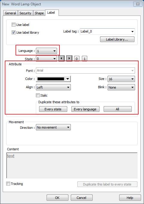
8 13-8 Read address Attribute Change state by time The state displayed changes on a time basis. The frequency can be set. Click [Setting] to select the [PLC name], [Address], [Device type], [System tag], [Index register] of the word device that controls the [Word Lamp] object. Users can also set address in [General] tab while adding a new object. No. of states The number of states is utilized by the object. The state is numbered from 0, so the number of states minus 1 will be the state number. If the value within the word register is *No. of states+ defined in Attribute, the highest state will be displayed. If the number of states is set to 8, the valid states will be 0, 1, 2,, 7. In this case if the word value is 8 or higher, the system will display the state 7 shape. Hide picture/shape if no corresponding picture for current state If selected, when there are not enough pictures to represent all the states, hides the picture. Otherwise, displays the last state. Note In [Label] tab, Language 1 determines the relevant settings of the font. For Language 2~8, only the font size can be changed and other settings follow Language 1.
9 13-9

10 Set Bit Overview The Set Bit object provides two operation modes: manual or automatic. Manual mode can trigger a designated bit address to change the state between ON and OFF when the object is touched. In automatic mode, the bit is automatically activated when a pre-defined condition occurs; touching the button will not be effective Configuration Click [Object]» [Set Bit] icon on the toolbar to open a Set Bit object property dialog box. Set up the properties, press OK button, and a new Set Bit object will be created. General Tab Setting Write address Description Click [Setting] to select the [PLC name], [Address], [Device type], [System tag], [Index register] of the bit device that controls the Set Bit object. Users can also set address in [General] tab while adding a new object. Write after button is released
11 13-11 If this function is selected, the action is delayed till button is released; otherwise, the action is executed once the button is pressed. This function does not work with momentary buttons. Mode / Offset Set style Description Set ON Set ON the designated bit of the device. Set OFF Set OFF the designated bit of the device. Toggle Alternates the bit state each time pressed. Momentary Holds the bit ON only while button is pressed. Periodical toggle Set a designated bit ON and OFF at a set time interval. Time interval can be selected; the range is from 0.1 to 25.5 seconds. Set ON when window opens Set ON the bit within the window when the window opens. Set OFF when window opens Set OFF the bit within the window when the window opens. Set ON when window closes Set ON the bit within the window when the window closes. Set OFF when window closes Set OFF the bit within the window when the window closes. Set ON when backlight on (N/A for cmt-svr) Set the bit ON when the backlight is turned ON. Macro Trigger mode Note Set OFF when backlight on (N/A for cmt-svr) Set ON when backlight off (N/A for cmt-svr) Set OFF when backlight off (N/A for cmt-svr) Set the bit OFF when the backlight is turned ON. Set the bit ON when the backlight is turned OFF. Set the bit OFF when the backlight is turned OFF. Set Bit object can trigger the start of a Macro routine when the Macro has been created in advance. For more information, see 18 Macro References. If [Set style] is set to [Toggle], there is a further selection to make of whether the macro operates after Off to ON, ON to OFF transition, or at both of the changes of state. In [Label] tab, if select [ON=OFF (use state 0)] check box, both state 0 and 1 follow the settings of state 0.
12 13-12 Using address types other than PLB or PLW_Bit for Set Bit objects with [Periodic Toggle] attribute is not supported by cmt-svr.

13 Set Word Overview The Set Word object provides two operation modes: manual or automatic. Manual mode can change the value in a designated word address when the object is touched. In automatic mode, the word register is automatically activated when a pre-defined condition occurs; touching the button will not be effective Configuration Click [Object]» [Set Word] icon on the toolbar to open a Set Word object property dialog box. Set up the properties, press OK button, and a new Set Word object will be created. General Tab
14 13-14 Setting Write address Notification Attribute Description Click [Setting] to select the [PLC name], [Address], [Device type], [System tag], [Index register] of the word device that controls the Set Word object. Users can also set address in [General] tab while adding a new object. Write after button is released If this function is selected, the action is delayed till button is released; otherwise, the action is executed once the button is pressed. If this check box is selected, it will notify a designated bit address (setting ON or OFF). Before writing / After writing Set the state of the designated bit address before or after the manual operation. Set Style Select the button action from the drop down list, see Example 2. Dynamic limits Set the [Bottom limit] and [Upper limit] by a designated register, see Example 1. Example 1 Set the [Bottom limit] and [Upper limit] by a designated register. When Dynamic Address is LW-n, where n is an arbitrary number, the rule of setting Upper / Bottom limit is: Content 16-bit 32-bit Dynamic address LW-n LW-n Bottom limit LW-n LW-n Upper limit LW-n+1 LW-n+2 When Dynamic Address is LW-100, the rule of setting Upper / Bottom limit is: Example 2 The available button actions are: Write constant value Content 16-bit 32-bit Dynamic address LW-100 LW-100 Bottom limit LW-100 LW-100 Upper limit LW-101 LW-102 Preset a register with the value entered. Each time when the button is pressed, it writes the [Set value] to the designated register. Data format is as set by the [Write address]; it can be 16-bit BCD, 32-bit BCD, 32-bit float. As shown below, when the button is pressed, preset the register with 12.
![13-15 Increment value (JOG+) Increase value in register by a set amount in [Inc. value], each time when the button is pressed, up to the [Upper limit].](/docs-images/93/114502123/images/15-0.jpg "As shown below, each button press increases the value in the register by 1 until the value is 10. Decrement Value (JOG-) Decrease value in register by a set amount in [Dec.")
15 13-15 Increment value (JOG+) Increase value in register by a set amount in [Inc. value], each time when the button is pressed, up to the [Upper limit]. As shown below, each button press increases the value in the register by 1 until the value is 10. Decrement Value (JOG-) Decrease value in register by a set amount in [Dec. value], each time when the button is pressed, down to the [Bottom limit]. As shown below, each button press decreases the value in the register by 1 until the value is 0. Press and hold increment (JOG++) When the button is held longer than a set time in [JOG delay], it will increase the value in a register by a set amount :[Inc. value] at a set rate :[JOG speed], to the [Upper limit]. As shown below, when the button is pressed, it increases the value in the designated register by 1. When the button is held longer than 1 second, it increases the value in register by 1 every 0.5 second, till the value is 10. Press and hold increment (JOG--) When the button is held longer than a set time in [JOG delay], it will decrease the value in a register by a set amount: [Dec. value] at a set rate: [JOG speed], to the [Bottom limit]. As shown below, when the button is pressed, it decreases the value in the designated register by 1. When the button is held longer than 1 second, it decreases the value in register by 1 every 0.5 second, till the value is 0.
16 13-16 Periodic JOG++ This automatic function increases the value in the register by a set amount: [Inc. value], at a set rate: [Time interval], to the [Upper limit]. As shown below, the system will automatically increase the value in the register by 1 every 0.5 second, till the value is 10. Then the value returns to 0 and add 1 every 0.5 second again. Automatic JOG++ This automatic function increases the value in the register by a set amount: [Inc. value], at a set rate: [Time interval], to the [Upper limit].then holds this value. As shown below, the system will automatically increase the value in the register by 1 every 0.5 second, till the value is 10, and then stop. Automatic JOG-- This automatic function decreases the value in the register by a set amount: [Dec. value], at a set rate: [Time interval], to the [Bottom limit].then holds this value. As shown below, the system will automatically increase the value in the register by 1 every 0.5 second, till the value is 10, and then stop.
17 13-17 Periodic bounce Increases the word address value to the [Upper limit] by a [Inc. value] at a set rate in [Time interval], then decreases to the [Bottom limit] by the same value at the same rate. As shown below, the system will increase the value in the designated register by 1 every 0.5 second, till the value is 10, and then decrease the value by 1 every 0.5 second till the value is 0 whenever the screen is active. Periodic step up Step up to the [High limit] by [Inc. value] at a set rate in [Time interval], then reset immediately to the [Low limit]. The action repeats whenever the screen is active. As shown below, the system will increase the value in the designated register by 1 every 0.5 second, till the value is 10, and then reset to 0 and increase again, and the action repeats. Periodic step down Step down to the [Low limit] by [Dec. value] at a set rate in [Time interval], then reset immediately to the [High limit]. The action repeats whenever the screen is active. As shown below, the system will decrease the value in the designated register by 1 every 0.5 second, till the value is 0, and then reset to 10 and decrease again, and the action repeats.
![13-18 Set when window opens / Set when window closes Automatic function occurs whenever the screen is active. The value entered in [Set value] is set into the word address when the action occurs.](/docs-images/93/114502123/images/18-0.jpg "If [Set value] is set to 5, when the window opens / closes, the system enters 5 into the designated register.")
18 13-18 Set when window opens / Set when window closes Automatic function occurs whenever the screen is active. The value entered in [Set value] is set into the word address when the action occurs. If [Set value] is set to 5, when the window opens / closes, the system enters 5 into the designated register. Set when backlight on / Set when backlight off (Not supported on cmt-svr) Automatic function occurs whenever the backlight is active. The value entered in [Set value] is set into the word address when the action occurs. If [Set value] is set to 5, when the backlight turns ON / OFF, the system sets 5 into the designated register. Cyclic JOG+ Each time when the button is pressed, increases the word address value to the [Upper limit] by [Inc. value] then reset to the [Bottom limit]. As shown below, each time when pressing the button, the system will increase the value in the designated register by 1, till the value is 10, and then reset to 0 and increase again by pressing the button. Cyclic JOG- Each time when the button is pressed, decrease the word address value to the [Bottom limit] by [Dec. value] then reset to the [Upper limit]. As shown below, each time when pressing the button, the system will decrease the value in the designated register by 1, till the value is 0, and then reset to 10 and decrease again by pressing the button. Cyclic JOG++ When the button is held longer than a set time in [JOG delay], it increases the value in a register by a set amount in [Inc. value] at a set rate in [JOG speed], to the [Upper limit], then reset to the [Bottom limit]. As shown below, when the button is held longer than 0.5 second, increase the value in the designated register by 1 every 0.1 second, till the value is 10, and then

![[Dec. value] at a set rate in [JOG speed], to the [Bottom limit], then reset to the [Upper limit].](/docs-images/93/114502123/images/19-1.jpg "As shown below, when the button is held longer than 0.5 second, decrease the value in the designated register by 1 every 0.")
19 13-19 reset to 0 and increase again by holding the button. Cyclic JOG- - When the button is held longer than a set time in [JOG delay], decrease the value in a register by a set amount in [Dec. value] at a set rate in [JOG speed], to the [Bottom limit], then reset to the [Upper limit]. As shown below, when the button is held longer than 0.5 second, decrease the value in the designated register by 1 every 0.1 second, till the value is 0, and then reset to 10 and decrease again by holding the button. Security Tab
20 13-20 Setting Interlock Description Use interlock function When this option is enabled and [Word] is selected, whether the object is operable depends on the condition of a word address specified in [Trigger if value is:]. In the settings above, the object is operable only when the value in LW-1 is greater than 1. Hide when disabled The object is hidden when the specified condition does not occur in the specified word address. Grayed label when disabled The label of the object turns gray when the specified condition does not occur in the specified word address. Trigger if value is: This setting is for specifying a trigger condition. The available options are: >, <, ==, <>, >=, and <=. A tolerance value can be set for conditions == and <>. For example: When the value is the specified word address is greater than or equal to 11, or smaller than or equal to 9, the object will be hidden and is not operable. Note Using address types other than PLW for Set Word objects with automatic attributes such as [Periodic set up], [Periodic set down], [Automatic JOG++], [Automatic JOG--], and [Periodic JOG++] etc, is not supported by cmt-svr.

![Function Keys with [Screen hardcopy] or [Import user data/use [USB Security Key]] selected do not work remotely on cmt Viewer. 13.5.2.](/docs-images/93/114502123/images/21-1.jpg "Configuration Click [Object]» [Function Key] icon on the toolbar to open a Function Key object property dialog box.")
21 Function Key Overview The Function Key object can be used for several tasks, such as switching between windows, keypad design, Macro execution, screen hardcopy, and setting USB security key. Function Keys with [Screen hardcopy] or [Import user data/use [USB Security Key]] selected do not work remotely on cmt Viewer Configuration Click [Object]» [Function Key] icon on the toolbar to open a Function Key object property dialog box. Set up the properties, press OK button, and a new Function Key object will be created. General Tab cmt Series emt, ie, XE, mtv Series

22 13-22 Setting Activate after button is released Change window Description If this function is selected, the action is delayed till button is released; otherwise, the action is executed once the button is pressed. Change full-screen window: Change to another base window. Change common window: Change common window. Display popup window: A pop-up window displays in the base window. If [Close this popup window when parent window is closed] check box is selected, the pop up window will be closed when change the base window to another window. Otherwise, a function key in the pop up window is needed to close it. (cmt Series) Animation Setting: cmt Series allows using transition effects for opening popup windows using Function Keys. The settings can be opened by clicking [Animation Setting]. The effects are shown below. Different effects may be used for Start (window appears) and End (window disappears). Effect Name Transition Fade Fly Float
23 13-23 Wipe Split Circle Clock Zoom Turn Push Keboard Input [Duration] specifies how many milliseconds (ms) a transition effect takes to complete. [Direction] The direction of the transition. Return to previous window: If this is selected, the Function Key will change from the current screen to the previous one displayed. For example, when window no. 10 is changed to window no. 20, press the function key to return to window no. 10. This function is only available for base window. Close window: Close any active pop-up windows, message windows included. Configures the button as a keypad key, and the character it enters, via [Numeric] or [ASCII] objects. Enter: Same as the keyboard s Enter function. Backspace: Same as the keyboard s Backspace function. Clear: Clear the value in the word register. Esc: Same as the [Close window] function; it is used to close the keyboard window.
24 13-24 Execute Macro Delete: Same as the keyboard s Delete function, deletes the number or character on the right side of the text cursor. Left: Same as the keyboard s key moves the text cursor to the left side of the previous number or character. Right: Same as the keyboard s key moves the text cursor to the left side of the next number or character. Inc: Increment by 1. Dec: Decrement by 1. ASCII/UNICODE: Specify the character to be entered by this key. Select this check box to execute one of the Macros from the drop down list that has already been configured by users. For more information, see 18 Macro References. Window title bar Function Key defined can be used to move a pop-up window which has no [window title bar] to a preferred position on screen. Select the pop-up window and then click on a preferred position, the window will be moved. Hard copy screen to USB disk, SD card or printer Print the current window. Before using this function, choose a printer model in [System Parameter Settings]» [Model]» [Printer]. If a monochrome printer is used, selecting [grayscale] can provide a better print result, but the text may not be clearly printed. To improve text printing, avoid using [grayscale]. Acknowledge all events Acknowledge all events once by pressing the Function Key.
![13-25 (alarms) (cmt Series) Import user data / Use [USB Security Key] A Function Key can be used to import the e-mail contacts or user accounts set, also, to log in using USB Security Key.](/docs-images/93/114502123/images/25-0.jpg "Notification Data Position Select the external device to store data from [SD card] or [USB disk].")
25 13-25 (alarms) (cmt Series) Import user data / Use [USB Security Key] A Function Key can be used to import the contacts or user accounts set, also, to log in using USB Security Key. Notification Data Position Select the external device to store data from [SD card] or [USB disk]. Account import mode If [Overwrite] is selected, the existing accounts will be overwritten with new accounts in the external device after importing. If [Append] is selected, HMI will append more accounts while the old accounts still exist. Delete file after importing user accounts If select this check box, the system will delete the account data saved in the external device after importing, this can prevent the account data from leaking out. If this selection is enabled, it will notify a designated bit address to set ON or OFF, each time the button is pressed. Note [Overwrite] is the only option when importing the contacts. This means that all existing contacts will be removed first, and then the new contacts are added. For more information, see 6 Window Operations, 12 Keypad Design and Usage, 36 Administrator Tools.

26 Toggle Switch Overview Toggle Switch object is a combination of Bit Lamp object and Set Bit object. The appearance of the object is controlled by the ON / OFF state of the read bit address. As well, pressing the button sets the value in the bit address according to the settings Configuration Click [Object]» [Toggle Switch] icon on the toolbar to open a Toggle Switch object property dialog. Set up the properties, press OK button, and a new Toggle Switch object will be created. General Tab
27 13-27 Setting Comment Read/Write use different addresses Read address Write address Description User can describe the information of the object. Bit Lamp / Toggle Switch Switch between Bit Lamp and Toggle Switch features. Different addresses can be used to read data and write data. Click [Setting] to select the [PLC name], [Address], [Device type], [System tag], [Index register] of the bit device that controls the [Toggle Switch] object. Users can also set address in [General] tab while adding a new object. Invert signal Reverses the display of ON / OFF states. For example, if [Invert signal] check box is selected, when the designated bit is OFF, the object displays ON state. When [Read/Write use different addresses] option is not selected, the title of this group box will be Read/Write address. Click [Setting] to select the [PLC name], [Address], [Device type], [System tag], [Index register] of the bit device that controls the [Toggle Switch] object. Users can also set address in [General] tab while adding a new object. The address can be the same or different from [Read address]. Write after button is released If this function is selected, the action is delayed till button is released, otherwise, the action is executed once the button is pressed. This function does not work with momentary buttons. Attribute Set style Description Set ON Set ON the designated bit of the device. Set OFF Set OFF the designated bit of the device. Toggle Alternates the bit state each time pressed. Momentary Holds the bit ON only while button is Macro pressed. Toggle Switch object can trigger the start of a Macro routine when the Macro has been created in advance. For more information, see 18 Macro References.

28 Multi-State Switch Overview Multi-state Switch object is a combination of Word Lamp object and Set Word object. The appearance of the object is controlled by the value of the read word address. As well, pressing the button sets the value in the word address according to the settings Configuration Click [Object]» [Multi-State Switch] icon on the toolbar to open a Multi-State Switch object property dialog box. Set up the properties, press OK button, and a new Multi-State Switch object will be created. General Tab cmt Series emt, ie, XE, mtv Series
29 13-29 Setting Comment Model / Offset Read/Write use different addresses Read address Write address Attribute Description User can describe the information of the object. Word Lamp / Multi-State Switch Switch between Word Lamp and Multi-State Switch features. Different modes can be selected: [Value], [LSB]. For more information, see 13.2 Word Lamp. Different addresses can be used to read data and write data. Click [Setting] to select the [PLC name], [Address], [Device type], [System tag], [Index register] of the word device that controls the Multi-state Switch object. Users can also set address in [General] tab while adding a new object. When [Read/Write use different addresses] option is not selected, the title of this group box will be Read/Write address. Click [Setting] to select the [PLC name], [Address], [Device type], [System tag], [Index register] of the word device that controls the Multi-state Switch object. Users can also set address in [General] tab while adding a new object. Write after button is released If this function is selected, the action is delayed till button is released; otherwise, the action is executed once the button is pressed. Switch style Select the object s operation mode, see Example 1. User-defined mapping The value placed in the write register of each selection, the action taken when an illegal value is entered, and error notification to a designated bit address can be set.

30 13-30 Send notification after writing successfully Error handling (cmt Series) Remain current state If an illegal value is entered, Multi-state Switch will remain at the current state. Jump to error state If an illegal value is entered, Multi-state Switch will jump to the error state. Error notification If an illegal value is entered, automatically set the value placed in the designated register. After the system successfully writes data to PLC, the designated bit address will be set On/Off. The action taken when an illegal value is entered or notify a designated bit address. This is similar to [User-defined mapping]; the difference is the value corresponding to each state need not to be preset. Example 1 JOG+ Increase the value of a designated register by 1 each time when pressing the button, till the value equals to [No. of states]. A cyclic action can be enabled. As shown below, each time when pressing the button, the state number will add 1 start from state 0, till state 4 ([no. of state]-1), and returns to 0 and step up again.

31 13-31 JOG- Decrease the value of the designated register by 1 each time when pressing the button, till the value equals to 0. A cyclic action can be enabled. As shown below, each time when pressing the button, the state number will minus 1 start from state 4 ([no. of state]-1), till state 0, and returns to state 4 and step down again.
32 Slider Overview Slider object is used to change the value in a designated word register address by moving the slide on the screen Configuration Click [Object]» [Slider] icon on the toolbar to open a Slider object property dialog box. Set up the properties, press OK button, and a new Slider object will be created. General Tab cmt
 Resolution Sets the value change in the word register for each step of the Slider.")

33 13-33 emt, ie, XE, mtv Setting Attribute Description Direction Select the direction of the slider. (Right, Up, Left, Down) Resolution Sets the value change in the word register for each step of the Slider. For example, if set to 10, the register value changes by 10 points for each increment or decrement on the Slider. Constant Sets the range of the Slider. For example, If set [Low limit] to 5, and [High limit] to 100, the Slider will enter values between 5 and 100. Address Set the [Low/High limit] by a designated register, see Example 1. Coarse increment Apart from moving the roller to change the value as in [Resolution],
34 13-34 Write address Notification Watch address if this option is selected, the word value will increase / decrease by the [Increment] value each time the object is touched. Click [Setting] to select the [PLC name], [Address], [Device type], [System tag], [Index register] of the word device that controls the Slider object. Users can also set address in [General] tab while adding a new object. If enabled, the state of a designated bit address will be set to ON or OFF before or after writing. Click [Setting] to select the [PLC name], [Address], [Device type], [System tag], [Index register] of the bit device that controls the notification settings. Users can also set address in [General] tab while adding a new object. [Before writing] / [After writing] Change the state of a designated bit register before, or after the slider is slid. When moving the roller, the new value written to the word register address can be displayed in real time. Example 1 Set the low or high limit by a designated register. When write address is LW-n, where n is an arbitrary number, the rule of setting limits is: Content 16-bit 32-bit Address LW-n LW-n Low limit LW-n LW-n High limit LW-n+1 LW-n+2 When address is LW-100, the rule of setting limits is: Content 16-bit 32-bit Address LW-100 LW-100 Low limit LW-100 LW-100 High limit LW-101 LW-102 Outline Tab cmt Seires
 Description Select slider button type, by default, a picture")


35 13-35 emt, ie, XE, mtv Seires Setting Slider button type (cmt) Slider button type (emt, ie, XE, mtv) Description Select slider button type, by default, a picture selected from the Picture Library can be the slider button. Four default styles are offered, and the width and color of the Frame, Background, Slot can be set Combo Setting cmt Series HMI support combo setting for Slider, which allows setting of multiple related objects at a time. Slider can be set with Background and Dynamic Scale.
36 13-36 Background Setting Margin Color/Style Description Specify the space between the background edge and the objects. Customize Select a suitable background pattern and color. Picture Use the default picture or choose a picture from Picture Library.

37 13-37 Dynamic Scale Setting Style Alignment Tick Mark Scale Label Description The scale style will follow the Slider. The position of the scale bar along the Slider. Configure the number of tick marks for main and sub scales, and the color of tick marks. Configure the font, font color, font size and other attributes of scale label. In Slider settings if [Address] is selected for Low/High limit, then Scale Label s [Dynamic limits] will be set automatically. In Slider settings if [Left] is selected for Direction, then Scale Label s [Reverse (Left/Right)] will be set automatically.
38 13-38

39 Numeric Overview Numeric object can be used to input or display the value of a designated word register Configuration Click [Object]» [Numeric] icon on the toolbar to open a Numeric object property dialog box. Set up the properties, press OK button, and a new Numeric object will be created. General Tab Setting Allow input Read / Write use different address Description If selected, the input features and relevant settings are enabled. Different addresses can be used to read data and write data.
![13-40 Read address Write address Notification Notification on invalid input Click [Setting] to select the [PLC name], [Address], [Device type], [System tag], [Index register] of the word device that](/docs-images/93/114502123/images/40-0.jpg "displays the value. Users can also select a tag defined in Address Tag Library.")
![When [Read/Write use different addresses] option is not selected, the title of this group box will be Read/Write address.](/docs-images/93/114502123/images/40-1.jpg "Select the [PLC name], [Device type], [Address] of the word device that system writes to. If this check box is selected, it will notify a designated bit address (setting ON or OFF).")
40 13-40 Read address Write address Notification Notification on invalid input Click [Setting] to select the [PLC name], [Address], [Device type], [System tag], [Index register] of the word device that displays the value. Users can also select a tag defined in Address Tag Library. When [Read/Write use different addresses] option is not selected, the title of this group box will be Read/Write address. Select the [PLC name], [Device type], [Address] of the word device that system writes to. If this check box is selected, it will notify a designated bit address (setting ON or OFF). Before writing / After writing Set the state of the designated bit address before or after the manual operation. If an illegal value is entered, automatically set the state of a designated register. Data Entry Tab cmt emt, ie, XE, mtv Series Setting Mode Description Touch Used when data entry is initiated by touching the screen object.
41 13-41 Allow input bit address Input order Keyboard Bit control Used when data entry is enabled by turning ON a designated bit, and entry ends when the bit goes OFF. Specify a bit address that enables or ends data entry. The order of data entry is specified in [Input order] and an external USB keyboard is needed for data entry. For cmt-svr, use ipad s keyboard. Perform continuous input by setting [Input order] and [Group]. The criterion of searching the next input object: The range of [Input order]: 1 ~ 511, range of [Group]: 1 ~ 15. If [Group] is not selected, its input order is 0. The system only searches for the objects within the same Group. The lower number of order is entered before the higher number of order. For multiple objects within the same group and with the same input order, the object placed in the lower layer is entered first. Use a popup keypad If selected: A pre-designed pop-up keypad can be chosen by selecting a check box, and selecting the relative position on the HMI screen. When data entry is enabled, the pop-up keypad displays in the selected position, and closed when data entry ends. If not selected: When data entry is enabled, the pop-up keypad is not displayed. Users may: Create a custom design on the same screen window. Use a USB keyboard. System keypad cmt Series model has its own system keypad, select this checkbox to use the system keypad, or select [Custom keypad] to set up a customized keypad. Animation Setting When using a cmt Series model with [Custom keypad] selected, the transition effect of the keypad window can be selected. See Chapter 13.5 Function Key in this manual for the list of effects. Hide title bar Use a keypad without the title bar.
![13-42 Popup position When using a cmt Series model with [Custom keypad] selected, the position where the keypad pops up can be selected.](/docs-images/93/114502123/images/42-0.jpg "The position can either be relative to HMI screen or relative to object.")


42 13-42 Popup position When using a cmt Series model with [Custom keypad] selected, the position where the keypad pops up can be selected. The position can either be relative to HMI screen or relative to object. Relative to HMI screen Relative to object Other options (For cmt Series) Restart the keypad if input value is out of range When entering data, if the value entered is not within the valid range, the system will automatically restart the keypad. Display lower and upper limits If selected, when entering a value, the range is displayed near the object. Display previous value If selected, when entering a value, the value before update is displayed near the object. To create a keyboard in current window, see 12 Keypad Design and Usage. Example 1 This example demonstrates how to use [Input Order] and [Group] to perform continuous input in several Numeric objects. After entering data in one object, entry will be passed to the next input order object which is in the same group. 1. Create three Numeric objects, and set [Input order] to 1, 2, and 3 respectively. Include the three objects in [Group 1] as shown in the following figure. LW-0

43 13-43 LW-1 LW-2 Group1 Order1 Order2 Order3 2. When finish entering data in the last object, to end data entry of all objects, please select [Stop sequential input function after input] check box.

44 13-44 Numeric Format Tab Setting Display Number of digits Display format Description Data Format Set the data format of a designated word register. The selections include: BCD, HEX, Binary, Unsigned, Signed, Float. 16-bit uses 1 word where 32-bit uses two words. Mask If selected, any values entered will be hidden by displaying them as ****. Left of decimal Pt. The number of digits before the decimal point. Right of decimal Pt. The number of digits after the decimal point. Each * sign represents each digit that will be displayed in the Numeric object. Apart from * signs, extra texts can be entered in
![13-45 the [Format] field, for example: kg. The available alignment options are: [Left], [Center], [Right], [Leading zero].](/docs-images/93/114502123/images/45-0.jpg "The numeric value represented by * sign will be displayed from the highest digit to the lowest in the Numeric object.")
45 13-45 the [Format] field, for example: kg. The available alignment options are: [Left], [Center], [Right], [Leading zero]. The numeric value represented by * sign will be displayed from the highest digit to the lowest in the Numeric object. Truncated digits Specify the number of digits to be truncated, from the lowest digit to the highest. The number of * signs = [Left of decimal Pt.]-[Truncated digits] Please see the following examples: Scaling When leading zero is not used, the text enclosed in two * signs will not show, for example: [Left of decimal Pt.] = 5, [Truncated digits] = 0, and Display Format is Total=**kg***g If the data read is 255, the result would be: "Total=255g" If the data read is 1000, the result would be: "Total=1kg000g" Interpolation If this check box is selected, [Engineering low] and [Engineering high] boxes appear. Values entered in these boxes correspond to the display range required. The setting also requires [Input low] and [Input high] in the limits section. See Example 2. Test: Preview the result of Interpolation. See Example 2. Dynamic scales: Set the [Engineering low] and [Engineering high] by a designated register. See Example 4. Macro subroutine The value read from or written to the register can be computed by
46 13-46 Limits Use alarm color macro subroutines selected in [Read conversion] and [Write conversion]. The macro subroutines should be defined in Macro Function Library. To use this feature, see The rule of using Macro subroutine. This section allows users to apply display limits to the values held in the input register. The color when the register value is outside limits can be set. Direct Sets the limits by entering values in [Input low] and [Input high]. If the value entered is outside the limits, the value in the register cannot be changed. Dynamic limits Set the limits by a designated register, see Example 5. Low limit When the value in the register is outside the [Low limit], display digits by the color set. High limit When the value in the register is outside the [High limit], display digits by the color set. Blink When the value in the register is outside either limit, the digits flash The rule of using Macro Subroutine There must be a return value and exactly one parameter. Examples: sub char test (short a) // (Correct) sub test (char a) // (Incorrect, no return value.) sub char test (char a, char b) // (Incorrect, two parameters.) Use the Macro data type that corresponds to the object s data format. The mapping is as follows: Macro Data Type Numeric Object Data Format short 16-bit Signed Int 32-bit Signed unsigned short 16-bit BCD, 16-bit HEX, 16-bit Binary, 16-bit Unsigned unsigned int 32-bit BCD, 32-bit HEX, 32-bit Binary, 32-bit Unsigned float 32-bit Float
47 13-47 For example, if the data format of the numeric object is 16-bit Unsigned, only the corresponding Macro data type: unsigned short, is available. Examples: sub char test(unsigned short a) // (Correct) sub char test(char a) // (Incorrect) Supports only the local HMI address. Examples: GetData(var, "Local HMI", LB, 0, 1) // (Correct) GetData(var, "MODBUS RTU", 0x, 0, 1) // (Incorrect) The following system defined functions are unable to be invoked: ASYNC_TRIG_MACRO, SYNC_TRIG_MACRO, DELAY, FindDataSamplingDate, FindDataSamplingIndex, FindEventLogDate, FindEventLogIndex, INPORT, INPORT2, OUTPORT, PURGE, TRACE The following statements are not supported: For-Next, While-Wend Example 2 If [Interpolation] is selected, the scaling equation is as the following: If A indicates the original data and B indicates the displayed data: B = [Engineering low] + (A - [PLC low]) Ratio where, Ratio = ([Engineering high] - [Engineering low]) / ([PLC high] - [PLC low]) As shown below, the original data is 15, after conversion, 40 will be displayed. Click [Test] button to preview the result of Interpolation. Enter a value in [PLC] field as shown in the following figure, for example, enter value 15, and the result, which is 40, will be displayed.


48 13-48 Example 3 If the numeric format selected is not Float and decimal point is used, the decimal place of the converted result will not be adjusted automatically, please adjust [Engineering high] to correctly place the decimal point of the result gained in [Interpolation] mode. Please see the illustration below. 1. Create two Numeric objects, set [Right of decimal Pt.] to 1 and select [Interpolation] method for one of the objects as shown in the following figure. 2. Enter value 123, the object set to [Interpolation] displays instead of 24.6.
![13-49 3. To move the decimal point one place to the left, adjust [Engineering high] as shown in the following figure.](/docs-images/93/114502123/images/49-0.jpg "Example 4 If [Interpolation] is selected, set the [Engineering low] and [Engineering high] by a designated register.")
49 To move the decimal point one place to the left, adjust [Engineering high] as shown in the following figure. Example 4 If [Interpolation] is selected, set the [Engineering low] and [Engineering high] by a designated register. When Dynamic Address is LW-n, where n is an arbitrary number, the rule of setting [Engineering low] and [Engineering high] is: Content 16-bit 32-bit Dynamic address LW-n LW-n Engineering low LW-n LW-n Engineering high LW-n+1 LW-n+2 When address is LW-100, the rule of setting limits is: Content 16-bit 32-bit Dynamic address LW-100 LW-100 Engineering low LW-100 LW-100 Engineering high LW-101 LW-102 Example 5 Set the limits by a designated register. When [Address] is LW-n, where n is an arbitrary number, the rule of setting limits is: Content 16-bit 32-bit Address LW-n LW-n Low limit LW-n LW-n High limit LW-n+1 LW-n+2

![The following two macros are used, one for [Read conversion] and one for [Write conversion]. 1.](/docs-images/93/114502123/images/50-1.jpg "Create two Numeric objects: NE_0 and NE_1 and use the same control address. Select [Macro subroutine] for NE_1. 2.")
50 13-50 When address is LW-100, the rule of setting limits is: Content 16-bit 32-bit Address LW-100 LW-100 Low limit LW-100 LW-100 High limit LW-101 LW-102 Example 6 The following demonstrates how to use [Macro subroutine] for scaling when configuring Numeric object. The following two macros are used, one for [Read conversion] and one for [Write conversion]. 1. Create two Numeric objects: NE_0 and NE_1 and use the same control address. Select [Macro subroutine] for NE_1. 2. Enter 0 in NE_0 then NE_1 will execute [Read conversion]. The value gained will be 10.
![13-51 3. Enter 80 in NE_1, [Write conversion] is executed and the value gained will be 70. NE_0 displays 70.](/docs-images/93/114502123/images/51-0.jpg "Note If executing [Read conversion] and [Write conversion] by the same numeric object, the value entered in this object is computed by the Macro subroutine of [Write conversion] first, and then the")
51 Enter 80 in NE_1, [Write conversion] is executed and the value gained will be 70. NE_0 displays 70. Note If executing [Read conversion] and [Write conversion] by the same numeric object, the value entered in this object is computed by the Macro subroutine of [Write conversion] first, and then the result is computed by the Macro subroutine of [Read conversion]. In Example 5, if the subroutine of [Write conversion] is set to b=a-20, then entering 80 in NE_1 will get 60 after [Write conversion] and then the object displays 70 after [Read conversion].
![13-52 Security Tab Setting Interlock Description Use interlock function When this option is enabled and [Word] is selected, whether the object is operable depends on the condition of a word address](/docs-images/93/114502123/images/52-0.jpg "specified in [Trigger if value is:]. In the settings above, the object is operable only when the value in LW-1 is greater than 1.")
52 13-52 Security Tab Setting Interlock Description Use interlock function When this option is enabled and [Word] is selected, whether the object is operable depends on the condition of a word address specified in [Trigger if value is:]. In the settings above, the object is operable only when the value in LW-1 is greater than 1. Hide when disabled The object is hidden when the specified condition does not occur in the specified word address. Grayed label when disabled The value in the object turns gray when the specified condition does not occur in the specified word address. Trigger if value is: This setting is for specifying a trigger condition. The available options are: >, <, ==, <>, >=, and <=. A tolerance value can be set for conditions == and <>. For example: When the value is the specified word address is greater than or equal to 11, or smaller than or equal to 9, the object will be hidden and is not operable.

53 13-53 Font Tab Setting Color Align Description When the value is within the limits, display digits using color set in this tab. Left: Align the number to the left. Center: Align the number to the center. Right: Align the number to the right. Leading zero: The number is preceded with leading zeros when the number of digits is less than that set. Size Set the font size.

54 ASCII Overview ASCII object can be used to input or display ASCII or UNICODE characters held in designated word registers Configuration Click [Object]» [ASCII] icon on the toolbar to open an ASCII object property dialog box. Set up the properties, press OK button, and a new ASCII object will be created. General Tab Setting Allow input Description If selected, the input features and relevant settings are enabled.
.")

55 13-55 Multi-line display Vertical alignment If selected, the ASCII object can display multi-lined text. If a line feed character LF (0xA) is used in the string, a newline will be created. When [Multi-line display] is enabled, the method to vertically align multiple lines of text can be selected. Mask If selected, any values entered will be masked by asterisks (*).. Use UNICODE Reverse high/low byte Select this check box to display data in UNICODE format. If not selected, the characters are displayed in ASCII format. This feature can be used with the [Function Key] object that uses [ASCII/UNICODE]. Normally an ASCII code is displayed in high byte, low byte order. Reverse selection makes the system display ASCII characters in low byte, high byte order. Read address Click [Setting] to select the [PLC name], [Address], [Device type], [System tag], [Index register] of the word device that displays characters. Users can select a defined address tag from Address Tag Library, or set address in [General] tab while adding a new object. No. of words Select the maximum number of words to be displayed. Note An UNICODE character uses 1 word, and an ASCII character uses 1 byte. Therefore 1 word can be used as 1 UNICODE character or 2 ASCII characters. (1 word equals to 2 bytes)

56 13-56 Font Tab Setting Attribute Description The font, size, color, and alignment can be set. Align Left: Align the text to the left. Center: Align the text to the center. Right: Align the text to the right.


57 Indirect Window Overview Indirect Window object opens or closes a pop-up window assigned by a designated word register. There are two ways to use Indirect Window object: The first is to use the profile of Indirect Window object, and let the pop-up window be resized and displayed in the defined profile; the second is to automatically resize the window according to the size of the pop-up window to be displayed. To close the pop-up window, assign 0 to the designated word register. The difference between Direct Window and Indirect Window is that Direct Window is controlled by a bit register, while Indirect Window is controlled by a word register Configuration Click [Object]» [Embed Window]» [Indirect Window] icon on the toolbar to open the object property dialog box. Set up the properties, press OK button, and a new Indirect Window object will be created. General Tab cmt Series emt, ie, XE, mtv Series Setting Read address Description Click [Setting] to select the [PLC name], [Address], [Device type], [System tag], [Index register] of the word device that controls the pop-up window. Users can also set address in [General] tab while
58 13-58 Attribute adding a new object. Style Set the display style of the pop-up window. There are two styles: No title bar The pop-up window has no title bar and cannot be dragged. With title bar The pop-up window has a title bar that can be dragged to move the window. Animation (cmt Series) Effect Different effects may be used for Start (window appears) and End (window disappears). Effect Name Transition Fade Fly Float Wipe Split
59 13-59 Circle Clock Zoom Turn Push Use window no. offset Auto. adjust window size Duration Specifies how many milliseconds (ms) a transition effect takes to complete. Direction The direction of the transition. Sets the offset of the window number for selecting the pop-up window. The window number of the pop-up window is calculated by the value in the word register added to the offset. For example, assume the value in the register is 20 and offset is 5, the pop-up window number will be 25. Automatically resizes the Indirect Window and align the pop-up window to the preset region. Alignment Sets a reference point of the pop-up window from one of the five positions on the screen. For example, if the lower-right region is selected, the lower-right corner of the pop-up window is aligned to the lower-right region of the Indirect Window. See Example 1. Example 1 Here is an example of using Indirect Window. The setting is shown in the following figure, set the address to LW-0 which assigns the window number. Create window no. 11 and 12 first. 1. Create an Indirect Window object, set address to LW-0, and select [Auto. adjust window size]. 2. Select the region where the window is to be displayed.


 windows in one base window.")
60 Enter value 11 in LW-0, the pop-up window displayed is window no Enter value 12 in LW-0, the pop-up window displayed is window no Enter value 0 in LW-0, the pop-up window is closed. To close the pop-up window, apart from entering 0 in the designated word register, another way is to place a Function Key object in the pop-up window, and set the key to [Close window]. Note At most 24 windows can be displayed simultaneously at run time. The system does not allow opening the same window with two Direct (or Indirect) windows in one base window. If the pop up window has monopoly property enabled, then when the window pops up, all background windows may not be operated until the monopolizing window has been closed.


61 Direct Window Overview Direct Window object opens or closes a pop-up window assigned by a designated bit register. When the state of the bit register changes, the pop-up window appears at the predefined location. The display area for the pop-up window is limited by the size of predefined location. Returning the state of the bit register closes the pop-up window. The difference between Direct Window and Indirect Window is that Direct Window is controlled by a bit register, while Indirect Window is controlled by a word register Configuration Click [Object]» [Embed Window]» [Direct Window] icon on the toolbar to open a Direct Window object property dialog box. Set up the properties, press OK button, and a new Direct Window object will be created. General Tab cmt Series emt, ie, XE, mtv Series Setting Read address Description Click [Setting] to select the [PLC name], [Address], [Device type], [System tag], [Index register] of the bit device that controls the pop-up window. Users can also set address in [General] tab while
62 13-62 Attribute adding a new object. Style Set the display style of the pop-up window. There are two styles: No title bar The pop-up window has no title bar and cannot be dragged. With title bar The pop-up window has a title bar that can be dragged to move the window. Animation Window no. Set the pop-up window number. Effect Different effects may be used for Start (window appears) and End (window disappears). Effect Name Transition Fade Fly Float Wipe
63 13-63 Split Circle Clock Zoom Turn Push Auto. adjust window size Duration Specifies how many milliseconds (ms) a transition effect takes to complete. Direction The direction of the transition. Automatically resizes the Direct Window and align the pop-up window to the preset region. Alignment Sets a reference point of the pop-up window from one of the five positions on the screen. For example, if the lower-right region is selected, the lower-right corner of the pop-up window is aligned to the lower-right region of the Direct Window. See Example 1. Example 1 Create window no. 11 which can be controlled by a Toggle Switch with address LB Create a Direct Window object and set read address to LB In this example, the reference point for alignment is set to the lower-right region.

64 When LB-0 s state is ON, window no. 11 will show. 4. When LB-0 s state is OFF, window no. 11 will be hidden.
65 13-65 Note A screen can simultaneously display up to 24 pop-up windows including System Message Window, Direct Window and Indirect Window. The system does not allow opening the same window with two Direct (or Indirect) Windows in one base window. If the pop up window has monopoly property enabled, then when the window pops up, all background windows may not be operated until the monopolizing window has been closed.

66 Moving Shape Overview Moving Shape object defines the states and moving distance of an object. The state and the location of the object depend on consecutive registers Configuration Click [Object]» [Animation]» [Moving Shape] icon on the toolbar to create a Moving Shape object. Set up the properties, press OK button, and a new Moving Shape object will be created. General Tab Setting Read address Description Click [Setting] to configure the [PLC name], [Device type], [Address], [System tag], or [Index register] of the word devices that control the display of object s state and moving distance. Users can also set the address in [General] tab while adding a new object.
67 13-67 Attribute Select the object s movement mode and range. See Illustration of Modes in the following part. Display ratio The size of shape in different states can be set individually as shown in the following figure. Limit address The object s moving range can be set by adjusting the data in the designated register, see Example 1. Example 1 Supposed that the object s moving range is limited by register LW-n, the addresses in the following table are used to limit the moving range. Data format 16-bit 32-bit [Min. X] address LW-n LW-n [Max. X] address LW-n+1 LW-n+2 [Min. Y] address LW-n+2 LW-n+4 [Mas. Y] address LW-n+3 LW-n Illustration of Modes Available modes are: (Assume Read Address is LW-n) X axis only The object is only allowed to move along the X-axis. The moving distance ranges from [Min. X] to [Max. X]. Data format 16-bit 32-bit Object state LW-n LW-n Moving distance on X-axis LW-n+1 LW-n+2 Y axis only The object is only allowed to move along the Y-axis. The moving distance ranges from [Min. Y] to [Max. Y].

68 13-68 Data format 16-bit 32-bit Object state LW-n LW-n Moving distance on Y-axis LW-n+1 LW-n+2 X & Y axis The object is allowed to move along the X-axis and Y-axis. The moving range in X and Y directions is defined by [Min. X], [Max. X] and [Min. Y], [Max. Y] respectively. Data format 16-bit 32-bit Object state LW-n LW-n Moving distance on X-axis LW-n+1 LW-n+2 Moving distance on Y-axis LW-n+2 LW-n+4 For example, if the object s read address is LW-100 and the data format is [16-bit Unsigned], LW-100 is used to control the object s state, LW-101 is used to control the object s moving distance on the X-axis, and LW-102 is used to control the object s moving distance on the Y-axis. The following figure shows that the object s read address is LW-100 and initial position is (100, 50). To move the object to the position (160,180) and change its state to State 2, assign 2 to LW-100, = 60 to LW-101, = 130 to [LW102].
69 13-69 X axis w/ scaling The object moves in X-axis only with scaling. Suppose that the value of the designated register is DATA, the system uses the following equation to calculate the moving distance on the X-axis. [Scaling high]-[scaling low] Displacement=(Data-[Input low]) [Input high]-[input low] Data format 16-bit 32-bit Object state LW-n LW-n Moving distance on X-axis LW-n+1 LW-n+2 Y axis w/ scaling The object is for Y axis movement with scale, and the equation to calculate the moving distance on the Y-axis is the same as the one in [X axis w/ scaling]. Data format 16-bit 32-bit Object state LW-n LW-n Moving distance on Y-axis LW-n+1 LW-n+2 X axis w/ reverse scaling This works in the way as [X axis w/ scaling], but the moving direction is in reverse. Y axis w/ reverse scaling This works in the way as [Y axis w/ scaling], but the moving direction is in reverse.
70 Animation Overview Animation object is defined by a pre-defined point set and states. Animation object will then move to a given point in a given state defined by designated registers. The object state and position depend on current value of two consecutive registers. The first register controls the state of the object and the second register controls the position along the predefined path Configuration Click [Object]» [Animation]» [Animation] icon on the toolbar. First, create the pre-defined path. Move the mouse to each moving position, and click the left button to define positions one by one. When it is done, right click on the screen, set up the properties, press OK button, and a new Animation object will be created. To change the object s attributes, double click on the object to open Animation Object s Properties dialog box.

71 13-71 General Tab Setting Attribute Description No. of states Configure the number of states for this object. Controlled by register Use the designated registers to control the object s state and position. See Example 1. Based upon time interval The object s state and position will change from time to time. [Time interval attributes] is used to set the time interval for states and positions. Position speed: The speed of movement. The unit is 0.1 second. Supposed that *Speed+ is set to 10, the object s position will change each second.
72 13-72 Image state change: Determines how state changes, either [Position dependent] or [Time-based]. If [Position dependent] is selected, the object state will change when position changes. If [Time-based] is selected, the object position will change based on [Position speed] and the object state will change based on [Image update time]. Backward cycle: Assumed the object has four positions: position 0, position 1, position 2, and position 3, and [Backward cycle] is not selected. When the object moves to the last position (position 3), the next position will be back to the initial position 0, and repeat. The moving path is shown as follows: position 0 position 1 position 2 position 3 position 0 position 1 position 2 If [Backward cycle] is selected, when the object moves to the last position (position 3), it will move backwards to position 2, position 1 and then the initial position 0, and start over again. The moving path is shown as follows. position 0 position 1 position 2 position 3 position 2 position 1 position 0 Example 1 The object s state and position are determined by the registers, and the addresses must be configured correctly, as in the following table: Data format 16-bit 32-bit Object state LW-n LW-n Object position LW-n+1 LW-n+2 For example, if the designated register is LW-100 and the data format is [16-bit Unsigned], then LW-100 represents object s state, LW-101 represents position. In the picture below, LW-100 = 2, LW-101 = 3, so the object s state is 2 and position is 3.

73 13-73 Profile Tab Setting Shape rectangle size Trajectory Description Set the size of the shape. Set the position of each point on the moving path. Note Since multiple pictures might be used by an [Animation] object, [Set to original dimension] will not return all pictures to the original size.

74 Bar Graph Overview Bar Graph object displays data as a bar graph for visualization Configuration Click [Object]» [Chart]» [Bar Graph] icon on the toolbar to open Bar Graph dialog box. Select properties, click OK button, a new Bar Graph object is created. General Tab cmt
![13-75 emt, ie, XE, mtv Setting Read address Description Click [Setting] to Select the [PLC name], [Device](/docs-images/93/114502123/images/75-0.jpg "type], [Address], [System tag], and [Index register] of the word devices that controls how the bar graph")
75 13-75 emt, ie, XE, mtv Setting Read address Description Click [Setting] to Select the [PLC name], [Device type], [Address], [System tag], and [Index register] of the word devices that controls how the bar graph displays.

76 13-76 Outline Tab cmt emt, ie, XE, mtv
![13-77 Setting Type Attribute Description Choose either [Bar] or [Circular]. Mode Choose either [Normal] or [Offset]. If [Offset] is selected, an original value [Origin] must be entered for reference.](/docs-images/93/114502123/images/77-1.jpg "Direction / Degree Bar: Determine the bar graph direction. Available options are [Up], [Down], [Right], and [Left]. Circular: Determine the circular bar graph direction.")
![Available options are [Clockwise] and [Counter clockwise]. If [Full circle] is selected, set the start degree. If [Full circle] is not selected, set the start and end degree.](/docs-images/93/114502123/images/77-2.jpg "Bar width ratio (%) The ratio of bar to object width. The figure below shows two ratios, 100% and 50%.")
77 13-77 Setting Type Attribute Description Choose either [Bar] or [Circular]. Mode Choose either [Normal] or [Offset]. If [Offset] is selected, an original value [Origin] must be entered for reference. Direction / Degree Bar: Determine the bar graph direction. Available options are [Up], [Down], [Right], and [Left]. Circular: Determine the circular bar graph direction. Available options are [Clockwise] and [Counter clockwise]. If [Full circle] is selected, set the start degree. If [Full circle] is not selected, set the start and end degree. Bar width ratio (%) The ratio of bar to object width. The figure below shows two ratios, 100% and 50%. Hole Radius (%) The ratio of the radius of the hole to the radius of the whole circular bar graph. The figure below shows two ratios, 0% and 50%. Color/Style Set the bar s frame and background color, bar style, and bar color. See the picture below.

![If the register value is larger than [High limit], the color of filled area will change to [High color].](/docs-images/93/114502123/images/78-1.jpg "If the register value is smaller than [Low limit], the color will change to [Low color].")
![When [Enable] is selected, the [Low limit] and [High limit] of [Alarm indicator] and the [Target Value] of [Target indicator] will use designated registers,](/docs-images/93/114502123/images/78-2.jpg "which is shown in their respective fields see Example 3.")
78 13-78 Range Tab Setting Zero / Span Target indicator Alarm indicators Dynamic taget/alarm /zero(span) Description The percentage of filling can be calculated by the formula, see Example 1. When the register value meets the condition, the color of filled area will change to the target color, see Example 2. If the register value is larger than [High limit], the color of filled area will change to [High color]. If the register value is smaller than [Low limit], the color will change to [Low color]. When [Enable] is selected, the [Low limit] and [High limit] of [Alarm indicator] and the [Target Value] of [Target indicator] will use designated registers, which is shown in their respective fields see Example 3. Example 1 The percentage of filling can be calculated by the following formula: Percentage of filling = Register value [Zero] [Span] [Zero] 100% Assume [Offset] is selected. If (Register value [Zero]) is greater than 0, the bar will fill up from
![13-79 [Origin]. If (Register value Zero) is less than 0, the bar will be drawn below [Origin]. For example, [Origin] is 5, [Span] is 10, and [Zero] is 0.](/docs-images/93/114502123/images/79-0.jpg "For different value in read address, it will display as below: If the value at read address is 4: If the value at read address is 8: Example 2 When the register value meets the following condition,")
![the color of filled area will change to the target color. [Target Value] - *Tolerance+ Register value *Target Value+ + *Tolerance] Assume [Target Value] is 5 and [Tolerance] is 1.](/docs-images/93/114502123/images/79-1.jpg "As shown below, if the register value is equal to or larger than 4 (=5-1) and equal to or less than 6 (=5+1), the filled area s color of the bar will change to the target color.")
79 13-79 [Origin]. If (Register value Zero) is less than 0, the bar will be drawn below [Origin]. For example, [Origin] is 5, [Span] is 10, and [Zero] is 0. For different value in read address, it will display as below: If the value at read address is 4: If the value at read address is 8: Example 2 When the register value meets the following condition, the color of filled area will change to the target color. [Target Value] - *Tolerance+ Register value *Target Value+ + *Tolerance] Assume [Target Value] is 5 and [Tolerance] is 1. As shown below, if the register value is equal to or larger than 4 (=5-1) and equal to or less than 6 (=5+1), the filled area s color of the bar will change to the target color. Example 3 If [Dynamic target/alarm] is enabled, [Low limit] and [High limit] of [Alarm indicator] are defined by designated registers as shown in the following table. Furthermore, if [Dynamic zero/span] is used, [Zero], [Span] and [Origin] will be defined by designated registers. Assume the address is LW-n, the limits are: Data format 16-bit 32-bit Alarm Low Limit LW-n LW-n

80 13-80 Alarm High Limit LW-n+1 LW-n+2 Target LW-n+2 LW-n+4 Zero LW-n+3 LW-n+6 Span LW-n+4 LW-n+8 Origin LW-n+5 LW-n Combo Setting cmt Series HMI support combo setting for Bar Graph, which allows setting of multiple related objects at a time. Bar Graph can be set with Background and Dynamic Scale.
81 13-81 Background Setting Margin Color/Style Description Specify the space between the background edge and the objects. Customize Select a suitable background pattern and color. Picture Use the default picture or choose a picture from Picture Library.
82 13-82 Dynamic Scale Setting Style Tick Mark Scale Label Description The scale style will follow the bar type. Configure the number of tick marks for main and sub scales. If the style is circular, the radius and tick mark length can be specified. Configure the font, font color, font size and other attributes of scale label.

83 Meter Display Overview Meter Display object displays the value of word register with a meter Configuration Click [Object]» [Chart]» [Meter Display] icon on the toolbar to open the Meter Display dialog box. Set the object s attributes and then click OK to create a new Meter Display object emt, ie, XE, mtv Series General Tab Setting Read address Description Click [Setting] to select the [PLC name], [Device type], [Address], [System tag], and [Index register] of the word devices that controls the Meter Display object.

84 13-84 Outline Tab Setting Degree Description Set the pointer to go around the meter clockwise or counterclockwise. Sets the object s start degree and end degree measured clockwise from the 12 o clock position. The angle range is 0 to 360 degrees. The following shows meters of different settings.
![13-85 [Start degree] =290 [End degree] = 70 [Start degree] = 120 [End](/docs-images/93/114502123/images/85-0.jpg "degree] = 240 [Start degree] = 40 [End degree] = 140 [Start degree] =")
![225 [End degree] = 315 Background Sets the object s background color](/docs-images/93/114502123/images/85-1.jpg "and profile color.")


85 13-85 [Start degree] =290 [End degree] = 70 [Start degree] = 120 [End degree] = 240 [Start degree] = 40 [End degree] = 140 [Start degree] = 225 [End degree] = 315 Background Sets the object s background color and profile color. Full circle When selected, the object will display the whole circle. Otherwise, the object will only display a partial circle in the defined degree range, as shown in the following figure. Tick marks Pointer Pin point Transparent When selected, the object will not display the background and profile color. Configures the number of tick mark and color. Configures pointer s style, length, width, and color. Configures the style, radius, and color of the pin point.

86 13-86 Limits Tab Setting Value Range limits Description Sets the object s display range. Meter Display object will use the value of [Zero] and [Span] and the value of register to calculate the pointer s position. See Example 1. Configures the values of [Low limit], [High limit], their corresponding display colors, and the width. Use user-defined radius Configures the radius to display range limits. For example, set to 80: Set to 30:

![For example, supposed that [Zero] is 0, [Span] is 100, when the value of register is 30, [Start degree] is 0, and [End degree] is 360, then the degree indicated by the pointer is: { (30 [Zero]) /](/docs-images/93/114502123/images/87-1.jpg "([Span] [Zero]) } * ([End degree] - [Start degree]) = {(30 0) / (100-0)} * (360 0) = 108 Pointer will be pointing at 108 degrees.")
87 13-87 Scale label Dynamic Limits The low limit and high limit are set by registers. See Example 2. Select the attribute of scale label on Meter Display. Example 1: Pointer position calculation Set object s display range. Meter Display object will use the value of *Zero+ and *Span+ and the value of register to calculate the pointer s position. For example, supposed that [Zero] is 0, [Span] is 100, when the value of register is 30, [Start degree] is 0, and [End degree] is 360, then the degree indicated by the pointer is: { (30 [Zero]) / ([Span] [Zero]) } * ([End degree] - [Start degree]) = {(30 0) / (100-0)} * (360 0) = 108 Pointer will be pointing at 108 degrees. Example 2: Dynamic Limits The low limit and high limit are set by the register. Suppose the address is LW-n, the following table shows the read address of low limit and high limit: Content 16-bit 32-bit Low limit LW-n LW-n High limit LW-n+1 LW-n+2 For instance, when address is LW-100, the rule of setting limits is: Content 16-bit 32-bit Low limit LW-100 LW-100 High limit LW-101 LW-102

![available: [Custom], [Style 1], and [Style 2].](/docs-images/93/114502123/images/88-1.jpg "Click on the text to configure the properties.")
88 cmt Series General Tab Setting Style Description Three options are available: [Custom], [Style 1], and [Style 2]. Click on the text to configure the properties. If [Custom] is selected, set the properties such as [Pointer], [Pin point], [Background picture], etc.
![13-89 Setting Click the button of [Style 1] or [Style 2] to set the style of meter. Outline The following is the outline of Style 1 when [Full circle], [Half circle], or [Quarter circle] is selected.](/docs-images/93/114502123/images/89-0.jpg "The following is the outline of Style 2 when [Full circle], [Half circle], or [Quarter circle] is selected.")

89 13-89 Setting Click the button of [Style 1] or [Style 2] to set the style of meter. Outline The following is the outline of Style 1 when [Full circle], [Half circle], or [Quarter circle] is selected. The following is the outline of Style 2 when [Full circle], [Half circle], or [Quarter circle] is selected. Angle Enable animation Value Read address Indicator Rotation Rotates the background picture clockwise according to the angles set. Color Sets the color of the background picture of meter. Sets the range to label the scale, 0 to 360 clockwise or counterclockwise from the twelve o clock position. Full circle If selected, the full circle is drawn according to the selected direction and the start angle. The limits are determined by the value set in [Minimum] and [Maximum] field under [Value]. If selected, the pointer slides to the designated position when the read value changes; if not selected, the pointer directly points to the designated position when the read value changes. Sets the lower and upper limits of the meter. Displays the value in meter according to the value in the designated word register. Sets the style of pointer and pin point. If [Custom] is selected, the direction of the pointer must points upward to correctly display.
90 13-90 Range limit Scale Sets the colors to indicate different ranges. Dynamic limits The low limit and high limit are decided by the register. See Example 2 above. Sets the number of main and sub scale, the color of tick marks and scale label.

91 Trend Display Overview Trend display objects draw curves of the data recorded by Data Sampling object Configuration Click [Data/History]» [Trend Display] icon on the toolbar to open a Trend Display object property dialog box. Set up the properties, press OK button, and a new Trend Display object will be created emt, ie, XE, mtv Series General Tab Button Description Go to the earliest sampling data. Go to the previous time interval. Click to stop auto-scrolling. When the new sampling data is generated, the display does not scroll, nor is the new data outside the display range displayed. Click to start auto-scrolling. The display scrolls as the new sampling data is generated. Go to the next time interval. Go to the latest sampling data.

92 13-92 Setting Data Sampling Object index Refresh data automatically No line connection between records if the next record is earlier Trend type Description Select a Data Sampling object as the source data. In history mode, when this option is selected, Trend Display will be automatically refreshed every 10 seconds. If this option is not selected, Trend Display can only be refreshed by changing window. When HMI time is adjusted to an earlier time, and data sampling keeps going on, selecting this option can prevent the system from drawing a line to connect the gap between current trend curve (earlier in time axis) and former trend curve (later in time axis). This can slow down refresh speed. Select the mode of data source, either [Real-time] or [History]. Real-time In this mode, the display object shows all sampled data since the HMI started. The maximum number of records that can be sampled is set in [Max.data records] (Real-time mode) of the Data Sampling object. When the sampling data exceed this setting, the earlier
![13-93 Pixel data will be deleted.to show older data, use [History] mode. [Hold control]: Suspends the update of Trend Display. However, It does not stop the sampling process of Data Sampling object.](/docs-images/93/114502123/images/93-0.jpg "History In this mode, the data comes from the history data files stored on HMI.. The history data files are sorted by dates and each is given an index.")
93 13-93 Pixel data will be deleted.to show older data, use [History] mode. [Hold control]: Suspends the update of Trend Display. However, It does not stop the sampling process of Data Sampling object. History In this mode, the data comes from the history data files stored on HMI.. The history data files are sorted by dates and each is given an index. The system uses [History control] to select the history data files that are created on different dates. The system sorts the history data of sampling data by date; the latest file is record 0 (typically the data sampled today), the second latest file is record 1, and so on. If the value of designated register in [History control] is n, the Trend Display object will display data record n. Here is an example to explain [History control]. If the designated register is LW-0, and the sampling data files available are pressure_ dtl, pressure_ dtl, pressure_ dtl, and pressure_ dtl, and it is 2006/12/3 today, based on the value of LW-0, the sampling data file which will be selected by [Trend Display] is shown as follows: Value of LW-0 Selected sampling history data 0 pressure_ dtl 1 pressure_ dtl 2 pressure_ dtl 3 pressure_ dtl If use with Option List object and select data source as [Dates of historical data], the history data will be sorted by date and displayed in Option List object, see Option List. [Distance] is used to set the distance between two sampling points, as shown in the following figure. Time [Distance] is used to set the X-axis in unit of time, as shown in the following figure.
![13-94 Dynamic distance between data samples/ Dynamic X axis time range Refresh data automatically Hold control Select [Time] for [X axis time range] and go to [Trend]» [Grid] and enable [Time scale].](/docs-images/93/114502123/images/94-0.jpg "Please refer to [Time scale] in the later section.")
94 13-94 Dynamic distance between data samples/ Dynamic X axis time range Refresh data automatically Hold control Select [Time] for [X axis time range] and go to [Trend]» [Grid] and enable [Time scale]. Please refer to [Time scale] in the later section. Designate a 32-bit word register for adjusting the distance between two sampling points (select Pixel), or the time unit represented by X-axis (select Time). If no value is entered, the default value will be used. If selected, every time when opening the window on which the Trend Display object in history mode is placed, the display is automatically refreshed once per second. Please note that: The refresh status can be observed from the control button of Trend Display object. Showing button: The automatic refresh feature is enabled. Showing button: The automatic refresh feature is disabled. When scrolling to the previous data, the automatic refresh feature is disabled, the button is shown. If [Refresh data automatically] check box is selected, when change back to the window, the display is refreshed, ignoring the control buttons. For example, select [Refresh data automatically], and scroll to the previous data, the automatic refresh feature is disabled. In this case, changing to another window and then change back will still refresh the display. If [Refresh data automatically] check box is not selected when building the project, the feature can still be enabled by pressing button on HMI. In this case, the automatic refresh feature is disabled, that is, even when change back to the current window, the display will not be refreshed. When the register is set ON, suspend the update of Trend Display. It

95 13-95 Watch line does not stop the sampling process of Data Sampling object. This setting is available only in Real-time mode. Use the *Watch line+ function to display a watch line when user touches the Trend Display object. It will also export the sampling data at the position of watch line to the designated word device and use Numeric objects to display the results, as shown in the following figure. Time stamp output [Watch line] can also export sampling data with multiple channels. The system will consecutively write each channel to the specified address and the following addresses, in the same order as in [Data Sampling] object. The address assigned to [Watch line] is the start address, and sampling data for each channel will be exported to the word devices starting from start address. If the data format of each channel is different, the corresponding address of each channel is arranged from the first to the last. If the watch register is LW-300, watch function will export each channel s data to the following addresses: Register Channel Data format LW bit Unsigned (1 word) LW bit Unsigned (2 words) LW bit float (2 words) LW bit Signed (1 word) Time stamp output Suppose the address is set to LW-n, then: If enabled, the system will use the time of the first sampling data as time origin, and write the time stamp of the most recent sampled data (relative to time origin ) to [LW-n+2]. When clicking on the curve, the time stamp of the closest sampled point will be written to [LW-n]. Clear real-time data address (Data Sampling object) will clear the

96 13-96 time origin as well. Time stamp is recorded in seconds. Trend Tab Setting Transparent / Frame / Background Show scroll controls Description Select the color of frame and background. Enable or disable the scroll control as shown in the following figure. Grid Set the number of dividing lines and the line color. The number of divisions depends on the setting in General tab» [Distance between data samples] / [X axis time range]. X-axis interval The number of vertical grid lines. Select [Distance between data samples] in General tab:
![13-97 Time scale Select how many sampling point will be included between two vertical grid lines. Select [X axis time range] in General tab: Select the time range between two vertical grid lines.](/docs-images/93/114502123/images/97-0.jpg "X-axis division The number of vertical grid lines. Y-axis division The number of horizontal grid lines. Select [Time] / [Date] check box to display the time scale along the x axis.")
97 13-97 Time scale Select how many sampling point will be included between two vertical grid lines. Select [X axis time range] in General tab: Select the time range between two vertical grid lines. X-axis division The number of vertical grid lines. Y-axis division The number of horizontal grid lines. Select [Time] / [Date] check box to display the time scale along the x axis. Time / Date Font / Color / Size Select the font, font color, and font size of the time scale. The default font size is 8. Relative time mode When this mode is selected, the time of the earlist sampling data will be the start time from which to count a relative time. This mode works with time scale [SSSSSS] and under this mode, time scale [Date] cannot be used. The time of the latest sampling data will be marked on the top left corner of the object. This group box is used to set the time / date display format and font color.
98 13-98 Channel Tab Setting Y scale Description Set Y-axis to be Main Axis or Aux. Axis. See Y Scale Tab for more information. Channel Configure each sampling line s format and color. At most 64 channels could be configured. Dynamic limits Not selected: [Zero] and [Span] are used to set the low limit and high limit of sampling data. If the low limit is 50 and the high limit is 100 for one sampling line, [Zero] and [Span] must be set as [50] and [100], so that all the sampling data can be displayed in the trend display object. Selected The low limit and the high limit are read from the designated word devices, as shown below. When address is LW-n, the register s
99 13-99 Channel visibility control address: Data Format 16-bit 32-bit Low limit LW-n LW-n High Limit LW-n+1 LW-n+2 For example, if LW-100 is used here, the low limit and the high limit will be read from: Data Format 16-bit 32-bit Low limit LW-100 LW-100 High Limit LW-101 LW-102 A typical usage of this is to zoom in and zoom out of Trend Display. (Not available for cmt Series). See Example 1. If [Enable] is selected, the bits of the assigned word register will be used to show/hide each channel. The first bit controls the first channel, and the second bit controls the second channel, and so on. For example, suppose there are 5 channels and LW-0 is used, channels which will be shown given the states of the control bits are: Channel Control Bit State Displayed 1 LW_bit-000 OFF YES 2 LW_bit-001 ON NO 3 LW_bit-002 ON NO 4 LW_bit-003 OFF YES 5 LW_bit-004 OFF YES Note on using this feature: Each control bits are not reserved for the channel. If a particular channel is not displayed, the control bit is assigned to the next displayed channel. For example, if the third channel of the 5 channels is not displayed, only 4 channels will be displayed in Trend Display, and the used control bits will only be: LW_bit-000~003.

100 Y Scale Tab Setting Y scale Scale font Dynamic Y-scale visibility Dynamic main axis Description Show whether Y-axis is Main Axis or Aux. Axis. See Y Scale Tab in this manual. Y-axis will not be displayed when [none] is selected for Y scale in Data Sampling Object group box. Select the font, font color, and font size of the scale. To show or hide Y-scale. If the control address is LW-50, then the first axis is controlled by LW_Bit 5000, and the second axis is controlled by LW_Bit 5001, and so on. To change the main axis. If writing 1 into LW-80, the main axis will be Channel 1; if writing 2 into LW-80, the main axis will be Channel, and so on.


101 cmt Series General Tab The Trend Display on cmt Series combines Real-time mode and History mode. Drag left to scroll the Trend Display to view history data and drag right to view the latest sampling data. Pinch two fingers together to zoom out Trend Display or spread them apart to zoom in. Zoom In Zoom Out For more information about how sampling data is saved, see 8 Data Sampling.
![13-102 Setting Data Sampling Object index Millimeter Time Watch line Description Select a [Data Sampling] object](/docs-images/93/114502123/images/102-0.jpg "as the source data. Same as emt, ie, XE mtv Series.")
102 Setting Data Sampling Object index Millimeter Time Watch line Description Select a [Data Sampling] object as the source data. Same as emt, ie, XE mtv Series. Same as emt, ie, XE mtv Series. Same as emt, ie, XE mtv Series.

103 Trend Tab Setting Transparent / Frame / Background Grid Description Select the color of frame and background. Set the number of dividing lines and the line color. The number of divisions depends on the setting in General tab» [Distance between data samples] / [X axis time range]. X-axis interval The number of vertical grid lines. Select [Distance between data samples] in General tab: Select how many sampling point will be included between two vertical grid lines. Select [X axis time range] in General tab: Select the time range between two vertical grid lines. X-axis division
![13-104 Time scale Time / Date The number of vertical grid lines. Y-axis division The number of horizontal grid lines. Select [Time] / [Date] check box to display the time scale along the x axis.](/docs-images/93/114502123/images/104-0.jpg "The default font size is 8. The time of latest sampling data will be marked on the top left corner of the object. This group box is used to set the time / date display format and font color.")
104 Time scale Time / Date The number of vertical grid lines. Y-axis division The number of horizontal grid lines. Select [Time] / [Date] check box to display the time scale along the x axis. The default font size is 8. The time of latest sampling data will be marked on the top left corner of the object. This group box is used to set the time / date display format and font color. Channel Tab Setting Y scale Description Set Y-axis to be Main Axis or Aux. Axis. See Y Scale Tab for more information. Channel Configure each sampling line s format and color. At most 64 channels could be configured. Dynamic limits
105 Channel visibility control Not selected: [Zero] and [Span] are used to set the low limit and high limit of sampling data. If the low limit is 50 and the high limit is 100 for one sampling line, [Zero] and [Span] must be set as [50] and [100], so that all the sampling data can be displayed in the trend display object. Selected The low limit and the high limit are read from the designated word devices, as shown below. When address is LW-n, the register s address: Data Format 16-bit 32-bit Low limit LW-n LW-n High Limit LW-n+1 LW-n+2 For example, if LW-100 is used here, the low limit and the high limit will be read from: Data Format 16-bit 32-bit Low limit LW-100 LW-100 High Limit LW-101 LW-102 A typical usage of this is to zoom in and zoom out of Trend Display. (Not available for cmt Series). See Example 1. If [Enable] is selected, the bits of the assigned word register will be used to show/hide each channel. The first bit controls the first channel, and the second bit controls the second channel, and so on. For example, suppose there are 5 channels and LW-0 is used, channels which will be shown given the states of the control bits are: Channel Control Bit State Displayed 1 LW_bit-000 OFF YES 2 LW_bit-001 ON NO 3 LW_bit-002 ON NO 4 LW_bit-003 OFF YES 5 LW_bit-004 OFF YES Note on using this feature: Each control bits are not reserved for the channel. If a particular channel is not displayed, the control bit is assigned to the next displayed channel. For example, if the third channel of the 5 channels is not displayed, only 4 channels will be displayed in Trend Display, and the used control bits will only be: LW_bit-000~003.

![To enable Y Scale, [Grid] should first be enabled in [Trend]](/docs-images/93/114502123/images/106-1.jpg "tab. Y Scale can be configured on the in cmt Viewer as shown")

106 Y Scale Tab The scale along the Y axis of a specific channel can be displayed. To enable Y Scale, [Grid] should first be enabled in [Trend] tab. Y Scale can be configured on the in cmt Viewer as shown in the following steps. 1. Tap the button on the upper right corner of Trend Display object. 2. Tap [Trend Display Setting]» [Y Scale]. 3. Select the channels.

![If the [Address] is set to LW-n, then LW-n controls the low limit where LW-n+1 controls the high limit.](/docs-images/93/114502123/images/107-1.jpg "Set [Address] to LW-0 and create two Numeric objects for entering the low / high limit.")

107 Example 1 The example explains how to zoom in or zoom out Trend Display. The feature described is not available for cmt Series. In Channel tab select [Dynamic limits] check box. If the [Address] is set to LW-n, then LW-n controls the low limit where LW-n+1 controls the high limit. Set [Address] to LW-0 and create two Numeric objects for entering the low / high limit. The address that controls the low limit is LW-0; the address that controls the high limit is LW-1. Let s suppose the data is between 0 and 30; set the [Low limit] to 0 and the [High limit] to 30, the trend curve is displayed as shown in the following figure. To zoom out the Trend Display, enter a value greater than 30 in [High limit] as shown in the following figure. To zoom in the Trend Display, enter a value less than 30 in [High limit] as shown in the following figure.

108 History Data Display Overview History Data Display object displays data stored by Data Sampling object. It differs from Trend Display in that History Data Display object uses a table to display data. The following is an example of a history data display object Configuration Click [Data/History]» [History Data Display] icon on the toolbar to open a History Data Display object property dialog box. Set up the properties, press OK button, and a new History Data Display object will be created.


109 General Tab cmt emt, ie, XE, mtv Setting Data Sampling object index Refresh Data Automatically Style Grid Description Select a Data Sampling object as the source data. The system will refresh data every 10 seconds. When this option is not selected, data can be freshed only by changing windows. Select History Data Display object s style. Shows grids between rows and columns. Color Change the color of grids. Column interval Change the width of each column. The figures below are the examples. Profile color Change the color of frame and background. Use [Transparent] to
110 Text Time / Date History Control (emt, ie, XE, mtv Series) hide frames and background. Change the font and font size. Enable or disable showing the time and date and configure its format and color. Move column [Date] to the front of column [Time] Swap the postion of column [Date] and column [Time]. Sequence no. Show the sequence number of all records. Time ascending Put earliest data at the top and the latest data at the bottom. Time descending Put the latest data at the top and the earliest data at the bottom. The history files are sorted by date and each file is given an index. The latest one is assigned index 0 (in most cases: today), the second latest file is assigned index 1, and so on. [History Control] is used to specify the history data to be shown. Note When using cmt-svr, use the filter icon in the upper-right corner of History Data Display object on ipad to select the date and display the data.


111 Data Format Tab Setting Channel Description Each History Data Display object can display up to 64 channels. Check [Display] to select the channels to be shown on the screen. In the figure above, there are 4 channels (channel 1 to channel 4) in the Data Sampling object, and only Ch.1 and Ch.4 are selected. The data formats are shown next to channel name. The data format of each channel is decided by the corresponding Data Sampling objects. The result is shown below: When display [String] format in History Data Display object, there
![13-112 are two additional options: Display in [UNICODE] mode Reverse high byte and low byte data and then display.](/docs-images/93/114502123/images/112-0.jpg "Title Tab Setting Use title Description Enable or disable title, which is marked as shown below: Background Setting Transparent When selected, hide the background for title area.")
112 are two additional options: Display in [UNICODE] mode Reverse high byte and low byte data and then display. Title Tab Setting Use title Description Enable or disable title, which is marked as shown below: Background Setting Transparent When selected, hide the background for title area. Color Set the background color of title. Defines the text to be shown on the title. The text can be edited in Label Tag Library. Build the Label Tag Library first, and in History Data Display settings dialog select the

113 checkbox in the Label Library column, and then select the label tag. Note After running simulation on PC, to run simulation again using the same project that contains some changed data, please find the HMI_memory, SD_card, or usb1 folder in EasyBuilder Pro installation, and then delete the old data sampling records in it, to prevent the system from reading old data in the second simulation. Edit Tab Supported for emt, ie, XE, mtv, ip Series Setting Control Description When set to 1, the data in Data Address will overwrite the data in
114 address Data address Select address data log. When set to 2, the selected data log will be deleted. The system will start reading row by row from the selected one in History Data Display, and change the data log accordingly. Please note that the settings in this address must be identical to that in Data Sampling. By changing the value in Select Address, the corresponding row in History Data Display can be selected. Please note that: 1. When the value in Select Address is 0, no row will be selected, and the value in Data Address will stay the same as that of the previously selected row number. 2. When the value in Select Address exceeds the total number of rows in History Data Display, the last row (the one with largest row number) will be selected. Note When an external device is used to save data log, removing the external device will make Edit function ineffective. Editing can keep on when the external device is inserted again and the system starts reading historical data.
115 Data Block Display Overview Data Block is a combination of several word devices with continuous address, where the X axis of Data Block Display object represents the address and the numbers on the Y axis represent the data values in the corresponding address. Data Block Display object can display multiple data blocks. For example, it can display two data blocks LW-12~LW-15 and RW-12~RW-15 in trend curves simultaneously. It is very useful to observe and compare the difference of trend curves. The display result Configuration Click the [Object]» [Chart]» [Data Block Display] icon on the toolbar to open the property dialog box. Set up the properties, press OK button, and a new Data Block Display object will be created.

116 General Tab Setting Comment No. of channel Watch Line Channel Control address Description Description of the object. Set the no of channel for this object. Each channel represents one data block. The maximal number of channels is 12. If enabled, when user touches the [Data Block Display] object, it will display a vertical cursor line on it, and store the data on the line to the designated registers. See Example 1. Allow input (cmt Series) With this checkbox selected, entering a value in the specified address for watch line can move the verticle watch line to the desired position. Select the channel to be configured. Specify the control address also the data source. Control address is used to control and clear the drawn curve. After executing the operation below, the system will reset the control word to zero. Enter 0 = No action (default) Enter 1 = Draw (Without clear first) Enter 2 = Clear Enter 3 = Redraw
117 Limit No. of data address If control address is LW-n, then LW-n+1 stores the number of word devices in each data block, i.e. the number of data. The maximum value is Data storage start address If [Offset to start address] is enabled, the [Offset value storage address] will be set as [Control address] + 2. If select 16-bit data format, the address for each data will be start address, start address + 1, start address + 2 and so on. If select 32-bit data format, the address for each data will be start address, start address + 2, start address + 4 and so on. For more information about control address, see Example 2 to 5. Set the minimum and maximum limit for the curve. Note The system can draw at most N curves, where N = 32 divided by the number of channel. Example 1 How to use watch (Cursor Line) feature Use Watch function to check the value of any point of the curve. When the user touches [Data Block] object, it will display a cursor line, and the system will write the index and value of that data on the cursor line to the designated address. Data Format Index Value Channel 1 Value Channel 2 Value 16-bit Address Address + 1 Address bit Address Address + 2 Address + 4 When watch address is set to LW-n, the value written into LW-n represents the channel index number to be called up. (Start form 0) Note [Data Index] is a 16 bit unsigned integer. When the designated register of cursor line is 32 bit device, it will be stored in the bit If the channel to be viewed has no data, 0 will be displayed, as shown below. In the example, there is no data in channel 1, when the cursor points at Data 4, 0 will be
118 displayed as shown below. If there is less data in Channel 1, 0 will be displayed, as shown below. Example 2 How to show a data block 1. Write the number of data to *No. of data address+, i.e. Control address+1 2. Store the data consecutively beginning at [Data storage start address]. 3. Write 1 to [Control address] to draw the curve without cleaning the plot. All previous curves will not be erased. 4. The system will write 0 to *Control address+ after marking the plot. Note Do not change the content of [Control address], [No. of data address] and [Data storage start address] between step 3 and step 4 above as doing so might cause error for the trend curve plot.
119 Example 3 How to clear the graph 1. Write 2 to *Control address+, all the trend curves will be cleared. 2. The system will write 0 to [Control address] after the trend curve is cleared. Example 4 How to clear the previous trend curve and display new one 1. Write the number of data to *No. of data address+, i.e. control address+1 2. Store the data consecutively beginning at [Data storage start address]. 3. Write 3 to *Control address+, the previous trend curves will be cleared and the new content in data block will be plotted on the screen. 4. The system will write 0 to *Control address+ after the trend curve has been plotted. Example 5 How to use offset mode If [Offset to start address] is selected, [Control address], [No. of data address], and [Offset value storage address] will use 3 consecutive addresses. For example, assume the total number of channels is 3 (start from 0 to 2), and the [Control address] are LW-0, LW-100, and LW-200, respectively. Then, the other addresses will be set as follows: (In the example, format 16-bit Unsigned is used and [Offset value storage address] are all m).
120 Item Channel 0 Channel 1 Channel 2 Control Address LW-0 LW-100 LW-200 No. of data LW-1 LW-101 LW-201 address Offset value LW-2 (=m) LW-102 (=m) LW-202 (=m) storage address Data 1 LW-0+m LW-100+m LW-200+m Data 2 LW-1+m LW-101+m LW-201+m The following figure on the left shows the result when offset mode is not used while the figure on the right shows the result when offset mode is used. Note When [Control address] is set to LW-n, [No. of data address] and [Offset value storage address] are as follows: Data Type 16-bit 32-bit Control address LW-n LW-n No. of data address LW-n+1 LW-n+2 Offset value storage address LW-n+2 LW-n+4 If the control registers are 32-bit devices, only bit 0-15 will be used for control purpose, bit will be ignored. (as illustrated below) When the value in [Control address] is not zero, the system will read [No. on data address] and [Offset value storage address]. It is recommended to use [Offset to start address] for data block display with multiple channels and the same device type. As shown in the following figure, The control words of
 to")
121 channel 1 is located from LW-n, the control words of channel 2 is located from LW-n+3, and so on. Display Area Setting Description Description Data samples Configure the maximal number of data samples (points) to be displayed.
122 Samples to scroll Configure the number of data samples being scrolled. Enable scroll switch Clicking displays the previous or next data point. Clicking displays the first or the last data point. Profile Grid Channel Set the color of the frame and background of the object. Transparent Hides the background. Color selection will not be available. Set the number of horizontal and vertical divisions shown by grid. Set the color, width and style of each curve.

123 XY Plot Overview XY Plot object is used to display values for two variables (x,y) for a set of data, where the data comes from word registers. Up to 32 channels can be displayed simultaneously. This object facilitates data observation and analysis. Additionally, negative numbers can be displayed as well Configuration Click [Object]» [Chart]» [XY Plot] icon on the toolbar to open a [XY Plot] object property dialog box. General Tab
124 Setting Direction Description There are four selections, right, left, up or down. No. of channels Control address Channel Read Address Dynamic limits Set the number of channels for observation. Controls the operation of all channels simultaneously. When the [Control address] is LW-n, assigning values to LW-n will issue commands to XY plot according to the table below. Meanwhile, LW-n+1 l controls the number of data points plotted. After operation, the [Control address] will be reset to 0. Control Value Result address LW-n 1 Plots point on XY curve. (The plotted points are kept.) 2 Clears all XY curves. 3 Clears then plots new XY curve. LW-n+1 Any number Controls the number of data points plotted. No. of data address Controls the number of data points. Each channel can plot up to 1023 points. Select a channel to configure. PLC name Select a PLC which will be the source of [X data] and [Y data] and designate a read address. The format of the data register blocks used for the display channels depends on whether [Separated address for X and Y data] and/or [Dynamic limits] has been selected. See Example 1. When not selected (See Example 2) The Low and High limits can be set by entering constants. The Low and High limits are used for calculating X and Y range in percentage. When selected (See Example 3) A zoom effect can be created by changing the Low / High Limits.
125 Example 1 The format of the data register blocks used for the display channels depends on whether [Separated address for X and Y data] has been selected, and if [Dynamic limits] has been selected. The following explains the situations where 16-bit register is used: If [Separated address for X and Y data] is not selected, and set [Read address] to LW-n: Select [Dynamic limits] Not select [Dynamic limits] X data Y data X data Y data Low Limit LW-n LW-n+2 Constant Constant High Limit LW-n+1 LW-n+3 Constant Constant 1 st data LW-n+4 LW-n+5 LW-n+0 LW-n+1 2 nd data LW-n+6 LW-n+7 LW-n+2 LW-n+3 3 rd data LW-n+8 LW-n+9 LW-n+4 LW-n+5 4 th data LW-n+10 LW-n+11 LW-n+6 LW-n+7 If [Separated address for X and Y data] is selected, and set [X data] to LW-m, [Y data] to LW-n: Select [Dynamic limits] Not select [Dynamic limits] X data Y data X data Y data Low Limit LW-m+0 LW-n+0 Constant Constant High Limit LW-m+1 LW-n+1 Constant Constant 1 st data LW-m+2 LW-n+2 LW-m+0 LW-n+0 2 nd data LW-m+3 LW-n+3 LW-m+1 LW-n+1 3 rd data LW-m+4 LW-n+4 LW-m+2 LW-n+2 4 th data LW-m+5 LW-n+5 LW-m+3 LW-n+3 Example 2 When [Dynamic limits] is not selected, the Low and High limits can be set. The Low and High limits are used for calculating X and Y range in percentage. Scale (%) = Read Address Value Low Limit High Limit Low Lmit If [Separated address for X and Y data] is not selected and the address is LW-n, the corresponding limits are retrieved from the addresses as shown in the following table. Data format 16-bit 32-bit X axis low limit LW-n LW-n X axis high limit LW-n+1 LW-n+2 Y axis low limit LW-n+2 LW-n+4 Y axis high limit LW-n+3 LW-n+6
![13-126 Example 3 If [Dynamic limits] is selected, a zoom effect can be created by changing the setting of Low / High Limits.](/docs-images/93/114502123/images/126-0.jpg "In the following example, XL=X low limit, XH=X high limit, YL=Y low limit, YH=Y high limit, and XY, XY1, XY2 are three XY data.")
 Change the high limit of Y axis to 100 (zoom out) For more information, see 13.17 Trend Display.")

126 Example 3 If [Dynamic limits] is selected, a zoom effect can be created by changing the setting of Low / High Limits. In the following example, XL=X low limit, XH=X high limit, YL=Y low limit, YH=Y high limit, and XY, XY1, XY2 are three XY data. When changing the high limits of X and Y axis, the result is shown below: Original Change the high limit of Y axis to 25. (zoom in) Change the high limit of Y axis to 100 (zoom out) For more information, see Trend Display. Note For cmt Series, on the screen of the visualization device directly pinch two fingers together to zoom out or spread them apart to zoom in. X and Y data can be set to different formats. For example: If X data uses 16-bit unsigned, Y data uses 32-bit signed, please note the address setting. When using a Tag PLC, such as AB tag PLC, X and Y must be in the same format. When using different formats a warning will be shown.


127 Display Area Tab Setting Profile color Curve Maker Description Select the color of the frame and the background, or select [Transparent] check box to hide the frame and background. For each channel select the properties of color, width, and line style. There are four different types of XY plot. The result is shown below:

128 Reference line See Example 4. Up to 4 horizontal reference lines can be shown on the graph. Fill in high, low limits and Y axis percentage values. Different colors can be selected for each reference line. If [Limit from PLC] is selected, designate a register to be the read address of reference line. Example 4 The curve shown in the following figure is drawn with 7 points numbered from P0 to P6. The steps the system draws the X-axis Projection are: 1. Calculates the two points in X-axis (X 0, 0) and (X 6, 0). 2. Link all the points in the order of (X 0, 0), P0 P6, (X 6, 0) and returns to (X 0, 0) at last. 3. Fill out all enclosed areas. Similarly for Y-axis projection: Note XY Plot can be drawn repeatedly up to 32 times: 1 channel 32 times 2 channels 16 times The way to calculate: 32 divided by the number of channels.

129 Alarm Bar and Alarm Display Overview Alarm Bar and Alarm Display objects are used to display alarm messages which are defined in Event (Alarm) Log objects. When the trigger conditions are met, events or alarms will be displayed as they occur in chronological order in Alarm Bar or Alarm Display object. Alarm Bar scrolls all alarm messages in one single display line, whereas Alarm Display shows alarm messages in multiple lines. For more information, see 7 Event Log. Alarm Bar - Displays alarm messages in one scrolling line. Alarm Display Displays alarm messages in multiple lines Configuration Click [Data/History]» [Alarm Display] or [Alarm Bar] icon on the toolbar to open the object property dialog box. Set up the properties, press OK button, and a new object will be created. General Tab The difference between these two objects is that Alarm Display allows an [Acknowledge address] and a [Scrolling control address] to be set.
![13-130 Setting Enable acknowledge function Description If selected, the [Acknowledge value] selected for the associated event, specified in Alarm (Event) Log» Message tab will be written to the](/docs-images/93/114502123/images/130-0.jpg "[Acknowledge address] designated in Alarm Display. For more information, see 7 Event Log.")
130 Setting Enable acknowledge function Description If selected, the [Acknowledge value] selected for the associated event, specified in Alarm (Event) Log» Message tab will be written to the [Acknowledge address] designated in Alarm Display. For more information, see 7 Event Log. Scrolling control address If enabled, the value in the designated control address indicates the number of lines to be scrolled down. The minimal value is 0, which indicates the first line. Note When using cmt-svr, press and hold the event on the screen to acknowledge an event; drag a finger on the screen to scroll.
![13-131 Alarm Tab Alarm Bar Alarm Display Alarm Display object has extra settings compared to Alarm Bar object: [Occurrence count] and [Elapsed time].](/docs-images/93/114502123/images/131-0.jpg "The table below introduces the settings shared between these two objects. Setting Description Include Events in the selected category will be displayed.")

131 Alarm Tab Alarm Bar Alarm Display Alarm Display object has extra settings compared to Alarm Bar object: [Occurrence count] and [Elapsed time]. The table below introduces the settings shared between these two objects. Setting Description Include Events in the selected category will be displayed. The categories are categories set in Event (Alarm) Log object. For example, if the category is set to 2 to 4 here, only events in categories 2, 3, 4 will be displayed. For more information, see 7 Event Log. Scroll speed This selection is only available for Alarm Bar. Select one of the speed settings at which the messages scroll. Move When this option is selected, the message will move along the smoothly alarm bar more smoothly. Please note that enabling this may lead to high CPU loading. Format Time ascending Latest alarm is placed last in the list (the bottom). Time descending Latest alarm is placed first in the list (the top).

132 Display order Select the items to be displayed and use the up and down arrow buttons to adjust the display order of the alarms. Date Displays the date tag with each alarm message. The four formats of date tag: MM/DD/YY DD/MM/YY DD/MM/YY YY/MM/DD Time Displays the time tag with each alarm message. The four formats of time tag: HH:MM:SS HH:MM DD:HH:MM HH Security Tab Alarm Bar Alarm Display Setting Interlock Description When [Use interlock function] check box is selected, whether the object is operable is determined by the state of a designated Bit address. As shown in the above settings, if LB-0 is ON, the object is operable.
133 User restriction Hide when disabled When the designated Bit is OFF, the object will be hidden. Set the security class of the object to be operated by an authorized user. Object class None means any user can operate this object. Only account admin can operate Administrator object class. Make invisible while protected When the user's privilege does not match the object class, the object will be hidden. When this check box is deselected in Alarm Display object settings, the unauthorized user can see the Alarm Display object, but cannot trigger the object or make any change. This check box is greyed out in Alarm Bar object settings. Font Tab Set the font size or select [Italic]. The font, color, and content of the alarm messages displayed in Alarm Bar and Alarm Display objects are set in Alarm (Event) Log object:
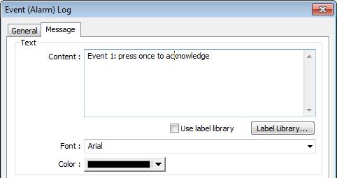
134 13-134


135 Event Display Overview Event Display object is used to display event messages which are defined in Event (Alarm) Log and have met a trigger condition. The triggered events are displayed in the chronological order. Event Display object displays: the date and time the event occurs, the time the event is acknowledged, the time the event returns to normal, the event message, the occurrence count, and the elapsed time. Multi-lined messages can also be displayed Configuration Click [Data/History]»[ Event Display] icon on the toolbar to open an Event Display object property dialog box. Set up the properties, press OK button, and a new Event Display object will be created.
![13-136 General Tab 13.22.2.1. emt, ie, XE, mtv Series Setting Mode Acknowledge address Description The available modes are: [Real-time] and [History].](/docs-images/93/114502123/images/136-0.jpg "Real-time All the events triggered since HMI starts up are displayed. History The system reads the event log in HMI memory and displays them. The content can be updated by changing window.")
136 General Tab emt, ie, XE, mtv Series Setting Mode Acknowledge address Description The available modes are: [Real-time] and [History]. Real-time All the events triggered since HMI starts up are displayed. History The system reads the event log in HMI memory and displays them. The content can be updated by changing window. In case when the trend display shows history data from today, the display will refresh once per second. When in Real-time mode, and an event is acknowledged by touching an active display line, the [Acknowledge value] specified in Event (Alarm) Log object, Message tab, is output to the [Acknowledge address] of Event Display object. For more information, see 7 Event Log.
137 History Control When in History mode, and if: [Enable reading multiple histories] is not selected Daily event log files can be displayed. A history control address can be designated. The value in the designated register is used as an index to select historical files. Index value 0 displays the latest file. Index value 1 displays the second latest file. Index value 2 displays the third latest file, and so on. If control address to LW-100, and four data log exist with dates: EL_ evt, EL_ evt, EL_ evt, and EL_ evt. Each index value in the control word corresponds to a record according to the table below: Value in LW-100 The corresponding record 0 EL_ evt 1 EL_ evt 2 EL_ evt 3 EL_ evt [Enable reading multiple histories] is selected Displays a list of events triggered in multiple days. If [History control] address is set to LW-n, the LW-n to LW-n+1 form a range of log selection. Please note that the control address leads to different results in Number of days mode and in Index of the last history mode. Number of days Display range is determined by the value in control address. [LW-n] marks the number of days from today as the start date of display, and [LW-n+1] marks the number of days preceding the start date, inclusive of the start date, as the end date. Example: If today were 2010/6/10, and the value in LW-n is 1, LW-n+1 is 3, then the data range will start from 1 day from today (LW-n = 1), which is (yesterday) in this case, and include data for the preceding 3 days, inclusive of As a result, the data displayed should be ~ Since does not exist in this example, the data displayed will be from and Index of the last history The value in control address [LW-n] marks the index value of the
![13-138 record to start, and the value in [LW-n+1] marks the index value of the record to end. If LW-n = 1, and LW-n+1 = 3, the data displayed will include data No.1, No.2, No.3. Control address Scrolling control address Please note that the value in [LW-n+1] must be greater than the value in [LW-n], to form a valid range.](/docs-images/93/114502123/images/138-0.jpg "The maximum size of data that can be displayed is 4MB; the exceeding part will be ignored. The following shows how data will be stored when the data size is too big. 5 history data, each 0.")
138 record to start, and the value in [LW-n+1] marks the index value of the record to end. If LW-n = 1, and LW-n+1 = 3, the data displayed will include data No.1, No.2, No.3. Control address Scrolling control address Please note that the value in [LW-n+1] must be greater than the value in [LW-n], to form a valid range. The maximum size of data that can be displayed is 4MB; the exceeding part will be ignored. The following shows how data will be stored when the data size is too big. 5 history data, each 0.5MB Data displayed: 8 x 0.5MB 5 history data, each 1MB Data displayed: 4 x 1MB 5 history data, each 1.5MB Data displayed: 2 x 1.5MB+1 x 1MB (partial) Enable event management If this check box is selected, writing a specific value into register LW-n and LW-n+1, where n is an arbitrary number, will control [Event Display] object with different commands as shown below: Address Value Command LW-n 0 Display all events. 1 Hide [Confirmed] events. 2 Hide [Recovered] events. 3 Hide [Confirmed] or [Recovered] events. 4 Hide [Confirmed] and [Recovered] events. LW-n+1 1 Delete a single selected event. If enabled, the value in the designated control address indicates the number of lines to be scrolled down. The minimal value is 0, which indicates the first line. In the following figure, there are 10 events recorded in the object, and value 3 is set at the control address. The upper event object displays the events in time ascending order, and begins at the 4 th event; on the other hand, the lower one displays the events in time descending order, and begins at the 7 th event.
![13-139 If [Scrolling control address] is enabled, the scroll bar](/docs-images/93/114502123/images/139-0.jpg "cannot be used for scrolling, but still shows the relative")


139 If [Scrolling control address] is enabled, the scroll bar cannot be used for scrolling, but still shows the relative position of the content. If the control address holds a value that is larger than the total number of lines, the display will stroll to the end cmt Series For cmt Series, all the events occur are displayed and updated in real-time. Press the filter icon in the upper-right corner of the object and set the start and end date. If the dates are not set, all the events are displayed.
 Log object.")

140 Event Display Tab cmt Series emt, ie, XE, mtv Series Setting Include categories Acknowledge style (emt, ie, XE, mtv Series) Max. event no. (emt, ie, Description Events in the selected category will be displayed. The categories are set in Event (Alarm) Log object. For example, if the category is set to 2 to 4 here, only events in categories 2, 3, 4 will be displayed. For more information, see 7 Event Log. Select [Click] or [Double Click] to acknowledge each single event. When an event occurs the user can tap the event line once or twice to acknowledge the new event. When acknowledged, the text color of the event will change to the selected color, and the acknowledge value associated with that event will be sent to the register designated in [Acknowledge address]. If the address is set to LW-100, and the acknowledge value is set to 31, when user acknowledges the event, value 31 is written to LW-100. This can be used in conjunction with Indirect Window object so that when an event is acknowledged, the corresponding message window is displayed. The maximum number of events to be displayed in this Event Display object. When the number of the displayed events equals to

 When using Event Display object and select History mode, the background color of the history record")
 The column width automatically adjusts to the size of the content.")
141 XE, mtv Series) Color the set maximum number, the new coming event will overwrite the latest event. Different colors indicate different event states, such as acknowledged, returns to normal, or selected. The system draws a highlight box around the latest selected event. History background (emt, ie, XE, mtv) When using Event Display object and select History mode, the background color of the history record can be customized. Grid Caption (cmt Series) Displays a grid of rows and columns in the object. The color of the grid lines can be selected. Auto fit short column (cmt Series Default style) The column width automatically adjusts to the size of the content. Available styles are: Default, Crystal, and Flat. With [Use caption] enabled, the font size, color, and name of the caption can be specified for Recipt View object.
. Time descending Latest event is placed first in the list (the top).")

142 Sort Tab Setting Sort Order & Characters Date Time Description Time ascending Latest event is placed last in the list (the bottom). Time descending Latest event is placed first in the list (the top). Select the items to be displayed and use the up and down arrow buttons to adjust the display order of the events. Displays the date tag with each event message. The four formats of date tag: MM/DD/YY DD/MM/YY DD/MM/YY YY/MM/DD Displays the time tag with each event message. The four formats of time tag: HH:MM:SS HH:MM DD:HH:MM HH
143 Security Tab Setting Interlock User restriction Description When [Use interlock function] check box is selected, whether the object is operable is determined by the state of a designated Bit address. As shown in the above settings, if LB-0 is ON, the object is operable. Hide when disabled When the designated Bit is OFF, the object will be hidden. Set the security class of the object to be operated by an authorized user. Object class None means any user can operate this object. Only account admin can operate Administrator object class. Make invisible while protected When the user's privilege does not match the object class, the object will be hidden.


144 When this check box is deselected, the unauthorized user can see the Event Display object, but cannot trigger the object or make any change. Font Tab In Real-time mode: Users may select Italic font and set the font size. The font is displayed according to the setting in Event Log object. In History mode: Users may select Italic font and set the font size, font and color, or tick the [Font from label library] check box. Empty Warning When [Use empty warning] is enabled, the text displayed when no event has occurred can be specified.

] icon on the toolbar to open the property dialog box.")
145 Data Transfer (Trigger-based) Overview Data Transfer (Trigger-based) object can transfer values from the source register to the destination register. The data transfer operation can be activated by changing the state of the designated bit register, or by manually pressing the object. For cmt Series, only touch trigger mode is available Configuration Click [Object]» [Data Transfer]» [Data Transfer (Trigger-based)] icon on the toolbar to open the property dialog box. Set up the properties, press OK button, and a new Data Transfer (Trigger-based) object will be created. General Tab cmt Series emt, ie, XE, mtv Series
146 Setting Source address Destination address Attribute Trigger address Notification Description Data Transfer object reads the data from [Source Address]. Data Transfer object writes the data to [Destination Address]. No. of words The number of words to be transferred from [Source Address] to [Destination Address]. The unit is word. Mode Touch trigger Press the object to activate data transfer operation. External trigger The data transfer operation is activated when the state of the designated bit address changes. There is a further selection to make of whether the data transfer operation is activated after Off to ON, ON to OFF transition, or at both of the changes of state. Specify a bit address for [External trigger] mode. When enabled, the system will set the designated address ON or OFF when it s ready for data transfer. Follow The notification bit will reset to its original state once the system starts data transfer. Note When using Data Transfer Trigger Based object, place the control bit addresses in the same window in order to trigger Data Transfer. If the Data Transfer Trigger Based object is placed in the common window, when the state of the control bit addresses placed in any window changes, Data Transfer is triggered.
147 Backup Overview Backup (Trigger-based) object and Backup (Global) object can transmit recipe data (RW, RW_A), event log, recipe database, sampling data, and operation log to an external device (SD card, USB disk), in a specified time range or format. For example, when the event log is saved in a SD card, a USB disk can be inserted when HMI power is still ON, and use Backup object to copy the data into USB disk from SD card, and then remove USB disk without turning off HMI power. The data saved in USB disk can be used on PC for analyzing. When the system is backing up, the state of system register [LB-9039] is set ON. With [ ] option, information can be sent to configured contacts. Backup (Trigger-based) object is triggered by pressing the object on the screen while Backup (Global) object runs in the background regardless of screens being viewed. Backup (Global) object is available only on cmt Series models Configuration On the toolbar click [Object]» [File Operation] to find [Backup (Trigger-based)] and [Backup (Global) objects. Open [Backup (Trigger-based)] object property dialog box, set up the properties, press OK button, and a new Backup (Trigger-based) object will be created. When using a cmt Series model, [Backup (Global)] object is available. Open [Backup (Global)] object managing dialog box, click [New] to open the object property dialog box, set up the properties, press OK button, and a new Backup (Global) object will be created.


148 General Tab Backup (Trigger-based) cmt Series emt, ie, XE, mtv Series Backup (Global) cmt Series
![13-149 Setting Source Backup position Save format Description [RW], [RW_A], [Recipe database], [Historical event log], [Historical data sampling], [Operation log] Select one from the above for the](/docs-images/93/114502123/images/149-0.jpg "source. When backing up [Historical data log], use [Data Sampling object index] to select the one to back up. Options other than RW, RW_A will be available only when they are used in the project file.")
149 Setting Source Backup position Save format Description [RW], [RW_A], [Recipe database], [Historical event log], [Historical data sampling], [Operation log] Select one from the above for the source. When backing up [Historical data log], use [Data Sampling object index] to select the one to back up. Options other than RW, RW_A will be available only when they are used in the project file. Select the destination where the source files will be saved to. SD card / USB disk The external device connected to HMI. If using cmt series, SD card and USB disk can only save [RW], [RW_A], and [Recipe database]. Remote printer/backup server (emt, ie, XE, mtv Series) To select this, enable MT remote printer/backup server at: [Menu]» [Edit]» [System Parameters]» [Printer/Backup Server]. Please note that [Operation log] backup can only be saved to Remote printer/backup server. To save into a SD card or USB drive, please use the control address of Operation Log object. For more information, see 26 EasyPrinter. To use , go to [System Parameters]» [ ] tab to configure first. And then go to Backup object» [ ] tab to configure the recipient address, subject, and message. Select the desired format to back up the file. emt, ie, XE, mtv Series: HMI Event Log File (.evt) / HMI Data Log File (.dtl) Comma Separated Values (.csv) The [Event] column is included in the backup file to indicate the type of the event. 0 = Event is triggered 1 = Event is acknowledged 2 = Event returns to normal
 (Only for backup to e-mail) Comma Separated Values (.csv) Add BOM (Byte Order Mark) to file header for EXCEL can interpreting non-ascii strings correctly. When back up event log in.")
150 EasyConverter can be used to easily convert HMI Event Log File (.evt) and HMI Data Log File (.dtl) to.xls or.csv format. SQLite Database File (.db) cmt Series: SQLite Database File (.db) (Only for backup to ) Comma Separated Values (.csv) Add BOM (Byte Order Mark) to file header for EXCEL can interpreting non-ascii strings correctly. When back up event log in.csv format, open the csv file in EXCEL. The BOM (Byte Order Mark) can be added to the file header so that the.csv file containing non-ascii strings can directly be opened in EXCEL. The title, export time, occurrence count, and elapsed time can be included or omitted in the backed-up.csv file. Event category range Range Trigger This groupbox will be available only when backing up a historical event log in CSV format. Two options can be found in this group box: All and Partial. Selecting partial and entering 3, 5, 8 in the field will backup events in categories 3, 5, and 8. Selecting partial and entering 3-8 will backup events in categories 3 to 8. Historical data sampling Select a number of files. For example, if [Start] is set to [Current], and [Within] is set to [5 file(s)], the latest five files in memory will be backed up. Historical eventlog Select a number of days. For example, if [Start] is set to [Yesterday], and [Within] is set to [2 day(s)], the files obtained yesterday and the day before yesterday will be backed up. Select [All] to save all files, and the maximum is 90 days. Mode There are three ways to activate Backup function. Touch trigger Touch the Backup object to activate backup operation. External trigger (bit)
 Users can specify the number of days to backup data using [Trigger address].")
151 Register a bit device to trigger the backup operation. Select whether the backup operation is activated after Off to ON, ON to OFF transition, or at both of the changes of state. External trigger (word) Users can specify the number of days to backup data using [Trigger address]. [Trigger address] usage (suppose LW-n is used): LW-n: Will start to back up when the value changes from 0 to 1. LW-n+1: The start date of backup. LW-n+2: The number of days for backup. (The maximum: 90 days). Trigger address On cmt-svr, Backup (Trigger-based) object only supports [Touch trigger] mode but not [External trigger (bit)] and [External trigger (word)] modes. When the state of the designated register is set ON, the backup operation is activated. When the backup operation is done, the state of the designated register is set OFF. Note All history files should have been saved in memory, either HMI memory, USB disk or SD card. Otherwise, the Backup object will not work. The maximum number of days for backup is 90 days. (Not including cmt Series) When saving files to USB disk or SD card, the capacity of a FAT32 folder depends on the length of the file names. Fewer files can be saved when the file names are longer. For cmt Series, see 7 Event Log and 8 Data Sampling that explain the mechanism of synchronizing data to external device.

152 Advance Tab (emt, ie, XE, mtv) Setting Serial number Options Description If enabled, when backing up history files, a user-defined, 5-digit serial number can be appended to the end of the file name of the history data backup. The serial number is determined by the value in the designated source address. After backup, the value of this LW address will automatically increment by 1. The range of the serial number is 0~65535 For example, if the serial number is 123, the appended 5 digits will be A data sampling file dtl will be backed up as dtl. An event log file evt will be backed up as evt. Remove old files after backup If selected, the old history files will be removed after backup. Note cmt Series does not support Advance settings.

153 Tab Setting Add.txt extension to the filename to skip the anti-virus detection Recipients, Subject, Message Description If selected, when sending backup data as an attachment, the filename extension.txt will be added to the file name. This prevents the mail server or anti-virus software from blocking s. Back up the address of the recipients, the subject of the , and the message content.


154 Media Player Overview At the first time using Media Player object in the project, download the project to HMI via Ethernet. EasyBuilder Pro installs Media Player driver automatically. Media Player object plays video files with controls such as seek, zoom, and volume adjustment to provide maintenance instructions or procedures on video so as to enable on-site operators to perform tasks efficiently. This object does not work remotely on cmt Viewer Configuration Click [Object]» [Media Player] icon on the toolbar to open a Media Player object property dialog box. Set up the properties, press OK button, and a new Media Player object will be created. General Tab cmt (excluding cmt-svr, cmt-hdm, cmt-fhd) emt, XE
155 Setting Use UI control Control address Ext. device Attribute Description Use media control provided by user interface. Resume previous playback / Resume after restart Resume Media Player when changing from another window to the window where Media Player is. Selected Designate a word register to control the object operations. Not selected No manual control. Video will be played automatically when the designated window opens. Command (control address + 0) Enter a value in the Command register to designate which action is executed. Parameter 1 (control address + 1) Enter a value in Parameter 1 associated with each command action. Parameter 2 (control address + 2) Enter a value in Parameter 2 associated with each command action. Status (control address + 3) Indicates the status or errors. File index (control address + 4) The file number in the designated folder. It is recommended to file the video name with a number. Start time (control address + 5) The start time of the video (second). 0, normally. End time (control address + 6) The end time of the video (second). (The time length of the video) Update video playing time If enabled, the elapsed playing time of video will be written into [Playing time] register at a rate set by [Update period] in seconds. Update period Update period of [Playing time], range from 1 to 60 (second). Playing time (control address + 7) The elapsed playing time of video (Second). Normally between start time and end time. Play video files in SD card / USB disk. Folder name The folder name of video files stored in SD card or USB disk. Files must be stored in root directory. Subdirectories won t be accepted. (For example, example\ex is an invalid directory.) [Folder name] cannot be empty, must be alpha-numeric, and all in ASCII character. Auto. repeat
156 When finish playing all the video files, replay from the first file. Ex: Video 1 > Video 2 > Video 1 > Video 2 Background The background color of the object. Note The data format for control address is 16-bit Unsigned or 16-bit Signed. If using 32-bit Unsigned or 32-bit Signed, only the previous 16 bits will be effective. Control command The following are the settings of different commands. Play index file [Command] = 1 [Parameter 1] = file index [Parameter 2] = ignore (set 0) Note Files are stored with file names in ascending order. If the file cannot be found, [Status] bit 8 is set ON. Please stop the playing video before switching to another. Play previous file [Command] = 2 [Parameter 1] = ignore (set 0) [Parameter 2] = ignore (set 0) Note If [File index] is zero, the same file is replayed. If the file cannot be found, [Status] bit 8 is set ON. Play next file [Command] = 3 [Parameter 1] = ignore (set 0) [Parameter 2] = ignore (set 0) If there are no more files, the index 0 file is played. If the file cannot be found, [Status] bit 8 is set ON. Pause / Play Switch [Command] = 4 [Parameter 1] = ignore (set 0)
157 [Parameter 2] = ignore (set 0) Stop playing and close file [Command] = 5 [Parameter 1] = ignore (set 0) [Parameter 2] = ignore (set 0) Start playing from the designated time [Command] = 6 [Parameter 1] = target time (second) [Parameter 2] = ignore (set 0) Note Parameter 1 (target time) must be less than the ending of time or it plays the last second. Forward [Command] = 7 [Parameter 1] = target time (second) [Parameter 2] = ignore (set 0) Note Going forward to the designated second in [Parameter 1]. If the video is paused, the forwarding action will be started by playing. When the designed time is later than the end time, it plays the last second. Backward [Command] = 8 [Parameter 1] = target time (second) [Parameter 2] = ignore (set 0) Note Going Backward to the designated second in [Parameter 1], if the video is paused, the backward action will be started by playing. When the designed time is earlier than the beginning time, it plays from beginning. Adjust volume [Command] = 9 [Parameter 1] = volume (0 ~ 128) [Parameter 2] = ignore (set 0)
![13-158 Note Default volume is 128. Set video display size [Command] = 10 [Parameter 1] = display size (0 ~ 16) [Parameter 2] = ignore (set 0) Note [Parameter 1 = 0]:Fit video image to object size.](/docs-images/93/114502123/images/158-0.jpg "[Parameter 1 = 1 ~ 16]:Magnification from 25% ~ 400% in 25% increments where 1 = 25%, 2 = 50%, 3 = 75% and so on.")
158 Note Default volume is 128. Set video display size [Command] = 10 [Parameter 1] = display size (0 ~ 16) [Parameter 2] = ignore (set 0) Note [Parameter 1 = 0]:Fit video image to object size. [Parameter 1 = 1 ~ 16]:Magnification from 25% ~ 400% in 25% increments where 1 = 25%, 2 = 50%, 3 = 75% and so on. Status (control address + 3) When playing a video the system sets [File Open (bit00)] and [File Playing (bit01)] to ON. If the file cannot be found, or an invalid command is entered, the Command Error bit 08 is set ON. If the file format is not supported, or a disk I/O error occurs, during playback (for example, USB disk unplugged), the File Error bit 09 is set ON. 00: File Opened / Closed (0 = closed, 1 = opened) 01: File Playing (0 = not playing, 1 = playing) 08: Command Error (0 = accepted, 1 = incorrect) 09: File Error (0 = accepted, 1 = incorrect) Note The figure shows the status value associated with each state: Stop = 0, Pause = 1, Playing = 3 [Command], [Parameter 1], and [Parameter 2] are write addresses. All others are read only.
 Select to start playing video or pausing. Stop playing and close the video file.")
159 Preview Tab Users can test whether the video format is supported by using the preview function. Setting Forward << / Backward >> Play / Pause Stop Load Description Go forward or backward of the video. (in minutes) Select to start playing video or pausing. Stop playing and close the video file. To test another video, please stop playing the current video first. Select a video to preview. Note Only one video file can be played at one time. If [control address] is not enabled and [Auto. repeat] is not selected, after finish playing the first file, the system will stop playing and close the video file. If [control address] is not enabled, the system will find the first file in the designated folder and start to play (in ascending order of the file name). If the file can be previewed, the format is supported. If the video image quality is poor, please adjust the resolution. The supported formats: mpeg4, xvid, flv etc. Click the icon to download the demo project. Please confirm your internet connection before downloading the demo project.
160 Data Transfer Overview Data Transfer (Time-based) object has similar function compared to Data Transfer (Trigger-based) object. They transfer the data from source to destination register. The difference is that Data Transfer (Time-based) object transfers data based on time schedule, and is able to transfer data in bits. When using cmt Series, Data Transfer (Time-based) object is divided into two modes: [Time-based] and [Bit trigger]. In these two modes, the system automatically detects the state of the designated bit register and executes data transfer. [Time-based] mode is the same as described earlier, where [Bit trigger] mode transfers data when the state of the designated bit register changes. For the detail of [Bit trigger] mode, see Data Transfer Bit Trigger Configuration Click [Object]» [Data Transfer]» [Data Transfer (Time-based)] icon on the toolbar to open the Data Transfer management dialog box. Click [New] and configure the properties. All the defined Data Transfer can be viewed from the dialog box as shown in the following figure. emt, ie, XE, mtv Series
![13-161 cmt Series 13.26.2.1. Data Transfer Time-based General Tab Click the [New] button in the Data Transfer management dialog box.](/docs-images/93/114502123/images/161-0.jpg "Setting Attribute Description Address type Select the data type, either [Bit] or [Word]. No. of bits /No.")
![of words When [Bit] is selected in [Address type], set the number of bits transferred each time when data transfer is](/docs-images/93/114502123/images/161-1.jpg "triggered.")
161 cmt Series Data Transfer Time-based General Tab Click the [New] button in the Data Transfer management dialog box. Setting Attribute Description Address type Select the data type, either [Bit] or [Word]. No. of bits /No. of words When [Bit] is selected in [Address type], set the number of bits transferred each time when data transfer is triggered. When [Word] is selected in [Address type], set the number of words transferred each time when data transfer is triggered.
162 Activate only when designated window opened Source address Destination address Notification Interval Select the time interval of data transfer, for example, when 3 seconds is set, the system will transfer data every 3 seconds. Specifying a short time interval or a big number of data to transfer may cause an overall performance of system decrease. Therefore, it is recommended that users choose a longer time interval and a smaller amount of data to transfer. When a short interval is inevitable, be aware of the interval must be longer than the data transfer operation. For example, if the data transfer operation takes 2 seconds, set the interval longer than 2 seconds. Data Transfer object transfers data only when the designated window is opened. Data Transfer object reads the data from [Source Address]. Data Transfer object writes the data to [Destination Address]. When enabled, the system will set the designated address ON or OFF when it s ready for data transfer. Follow The notification bit will reset to its original state once the system starts data transfer Data Transfer Bit Trigger General Tab Click the [New] button in the Data Transfer management dialog box, and open [Bit trigger] tab.
![13-163 Setting Source address Destination address No. of word Trigger address Notification Description Data Transfer object reads the data from [Source Address].](/docs-images/93/114502123/images/163-0.jpg "Data Transfer object writes the data to [Destination Address]. Set the number of words transferred each time when data transfer is triggered.")
163 Setting Source address Destination address No. of word Trigger address Notification Description Data Transfer object reads the data from [Source Address]. Data Transfer object writes the data to [Destination Address]. Set the number of words transferred each time when data transfer is triggered. Set the register that controls data transfer and select the trigger mode. Trigger mode Trigger data transfer when the state of the designated register changes from Off to ON, ON to OFF, or at both of the changes of state. When enabled, the system will set the designated address ON or OFF when it s ready for data transfer. Follow The notification bit will reset to its original state once the system starts data transfer.
![13-164 13.27. PLC Control 13.27.1. Overview PLC Control object can execute commands when it is triggered. 13.27.2. Configuration Click [Object]» [PLC Control] icon on the toolbar to open the PLC Control Object management dialog box.](/docs-images/93/114502123/images/164-0.jpg "To add a PLC Control object, click [New], set up the properties, press OK button and a new PLC Control object will be created. Click [New] and the following dialog box appears. See 13.")
![27.2.1 Type of Control. Note The [General PLC Control] option is not available for cmt Series.](/docs-images/93/114502123/images/164-1.jpg "Triggering [Screen hardcopy] in cmt Viewer will result in files being saved into the USB disk / SD card connected to the cmt HMI.")
164 PLC Control Overview PLC Control object can execute commands when it is triggered Configuration Click [Object]» [PLC Control] icon on the toolbar to open the PLC Control Object management dialog box. To add a PLC Control object, click [New], set up the properties, press OK button and a new PLC Control object will be created. Click [New] and the following dialog box appears. See Type of Control. Note The [General PLC Control] option is not available for cmt Series. Triggering [Screen hardcopy] in cmt Viewer will result in files being saved into the USB disk / SD card connected to the cmt HMI. Likewise, the [Back light control] option in cmt Viewer will control the backlight of the HMI itself.
![13-165 Selecting [Change window] or [General PLC Control] as [Type of control] will require more than one trigger word (consecutive).](/docs-images/93/114502123/images/165-0.jpg "Using a user-defined tag PLC will require declaring an array datatype. 13")
165 Selecting [Change window] or [General PLC Control] as [Type of control] will require more than one trigger word (consecutive). Using a user-defined tag PLC will require declaring an array datatype Type of Control Change window Setting Active only when designated window opened Turn on back light Clear data after window changed Use window no. offset Description Allow this operation only if a particular screen is displayed. The backlight is turned ON when the window object is changed. (Not available for cmt Series) Reset the value at trigger address to zero when the window object is changed. If [Use window no. offset] is selected, this option will only show when a negative offset is used. Select the check box and select a window offset, the new window no. to change to will be the value in [Trigger address] plus the offset. For example, if [Trigger address] is LW-0 and offset is set to -10. When the value in LW-0 is 25, the system will change to window no. 15 (25-10=15). The range of the offset is to Note If [LB-9017] is set ON, the write-back function will be disabled, the new window number is not written back into a designated address. Place a valid window number in the designated trigger address to change the base screen to
166 the new window number. The new window number is written back into the designated address. For example, if current window is window no. 10, and [Trigger address] is set to LW-0, When LW-0 is changed to 11, the system will change the current window to window no. 11, and then write 11 to LW-1. When the window is changed, the new window number is written back into the address that is calculated by [Trigger address] and the data format, as shown in following table. Data Format Trigger address Write address 16-bit BCD Address Address bit BCD Address Address bit Unsigned Address Address bit Signed Address Address bit Unsigned Address Address bit Signed Address Address + 2 Write data to PLC (current base window) Each time the base window is changed, the new window number will be written into the [Trigger address]. If [Use window no. offset] is selected, the window number of the base window plus the window number offset will be written into the [Trigger address]. General PLC Control (emt, ie, XE, mtv) Transfer word data blocks from PLC to HMI, and vise-versa, and the transfer direction is controlled by the value in the [Trigger address]. Value in Action [Trigger address] 1 Transfer data from PLC register HMI RW register 2 Transfer data from PLC register HMI LW register 3 Transfer data from HMI RW register PLC register 4 Transfer data from HMI LW register PLC register Four consecutive word registers are used as described in the following table: Address Purpose Description [Trigger address] Determine the direction of data transfer The valid values are listed in the above table. When a new control code is written into the register, HMI will start to transfer. After data transfer is finished, the value will
167 [Trigger address] +1 [Trigger address] +2 [Trigger address] +3 The size of data to transfer. Offset to the start address of PLC register Offset to the start address of LW or RW memory in HMI be set to 0. The unit is word. Assume the value is n, where n is an arbitrary number, the start address of PLC register is [Trigger address n]. Take an OMRON PLC as an example: If [Trigger address] uses DM-100, [Trigger address + 2] will be DM-102. If the value in DM-102 is 5, the start address of data source would be DM-109 ( = 109). Take OMRON PLC as an example: If set [Trigger address] to DM-100, [Trigger address + 3] will be DM-103. If the value in DM-103 is 100, the start address of memory in HMI is RW-100 or LW-100. Example 1 To use PLC Control object to transfer 16 words data in OMRON PLC, starting from address DM-100, to the HMI address, starting from RW-200. The setting is shown below: 1. Firstly, create a PLC Control object, set [Type of control] to [General PLC control], and set [Trigger address] to DM-10, that is, to use the four sequential registers start from DM-10 to control data transfer. 2. Confirm the data size and the offset addresses. Set DM-11 to 16, since the number of words to transfer is 16 words. Set DM-12 to 86, which indicates the address of data source is DM-100 (100= ). Set DM-13 to 200, which indicates the destination address is RW Set DM-10 according to the direction of data transfer. If set DM-10 to 1, the data will be transferred from PLC to HMI RW register, If set DM-10 to 3, the data will be transferred from HMI RW register to PLC. Back light control (write back) When [Trigger address] is turned ON, HMI backlight will be turned ON/OFF and [Trigger
![13-168 address] will be turned OFF. Any touch on the screen will turn the backlight on.](/docs-images/93/114502123/images/168-0.jpg "Back light control When [Trigger address] is turned ON, HMI backlight will turn ON/OFF and the state of [Trigger address] will not be changed.")
168 address] will be turned OFF. Any touch on the screen will turn the backlight on. Back light control When [Trigger address] is turned ON, HMI backlight will turn ON/OFF and the state of [Trigger address] will not be changed. Sound control When the state of the designated [Trigger address] changes, the HMI will play the sound selected from the sound library. There is a further selection determines whether the sound is played after Off to ON, ON to OFF transition, or at both of the changes of state. Execute macro program Select a pre-defined Macro from the drop-down list. When the state of the designated [Trigger address] changes, the selected Macro is executed. There is a further selection determines whether the Macro is executed after Off to ON, ON to OFF transition, or at both of the changes of state. If select [Always active when ON], the macro will be executed repeatedly. (The shortest time interval between runs is 0.5 second.) Screen hardcopy When the state of the designated [Trigger address] changes, print the selected screen. If select [SD card] or [USB disk] as [Printer], a hardcopy folder will be generated in the selected external device for saving the printed screen in JPG format. The name of the JPG files starts from yyyymmdd_0000. To print the screen using a printer, go to System Parameter Settings» Model tab and set the
169 printer. To print the screen using a remote printer, go to System Parameter Settings» Printer/Backup Server tab and configure the parameters. There are three options to specify the source window for hardcopy: Current base window Print the base window currently opened. Window no. from register Print the window designated by the value in a designated word address. Designate window no. Directly select a window to be printed. Customized File Handling This feature can be used to customize naming of the folders and the JPG files. Setting Description Folder name The folder name can be an alphanumeric name, and certain half-width symbols are allowed:!@#$%^&()_+{}`-=;',. The folder name can also be specified by a naming syntax. Dynamic format The folder names can be set by a designated word address, or by a naming syntax indicating the current system time. The syntax can be specified by selecting time buttons or entering the syntax in Format field. The length limit is from 1 to 25. Note: Up to 10 layers of folders can be created. The exceeding layers will be ignored. File name The way to specify a file name is similar to specifying a folder name. Note: If the file name already exists, the system will add _0001 to the file name as a serial number. The numbers of the later files add up until _9999. The files after _9999 will be ignored. For example, if the three file names exist: A.jpg, A_0001.jpg, A_0003.jpg. When trigger screen hardcopy with the same file name, the coming files will be named in this order: A_0002.jpg, A_0004.jpg, A_0005.jpg, and so on.
170 Note A background printing procedure is performed when the printed window is not the current base window. If the hard-copied window is a background window, its [Direct Window] and [Indirect Window] objects will not be printed. When using a dynamic format name, the system will use a _ sign as a substitute for invalid symbols. When using a dynamic format name, if screen hardcopy is triggered without specifying the format first, the system will save the file in the default directory, which is: hardcopy\yymmdd_0000.jpg
![13-171 13.28. Scheduler 13.28.1. Overview Scheduler object turns bits ON/OFF, or writes values to word registers at designated start times. It works on a weekly basis. 13.28.2. Configuration Click [Object]» [Time-related]» [Scheduler] icon on the toolbar to open the Scheduler management dialog box, click [New] to open the Scheduler property setting dialog box.](/docs-images/93/114502123/images/171-1.jpg "The following two demonstrations explain the usage of Scheduler. Example 1 A motor is scheduled to power - ON at 9:00 and power OFF at 18:00, Monday to Friday.")
171 Scheduler Overview Scheduler object turns bits ON/OFF, or writes values to word registers at designated start times. It works on a weekly basis Configuration Click [Object]» [Time-related]» [Scheduler] icon on the toolbar to open the Scheduler management dialog box, click [New] to open the Scheduler property setting dialog box. The following two demonstrations explain the usage of Scheduler. Example 1 A motor is scheduled to power - ON at 9:00 and power OFF at 18:00, Monday to Friday. We are using LB-100 to control the motor state. LB-100 will be set ON at 9:00 and OFF at 18: Click the Scheduler icon on the toolbar to open the Scheduler management dialog box, click [New]. 2. In [General] tab, select [Bit ON] in [Action mode] and set [Action address] to LB In [Time Set] tab, select [Constant].
![13-172 4. Enter [Start] time as 9:00:00 and select Monday to Friday. Do not select [Setting on individual day]. 5. Enter [End] time as 18:00:00 and select [Enable termination action] check box. 6.](/docs-images/93/114502123/images/172-0.jpg "Click [OK], a new Scheduler object will be created on the [Scheduler] list. Example 2 A thermal heater is scheduled to heat up to 90 C at 08:00 and cool down to 30 C at 17:00, Monday to Friday.")
![LW-100 is used to store the set point value. 1. Click the Scheduler icon on the toolbar to open the Scheduler management dialog box, click [New]. 2.](/docs-images/93/114502123/images/172-2.jpg "In [General] tab, select [Word write] in [Action mode] and set [Action address] to LW-100. 3. Select [Constant] for [Word write value settings] and enter 90 in [Start value]. 4.")
172 Enter [Start] time as 9:00:00 and select Monday to Friday. Do not select [Setting on individual day]. 5. Enter [End] time as 18:00:00 and select [Enable termination action] check box. 6. Click [OK], a new Scheduler object will be created on the [Scheduler] list. Example 2 A thermal heater is scheduled to heat up to 90 C at 08:00 and cool down to 30 C at 17:00, Monday to Friday. LW-100 is used to store the set point value. 1. Click the Scheduler icon on the toolbar to open the Scheduler management dialog box, click [New]. 2. In [General] tab, select [Word write] in [Action mode] and set [Action address] to LW Select [Constant] for [Word write value settings] and enter 90 in [Start value]. 4. In [Time set] tab select [Constant]. 5. Enter [Start] time as 8:00:00 and select Monday to Friday. Do not select [Setting on individual day]. 6. Enter [End] time as 17:00:00 and select [Enable termination action] check box. 7. Return to [General] tab and enter 30 in [End value]. 8. Click [OK], a new schedule object will be created on the [Scheduler] list.
173 General Tab Setting Power ON start/end action Description Execute the defined action when the HMI is powered ON. Enabled When HMI is powered ON within the scheduled time range, the start action will be performed automatically. When HMI is powered ON outside the scheduled time range, the termination action will be executed. Disabled When the HMI is powered ON at a time later than the start time, the start action will not be performed, but the termination action will be performed. When the termination action is not defined, the scheduled range is not recognized and no action is performed.
174 Action mode Choose the action to do at the given time. Bit ON At the start time, set the designated bit ON. At the end time, set the designated bit OFF. Example: Start time : 09:00:00 End time : 17:00:00 Bit OFF At the start time, set the designated bit OFF. At the end time, set the designated bit ON. Example: Start time : 09:00:00 End time : 17:00:00 Word write The [Write start value] entered here is transferred to the designated [Action address] word register at the start time. At end time, the [Write end value] entered here is written to the [Action address]. The valued can be entered manually or be set by using [Address] mode. In [Address] mode, the value in the specified address is the start value where the value in [Address + 1] is the end value. Example: Device address: LW-100 Start time: 09:00:00 End time: 17:00:00 Write start value: 10 Write end value: 0 Use register: If control address is LW-n, then enter 10 in LW-n and enter 0 in LW-(n+1).
![13-175 Note Only is an [End time] is set in the [Time set] tab will](/docs-images/93/114502123/images/175-1.jpg "the [Write end value] box appear.")

![[Address] allows controlling the time by the designated address.](/docs-images/93/114502123/images/175-4.jpg "Constant Setting on individual day If [Setting on individual day] is")
175 Note Only is an [End time] is set in the [Time set] tab will the [Write end value] box appear. Time Set Specify start time and end time. [Constant] allows specifying a date or period and time. [Address] allows controlling the time by the designated address. Constant Setting on individual day If [Setting on individual day] is selected The same start time and end time can be assigned to different days of the week.


176 Note Start and end time must be entered. Start and end time must be on a different time, or same time but different day. If [Setting on individual day] is not selected Start time and end time entered must start and end within 24-hours. Note Start time and end time must be on a different time, different day. If an end time is earlier than a start time, the end action will occur in the next day. Address The scheduler object retrieves the start/end time and day of week information from word registers, enabling all parameters to be set and changed under PLC or user control. Designated as the top address in a block of 11 sequential registers which are used to store time setting data. The format of the 11 word registers should normally be 16-unsigned integer. If a 32-bit word address is chosen, only bits 0-15 are effective, and bits should be written as zero. The following describes each register. Control (Time setting address + 0) When [Control] bit is ON, the HMI will read and update [Action mode], [Start time], and [End time] values.
177 Note HMI will not regularly read the data from [Action mode] (address + 2) to [End time] (address + 10). Please turn [Control] ON when the settings are changed. Status (Time setting address + 1) When the read operation is completed, Bit00 of this register turns ON. If time data read is out of range or incorrect in any way Bit01 turns ON. Note After the scheduler reads the data and the status is turned ON (The value in [Address + 1] = 01), the control bit must be turned OFF (address = 0). The status bit and error bit will be turned OFF (1 0) at the same time.
178 Action mode (Time setting address + 2) Enable/disable [Enable termination action] and [Setting on individual day]. Whatever the [Enable termination action] bit is, all the time data, from [Control] to [End time (second)], will be read. Note If [Enable termination action] is OFF, all 11 registers are still read but end time is ignored. If [Setting on individual day] is ON, make sure that all start end times are entered. If more than one start / end day bit is ON, and error will occur. Start/End Day (Start Day: Time setting address + 3, End Day: Time setting address + 7) Designates which day of week is used to trigger the start or end action. Start/End Time (Start Time: Time setting address + 4 to + 6, End Time: Time setting address + 8 to + 10) Hour: 0 23 Minute: 0 59 Second: 0-59 Values outside these ranges will cause error. Note 16-bit unsigned integer format must be used; BCD format is not supported here. In [Address] mode, [Control] bit should be set after HMI reboots to update scheduler time. End time depends on [Action mode] (address + 2). [Enable termination action] (Bit 00) and [Setting individual day] (Bit 01) are related:

179 Prohibit tab Before the scheduled action is performed, the HMI will read the specified bit state. If it is ON, the scheduled start/end action will be skipped. Otherwise, it will be performed normally. Note The maximum number of Scheduler objects in a project is 64. A time schedule applies one action only when the start time is reached. [Write start/end value] and [Prohibit] bit is read only once before start action. After that, even to change the state of [Prohibit] bit or [Write start/end value], the end action and the value written will not be affected. Also, to read data of [Write start/end value] and [Prohibit] bit, there is a delay of start action due to the communication. Each time RTC data is changed, scheduler list entries that possess both start and end times will be checked for in-range or out-range conditions. For in-range, the start action will occur. If the end action is not set, the new range is not recognized, the action will not occur. If several Scheduler objects are set to the same start time or end time, the action is performed in ascending order of the schedule number. In [Time Set]» [Address] mode, the system will read [Control] word regularly. The length of the period depends on the system. In [Time Set]» [Address] mode, when start time and end time is out- range, error occurs
180 in the set action time. (Note: BCD is not an acceptable format) In [Time Set]» [Address] mode, the action will not start up until the first time the time data is successfully updated.

181 Option List Overview Option List object displays a list of items that the user can view and select. Once the user selects an item, the corresponding data will be written to a word register. There are two forms of this object [List box] and [Drop-down list]. The [List box] lists all items and highlights the selected one. The [Drop-down list] normally displays only the selected item. Once the object is pressed, the system will display a list (which is similar to list box) as shown in the following figure Configuration Click [Object]» [Option List] icon on the toolbar to open an Option List object property dialog box. Set up the properties, press OK button, and a new Option List object will be created.
![13-182 General Tab Setting Attribute Monitor address Description Mode: The list style, either [List box] or [Drop-down list]. Item no.: Set the number of items for the object.](/docs-images/93/114502123/images/182-0.jpg "Each item represents a state displayed in the list and the corresponding value will be written to the [Monitor address]. Background: Set background color.")
182 General Tab Setting Attribute Monitor address Description Mode: The list style, either [List box] or [Drop-down list]. Item no.: Set the number of items for the object. Each item represents a state displayed in the list and the corresponding value will be written to the [Monitor address]. Background: Set background color. Selection: Set background color for the selected item. Source of item data: There are 4 sources available: [Predefine], [Dates of historical data], [Item address], and [User account]. See The corresponding value of the selected item will be written to [Monitor address]. Write when button is released If this check box is selected, the selected item value will be written to [Monitor address] after the button is released.

183 Send notification after writing successfully Set On/Off the designated bit address after successfully writing data to PLC. Note For cmt Series, the [Dates of historical data] and the [write when button is released] selections are not available Source of item data Predefine The list is manually defined in [Mapping] tab. The number of items can be adjusted by [Item no.], and each item represents one state. Each item has a corresponding value which will be written to [Monitor address]. Dates of historical data This selection is not available for cmt Series. Option List object can be used with historical data display objects, such as Trend Display object, History Data Display object and Event Display object to control which history file should be
 log] and [Data sampling]. Set the date format.")
184 shown. The figure below is an example of Option List used with Trend Display. Setting Type Date Data Sampling object Enable [delete history data] function Description Two options are available: [Event (Alarm) log] and [Data sampling]. Set the date format. YYYY means a four digits year (EX: 2012), YY means a two digits year (EX: 12), MM means month and DD means day. Select which Data Sampling object is displayed when [Type] is [Data Sampling], and it should be the same as the [Data sampling object index] configured in [Trend Display] or [History Data Display]. If selected, a control address can be set. Writing 1 to this address will delete the history data of the specified date. Note In [Dates of historical data] mode, since the system automatically reads the historical data and finds the date information, it is not necessary to configure in the [Mapping] tab. The error message displayed in Option List can be modified in [Mapping] tab. Item address The list will be read from the given [Item address] and controlled by [Control address]. The following options will be available:
![13-185 Setting Control address Item address Description [Address]: If the value at this address is changed to 1, the option list would be replaced by items defined at [Item address].](/docs-images/93/114502123/images/185-0.jpg "After updating, the value will be restored to 0. [Address + 1]: Define the number of items in [Item address].")
185 Setting Control address Item address Description [Address]: If the value at this address is changed to 1, the option list would be replaced by items defined at [Item address]. After updating, the value will be restored to 0. [Address + 1]: Define the number of items in [Item address]. Assign the item address UNICODE The item will use UNICODE characters, such as Chinese characters. The length of each item Define the number of letters for each item, the unit is Word. Note The UNICODE characters used here should be used by Text object, so that EasyBuilder Pro will compile the needed fonts and download these fonts to HMI, then the UNICODE letters can be correctly displayed. [The number of items] multiplied by [The Length of each item] must be less than 1024 words. The system automatically disables [Mapping] tab in [Item address] mode.
![13-186 User account If [Enhanced Security] mode is enabled, [User account] would appear in the [Source of item data] and it lists the names of users.](/docs-images/93/114502123/images/186-0.jpg "Setting Sort Display Description Select the sorting method from [Ascending] of [Descending]. If [Privilege] is selected, the privileges for each user will be displayed in option list.")
186 User account If [Enhanced Security] mode is enabled, [User account] would appear in the [Source of item data] and it lists the names of users. Setting Sort Display Description Select the sorting method from [Ascending] of [Descending]. If [Privilege] is selected, the privileges for each user will be displayed in option list. If [Secret user] is selected, even though it is defined to be hidden in [System parameter settings]» [Security]» [Enhanced Security], the users will still be displayed in [Option List]. Note The address that controls user index is [Control Address +2 (LW-n+2)] which is set in [System Parameters]» [Security]» [Enhanced Security]. Mapping Tab This table displays all available states/items, their item data and values. To change the number of available items, please go to [Option list tab]» [Attribute]» [Item no.].

![Here user can assign value for each item, basing on the following two criteria: For reading: If the value in [Monitor address] is changed, the object selects the first-matched item.](/docs-images/93/114502123/images/187-1.jpg "If no item is matched, the status goes to error state and signals the notification bit register (if requested).")
187 Setting Item Value Item data Import item data from recipe record Description The system lists all available items. Each item represents a state that will be displayed in the list. This field is read-only. Here user can assign value for each item, basing on the following two criteria: For reading: If the value in [Monitor address] is changed, the object selects the first-matched item. If no item is matched, the status goes to error state and signals the notification bit register (if requested). For writing: The system writes this value to [Monitor address] when user selects an item. Text displayed for each item. The Option List object displays the text of all items in the list for users to review and select. This feature is enabled when select [Recipe-Selection] as [Monitor address]. Click [Import item data from recipe record] to open the [Records of Recipe Database] setting dialog box. Select [Item data source], the data belonging to the selected column will all be imported to Option List object. Before importing, the number of items in Option List changes
188 Error state Set default Error notification according to the number of items defined in Records of Recipe Database. After importing, modifying Records of Recipe Database will not change the content of Option List. On error state, the list box removes the highlight to represent no item is selected and the drop-down list displays the data of error state. Only the drop-down list uses error state, list box is not able to use error state. For example, item number 8 is the error state when specifying 8 in [Item no.]. (The first item number is 0) Reset all values or states to default. That is, set 0 for item 0, 1 for item 1, and so on. The system will set ON/OFF to the specified bit register when error is detected. The signal of the bit register could be used to trigger a procedure for correcting the error by using objects such as Event Log, Alarm Bar, or pop-up window.
 Bit The main switch of Timer. Measurement bit (TI) Bit Turns ON when the Timer begins counting time.")
189 Timer Overview Timer object is a switch that can be used to control the mode to count time. The modes are explained later. Timer object uses the following 6 variables: Timer Variable Type Description Input bit (IN) Bit The main switch of Timer. Measurement bit (TI) Bit Turns ON when the Timer begins counting time. Output bit (Q) Bit Activated when the Timer finishes counting time. Preset time (PT) Word Presets a time before the Timer begins counting time. Elapsed time (ET) Word Displays the elapsed time. Reset bit (R) Bit Resets the elapsed time (ET) to Configuration Click [Object]» [Time-related]» [Timer] icon on the toolbar to open the property dialog box as shown in the following figure.
![13-190 Note [Constant preset time] is only available for cmt series. If use cmt Series, clicking the Timer icon on the toolbar will open the Timer managing window, click [New] to configure.](/docs-images/93/114502123/images/190-0.jpg "On delay Mode Register Input bit (IN): The main switch of Timer. Measurement bit (TI): Turns ON when the Timer begins counting time. Output bit (Q): Turns ON when the Timer finishes counting time.")
190 Note [Constant preset time] is only available for cmt series. If use cmt Series, clicking the Timer icon on the toolbar will open the Timer managing window, click [New] to configure. On delay Mode Register Input bit (IN): The main switch of Timer. Measurement bit (TI): Turns ON when the Timer begins counting time. Output bit (Q): Turns ON when the Timer finishes counting time. Preset time (PT): Presets a time before the Timer begins counting time. Elapsed time (ET): Displays the elapsed time. Description Period 1: When the IN turns ON, TI turns ON and the ET starts counting. The Q remains OFF. Period 2: When the ET equals to the PT, the TI turns OFF and the Q turns ON. Period 3: When the IN turns OFF, the Q turns OFF and the ET is reset to 0. Period 4: When the IN turns ON, the TI turns ON and the ET starts counting. The Q remains OFF. Period 5: Turns IN OFF before the ET reaches the PT, the TI turns OFF, and the ET is reset to 0. Since the ET doesn t reach the PT, the Q remains OFF.
: Turns OFF when the Timer finishes counting time. Preset time (PT): Presets a time before the Timer begins counting time. Elapsed time (ET): Displays the elapsed time.")

191 Off delay Mode Register Input bit (IN): The main switch of Timer. Measurement bit (TI): Turns ON when the Timer begins counting time. Output bit (Q): Turns OFF when the Timer finishes counting time. Preset time (PT): Presets a time before the Timer begins counting time. Elapsed time (ET): Displays the elapsed time. Description Period 1: When the IN turns ON, the TI remains OFF and the Q turns ON, the ET is reset to 0. Period 2: When the IN turns OFF, the TI turns ON and the Q remains ON, the ET starts counting. Period 3: When the ET equals to the PT, the Q and TI turn OFF. Period 4: When the IN turns ON, the TI remains OFF and the Q turns ON, the ET is reset to 0. Period 5: When the IN turns OFF, the TI turns ON and the Q remains ON, the ET starts counting. Period 6: Turns the IN to ON before the ET reaches the PT, the TI turns OFF, the Q remains ON, and the ET is reset to 0,. Pulse Mode Register Input bit (IN): The main switch of Timer. Measurement bit (TI): Turns ON when the Timer begins counting time. Output bit (Q): Turns ON when the Timer begins counting time and turns OFF when the Timer finishes counting time. Preset time (PT): Presets a time before the Timer begins counting time. Elapsed time (ET): Displays the elapsed time. Description Period 1: When the IN turns ON, the TI and Q turn ON simultaneously, and the ET starts counting. Period 2: When the ET equals to PT, the TI and Q turn OFF simultaneously. Since IN is turned OFF when counting time, the ET is reset to 0. Period 3: When the IN turns ON, the TI and Q turn ON simultaneously, and the ET starts counting. Period 4: When the ET equals the PT, the TI and Q turn OFF simultaneously.
: Turns ON when the Timer finishes counting time. Preset time (PT): Presets a time before the Timer begins counting time. Elapsed time (ET): Displays the elapsed time.")

192 Accumulated ON delay Mode Register Input bit (IN): The main switch of Timer. Measurement bit (TI): Turns ON when the Timer begins counting time. Output bit (Q): Turns ON when the Timer finishes counting time. Preset time (PT): Presets a time before the Timer begins counting time. Elapsed time (ET): Displays the elapsed time. Reset bit (R): Resets ET to 0 Description Period 1: When the IN turns ON, the TI turns ON and the elapsed time ET starts counting, the Q remains OFF. Period 2: When the IN turns OFF, if the ET doesn t reach the PT, the TI turns OFF, and at the same time the Q remains OFF. The ET is in the retentive state. Period 3: When the IN turns ON, the TI turns ON. The timer measurement starts again and the ET starts counting from the kept value. The Q remains OFF. Period 4: When the ET reaches the PT, the TI turns OFF and the Q turns ON. Period 5: When the IN turns OFF, the Q turns OFF. Turning ON the reset bit R will reset the ET to 0, and then the reset bit turns OFF. Accumulated OFF delay Mode Register Input bit (IN): The main switch of Timer. Measurement bit (TI): Turns ON when the Timer begins counting time. Output bit (Q): Turns OFF when the Timer finishes counting time. Preset time (PT): Presets a time before the Timer begins counting. Elapsed time (ET): Displays the elapsed time. Reset bit (R): Resets ET to 0 Description Period 1: When the IN turns ON, the TI remains OFF and the Q turns ON. Period 2: When the IN turns OFF, the TI turns ON and the Q remains ON. The ET starts counting. Period 3: When the IN turns ON, the TI and Q remain ON, and the ET is in the retentive state. Period 4: When the IN turns OFF again, the ET starts counting from the kept value. Period 5: When the ET equals to the PT, the TI and Q turn OFF simultaneously. Turning ON the reset bit R will reset the ET to 0, and then the reset bit turns OFF.
193 Video In Overview The emt, XE, and mtv Series HMI models provide the Video Input feature. By installing a surveillance camera, user can monitor the site on HMI. The video images can be stored in external devices and then analyzed on PC. This feature can be utilized in different places for monitoring, such as vehicles or buildings. emt, XE, and mtv Series: Support USB camera video input. emt, XE Series: Support IP camera video input. cmt Series: Supports video recording but does not support capturing images. emt3120a/emt3150a: Not only support USB camera video input but also NTSC and PAL analog video systems. For hardware, HMI provides 2 channels for Video Input. User can freely switch the channel, and capture real-time images even when Video Input is paused. This object does not work remotely on cmt Viewer Configuration Click the Video In icon on the toolbar to open the property dialog box. Set up the properties, press OK button, and a new Video In object will be created.


194 General Tab Analog Video Systems USB Camera IP Camera
195 Setting Description Input channel Select the Video Input channel from channel 1 or channel 2. (Analog video systems) Encode Select the format from NTSC or PAL. (Analog video systems) format RTSP Enter the IP camera s RTSP address. When account and password are required for accessing the IP Camera, an RTSP address with credentials embedded can be used. For example: admin:admin@ :554/cam/realmonitor?channel=1&subtype=0 Streaming over TCP Select this check box to stream video over TCP. Capture Select [Use capture function] check box and configure the settings. address Capture address Designate the address that triggers image capturing. Storage medium Designate the storage device. System Storage Device Analog video Select SD card or USB disk to save the captured system images. The images of channel 1 will be saved in VIP1 folder in the chosen storage and so on. USB Only saves the captured images in SD card. Camera IP Camera XE Series: Captured images can be saved in USB drive. emt Series: Captured images can be saved in SD card. Record time Set a period of time to capture the images. System Method Analog video The longest period can be set from 10 system seconds before triggering [Capture address] to 10 seconds after triggering. The time interval of image capturing is once every second. The captured.jpg file will be named in the following format:
196 Control address USB Camera IP Camera Use control function Before or after [Capture address] is triggered: YYYYMMDDhhmmss.jpg The moment that [Capture address] is triggered: For example, set *Record time+ Before and After to 5 seconds. When the state of [Capture address] changes from OFF to ON, the system will start capturing one image per second, from 5 seconds before the triggering time to 5 seconds after the triggering time, which is 11 images in total including the one captured at the triggering moment. Only the image of the triggering moment is captured. The name format: YYYYMMDDhhmmss.png. Only the image of the triggering moment is captured. The naming format: YYYYMMDDhhmmss.png. If enabled, enter certain value to the control address and the following addresses can control Video Input object. For example, if the designated control address is LW-n (n is any address), enter certain value to the designated addresses will execute commands as the following table. Address Value Command LW-n 0 Stop displaying image 1 Open channel 1 and display the image on HMI 2 Open channel 2 and display the image on HMI 3 Open channel 1 but don t display the image on HMI (Capture function operable) 4 Open channel 2 but don t display the image on HMI (Capture function operable) LW-n+1 1 Pause / resume the video LW-n+2 1~100 Adjust the contrast ratio (Analog video systems)
197 LW-n+3 1~100 Adjust the brightness (Analog video systems) After changing the value in [Control address (LW-n)], the system will keep the new value. After changing the value in [Control address + 1 (LW-n+1)], the system will execute the command and then reset the value to 0. If [Use control function] check box is not selected, the system will play the image of the selected channel. If [Display adjustment] check box is selected, the contrast ratio and brightness can be adjusted. (Analog video systems) The USB Camera / IP Camera is controlled by LW-n (value 0 or 1) and LW-n+1. Note About analog video systems: Only one channel can be opened at a time. Real-time images can still be captured when Video In is paused. Recommended analog video systems and resolutions: 1:1 50% NTSC 720 x x 240 PAL 720 x x 288 About USB Camera: When the USB Camera is disconnected during video playing, video will not resume when camera is connected again. If [Control address] is used in the project, please use the control address to stop and restart video. If [Control address] is not used, switch to another screen and then return, or restart HMI in order to resume the video. The maximum size of Video In object of emt3070a is 340*240, as for emt3105p, emt3120a, emt3150a, XE, and mtv Series, the maximum size of Video in object is 640*480. When using a USB Camera, the display resolution of the run-time video is determined by the resolution supported by the USB Camera that is closest to the size of the object. The resolution supported by the USB Camera may not be identical to the size of the object. Therefore, it is good practice to adjust the size of object according to the actual resolution of the video. When using a USB Camera, the right and bottom edge of the Video In object will keep a distance of 50 pixels away from the window edge to prevent the run-time video from exceeding the window. When using a USB Camera, the background color of Video In object is black. If the resolution of the run-time video is smaller than the object, the empty area is colored
198 black. Therefore, it is good practice to adjust the size of object according to the actual resolution of the video. The tested and available USB Cameras are: Logitech C170, Logitech C310, Logitech C910, LifeCam VX The OS versions that support USB Camera: Model OS Version (or later) emt3070a emt3105p, emt3120a, emt3150a XE Series mtv About IP Camera: A RTSP address is required for using IP camera. The RTSP address can be found in the configuration tool of the IP camera, or possibly from an online repository. When the IP Camera is disconnected during video streaming, video will not resume when the camera is connected again. If [Control address] is used in the project, please use the control address to stop and restart video. If [Control address] is not used, switch to another screen and then return, or restart HMI in order to resume the video. When using an IP camera, the display resolution of the run-time video will be same as that of the object drawn in the EasyBuilder Pro project. If the actual video resolution is different from the size of the object, the resolution will be adjusted to fit the object, which may cause distortion of video image. Therefore, it is good practice to adjust the size of object according to the actual resolution of the video. Use the IP cameras that comply with ONVIF standard, and use RTSP for video streaming. To ensure the quality and smoothness of the video, and not to affect HMI s general performance, adjust the settings of IP camera when video lags or high CPU loading is observed. As the project complexity and hardware specs vary from one case to another, please fine-tune the video parameters accordingly. Recommended video specification: Resolution Format Refresh Rate Transmission Speed 960x544 (max.) H.264, MJPEG 15 fps 800kbps (max.) Click the icon to download the demo project. Please confirm your internet connection before downloading the demo project.
![13-199 13.32. System Message 13.32.1. Overview If objects use [Display confirmation request] or [local HMI supports monitor function only] is turned on/off, the corresponding messages configured here](/docs-images/93/114502123/images/199-0.jpg "will be displayed in pop-up message boxes. 13.32.2. Configuration Click the System Message icon on the toolbar to open the setting dialog box.")
199 System Message Overview If objects use [Display confirmation request] or [local HMI supports monitor function only] is turned on/off, the corresponding messages configured here will be displayed in pop-up message boxes Configuration Click the System Message icon on the toolbar to open the setting dialog box. System Message Setting Dialog Size Confirmation required Description Select the size for pop-up window and texts. If an object uses [Display confirmation request], this message would pop up when the object is used. [Message] shown on
200 Deny write-command Allow write-command confirmation dialog box, and the text label of the 2 buttons, [OK] and [Cancel], can be set. Please use the same font for the labels of [Message], [OK] and [Cancel]. Additionally, only when selecting [Label Library] for [Message], the use of Label Library for [OK] and [Cancel] buttons can be enabled. Displays when system tag LB-9196 (local HMI supports monitor function only) is turned ON. Displays when system tag LB-9196 (local HMI supports monitor function only) is turned OFF. Note cmt Series does not support adjusting dialog size and using system tag LB-9196.


201 Recipe View Overview Recipe View object can be used to display a specific recipe. All items and values of the recipe can be viewed by using this object Configuration Click the Recipe View icon on the toolbar to open a Recipe View object property dialog box. Set up the properties, press OK button, and a new Recipe View object will be created. General Tab cmt Series emt, ie, XE, mtv Series
 Caption (cmt Series only) Title Profile Grid Selection Control (N/A for cmt) Default sort method Description When selected, the")
202 The name of each part of the Recipe View object is shown in the following figure. Setting Refresh data automatically Recipe table Style (cmt Series only) Caption (cmt Series only) Title Profile Grid Selection Control (N/A for cmt) Default sort method Description When selected, the system will automatically refresh Recipe View when recipe is changed; otherwise, Recipe View will be refreshed after window change. Choose the recipe name or look for other recipes from the drop-down list. Available styles are: Default, Crystal, and Flat. With [Use caption] enabled, the text, font size, color, and name of the caption can be specified. (Use caption is only available when the selected style is Crystal or Flat.) The item name assigned in [System Parameter Setting]» [Recipe]. Transparent If selected, the title row has no shading; the color selection is not available. The frame and background color of the object can be set. Transparent Select to hide the background, the color selection is not available. The dividing lines between columns and rows. Enable Select to show the grid. Auto fit short column (cmt Series Default style) The column width automatically adjusts to the size of the content. Change the shading color of the selected row. Configure how the items are sorted. [Ascending] and [Descending] can be selected. Note There are 4 system registers that can be used to view/update/add/delete recipe database: Selection Current selection of record in Recipe View object, and it is numbered from zero. If the first

203 record is chosen, the value of Selection will be 0. When the value of Selection is changed, the corresponding values will be updated, such as No, Timer_1, Timer_2, as shown in the following figure. Count Show the number of records in current recipe. Command Enter certain value will send command to the selected record. Enter 1 : Add a new recipe record. Enter 2 : Update the selected recipe record. Enter 3 : Delete the selected recipe record. Enter 4 : Delete all recipe records. Result View the result of executing commands. Displays 1 : Command successfully executed. Displays 2 : The selected record does not exist. Displays 4 : Unknown command. Displays 8 : Records reach limit (10000 records), no new records can be added. Please go to [System Parameter Settings]» [Recipe Database] tab to create the recipe data before using Recipe View object. See 5 System Parameter Settings. About creating recipes, see 24 Recipe Editor.

![When you select a recipe record on Recipe View object, the value of [Selection]](/docs-images/93/114502123/images/204-1.jpg "and the corresponding values will change accordingly.")

204 Example 1 In this example, a recipe database is created to be displayed by Recipe View object. When you select a recipe record on Recipe View object, the value of [Selection] and the corresponding values will change accordingly. When finish designing, you can modify the recipe database by entering a value in [Command]. 1. Create a recipe as shown in the following figure. 2. Use Records of Recipe Database to create a number of records as shown in the following figure.
205 Create a Recipe View object and use the recipe database created in the preceding steps. 4. Create 4 Numeric objects using registers Selection, Count, Command, and Result. 5. Create corresponding input objects for No, Name, Timer_1,, Timer_4, Speed. For example, Name is an ASCII item with size 10. Create an ASCII object and set device type to RECIPE» Name. 6. The project is then completed. 7. As shown above, Mars is selected and the corresponding items are also updated. There are 5 records so the Count displays 5. Try selecting different rows of the Recipe View object. Fields Name, Timer_1, will change accordingly. 8. Try the following operations: Add: To add current data as a new record, enter 1 in Command. Update: To update recipe database, enter 2 in Command. Delete: To delete the selected record, enter 3 in Command. Sort the items. Click the title to change the order.
![13-206 Example 2 In this example, [RECIPE_Bit] can be used to read / write individual bits of Recipe data.](/docs-images/93/114502123/images/206-0.jpg "Although BOOL type items cannot be added to Recipe Database, individual bit access of 16bit / 32bit data is possible.")
206 Example 2 In this example, [RECIPE_Bit] can be used to read / write individual bits of Recipe data. Although BOOL type items cannot be added to Recipe Database, individual bit access of 16bit / 32bit data is possible. As shown in the following figure, select [RECIPE_Bit] for the read address of Bit object and point to the target item, and then the available Bit selections will be displayed. In this manner, Recipe Database can be used to record, read, and write bit data.

207 Flow Block Overview Flow Block object displays the flow status of the blocks in the pipe or the status of the transportation lines. Unlike Moving Shape object which requires a precise measurement between two points when drawing a straight line provided by users, the blocks flow at a fixed interval in a horizontal or vertical straight line. The features of Flow Block: Each section of the Flow Block must be a horizontal or vertical straight line and the blocks flow at a fixed interval within it. Dynamic speed and direction adjustment (Speed and direction can be controlled by a designated register. Security mechanism (Interlock), which hides Flow Block when the status of designated bit is invalid Configuration Click on the Flow Block icon on the toolbar or select [Objects]» [Animation]» [Flow Block] to create object. General Tab Setting Reverse direction Description The blocks flow in the direction the object is drawn (the blue arrow). If select this check box, the blocks flow in the opposite direction.

![Setting Displays the address and format of the designated register. [System register], [Index register], and [Tag Library] can be set here.](/docs-images/93/114502123/images/208-1.jpg "25 flow speed levels, the valid range is 0 to 25 when [Dynamic speed] is not selected. A larger value indicates a faster speed.")
208 Dynamic speed Flow speed Read address The direction and speed at which the blocks flow can be controlled by a designated register. The valid rage is -25 to 25. When a negative value is entered, the blocks flow in a reversed direction. Setting Displays the address and format of the designated register. [System register], [Index register], and [Tag Library] can be set here. 25 flow speed levels, the valid range is 0 to 25 when [Dynamic speed] is not selected. A larger value indicates a faster speed. Outline Tab For setting the outline property of Flow Block. The following illustration shows each item.

209 Setting Pipe Block Dynamic color Description Sets the properties of the pipe within which the blocks flow. The background color, border width and color can be set. When the [Border] check box is selected, the background color must be set. Sets the properties of blocks. Style, width, length, interval and color can be set. Available styles are Rectangle and Arrow. The direction in which the arrows point to indicates the direction of the flow block. Rectange: Arrow: Allows dynamic color change. Nine customized colors, numbered from 0 to 8, are allowed. The color is selected by entering a value in the designated register. Entering a value greater than the largest color number changes the Flow Block to the last color in the list. Note If both [Reverse direction] and [Dynamic speed] check boxes are selected in [General] tab, when entering a negative value in the designated register of dynamic speed, the blocks
![13-210 flow in the direction the object is drawn. When both [Arrow] and [Dynamic speed] are selected, the arrow will only show when a value is given to the designated address.](/docs-images/93/114502123/images/210-1.jpg "To avoid the pipe lines from overlapping when drawing a turn, there is a minimum width planned at each turn. As shown in Fig. 34.1, the sign on the cross cursor defines the minimum width. Fig. 34.2 demonstrates that each turn is drawn in the minimum width.")

210 flow in the direction the object is drawn. When both [Arrow] and [Dynamic speed] are selected, the arrow will only show when a value is given to the designated address. To avoid the pipe lines from overlapping when drawing a turn, there is a minimum width planned at each turn. As shown in Fig. 34.1, the sign on the cross cursor defines the minimum width. Fig demonstrates that each turn is drawn in the minimum width. (Fig. 34.1) (Fig. 34.2) The valid range of the length, width, and height of the Flow Block can be adjusted according to the size of the object drawn and the size of the window. As shown in the following figure, when the size of the Flow Block is larger, the valid range is restricted to prevent the flow block from exceeding the window size. When the size of the object is smaller, the adjustment range will be larger. To prevent the flow block from overlapping itself, when the distance between two lines is shorter (Section A), the valid range is restricted. When the distance is longer (Section B), the adjustment range will be larger. Example 1 The demonstration below shows how to use [Dynamic speed] to control the direction and
![13-211 speed of Flow Block by a designated word register. 1. Create a Flow Block object and select [Dynamic speed] check box. Set [Address] to LW-0, and set the format to 16-bit Signed. 2.](/docs-images/93/114502123/images/211-0.jpg "Create a Numeric object, set [Address] to LW-0. The high limit is 25, and the low limit is -25. The format is 16-bit Signed. 3. Execute simulation or download the project to HMI.")
211 speed of Flow Block by a designated word register. 1. Create a Flow Block object and select [Dynamic speed] check box. Set [Address] to LW-0, and set the format to 16-bit Signed. 2. Create a Numeric object, set [Address] to LW-0. The high limit is 25, and the low limit is -25. The format is 16-bit Signed. 3. Execute simulation or download the project to HMI. When entering a positive value in LW-0, the blocks flow in the direction the section is drawn. A larger value indicates a faster speed. When a negative value is entered, the blocks flow in a reversed direction, and the smaller value indicates a faster speed. When 0 is entered, it stops flowing. Click the icon to download the demo project. Please confirm your internet connection.

212 Operation Log Operation Log Settings Overview Operation Log records user s operation steps and displays the record in real-time. When an error occurs, use operation log to analyze the problem. The backup tables can be used to review the process in order to resolve the errors Configuration Select the objects to be recorded. Click [Data/History]» [Operation Log Setting], and then select [Enable operation log function] check box.

![[Filter]: By clicking icon, all recordable objects are listed.](/docs-images/93/114502123/images/213-1.jpg "Users can use the filter to more easily locate the desired objects.")
213 Setting Object Enable Comment Description When Operation Log is enabled, the objects that can be recorded are listed in the setting dialog box sorted by window numbers. [Filter]: By clicking icon, all recordable objects are listed. Users can use the filter to more easily locate the desired objects. The selected objects are recorded by Operation Log. The description of the object as shown in the following figure.
214 Select all Discard all Storage settings Control address Selects all the listed objects. If [Filter] is used, clicking [Select all] only selects the objects in the list. Discards all the selected objects. If [Filter] is used, clicking [Discard all] only discards the objects in the list. Sets the way the records are stored. Maximum record no. in HMI memory Sets the maximum number of records that can be stored in HMI memory. External devices for synchronization / backup Stores backup data to SD card or USB disk. Backup data can be synchronized to database (cmt Series). Behavior when HMI space is insufficient When HMI memory space is insufficient, two options are provided: [Stop saving operation log]: Stops saving new records in order to keep the earlier records. [Synchronize to external device]: Stores the Operation Log to the external device. When the device does not exist, the HMI clears the oldest records in its memory. Entering different values in the control address sends corresponding commands to Operation Log and returns the result of executing the command. If control address is LW-n (where n is an arbitrary number), the address that returns the result of executing the command is LW-n+1. Control address (LW-n): (1): Clear all records. (2): Copy the records to the USB disk. (3): Copy the records to the SD card. (4): Copy the records to the USB disk and clear the records in HMI memory. (5): Copy the records to the SD card and clear the records in HMI memory. (6): Enable Operation Log. (7): Disable Operation Log. (8): Use history data stored in USB disck after changing HMI. (9): Use history data stored in SD card after changing HMI. (10): Copy the records to the database server. (cmt Series) (11): Copy the records to the database server and clear the records
215 in HMI memory. (cmt Series) (12): Use existing historical data in database after changing to another HMI. (cmt Series) Execution result (LW-n+1): (0): Processing. (1): Execution succeeded. (2): The device does not exist. (3): The record does not exist. (4): Unknown error. Note Operation Log can only record the operation of the objects that are manually triggered. Objects that cannot be manually triggered are not recorded, such as Time Based Data Transfer object. When running off-line or on-line simulation, Operation Log is stored under EasyBuilder installation directory: HMI_memory\operationlog\operationlog.db Triggering Macro with a Set Bit object generates two records, the triggering of bit and the triggering of Macro Operation Log View Overview Operation Log View can be used to review the Operation Log Configuration Before using Operation Log View, please follow the steps described in the preceding part to finish Operation Log Settings. Click [Data/History], and then click [Operation Log View].


216 General Tab Title Selection Profile Control Frame & Background Setting Style Title/Profile/Grid/ Selection control Font Grid Description The style of Operation Log View object can be selected from Default, Crystal, and Flat. These attributes can be configured when the chosen style is Default. Sets the color, font, and font size of the text displayed in Operation Log View object.

217 Title Tab Setting Title Sort Display order Date / Time Description Sets the title displayed in Operation Log View object. Sorts the records in time ascending or descending order. Sets the order of the displayed item. If [Display chars.] is 0, all characters are displayed. Sets the format of date and time displayed in Operation Log View object Operation Log Printing Overview Operation Log Printing can generate an Operation Log sheet by printing out using a printer or by saving as JPEG file into an external device. Before using this function, please go to Operation Log Settings to finish the settings. Operation Logs printed using cmt Viewer will be saved to the USB disk / SD card connected to the cmt HMI.
![13-218 13.35.3.2. Configuration Select Enable [Operation Log] printing check box and click](/docs-images/93/114502123/images/218-0.jpg "[Settings] button to open the Operation Log Printing dialog box.")

218 Configuration Select Enable [Operation Log] printing check box and click [Settings] button to open the Operation Log Printing dialog box. General Tab Setting Printer Description Select the device to save the Operation Log sheet. If a printer is selected, the paper size should be A4. If an external device is selected, the Operation Log sheet is saved as a JPEG file. The
219 Orientation Font Range Trigger address Preview system generates a folder named "operationlogsheet", and the files saved in the folder are named "print date_sequence number". For example, the first JPEG file saved on 2013/05/08 is named _0000 and so on. Sets the layout of the Operation Log sheet to be horizontal or vertical. Sets the font and the font size to of the Operation Log sheet. The following table lists the corresponding size. Size Title Content Large 20 pt. 16 pt. Middle 16 pt. 12 pt. Small 12 pt. 8 pt. Sets the range of the Operation Log to be included in the sheet. Date Sets the range by date, counted from the start day through the number of days entered. The maximum available range is 30 days. Record Sets the range by the number of records. The maximum available range is records. Sets the register to control Operation Log Printing. When the register is set ON, it starts printing. When the printing is done, the register is set OFF automatically. Preview the result before generating the Operation Log sheet.

220 Layout Tab The layout of each part is shown in the above figure. Setting Description Title Sets the content of the title. The title is limited to one line. Printed on all pages If selected, the title is shown on each page; otherwise, the title is shown on the first page. Header Sets the content of the header. The header can have 5 lines in maximum. Printed on all pages If selected, the header is shown on each page; otherwise, the header is shown on the first page. Footer Sets the content of the footer. The footer can have 5 lines in maximum. Printed on all pages If selected, the footer is shown on each page; otherwise, the footer is shown on the last page. Date/Time If selected, the date/time the in the sheet is shown on the lower-right corner of each page; otherwise, the date/time is not shown. Page number Shown on each page.

221 Content Tab Setting Title Sort Date/Time Description Sets the title displayed. Time ascending The latest record is placed at the bottom. Time descending The latest record is placed at the top. Sets the format of date and time displayed Demonstration Example 1 The following demonstration explains how to create an Operation Log project. 1. Create a Toggle Switch object and a Numeric object on window number Go to Operation Log Settings; enable the Toggle Switch object and Numeric object on window number 10.


222 Create an Operation Log View object and finish relevant settings. 4. Run off-line simulation; trigger Toggle Switch and Numeric object. Operation Log is displayed by Operation Log View object. Click the icon to download the demo project. Please confirm your internet connection. Example 2 Upload Operation Log to PC by using Utility Manager or use Backup object to send the file by . Upload by Utility Manager 1. Open Utility Manager, click [Upload]. 2. Select [Operation log], enter file name and HMI IP, and then click [Upload].
![13-223 Send the sheet by e-mail 1. Open [System Parameter Settings]» [e-mail] tab. Set e-mail server and the address of recipient and sender. 2.](/docs-images/93/114502123/images/223-0.jpg "Create a Backup object, under [Source] select [Operation log], and under [Backup position] select [e-mail].")
223 Send the sheet by 1. Open [System Parameter Settings]» [ ] tab. Set server and the address of recipient and sender. 2. Create a Backup object, under [Source] select [Operation log], and under [Backup position] select [ ]. For more information about settings, see 5 System Parameter Settings.
224 Combo Button Overview Combo Button can execute multiple commands. The former way was to overlay multiple objects in the same position, and the commands are executed in the order of the layer of the objects. This takes time to test the order when planning the project. Combo Button allows users to easily set multiple commands with one object, and freely adjust the order of executing commands. The following are the features of Combo Button: Executes multiple commands. Allows adjusting the order of executing multiple commands. Displays the state in Bit or Word Lamp Configuration Click on the Combo Button icon on the toolbar or select [Objects]» [Combo Button] to create object. Configure object properties, click OK, a new Combo Button object will be created.

225 emt, ie, XE, mtv General Tab Setting Lamp Description The mode to display the state of a designated bit or word register. None: Not using lamps to show states. Bit Lamp Displays the state of a designated bit address. [Invert Signal] Reverses the display of ON / OFF states. For example, if [Invert signal] check box is selected, when the designated bit is OFF, the object displays ON state. Word Lamp Displays the state according to the value of a designated word register. [No. of state]: The number of states used by the object. The state is numbered from 0, so the number of states minus 1 will be the state number. If the value in the word register is *No. of states+ defined
226 Actions in Attribute, the highest state will be displayed. If the number of states is set to 8, the valid states will be 0, 1, 2,, 7. In this case if the word value is 8 or higher, the system will display the state 7 shape. A combo button can execute up to 20 actions. Key Description Add actions. Delete the selected action. Change the order of the actions. Copy the selected action. Paste the copied action. Add Delay Delays the action for a few milliseconds. A combo button can set one [Delay] action only. Set Bit Sets the designated bit ON or OFF. Set style Description Set ON Set ON the designated bit of the device. Set OFF Set OFF the designated bit of the device. Toggle Alternates the bit state each time pressed. Set Word Sets the value in the designated register. Set style Description Write Constant Value JOG+ JOG- Dynamic limits Change Window Switch to the designated window. Writes a constant value to the designated register. Increases value in register by a set amount in [Inc. value] each time when the button is pressed, to the [Upper limit]. Decreases value in register by a set amount in [Dec. value] each time when the button is pressed, to the [Bottom limit]. Sets the Upper / Bottom limit by a designated register. When Dynamic Address is LW-n, where n is an arbitrary number, set upper limit when using [JOG+], and bottom limit when using [JOG-].

227 cmt Series General Bit/Word Lamps, Set Bit, Set Word, and Toggle are common actions explained in emt, ie, XE, mtv. For cmt Series, actions can be classified into action groups, whichs are put in sequence. Actions within a group are executed at the same time, and after the actions in the current group have been all triggered, the actions in the next group will then be triggered. Please see Ch13.53 Action Trigger for more information on the notes about action groups. Setting Description Down actions Execute action when the button is pressed. Up actions Execute action after the button is pressed and released. Change Switches to the designated window. window Change full-screen window: Changes to another base window. Change common window: Changes common window. Return to previous window: Changes from current screen to the previous one displayed. For example, when window no. 10 is
228 changed to window no. 20, this function can be used to return to window no. 10. This function is only available for base window. Animation Setting: The effects are: Fade, Fly, Float, Wipe, Split, Circle, Clock, Zoom, Turn, Push. Different effects may be used for Start (window appears) and End (window disappears). [Duration] specifies how many milliseconds (ms) a transition effect takes to complete. [Direction] The direction of the transition. Execute Macro Popup Window Close Window Keyboard Input Screen Hardcopy Acknowledge Executes one of the Macros from the drop down list that has already been configured by users. In an action group, [Execute Macro] is seen as completed as soon as it is triggered. Ever if a particular macro takes longer to complete, the system will not wait for the macro to complete running before moving on to the next action group. Opens a designated window. Closes currently opened window. Configures the button as a keypad key, and the character it enters, via [Numeric] or [ASCII] objects. Enter: Same as the keyboard s Enter function. Backspace: Same as the keyboard s Backspace function. Clear: Clear the value in the word register. Esc: Same as the [Close window] function; it is used to close the keyboard window. Delete: Same as the keyboard s Delete function, deletes the number or character on the right side of the text cursor. Left: Same as the keyboard s key moves the text cursor to the left side of the previous number or character. Right: Same as the keyboard s key moves the text cursor to the left side of the next number or character. Inc: Increment by 1. Dec: Decrement by 1. ASCII/UNICODE: Specify the character to be entered by this key. Saves current screen as a hard copy file into a SD card or USB disk. Acknowledges all events once.
229 all events (Alarms) Import Data Wait Until Data Transfer (Global) Imports contacts or user accounts, or is used as USB Security Key login. Data Position: [SD card] or [USB disk]. Account import mode: If [Overwrite] is selected, the existing accounts will be overwritten by new accounts. If [Append] is selected, accounts are appended. Delete file after importing user accounts: The system will delete the account data saved in the external device after importing; this can prevent the account data from leaking out. The next group will be executed only when the condition set for a designated bit or word address is met. Sends the value in the designated address to another address. Note One Combo Button can only do one of these window actions, and only once: [Change Window], [Popup Window], and [Close Window]. To create a momentary button, add a Set Bit action in Down Action to set the designated bit on, and then add another Set Bit action in Up Action to set the same bit off. At most 20 groups can be created in a Combo Button, and at most 20 actions can be added into a group.

230 Circular Trend Display Overview Circular Trend Display object draws the trend curve of Data Sampling in a polar coordinate system, where y-axis represents the radial coordinate and the x-axis represents the angular coordinate. The way to use this object is similar to using Trend Display object Configureation Click the Circular Trend Display icon on the toolbar to open the property dialog box. Set up the properties, press OK button, and a new Circular Trend Display object will be created.
![13-231 General Tab Setting Data Sampling Type Description Selects the data source for drawing the trend curve. Selects the type of the trend from [Real-time] or [History].](/docs-images/93/114502123/images/231-0.jpg "Real-time In this mode, it displays a fixed number of sampling data from the moment HMI starts to present. The number of sampling data is determined by the [Max.")
231 General Tab Setting Data Sampling Type Description Selects the data source for drawing the trend curve. Selects the type of the trend from [Real-time] or [History]. Real-time In this mode, it displays a fixed number of sampling data from the moment HMI starts to present. The number of sampling data is determined by the [Max. data records (real-time mode)] setting of Data Sampling object. If the number of sampling data exceeds this number, the earlier data will not be displayed. To display earlier data or the data in other days, please select [History] mode. [Hold control] address can be used to pause refreshing the display. This only stops displaying new data in the Circular Trend Display object, and the data is still being sampled by
232 Refresh data automatically Data Sampling object. History In this mode, it displays the sampled data sorted by date. Select the data source from [Data Sampling], and then use [History control] address to view the records of different dates. Note If [Show scroll control] check box in Trend Tab is not selected, the earlier data cannot be viewed when exceeding the specified [Distance]. For example: Set [Distance] to 1 (hour.), then sampling data earlier than one hour is not displayed. If enabled, the window in which the Circular Trend Display object (in history mode) is placed will be refreshed once per second. The scroll controls can be used to check the refresh status. If button is displayed, the Circular Trend Display will be automatically refreshed. If button is displayed, the Circular Trend Display will stop being refreshed. Scrolling backward and viewing earlier data will disable [Refresh data automatically]. The button displayed is at this moment. If [Refresh data automatically] is selected, the display is refreshed when change back to this window, regardless of the use of scroll controls. Example: If [Refresh data automatically] is selected, scrolling to the earlier display stops auto-refresh. At this moment change to another window and then change back, the Circular Trend Display is still refreshed. If [Refresh data automatically] is not enabled when building the project, to enable it directly on HMI, simply press. Please note that auto-refresh remains disabled after window change.
233 Distance Start position Defines the time length that the circle represents, the unit is hour, the range is 1 to 24 (hours). The position from where to start drawing the trend curve. (Up) (Right) (Down) (Left) Dynamic X-axis time range Zoom in / out Hold control History control If selected, a word register can be designated to control the time length of Circular Trend Display. The unit is hour. If no value is entered, the distance is set to default. Enlarge or reduce the size of the object. The maximum size is 10 times larger. If 0 is entered in the designated register, the effect equals entering 1, the object remains the original size. When the register is set ON, suspend the update of Circular Trend Display. It does not stop the sampling process of Data Sampling object. This setting is available only in Real-time mode. History data is sorted by date. The system uses [History control] to select the history data that are created in different dates and then displays it by Circular Trend Display object. If the value of the designated register in [History control] is 0, the Circular Trend Display object displays the latest
234 Watch line Time stamp output record. If the value is 1, the second latest record is displayed and so on. This setting is available only in History mode. If use with Option List object and select data source as [Dates of historical data], the history data will be sorted by date and displayed in Option List object, see Option List. In the following example, when history control address is set to LW-0, and there are 4 sampling data: dtl, dtl, dtl, dtl. The corresponding data selected by the value in history control address is as the following list. Value in LW-0 The sampling data displayed dtl dtl dtl dtl Displays a watch line when user touches the Circular Trend Display object, and the sampling data at the position of the watch line is output to the designated register. To display sampling data with multiple channels, the system consecutively writes the data of each channel to the designated word register and the following registers. If the data format of each channel is different, the channels are sorted by the data format of its corresponding register. In the following example, when watch address is set to LW-0, and there are 4 sampling data, the format of each data is: 16-bit Unsigned, 32-bit Unsigned, 32bit Signed, and 16-bit Signed. The corresponding watch address is as the following list. Channel Data Format Data Length Watch Address 0 16-bit Unsigned 1 Word LW bit Unsigned 2 Words LW bit Signed 2 Words LW bit Signed 1 Word LW-5 If selected, the system will start counting time from the first data sampled, and output the elapsed time counted of
![13-235 the latest data sampled to the register designated in [Time stamp output + 2].](/docs-images/93/114502123/images/235-0.jpg "When pressing a point on the trend curve, the relative time of the nearest data sample is then output to [Time stamp output address].")
235 the latest data sampled to the register designated in [Time stamp output + 2]. When pressing a point on the trend curve, the relative time of the nearest data sample is then output to [Time stamp output address]. Note The format of the register designated in [Time stamp output] and [Time stamp output + 2] must be 32-bit. [Time stamp output + 2] is only available for Real-time mode while [Time stamp output] is available for Real time mode and History mode. Trend Tab

236 Setting Profile Grid Description Frame Sets the color of the frame of the object. Background Sets the color of the background of the object. Show scroll controls The scroll controls are displayed for scrolling to view the sampling data of other time range. The minimum scrolling unit is determined by the setting of [Distance] in General tab. If [Show scroll controls] check box is not selected, the earlier data cannot be viewed when exceeding the specified [Distance]. For example: Set [Distance] to 1 (hour.), then sampling data earlier than one hour is not displayed. Sets the number and the color of the dividing lines. Y-axis Sets the number of divisions on Y axis. Font size Sets the size of the font which labels the time scale or channel scale. Time scale If enabled, displays the time scale. When the time length is longer than 1 hour, the scale division is 1 hour. When the time length is set to 1 hour, the scale

237 Time / Date division is 15 minutes. Channel scale If enabled, displays the channel scale. The color of the font which labels the channel scale corresponds to the setting of the trend curve of each channel. Time Sets the display format of time. Date Sets the display format of date. Channel Tab Setting Channel Description Sets the style and the color of the trend curve, and the upper and lower limit of data that can be drawn on the trend curve. Up to 8 channels are supported simultaneously.
238 Channel Visibility Control Not selecting [Dynamic limits] The upper and lower limits of the data are set by constants. Selecting [Dynamic limits] The upper and lower limits are set by the designated register. When the address is LW-n, the corresponding addresses are as the following list. Data format 16-bit 32-bit Lower limit LW-n LW-n Upper limit LW-n+1 LW-n+2 If [Enable] is selected, the bits of the designated word register will be used to show/hide each channel. First bit (Bit-0) controls the first channel; second bit (Bit-1) controls the second channel, and so on. Display channel when the corresponding bit is: If [ON] is selected, when the corresponding bit is OFF, the channel is hidden. If [OFF] is selected, when the corresponding bit is ON, the channel is hidden. In the following example, the control address of channel visibility is set to LW-0 and each channel shows when the corresponding bit is OFF. If there are 5 channels, the visibility of the channels is as the following list. Channel Control address Bit state Display 0 LW_bit-000 OFF YES 1 LW_bit-001 ON NO 2 LW_bit-002 ON NO 3 LW_bit-003 OFF YES 4 LW_bit-004 OFF YES

239 Picture View Overview Picture View object plays slideshow of picture files saved in an external device such as a USB drive or SD card. This object does not work remotely on cmt Viewer Configuration Click the Picture View icon on the toolbar to open the property dialog box. Set up the properties, press OK button, and a new Picture View object will be created. General Tab
240 Setting Outline File position Directory File selection Description Sets the toolbar position, background color, and text font of the Picture View object. Hide delete button If selected, the delete button will not be displayed on the Picture View object toolbar. The delete button is used to delete the picture currently viewed. Display with original size when a picture size is smaller than the object size. If selected, when the size of the picture is smaller than the Picture View object, this setting helps to prevent distortion caused by enlarging the picture. Select the file source of the picture files from [SD card] or [USB disk]. The directory where the picture files are saved. Dynamic folder path Designate folder path by a local address. Automatically display the newly generated image When a new image is generated in the folder path, Picture View object will automatically display the new image. Send notification when switching to a new picture When [Automatically display the newly generated image] is selected, the state of the designated address changes to On/Off when the new picture is displayed on HMI. Specify file from address (hide toolbar) When enabled, the displayed picture is designated by a file name in a local address, and the toolbar will be hidden. Note The file name must be all in ASCII characters, and the Unicode characters are not supported. The supported picture formats are:.jpg,.bmp,.gif,.png.

241 Outline Tab Setting Outline Description Specify the position, background color, and font of Picture View object. Hide delete button When selected, the delete button for deleting the viewed picture will be hidden in the Picture view object. Display with original size when a picture size is smaller than the object size. When selected, the picture will be displayed in its original size if it is smaller than the Picture View object. This can avoid distortion caused by enlarging the picture.

242 File Browser Overview File Browser object can display files and folders saved in the SD card or USB disk. Apart from browsing for the files in the external devices, the name of the file and the file path selected in File Browser object can be written to the designated address. This object does not work remotely on cmt Viewer Configuration Click the File Browser icon on the toolbar, or select [Object]» [File Browser] to open a File Brower object property dialog box and set up the properties. General Tab

243 Setting Folder path address File name address Full (folder + file name) address Control address Description Current directory. The file name of the currently selected file. The full directory and file name of the currently selected file. Designate the control address used for deleting a file or changing file name in File Browser. Command: Control Address 0: None 1: Delete 2: Rename Result: Control Address+1 0: Success 1 or more: Error New File Name: Control Address +2 Outline Tab
244 Setting Folder position File type Font / Background / Color Description Select the position of the file from SD card or USB disk. Select all files or only CSV file to be displayed. Set the attributes and font of the object. Note The file name and the directory of the selected file will be written to the designated address, but changing the contents of the designated address will not change the selected file in the File Browser. The system will read the folder path address and file name address when the HMI is restarted or when an external device is inserted to the unit. If valid data is can be read from the designated address, the system will then automatically navigate to the appropriate directory and highlight the file according to the data read. If [Folder path address] is not enabled, the data at Full (folder + file name) address will be read.
245 Import/Export Overview With Import/Export object, Recipe Database or String Table can be imported or exported Configuration Click the Import/Export icon on the toolbar to open the Import/Export Object management dialog box. To add an Import/Export object, click [New], set up the properties, press OK button and a new Import/Export object will be created.
.")
246 General Tab Setting Description Type Select the file source from Recipe Database or String Table. File position Select the position of the file to be imported / exported from SD card, USB disk, or Remote HMI (cmt Series). When Remote HMI is selected, please note that only files in cmt Series models can be imported. Recipe Select the recipe. This option is hidden when select String Table. Control address Designate the control address used for performing import/export, or displaying the result. Control: Control Address Recipe Database: 0: None 1: Import 2: Export (no overwrite)
247 File name address Folder path address Remote HMI address 3: Export String Table: 0: None 1: Delete 2: Import 4: Export (no overwrite) 5: Export Status: Control Address+1 0: Idle 1: Busy Result: Control Address +2 1: Success 4: The file already exists, no overwriting. Other: Error The name of the imported/exported file. If [Include folder path] is selected, the full directory and file name will be included at this address. The directory of the imported/exported file. When the file position is [Remote HMI (cmt Series) ], please enter the remote HMI s IP address in this field. Example 1 The following is an example on recipe export/import settings. Field File position Recipe Control address File name address Folder path address Setting USB disk Recipe_A (or other recipe) LW-100 LW-200 LW Create two ASCII Input objects. Set address to LW-200 and LW-250 respectively. 2. Enter the file name in LW-200: 2015_recipe.csv. 3. Enter the folder path in LW-250: Setting. 4. Use a Set Word object to write value 3 to LW-100. Then, Recipe_A will be exported to the USB disk, in the Setting/2015_recipe.csv file.
248 Note When performing Export (no overwrite) command, if the target file already exists, the export operation will be canceled, and the result value will be set to 4. The following lists the result values and the information. Result (HEX) Information 0x1 Success. 0x4 File already existed and will not overwrite. 0x10 Invalid command. 0x100 Data contains non-numeric data. 0x101 Path contains invalid string... 0x102 Communication error while updating Recipe DB. 0x103 Error while reading Recipe DB information from project file. 0x200 General exception. 0x201 General status error. 0x202 Import to unknown database type. 0x203 Error while validating Recipe DB table definition. 0x204 Error while validating Recipe DB table data. 0x205 Error while writing Recipe DB table definition. 0x206 Error while writing Recipe DB table data. 0x300 File error: Unknown error. 0x301 File error: Empty file name. 0x302 File error: The external device does not exist. 0x303 File error: Invalid file name (directory or special files), or a folder with the same name already exits. 0x304 File error: Unable to remove file. 0x305 File error: Open file stream error. 0x306 File error: Unhandled BOM. 0x307 File error: Error while parsing CSV file (incorrect formats). 0x308 File error: Insufficient space on the external device. 0x309 File error: Unable to find the file. 0x30A File error: The CSV file contains over data rows. 0x400 Database general exception.
249 x401 0x402 0x403 0x501 0x503 0x504 Database error: Unable to open table. Database error: Unable to get rows. Number of columns in CSV file and in Recipe DB do not match. Unable to connect remote HMI. Import from remote HMI database is prohibited. Import from remote HMI database is not supported.

250 Pie Chart Overview The Pie Chart object draws a pie chart that is divided into slices to illustrate numerical proportion, according to the value of the designated read address Configuration Click the Pie Chart icon on the toolbar to open the property dialog box. Set up the properties, press OK button, and a new Pie Chart object will be created. General Tab Setting Angle Description Set the [Start degree] of the chart. Choose the Chart to be [Clockwise] or [Counter clockwise]. If [Full circle] isn t selected, then [End degree] must

![The [Style] can be set as [None], [Value] and [Percentage]. The [Font] and [Size] are for the text on the chart. For Value Style, the [Right of decimal Pt.](/docs-images/93/114502123/images/251-1.jpg "] can set the value on the chart to be displayed with the decimal point. The [Right of decimal Pt.] option is only available for [Value] style. The address is for channel 1.")
251 be set. Hole Set the size of the hollow circle in the center of Pie Chart. No. of channels Border color Data display Read Address Channel Set the number of channels to be displayed in the chart. The range is from 2 to 16. Set the color of the border. The [Style] can be set as [None], [Value] and [Percentage]. The [Font] and [Size] are for the text on the chart. For Value Style, the [Right of decimal Pt.] can set the value on the chart to be displayed with the decimal point. The [Right of decimal Pt.] option is only available for [Value] style. The address is for channel 1. The following consecutive addresses are for the rest of the channels. For example, if the Read Address is LW-0, then the Read Address for channel 2 is LW-1; channel 3 is LW-2 and so on. Set the [Text color], [Background color], [Pattern color], and [Pattern style] of the selected channel. The [Background color] is for the [Pattern style] that has background. If the [Pattern style] doesn t have a background, then the [Background color] doesn t need to be set.


252 Combo Setting cmt Series HMI support combo setting for Pic Chart, which allows setting of multiple related objects at a time. Pic chart can be set with Background and Legend. Background

253 Setting Margin Color/Style Description Specify the space between the background edge and the objects. Customize Select a suitable background pattern and color. Picture Use the default picture or choose a picture from Picture Library. Legend
254 Setting Title Channel Description Set whether to use a title for Pic Chart, and set the font size / font color of the title. The title can be selected from Label Library. Set the channel label. When using Label Library, the number of the channels should be the same as the number of states in the library.

255 Barcode D Barcode Display Overview The 2D Barcode Display object transfers the information from the read address into QR Code or Aztec Code Configuration Click the 2D Barcode Display icon on the toolbar to open the property dialog box. Set up the properties, press OK button, and a new 2D Barcode Display object will be created. General Tab Setting Mode Correction level Description Supports QR code and Aztec code. 2D barcodes have error correction capability to restore data if the barcode is dirty or damaged. QR code Four correction levels are available: L, M, Q, and H. The data restoration rate is listed below. (The data restoration rate for total codewords. Codeword is a unit that constructs the data area.) Correction Level L 7% M 15% Q 25% H 30% Aztec code Aztec code supports error correction levels from 5% to 95%.

256 Color UNICODE Read address Specifying a higher correction value results in a larger printed symbol and increases accuracy. Set the 2D barcode color. By default, the 2D barcode is generated via ASCII encoding. If this check box is selected, the 2D barcode is generated via UNICODE encoding. For characters that are not ASCII defined English alphabets or numbers, for example, Chinese or Korean characters, please select the Unicode check box. The 2D Barcode Display object will display the 2D barcode generated from the information entered by the read address. The word length limit: 1 ~ WeChart Barcode Display Overview WeChat Barcode Display object displays the QR code needed for EasyAccess 2.0 push notification via WeChat Configuration Click the [Object]» [Barcodes]» [WeChat Barcode Display] to open the property dialog box. Set up the properties, press OK button, and a new WeChat Barcode Display object will be created. General Tab Setting Mode Correction level Description Supports QR code and Aztec code. 2D barcodes have error correction capability to restore data if the barcode is dirty or damaged.
257 Color UNICODE Read address QR code Four correction levels are available: L, M, Q, and H. The data restoration rate is listed below. (The data restoration rate for total codewords. Codeword is a unit that constructs the data area.) Correction Level L 7% M 15% Q 25% H 30% Aztec code Aztec code supports error correction levels from 5% to 95%. Specifying a higher correction value results in a larger printed symbol and increases accuracy. Set the 2D barcode color. By default, the 2D barcode is generated via ASCII encoding. If this check box is selected, the 2D barcode is generated via UNICODE encoding. For characters that are not ASCII defined English alphabets or numbers, for example, Chinese or Korean characters, please select the Unicode check box. The 2D Barcode Display object will display the 2D barcode generated from the information entered by the read address. The word length limit: 1 ~ 1024.

258 System Parameter Settings Setting EasyAccess Server Description WeChat push notification feature is only supported by servers located in China. WeChat Settings After downloading the project file to HMI, the QR code will be shown on HMI screen, please scan this QR code using WeChat application to subscribe to push notifications. 1. Open WeChat application and scan the QR code displayed on HMI.


259 Configure after scanning. (At the first time using WeChat, the system will ask for permission.) 3. The HMI should follow EasyAccess 2.0 public account before it can be binded.


260 Follow EasyAccess 2.0 public account to receive event push notification. 5. After following EasyAccess 2.0 public account, do step 1 and step 2 again to bind the HMI.


261 Enter EA2.0 platform and tap the button shown below to log in with your account. 7. Push notification from HMI can now be received using WeChat, tap the button shown below to open HMI management interface.


262 In HMI management interface, the online HMI will have a green point near its name, while an offline HMI has a grey point. HMI can be unbinded by selecting it and then tapping the trash bin button to delete it from the list. Tapping the gear button will open push notification settings. 9. Tapping the trash bin button will open the following page where HMI can be unbinded.


263 Tapping the gear button can open push notification settings for selecting the events to be pushed. Note Only an online HMI with EasyAccess 2.0 activated by a server located in China can send push notification. Scanning QR Code on an HMI that is not activated will open the


264 following window. Scanning the QR code on an HMI that is already binded to WeChat account will open the following window. EasyAccess 2.0 push notification via WeChat is only supported by servers located in China, when scanning QR code on HMIs activated by a global server, the following page will open:

265

266 Barcode Scanner (Android Camera) Overview By connecting an Android device (smartphone/tablet) equipped with a camera to a cmt HMI using cmt Viewer installed on the Android device, the camera can be used to scan 1D or 2D barcodes Configuration Click the Barcode Scanner icon on the toolbar or click [Objects]» [Barcodes] and then select [Barcode Scanner]. Configure the parameters and click OK; a Barcode Scanner object will be created. General Tab Setting Control address Description Control address: Gives Command to Barcode
267 Status address Barcode address Read byte limit Scanner. 0: None 1: Start and Clear 2: Stop 3: Clear Control address + 1: Shows Execution Status. 0: None 1: Success 2 or more: Error Code Control address + 2: Shows data length scanned. Status address: Shows camera status is On / Off. 0: Off 1: On Status address + 1: Shows whether scanning is ready. 0: Stopped 1: Ready for scanning The address that stores the data read, UNICODE is allowed. If the data read exceeds this setting, the execution status turns to 2 (error code).

268 Security Tab Setting Sound Description If Enable is selected, when data is read, a sound is emitted. The supported sound file format is.wav. Note Barcode Scanner is currently supported on cmt-svr and cmt3151 models. Barcode Scanner cannot be opened using simulation mode or cmt Viewer. Supports: EAN/UPC, Code 128, Code 39, Interleaved 2 of 5 and QR Code. On the device, if other applications are also using the camera, or the camera is locked, cmt Viewer may not operate properly. In the project, when multiple cmt Viewer devices are connected, since the same address is shared between the devices, the devices will simultaneously scan if they are displaying the same window with Barcode Scanner.

269 Example 1 The following demo project shows how to scan QR code using a tablet. 1. At the beginning, the display is dark. 2. Tap Start button, the status of Scanning turns ON, the display turns bright, and is ready for scanning. 3. When a QR code is read, the Execute Status turns 1, and the QR code is captured, its content will be displayed in Barcode Address group box. Unicode is also supported.
270 If the size of the data read exceeds the maximum allowable size set in Read Byte Limit (10 bytes in this project), the Execution Status turns to 2 (error code). The exceeding part will still be displayed in the ASCII objects in Barcode Address group box, since the data length displayed depends on the ASCII object settings (20 words in this project). 5. After changing to another page, Scanning turns OFF, the parameters are reserved. The parameters will be cleared when next time Start button is tapped, or Clear button is tapped.
271 Click the icon to download the demo project. Please confirm your internet connection before downloading the demo project.

272 String Table Overview By pre-configuring the texts and their corresponding numbers in the String Table, the text can be changed dynamically on HMI. String Table can also be used in a multi-language environment Configuration Click [Project]» [String] to open the property dialog box. Set up the properties, press OK button, and a new String Table object will be created. Setting Section New Settings Export CSV File Import CSV File Export EXCEL File Import EXCEL File Description A list of all the existing String Tables. [New Section] Add a new String Table. [Delete Section] Delete the selected String Table. Add a new string in the table. Set the content of the selected string. Export all the existing String Tables as a *.csv file. Import *.csv file into the String Table. Export all the existing String Tables as a *.xls file. Import *.xls file into the String Table. Note The font of each language in the String Table must be specified in Label Text Library.

![Create a Text object, select [Use string table] check box.](/docs-images/93/114502123/images/273-1.jpg "In String ID group box, select [Dynamic] and set read address to LW-0. 3.")
273 Number of rows from all sections combined is limited to Example 1 1. Create a String Table using the same settings as the preceding figure. 2. Create a Text object, select [Use string table] check box. In String ID group box, select [Dynamic] and set read address to LW Create a Numeric object, set address to LW When the value in LW-0 is 0, the No. 0 string is displayed; when the value in LW-0 is 1, the No. 1 string is displayed.
274 Database Database Server Overview Database Server object enables connection with MySQL or MS SQL database server, allowing users to send data log or event log to the database, or use SQL Query to access data from the database Configuration Click the Database Server icon on the toolbar to create a Database Server object. Or, click [Data/History]» [Database Server] in the menu.
275 General Tab Setting Server system IP Use domain name Description Supported server systems: MySQL, MS SQL Server Enter the IP address of the database. Port Username Password Database name A domain name can be used as MQTT server s IP address. Enter the port number of the database. Enter the username for connecting the database. The maximum is 32 words. Enter the password for connecting the database. The maximum is 32 words. Enter the name of the database for collecting historical data. Status/Control Tab Setting Status address Control address Description LW-n: Displays the connection status of Database Server. Value Description 0 Not attempting to connect to database. 1 Failed to connect to database. 2 Connection succeeded. LW-n+1: Error indicator. Value Description 0 No error. 1 Unknown error. 2 Failed to connect to database. 3 Database blocks the unauthorized connection. 4 Incorrect database name. 5 Invalid domain name. LW-n: Controls the operation of Database Server. Value Description 0 Ready 1 Start 2 Stop 3 Update LW-n+1: Sets the IP address of the database. LW-n+5: Sets the port number of the database. LW-n+6: Sets the username for connecting database. LW-n+22: Sets the password for connecting

276 database. LW-n+38: Sets the name of the database for collecting historical data. If sampled data is successfully synchronized to the SQL database, three tables will be generated in the database, and the sampled data is saved in *_data table. Table Description <HMI NAME>_<DATALOG NAME>_data Saves data sampling <HMI NAME>_<DATALOG NAME>_data_format System folder <HMI NAME>_<DATALOG NAME>_data_section System folder When synchronizing event log, the three tables generated in the database are listed as the following table, and the event log is saved in *_event table. Table Description <HMI NAME>_event Saves event log <HMI NAME>_event_log System folder <HMI NAME>_event_update_time System folder If the content of data sampling / event log, such as data format or event message, is changed and downloaded to HMI, please delete the tables listed above first, and then the new content will thus be effective. Example 1 1. Create a Database Server object, set Status Address to LW-0, and Control Address to LW Create a Data Sampling object, in [Sync. to database] group box select [Enable], and set

.")
277 Control Address to LW-80, to update or clear HMI historical data. 3. If the database is successfully connected, the status indicator LW-0 displays 2 (connection succeeded), and the error indicator LW-10 displays 0 (no error). 4. Write 2 in LW-80 (sync. data). Open SQL database, the data can be found in table <HMI NAME>_<DATALOG NAME>_data.
![13-278 13.44.2. SQL Query 13.44.2.1. Overview SQL Query can exchange data with SQL database. Before enabling SQL Query, please configure Database Server. 13.44.2.2. Configuration Click [Data/History]» [SQL Query] to open the settings dialog box.](/docs-images/93/114502123/images/278-0.jpg "Configure the parameters and click OK; a SQL Query will be created.")
278 SQL Query Overview SQL Query can exchange data with SQL database. Before enabling SQL Query, please configure Database Server Configuration Click [Data/History]» [SQL Query] to open the settings dialog box. Configure the parameters and click OK; a SQL Query will be created. General Tab Setting Advanced Mode Description Without [Advanced Mode] selected: Click [New] to add a new row or click [Import from server] to import an existing database. With [Advanced Mode] selected: Manually enter syntax in Command tab to control MySQL database. Please note that returning from Advanced Mode to General Mode is not possible.
279 Description Database File path Table name Schema User s description about this query. Select the source database to read from. Local: The source database is the SQLite database stored in a USB disk or SD card attached to HMI. Remote: The source database is the designated Database Server. Use [Static] or [Dynamic] directory for a local database. When [Static] is selected, please enter the directory in this dialog box. When [Dynamic] is selected, please designate an address as the data source for the file path. Enter the name of this query table. The data read from database will be filled into the corresponding address specified in the schema. Please manually set Address Format after reading data. Note A Primary Key should contain only numeric values. In MySQL, Auto Increment must be enabled for Primary Key.
280 Command Tab Setting Control address Description Designate five consecutive registers to execute commands and show results. When importing the table from database, four commands will exist by default in the Command table: Create, Read, Update, and Delete Advanced Mode In the Command table in Advanced Mode, [No. of arguments], [No. of outputs], and [Action] columns can be found.
![13-281 Click [New] or [Settings] to open SQL Query Command window.](/docs-images/93/114502123/images/281-0.jpg "Query Tab Setting Command ID Description Description Specify the ID number used to give this command.")
281 Click [New] or [Settings] to open SQL Query Command window. Query Tab Setting Command ID Description Description Specify the ID number used to give this command. Enter the description of this command.
282 SQL Query Discard result Enter the syntax for this command. An argument should be enclosed in braces: ${argument no.} With this checkbox selected, the result of executing this command will not be shown in SQL Query Result Viewer object. This checkbox can be selected for commands that are done directly to the database without the need for returning a result, such as INSERT INTO, UPDATE, DELETE etc. Argument Tab If argument is used in the syntax of a command in [Query] tab, the system will refer to the address specified in this tab according to the argument number enclosed in ${argument no.}.
283 Output Tab After reading database, the result will be stored in the addresses specified in this tab Status Value Meaning 0 Normal 1 Query result exceeds 1000 records. Using LIMIT clause can constrain the number of rows in one page Error Code Error Code Meaning 0 No mistakes 1 Unknown error 2 Invalid command 3 Database Server is not connected yet 4 Argument cannot be read 5 Cannot write and output 6 Incorrect number of arguments 7 Error in MySQL, please read error message
284 Unsupported datatype 9 Number of columns exceeds the limit 10 Number of rows exceeds the limit 11 Unable to read local database directory 12 Name of local database does not exist 13 Internal error Converting Datatype Converting datatype as shown in the following table will take place after reading MySQL database. If conversion cannot run properly, error code 5 will show. For example, when converting MySQL s INT into EasyBuilder Pro s 16-bit Unsigned, if the value exceeds the limit of 16-bit Unsigned, error code 5 will show. MySQL data format EasyBuilder Pro datatype TINYINT 16/32-bit BCD SMALLINT 16/32-bit HEX MEDIUMINT 16/32-bit Binary INT 16/32-bit Signed BIGINT 16/32-bit Unsigned BIT FLOAT 32-bit Float DOUBLE DECIMAL DATETIME String CHAR, BINARY VARCHAR, VARBINARY TINYBLOB, TINYTEXT BLOB, TEXT MEDIUMBLOB, MEDIUMTEXT LONGBLOB, LONGTEXT
![13-285 13.44.3. SQL Query Result Viewer 13.44.3.1. Overview SQL Query Result Viewer shows the results obtained by running SQL Query. 13.44.3.2. Configuration Click on [Data/History]» [SQL Query Result Viewer] to open the settings dialog box.](/docs-images/93/114502123/images/285-0.jpg "Configure the parameters and click OK; a SQL Query Result Viewer will be created. General Tab Setting Comment SQL Query Style/ Style Color Text Description User s comment about this result viewer.")
285 SQL Query Result Viewer Overview SQL Query Result Viewer shows the results obtained by running SQL Query Configuration Click on [Data/History]» [SQL Query Result Viewer] to open the settings dialog box. Configure the parameters and click OK; a SQL Query Result Viewer will be created. General Tab Setting Comment SQL Query Style/ Style Color Text Description User s comment about this result viewer. Select an existing SQL Query to show its result. Select a style and a color for this result viewer. Set the font, font size, and font color for the texts shown in this result viewer.
286 Caption Table Filter enabled Set the font size and font color for the caption of this result viewer. This group box opens when selecting Default as style. The attributes of the result query table can be configured. With this checkbox selected, entering keywords in SQL Query Result Viewer to search for specific text is possible.

287 Dynamic Scale Overview Dynamic Scale offers customizable tick marks and scale labels and can be used together with objects such as Trend Display, Bar Graph, etc Configuration Click the Dynamic Scale icon on the toolbar to open a Dynamic Scale object property dialog box. Set up the properties, press OK button, and a new Dynamic Scale object will be created. General Tab Setting Style Description Select the style from [Circular], [Horizontal], or [Vertical]. If select [Circular], set the [Direction] and [Degree].
288 Direction Select from [Clockwise] or [Counterclockwise]. Degree If [Full circle] is selected, set the start degree. If [Full circle] is not selected, set the start and end degree. Tick Mark Scale Label Select the color of the tick mark, and set the number of ticks for the main and sub scale (major and minor tick mark). For [Circular] style, the length of the major and minor tick mark, and the radius of the circular tick mark can be set. Displays major tick labels. Circular Set the font, font color, font size, and decimal point of the scale


289 label. Set the radius start from the center of the object to the position to place the scale label. Virtical / Horizontal Set the font, font color, font size, and decimal point of the scale label. Set the position to display the scale label. The Max. and Min. limits of the scale label can be specified. If [Dynamic limits] is selected, the Max. and Min. limits can be set by the designated word addresses.

290 Dynamic Drawing Overview Dynamic Drawing object enables drawing a shape in a specified region on HMI screen at run time. The shape can be a line, a rectangle, a circle, or a dot. By setting the Attributes Addresses, the style and the color of the shape can be customized Configuration Click the Dynamic Drawing icon on the toolbar to open a Dynamic Drawing object property dialog box. Set up the properties, press OK button, and a new Dynamic Drawing object will be created. General Tab Setting Clear Address Description Clears the drawing.
291 Attributes Address Changes the attributes in the drawing. Entering different values in different Attributes Addresses brings different effects, as shown in the following table. Attributes Address Attributes Address+0 Attributes Address+1 Attributes Address+2 Attributes Address+3 Attributes Address+4 Default 0 Ones Tens Customizable Customizable 0: Non-arrow 0: Small 0: Solid line 1: Single-ended arrow (Hollow) 1: Large 1: Dashed line 2: Double-ended arrow (Hollow) 2: Dotted line Line 1 3: Single-ended arrow (Solid) 3: Dash Dot line Line color 4: Double-ended arrow (Solid) 4: Dash Dot Dot line 5 and up: Solid line with thicknesses greater than 2 Rectangle 2 0: Hollow Drawn in Line mode 1: Solid Drawn in Pattern mode Rectangle color Interior pattern color Circle 3 0: Hollow Drawn in Line mode 1: Solid Drawn in Pattern mode Circle color Interior pattern color Dot 4 Dot color Ellipse 5 0: Hollow Drawn in Line mode 1: Solid Drawn in Pattern mode Ellipse color Interior pattern color Ellipse from Rectangle 6 0: Hollow Drawn in Line mode 1: Solid Drawn in Pattern mode Ellipse color Interior pattern color Arc 7 Drawn in Line mode Arc color Pie 8 0: Hollow Drawn in Line mode 1: Solid Drawn in Pattern mode Pie color Interior pattern color Move Origin 21 Attributes Address Attributes Address+0 Attributes Address+5 Attributes Address+6 Attributes Address+7 Attributes Address+8 Attributes Address+9 Default 0 Line 1 Start point X Start point Y End point X End point Y Rectangle 2 Left-top point X Left-top point Y Right-bottom point X Right-bottom point Y Circle 3 Center point X Center point Y Radius Dot 4 Dot X Dot Y Ellipse 5 Center point X Center point Y Radius on the X Radius on the Y

292 axis axis Ellipse from Rectangle 6 Left-top point X Left-top point Y Width Height Arc 7 Center point X Center point Y Radius Start degree End degree Pie 8 Center point X Center point Y Radius Start degree End degree Move Origin 21 New origin X New origin Y The values in [Attributes Address+2] represent different Line or Pattern styles, as shown in the following table.

293 Color Tab Setting New Delete Description Adds a color to be used in the drawing. Deletes the selected color.

294 Example 1 The following demo project demonstrates how to dynamically draw an arrow or a circle on HMI screen. To build the project, follow these steps: 1. Create a Dynamic Drawing object, set Clear Address to LB-0, and Attributes Address to LW Create a Toggle Switch object, set address to LB-0, and select Toggle as switch style, for clearing the drawing. 3. Create 10 Numeric objects, set addresses to LW-0~LW-9, for specifying the attributes in the drawing. 4. Run simulation or download the project to HMI to see the result. By entering 1 in LW-0, a line is drawn, and entering different values in LW-1~9 can change the style, the color, and the position of the line. 5. Press Clear Pattern button, and enter 3 in LW-0, a circle is drawn, and entering different values in LW-1~9 can change the style, the color, and the position of the circle.
![13-295 Note Before using Attributes Address, please define [Attributes Address + 1] ~ [Attributes Address + 9]. The system will reset the Attributes Address, after it is used.](/docs-images/93/114502123/images/295-0.jpg "If the drawing is not cleared, the new drawing will overlap the previous one, and the maximum acceptable number of drawings in a Dynamic Drawing object is 1000.")
295 Note Before using Attributes Address, please define [Attributes Address + 1] ~ [Attributes Address + 9]. The system will reset the Attributes Address, after it is used. If the drawing is not cleared, the new drawing will overlap the previous one, and the maximum acceptable number of drawings in a Dynamic Drawing object is The maximum number of line styles is 19, which means the maximum thickness of a solid line is 16. The style numbers that exceed 19 will be displayed as 19. Find the color number in Color tab. The range of the start and end degree for Arc and Pie is 0 to 360 degrees. Origin position is relative to left-top corner (0,0). Giving move origin command will make (x1, y1) the new origin, and x1, y1 will keep on accumulating until being reset to (0,0) by clearing the drawing.

296 PDF Reader Overview PDF Reader object enables viewing of PDF documents on HMI Configuration Click the PDF Reader icon on the toolbar to create a PDF Reader object. Or, click [Object]» [Media]» [PDF Reader] in the menu. General Tab Setting File position Path Page Control Description Select the position where the PDF file is stored. The directory of the PDF file stored in the external device. Change the displayed page by entering its page number.
297 Note PDF Reader cannot be opened using simulation mode or cmt Viewer. The PDF files protected by passwords or restrictions cannot be read using PDF Reader. CPU loading may rise when multiple PDF Reader objects are opened simultaneously. When entering a page number in the Page Control register under multi-page view mode, the specified page will be opened in single-page view. Click the icon to download the demo project. Please confirm your internet connection before downloading the demo project.

298 Table Overview Table object allows users to draw a table in the editing window, and customize the border, grid, and pattern of the table Configuration Click the Table icon on the toolbar to create a Table object. Or, click [Object]» [Table] in the menu. General Tab Setting Preview Window Vertical Description Displays the settings result. Sets the number of columns in the table. Range: 1~255
299 Horizontal Sets the number of rows in the table. Range: 1~255 Spacing The available options are [Equal] and [Free]. When [Free] is selected, the user can manually adjust the column width or row height in the editing window. Border Sets the type, width, and color of the border. [Line width] setting is available only when Solid line type is selected. The range of width is 0~8. The line will become invisible when the width is set to 0. Grid Sets the type, width, and color of the grid. [Line width] setting is available only when Solid line type is selected. The range of width is 0~8. The line will become invisible when the width is set to 0. Fill Sets the pattern style and color.

300 VNC Viewer Overview VNC Viewer can run on HMI to control a PC or a device remotely. VNC server must be installed on the remote device to be connected. On HMI the user can monitor and control the remote device Configuration Click on the VNC Viewer icon on the toolbar or select [Objects]» [VNC Viewer] to open the settings dialog box. Configure the parameters and click OK; a VNC Viewer object will be created. General Tab
301 Setting IP Port Default Password Color level Title bar Description Enter the IP address of the remote device to be connected. Enter the port number of the remote device to be connected. Enter the VNC password to log in the VNC server of the remote device. If Default Password is enabled, when connecting the remote device, VNC Viewer will automatically use the password specified here to log in, and the user doesn t need to enter the password. Select from four color levels: Full (all available colors), Medium (256 colors), Low (64 colors), Very low (8 colors). Auto select (not all servers support this function) Allow VNC Viewer to automatically detect and select the color level supported by the server used. Enable run-time modification in [Control] function Select color level or decide whether to enable [Auto select] in HMI runtime using the control addresses that can be specified in the Control tab in the VNC Viewer settings dialog box. Enable When [Enable] is selected, a field shows for entering the caption in the title bar. The caption is limited to ASCII characters, and the font cannot be customized. The caption can be selected from Label Tag Library. Only when the title bar is enabled can the VNC Viewer window be moved or resized by dragging. Note emt/ie/xe/mtv: VNC Viewer is supported for OS version or later. VNC Viewer cannot be simulated in on-line simulation mode. When [Default password] is selected, HMI s Virtual Keyboard can only be called out manually. If [Default password] is not selected, the Virtual Keyboard can pop up automatically.

302 Control Tab Setting IP Description A set of word addresses can be specified to control VNC Viewer as well to display the connection status. Control address: Shows the connection status 0: Stopped 1: Running 2: Failed to connect 3: Authentication error 4: Server disconnection error 5: Security error Control address + 1: Command 0: None 1: Start 2: Stop Control address+2~+5: IP Control address+6: Port Number

303 Control address+7: Default Password 0: Disable 1: Enable Control address+8: Password (16 words) Control address+24: Title bar 0: Disable 1: Enable Control address+25: Title bar name (16 words) Control address +41: Color level 0: Very low 1: Low 2: Medium 3: Full Control address +42: Auto select 0: Disable 1: Enable Note The allowable value range that can be entered in Control Address+6 is 0~99. The actual Port Number will be the value entered in Control Address+6 plus For example, if the user enters 1 in Control Address+6, the actual Port Number will be However, if the user enters 100 in Control Address+6, the value will not be added by 5900, and the actual Port Number will be 100. In VNC Viewer, to use the HMI built-in Virtual Keyboard, please tap the Focus button on the Virtual Keyboard first, and then tap VNC Viewer screen. This will change the input target. Click the icon to download the demo project. Please confirm your internet connection before downloading the demo project.

304 Contacts Editor Overview Contacts Editor enables users to dynamically add / modify / delete contacts on HMI Configuration Click the Contacts Editor icon on the toolbar to create a Contacts Editor object. Or, click [Objects]» [Contacts Editor] in the menu. General Tab
305 Setting Control Address Description A set of word addresses can be specified to change contact list or to show results. Control address: Gives commands. Value Command 0 None 1 Add a contact to contacts list 2 Delete a contact from contacts list 3 Update mail address 4 Add a contact to group 5 Remove a contact from group 6 Remove all contacts from group 7 Display contacts in group 8 Display contacts with no group 9 Display all contacts Control address + 1: Shows execution result. Value Result 1 Success 2 Invalid command 3 Contact not found 4 Contact already exists 5 Too many contacts 6 Invalid name 7 Invalid mail address 8 Invalid group (equal to zero) 9 Invalid group (exceed boundary) Control address + 2: Group(s), uses bits to represent groups. Value Commands 0 Group A 1 Group B 2 Group C 3~15 Group D ~ Group P Control address + 3: Name (32 word(s)), contact name Control address + 35: (32 word(s)), address


306 Note General tab cannot be found when the model used is a cmt model. Contact names do not support Unicode. The number of groups is specified in [System Parameter Settings]» [ ]» [Recipients]. Please note that the number of groups cannot be dynamically changed on HMI. Outline Setting Font & Color Description Select Contacts Editor object s font and color. Title Setting Title Display chars Description The title shown in Contacts Editor. The displayable data length of each title in Contacts Editor. Range: 1~60

307 Event Bar Chart Overview Event Bar Chart is a type of easy-to-use bar chart that can comprehensively illustrate project schedule. Using Event Bar Chart to illustrate HMI events or alarms can help users to clearly understand the time at which an event or alarm occurs, and its duration. Before drawing an Event Bar Chart, please configure Event Log object first. This feature is only supported on cmt Series models (excluding cmt-gateway) Configuration Event Log Click [Data/History]» [Event Log] in the menu to configure several event logs. This section describes the Event Bar Chart related settings that can be found in the Event Log settings dialog box. Setting Edit category name mapping Description Event Bar Chart will show the name of each category.


308 General Tab Setting Category Description Event Bar Chart will illustrate the duration of all events in one category, please select correct category in this field Message Tab Setting Text Color Description Enter the name of the event log. Select the color for the bar shown in Event Bar Chart that illustrates this event log.


309 Event Bar Chart Click [Data/History]» [Event Bar Chart] in the menu to draw an Event Bar Chart. General Tab Setting Include categories Description Select the categories that will be shown in Event BarChart. Appearance Tab Setting Display timespan Description Specify the time interval that is measured as a number of

310 hours. Events occur during this time interval will be illustrated in Event Bar Chart. Tapping in the upper right corner of the HMI screen can also change this setting. Style By default 3 styles are provided for users to choose from. Text size Text sizes range from 50%~200%. Title bar Format Date + Time: Date only: Watch line Number of Division Time label Format Time only: A watch line shows at the point in the Event Bar Chart that is touched. The time represented by the touched point will show at the top of the watch line. The number of divisions on X axis. The format in which the time label is displayed. HMI Settings On cmt HMI or cmt Viewer, tap the icon in the upper-right corner of the object to open the following settings window.

311 Setting Begin Date and Time End Date and Time Event Filter Display Timespan (hr.) Description Specify the begin date and time at which Event Bar Chart displays data. By default this setting is disabled, and Event Bar Chart displays from the begin date and time of the stored data. Specify the end date and time at which Event Bar Chart displays data. By default this setting is disabled, and Event Bar Chart ends at the end date and time of the stored data. Keyword Events can be filtered by entering a keyword. Match case Use case-sensitive search when searching for events in English. Dynamically change the time range (1~96 hours.) shown in Event Bar Chart. Select all to display all existing events. Note When HMI power is off, the HMI will not be able to obtain the alarm states; therefore, the alarm states during the power off period will not be illustrated in Event Bar Chart, not even after the power turns on.
![13-312 13.52. PLC Web Browser 13.52.1. Overview The PLC Web Browser object can be used for browsing PLC web pages. 13.52.2. Configuration Click [Object]» [Media]» [PLC Web Browser] icon on the toolbar to open a PLC Web Browser object property dialog box.](/docs-images/93/114502123/images/312-0.jpg "Set up the properties, press OK button, and a new PLC Web Browser object will be created. General Tab Setting Default URL Description Enter the URL into the provided field.")
312 PLC Web Browser Overview The PLC Web Browser object can be used for browsing PLC web pages Configuration Click [Object]» [Media]» [PLC Web Browser] icon on the toolbar to open a PLC Web Browser object property dialog box. Set up the properties, press OK button, and a new PLC Web Browser object will be created. General Tab Setting Default URL Description Enter the URL into the provided field.
313 Show navigation bar With this option selected, users can change URL, refresh page, or zoom in/out web page directly on HMI. Control address Destination page URL address Current page URL address Click and then use or to change the size of web page. LW-n: Command ID Value Command 0 None 1 Go to the destination page 2 Reload this page 3 Stop loading the page 4 Go back to the previous page 5 Go forward to the next page LW-n+1: Status Value Status 0 Page loading starts 1 Page loading stops 2 Page loading succeeded 3 Page loading failed LW-n+2: Error Value Error 0 No error 1 Internal error 2 Connection error 3 Certificate error 4 HTTP error 5 FTP error 6 DNS error The designated register is for entering a URL with length limit 20 words. After entering the URL, please enter value 1 in the Command ID address to go to the destination page. Shows the URL of current page, the length limit is 20 words. Note Features not supported by PLC Web Browser:
314 Save file as Text selection Right-click menu Drag & Drop Windows prompt for entering account name and password (e.g., FTP login) This object only runs on local screen of cmt Series HMI. Supported OS version: or later. When the PLC Web Browser is clicked or tapped in cmt Viewer running on a PC, smart phone or tablet device, the default browser for the device will be used to open the web page. Note that, in this case, to access the PLC within the same network as HMI, the device running cmt Viewer should also be in the same network as the PLC. Browsing web page using PLC Web Browser on cmt-iv5 is not possible.

315 Action Trigger Overview The Action Trigger object can classify actions into action groups. The groups are put in sequence. The actions within the same group are executed at the same time. When all the actions within the same group are completed, the actions in the next group are then executed.. This object is only available for cmt Series Configuration Click [Object]» [Action Trigger] icon on the toolbar to open an Action Trigger object property dialog box. Clicking [New] can add a new Action Trigger. General Tab
EasyBuilder Pro V This model is a gateway device; therefore, it is not possible to generate a
 Software Version: Supported Models 1. Added support for cmt-g01 model. This model is a gateway device; therefore, it is not possible to generate a cmt-g01 project from another HMI project simply by changing
4-1. This chapter explains HMI settings.
 4-1 4. Hardware Settings This chapter explains HMI settings. 4.1. Overview... 4-2 4.2. I/O Ports... 4-2 4.3. LED Indicators... 4-2 4.4. System Reset... 4-3 4.5. System Toolbar... 4-4 4.6. System Setting
1. Added [Scroll bar] feature in [System Parameter Settings]» [Model] tab. This
![1. Added [Scroll bar] feature in [System Parameter Settings]» [Model] tab. This](/thumbs/94/121038500.jpg "1. Added [Scroll bar] feature in [System Parameter Settings]» [Model] tab. This") EasyBuilder Pro V4.10.01 Build 2014.1.29 New Features 1. Added [Scroll bar] feature in [System Parameter Settings]» [Model] tab. This feature can be applied to objects that allow vertical scroll bar such
EasyBuilder Pro V4.10.01 Build 2014.1.29 New Features 1. Added [Scroll bar] feature in [System Parameter Settings]» [Model] tab. This feature can be applied to objects that allow vertical scroll bar such
EasyBuilder Pro V screen and editing the project with the Work Space window open.
 Build 2015.08.06 Software Version:EasyBuilder Pro V5.02.01 New Features EasyBuilder Pro 1. Added the following new features in macro editor: a. Removed the monopoly attribute of macro editor. This allows
4-1. This chapter explains HMI settings.
 4-1 4. Hardware Settings This chapter explains HMI settings. 4.1. Overview... 4-2 4.2. I/O Ports... 4-2 4.3. LED Indicators... 4-2 4.4. System Reset... 4-3 4.5. System Toolbar... 4-4 4.6. EasySystemSetting...
8-1. This chapter explains how to set and use Data Sampling.
 8-1 8. Data Sampling This chapter explains how to set and use Data Sampling. 8.1. Overview... 8-2 8.2. Data Sampling Management... 8-2 8.3. Creating a New Data Sampling... 8-2 8.4. Synchronizing cmt Viewer
User. Manual. cmt-hdm Startup Guide. Weintek USA, Inc. (425)
") User Weintek USA, Inc. www.weintekusa.com (425) 488-1100 Manual cmt-hdm Startup Guide The terms HDMI, HDMI High-Definition Multimedia Interface, and the HDMI Logo are trademarks or registered trademarks
User Weintek USA, Inc. www.weintekusa.com (425) 488-1100 Manual cmt-hdm Startup Guide The terms HDMI, HDMI High-Definition Multimedia Interface, and the HDMI Logo are trademarks or registered trademarks
CREATING PANEL APPLICATIONS
 CREATING PANEL APPLICATIONS 3.1. Setting up the Panel Application... 1 3.1.1. General Settings...2 3.1.2. Custom Settings...5 3.1.3. Activating Multiple Overlapped Buttons by One Touch...7 3.1.4. Specifying
Phone: Fax: Web: -
 Table of Contents How to Use GTWIN 1. Functions of Parts...1-1 1.1 Screen Names of GTWIN... 1-2 1.2 Menu Bar... 1-3 1.3 Toolbar... 1-4 1.4 Screen Manager... 1-6 1.5 Parts Library... 1-7 1.6 Graphicbar...
7-1. This chapter explains how to set and use Event Log Overview Event Log Management Creating a New Event Log...
 7-1 7. Event Log This chapter explains how to set and use Event Log. 7.1. Overview... 7-2 7.2. Event Log Management... 7-2 7.3. Creating a New Event Log... 7-8 7-2 7.1. Overview The following are the basic
Adding Dynamics. Introduction
 M-Graphic s User s Manual 11-1 Chapter 11 Adding Dynamics Introduction This chapter explains how to make single or multiple dynamic connections from display objects to points from OPC data servers. This
User. Manual. cmt-fhd Startup Guide. Weintek USA, Inc. (425)
") User Weintek USA, Inc. www.weintekusa.com (425) 488-1100 Manual cmt-fhd Startup Guide The terms FHDI, FHDI High-Definition Multimedia Interface, and the FHDI Logo are trademarks or registered trademarks
User Weintek USA, Inc. www.weintekusa.com (425) 488-1100 Manual cmt-fhd Startup Guide The terms FHDI, FHDI High-Definition Multimedia Interface, and the FHDI Logo are trademarks or registered trademarks
EasyBuilder Pro V [LB-12053: Failed to send an [Event Log] (when ON)]: When . sending fails, this register will be set ON.
![EasyBuilder Pro V [LB-12053: Failed to send an [Event Log] (when ON)]: When . sending fails, this register will be set ON.](/thumbs/89/99027783.jpg "EasyBuilder Pro V [LB-12053: Failed to send an [Event Log] (when ON)]: When . sending fails, this register will be set ON.") Software Version: EasyBuilder Pro V4.10.02 Build 2014.04.17 New Features 1. Added new system registers: [LB-12053: Failed to send an [Event Log] e-mail (when ON)]: When e-mail sending fails, this register
Software Version: EasyBuilder Pro V4.10.02 Build 2014.04.17 New Features 1. Added new system registers: [LB-12053: Failed to send an [Event Log] e-mail (when ON)]: When e-mail sending fails, this register
1.STARTUP FUNDAMENTALS...21
 1.STARTUP...5 1.1 THE FIRST STEP...5 1.2 EASYBUILDER SCREEN EDITOR FUNCTIONS...8 1.3 CREATING A NEW PROJECT...10 2.FUNDAMENTALS...21 2.1 ID NUMBERS...22 2.2 ATTACHING A DESCRIPNTION...22 2.3 ENTERING PLC
10.User Password and Object Security
 10-1 10.User Password and Object Security This chapter discusses the protection for operations provided by setting up user passwords and security classes. 10.1. Overview... 10-2 10.2. User Password and
V G23 Rev: 12/04
 Software Manual HMI V230-21-G23 Rev: 12/04 No part of this document may be used for any purpose other than for the purposes specifically indicated herein nor may it be reproduced or transmitted in any
EasyBuilder 8000 Version
 Motors Automation Energy Transmission & Distribution Coatings EasyBuilder 8000 Version 4.65.15 Installation, Configuration and Operation Guide 1. IndEX 1. EasyBuilder Installation and Startup Guide 13
5 Control Reference! "! # $ # % " &
 5 2 Control Definition Parts Reference Controls are the functional components of the parts which contain them. A control is called by either the Operation Parameter (must be enabled) or by a program. If
Version /04/27
 EasyBuillder Pro Rellease Note Version 1.1.0 2012/04/27 [New Features] 1. For Option List object [Source of item data], if [Item address] is selected, the way to display the content can be selected from
TPEditor User Manual
 Table of Contents TPEditor User Manual Chapter 1 TPEditor Operation... 1-1 1-1 Recommended System Requirements... 1-1 1-2 TPEditor Software Installation... 1-1 1-3 Basic Introduction... 1-6 1-4 Skills
Learn more about Pages, Keynote & Numbers
 Learn more about Pages, Keynote & Numbers HCPS Instructional Technology May 2012 Adapted from Apple Help Guides CHAPTER ONE: PAGES Part 1: Get to Know Pages Opening and Creating Documents Opening a Pages
6 Part Reference! "# $ % # & ' # ( %' # ) &
 &") 6 2 Parts A thorough description of the elements of a part is given in Chapter 3. This chapter provides detailed reference information for parts which operate from a part program (with Operation Parameter
6 2 Parts A thorough description of the elements of a part is given in Chapter 3. This chapter provides detailed reference information for parts which operate from a part program (with Operation Parameter
7-1. This chapter explains how to set and use Event Log Overview Event Log Management Creating a New Event Log...
 7-1 7. This chapter explains how to set and use. 7.1. Overview... 7-2 7.2. Management... 7-2 7.3. Creating a New... 7-8 7-2 7.1. Overview The following are the basic steps to use : 1. Define event content
TECH-NOTE. The Keyboard Macro Editor. The Keyboard Macro Editor Dialog Box
 The Keyboard Macro Editor The Keyboard Macro Editor is a feature in the Designer TM for Windows TM software package that allows the user to associate specific functions with keys or touchcells on a UniOP
EasyBuilder Pro V Upgraded cmt Viewer to version 2.0, in which Monitor Mode is added.
 Software Version:EasyBuilder Pro V5.05.02.054 New Features cmt Viewer 1. Upgraded cmt Viewer to version 2.0, in which Monitor Mode is added. In Monitor Mode, the user can select up to 50 cmt3151/cmt-svr
Section 3 Formatting
 Section 3 Formatting ECDL 5.0 Section 3 Formatting By the end of this Section you should be able to: Apply Formatting, Text Effects and Bullets Use Undo and Redo Change Alignment and Spacing Use Cut, Copy
Software Version:EasyBuilder Pro V
 Software Version: V6.01.02.361 1. Fixed an issue where playing video using a model without audio output may lead to memory leak. 2. [Macro] Fixed an issue where StringCat function cannot work properly.
Silver Series EM Operator Interface Terminal
 Silver Series EM Operator Interface Terminal Frequently Asked Questions What are the differences between the Silver Series EM models? Generally, the OITs are more alike than they are different. All of
Distributors News. December, 2004 Unitronics has announced a major market release. The release includes:
 MAJOR RELEASE VISILOGIC 4.00, VISION 290, REMOTE ACCESS 4.00 & DATAXPORT 2.00 Unitronics has announced a major market release. The release includes: PID: includes internal Auto-tune Trends: Real-Time HMI
cmt Quick Start Guide
 cmt Quick Start Guide Your Industrial Control Solutions Source www.maplesystems.com For use with the following: cmt-svr cmt-d090 Maple Systems, Inc. 808 134 th St. SW, Suite 120, Everett, WA 98204 425.745.3229
EasyBuilder Pro V Added the following new features to the editing window in this release:
 Software Version:EasyBuilder Pro V5.07.02.127 Software Compatibility EasyBuilder Pro no longer supports Windows XP. New Features EasyBuilder Pro 1. Added the following new features to the editing window
Using the Panasonic GT01 HMI with Exlar s Tritex Drive
 Using the Panasonic GT01 HMI with Exlar s Tritex Drive October 13, 2006 Configuring the GT to communicate with the Tritex. *BOLD refers to data fields in the GTWIN software 1. Select File/New from the
Index. Guide. Camera Detect Event Guide. AcuraVision
 Index Guide of Camera Detect Events in AcuraVision How to use Motion Detection... 2 How to use Missing & Left Object Detection... 4 How to use Secure Zone Detection... 6 How to use Flow Counting feature...
Title: How Do I Use Keypads in EZware- 500?
 Title: How Do I Use Keypads in EZware- 500? Article Number: TN1071 Date: 07/18/05 Information in this article applies to: EZware-500 HMI Product(s) Silver/HMI500 Series Controller (PLC) Product(s) All
Chapter 2 Using XG5000 Software. 2.1 Screen Configuration. XG5000 screen is composed as shown below. [Screen of XG5000]
![Chapter 2 Using XG5000 Software. 2.1 Screen Configuration. XG5000 screen is composed as shown below. [Screen of XG5000]](/thumbs/95/123656432.jpg "Chapter 2 Using XG5000 Software. 2.1 Screen Configuration. XG5000 screen is composed as shown below. [Screen of XG5000]") 2.1 Screen Configuration XG5000 screen is composed as shown below. [Screen of XG5000] a b f c d e [Description of screen component] a. Menu bar: It is the basic menu bar for the XG5000 software. b. Tool
2.1 Screen Configuration XG5000 screen is composed as shown below. [Screen of XG5000] a b f c d e [Description of screen component] a. Menu bar: It is the basic menu bar for the XG5000 software. b. Tool
JMobile Suite User Manual
 JMobile Suite User Manual This document contains information for JMobile Suite on-line help, accessible from JMobile Studio\Help command Sitek S.p.A. PTn343 Ver. 1.26 Copyright 2011 Sitek S.p.A. Verona,
Introduction to Microsoft Office PowerPoint 2010
 Introduction to Microsoft Office PowerPoint 2010 TABLE OF CONTENTS Open PowerPoint 2010... 1 About the Editing Screen... 1 Create a Title Slide... 6 Save Your Presentation... 6 Create a New Slide... 7
GTWIN 1.1 CONTROL TECHNOLOGY CORPORATION. GTWIN 2.8 Quick Start. MGT Panel & GTWIN Quick Start Guide
 GTWIN 1.1 CONTROL TECHNOLOGY CORPORATION GTWIN 2.8 Quick Start MGT Panel & GTWIN Quick Start Guide CONTROL TECHNOLOGY CORPORATION MGT Panel & GTWIN Quick Start Guide Copyright 2004-2007 Control Technology
Chapter 6. Input Settings Screen
 Chapter 6 Input Settings Screen Table of contents Chapter 6 Input Settings Screen (Screen for Setting the Production Quantity and Speed, etc.) 6.1 Input Settings Screen What is an input settings screen?
ASIC-200 Version 5.0. integrated industrial control software. HMI Guide
 ASIC-200 Version 5.0 integrated industrial control software HMI Guide Revision Description Date C Name change, correct where applicable with document 4/07 HMI Guide: 139168(C) Published by: Pro-face 750
How to create interactive documents
 Adobe InDesign Guide How to create interactive documents You can use Adobe InDesign to create dynamic web content or interactive documents. InDesign supports export to web-ready HTML or interactive PDF.
EasyBuilder Pro V EasyBuilder Pro V is no longer available for download for the following
 V5.01.02 Build 2015.01.29 Software Version: V5.01.02 Important Notice V5.01.01 is no longer available for download for the following reasons: The Data Block Display object stores data in a new method in
PowerPoint 2016 Building a Presentation
 PowerPoint 2016 Building a Presentation What is PowerPoint? PowerPoint is presentation software that helps users quickly and efficiently create dynamic, professional-looking presentations through the use
Keynote 08 Basics Website:
 Website: http://etc.usf.edu/te/ Keynote is Apple's presentation application. Keynote is installed as part of the iwork suite, which also includes the word processing program Pages and the spreadsheet program
OtasukeGP! Chapter 10 Recipe Input Screen 10-0
 Chapter 0 Index Chapter 0Recipe Input Screen (Write Data Registered in GP to PLC) 0. Recipe Input Screen What is a Recipe Input Screen? 0-3 0.2Recipe Input Settings Operating Filing 0-5 filing setting
This guide will help you with many of the basics of operation for your Epson 485wi BrightLink Projector with interactive functionality.
 This guide will help you with many of the basics of operation for your Epson 485wi BrightLink Projector with interactive functionality. If you need further assistance with questions, you can refer to the
Smart Monitor ZG2 User s Manual
 Smart Monitor ZG2 User s Manual Smart Sensors ZG2 Series 2D Profile Measuring Sensors CONTENTS SMART MONITOR ZG2 USER S MANUAL...1 SECTION 1 PREPARATIONS...2 Installing the Smart Monitor ZG2 on a Computer...
1. Numerical Data Entry
 . Numerical Data Entry Create a numerical data entry screen on which you can enter numerical data using a pop-up keypad. On this screen, the keypad is not shown normally, but is shown only when necessary.
PM Designer Version Product Release Notes
 PM Designer Version 2.0.3.0 Product Release Notes Cermate Technologies Inc. Copyright 2013 June 28, 2013 RN-200300.00 PM Designer Version 2.0.3.0 PM Designer 2.0.3.0 delivers fixes and corrections that
Software Version:EasyBuilder Pro V
 Software Version: V6.01.02.228 Corrections 1. [Numeric] Fixed an issue where inputting value is not possible when interpolation is used. 2. [Database Server] Fixed MySQL 8.0 connectivity problem. The authentication
AEMLog Users Guide. Version 1.01
 AEMLog Users Guide Version 1.01 INTRODUCTION...2 DOCUMENTATION...2 INSTALLING AEMLOG...4 AEMLOG QUICK REFERENCE...5 THE MAIN GRAPH SCREEN...5 MENU COMMANDS...6 File Menu...6 Graph Menu...7 Analysis Menu...8
Chapter 4 Printing and Viewing a Presentation Using Proofing Tools I. Spell Check II. The Thesaurus... 23
 PowerPoint Level 1 Table of Contents Chapter 1 Getting Started... 7 Interacting with PowerPoint... 7 Slides... 7 I. Adding Slides... 8 II. Deleting Slides... 8 III. Cutting, Copying and Pasting Slides...
E-Designer for the E1000-series. Reference manual. English MA00759A
 MA00759A 2005-03 E-Designer for the E1000-series Reference manual English Foreword Manual for E-Designer Foreword This manual is a description of E-Designer, the configuration tool used to create applications
User s Guide. Valvova Oy
 User s Guide Valvova Oy June 21, 2017 CONTENTS Contents 1 Timeline 2 1.1 Program startup......................................... 3 1.2 Calendar............................................. 3 1.3 Go to
Microsoft Excel Keyboard Shortcuts
 Microsoft Excel Keyboard Shortcuts Here is a complete list of keyboard shortcuts for Microsoft Excel. Most of the shortcuts will work on all Excel versions on Windows based computer. Data Processing Shortcuts
EZware Quick Start Guide
 EZware Quick Start Guide Your Industrial Control Solutions Source www.maplesystems.com For use as the following: Evaluation Tool for Prospective Users Introductory Guide for New Customers Maple Systems,
Microsoft PowerPoint Tutorial
 Microsoft PowerPoint Tutorial Contents Starting MS PowerPoint... 1 The MS PowerPoint Window... 2 Title Bar...2 Office Button...3 Saving Your Work... 3 For the first time... 3 While you work... 3 Backing
IdeaTab A1000L-F. User Guide V1.0. Please read the Important safety and handling information in the supplied manuals before use.
 IdeaTab A1000L - UserGuide IdeaTab A1000L-F User Guide V1.0 Please read the Important safety and handling information in the supplied manuals before use. file:///c /Users/xieqy1/Desktop/EN UG/index.html[2013/8/14
Comparison of HMI900 Series to HMI500 Series
 Comparison of to Communications RS-232 Communications!"! RS-422 Communications!! Peripherals Printer Interface!! Memory Upgrade! Real-Time Clock!! Removable PC Flash (PCMCIA)! Sound Output (WAV)! I/O Support!
POWERPOINT BASICS: MICROSOFT OFFICE 2010
 POWERPOINT BASICS: MICROSOFT OFFICE 2010 GETTING STARTED PAGE 02 Prerequisites What You Will Learn USING MICROSOFT POWERPOINT PAGE 03 Microsoft PowerPoint Components SIMPLE TASKS IN MICROSOFT POWERPOINT
Sending image(s) to report Click Send Snapshot on any screen in Dolphin3D and choose the Send to Report option
 to report Click Send Snapshot on any screen in Dolphin3D and choose the Send to Report option") Dolphin 3D Reports Sending image(s) to report Click Send Snapshot on any screen in Dolphin3D and choose the Send to Report option Creating a report step by step 1. Generate the desired images in Dolphin3D
Dolphin 3D Reports Sending image(s) to report Click Send Snapshot on any screen in Dolphin3D and choose the Send to Report option Creating a report step by step 1. Generate the desired images in Dolphin3D
T E C H N I C A L N O T E N/A
 . Maple T E C H N I C A L N O T E Maple Model(s) HMI500 Series HMI530T, HMI530TE HMI5000 Series HMI5080T, HMI5104T, HMI5070NH, HMI5070TH, HMI5100N, HMI5100T EZware-5000 PLC or Controller N/A Converting
Numbers Basics Website:
 Website: http://etc.usf.edu/te/ Numbers is Apple's new spreadsheet application. It is installed as part of the iwork suite, which also includes the word processing program Pages and the presentation program
Chapter 5. Set Value Input Screen. Otasuke GP-EX! Chapter 5 Set Value Input Screen 5-0. Set Value Input Screen 5-1. Let s Enter Target Value 5-2
 Chapter 5 Set Value Input Screen Set Value Input Screen 5- Let s Enter Target Value 5- Let s Add/Subtract Speed Data 5-5 Let s Set Multiple Features to Single Switch 5-9 Let s Enter Product Name 5-3 5-0
XnView 1.9. a ZOOMERS guide. Introduction...2 Browser Mode... 5 Image View Mode...15 Printing Image Editing...28 Configuration...
 XnView 1.9 a ZOOMERS guide Introduction...2 Browser Mode... 5 Image View Mode...15 Printing... 22 Image Editing...28 Configuration... 36 Written by Chorlton Workshop for hsbp Introduction This is a guide
Chapter 2 The Design Window
 Chapter 2 Objectives Chapter 2 The Design Window Learn about Crystal sections Move objects Use Toolbars, Icons, and Menus Format fields Add Special Fields Change a Group Use the Crystal Field Explorer
NiceForm User Guide. English Edition. Rev Euro Plus d.o.o. & Niceware International LLC All rights reserved.
 www.nicelabel.com, info@nicelabel.com English Edition Rev-0910 2009 Euro Plus d.o.o. & Niceware International LLC All rights reserved. www.nicelabel.com Head Office Euro Plus d.o.o. Ulica Lojzeta Hrovata
V-BOX Cloud Configuration
 V-BOX Cloud Configuration Website: http://www.we-con.com.cn/en Technical Support: support@we-con.com.cn Skype: fcwkkj Phone: 86-591-87868869 QQ: 1043098682 Technical forum: http://wecon.freeforums.net/
C omputer D riving L icence
 E uropean C omputer D riving L icence E C D L S y l l a b u s 5. 0 Module 6 Presentation ECDL Syllabus 5 Courseware Module 6 Contents USING THE APPLICATION... 1 OPENING & CLOSING MS POWERPOINT & PRESENTATIONS...
1. The PowerPoint Window
 1. The PowerPoint Window PowerPoint is a presentation software package. With PowerPoint, you can easily create slide shows. Trainers and other presenters use slide shows to illustrate their presentations.
EasyBuilder 8000 Version Build 2013/05/ Virtual com port and USB download drivers support Windows 7 64bit
 EasyBuilder 8000 Version 4.65.05 Build 2013/05/07 New Features 1. Virtual com port and USB download drivers support Windows 7 64bit and Windows 8 32/64bit OS. Corrections The following errors were corrected
To login using ViewX: 1. From the File menu, select the Log On option. 2. In the Username field, enter the username Eng. 3. Click the OK button.
 4 A First Configuration For the following chapters, you will need to be logged onto the system to perform configuration action. Ensure you are logged on by following these steps: To login using ViewX:
AEMLog users guide V User Guide - Advanced Engine Management 2205 West 126 th st Hawthorne CA,
 AEMLog users guide V 1.00 User Guide - Advanced Engine Management 2205 West 126 th st Hawthorne CA, 90250 310-484-2322 INTRODUCTION...2 DOCUMENTATION...2 INSTALLING AEMLOG...4 TRANSFERRING DATA TO AND
EasyBuilder Pro V Added [Scrolling control address] setting in Event Display object and Alarm
![EasyBuilder Pro V Added [Scrolling control address] setting in Event Display object and Alarm](/thumbs/94/121038465.jpg "EasyBuilder Pro V Added [Scrolling control address] setting in Event Display object and Alarm") Build 2014.09.23 Software Version: New Features 1. Added [Scrolling control address] setting in Event Display object and Alarm Display object settings dialog box. The value in the designated control address
Build 2014.09.23 Software Version: New Features 1. Added [Scrolling control address] setting in Event Display object and Alarm Display object settings dialog box. The value in the designated control address
ProvideX. NOMADS Enhancements
 ProvideX VERSION 8.0 NOMADS Enhancements Introduction 3 Panel Designer Enhancements 5 Properties Window 7 New Format Definition for Grids/List Boxes 12 Bulk Edit Utility 14 Drag and Drop Utility 16 Dependency
GeniusPlus Help On Line
 GeniusPlus Help On Line Starting the application File Menu Device Menu Edit Menu View Menu Tools Menu Window Menu Help Menu Parameters Explorer Version 1.12 and later - September 30, 2013 1 Guide to Rapid
If a project set to Samba includes a Socket Init function set to protocol HTTP, a compilation error now results. (Samba does not support web server)
") VisiLogic V9.8.65 Bugs Fixed SAMBA The RS485 for COM2 is now visible in COM INIT. Data Table grid scroll bar width is now standard. Trend - Title of operand window to matching to variable field. (Trend
VisiLogic V9.8.65 Bugs Fixed SAMBA The RS485 for COM2 is now visible in COM INIT. Data Table grid scroll bar width is now standard. Trend - Title of operand window to matching to variable field. (Trend
Pressing the Print Button outputs a screenshot of the current screen to the printer. MICRO/I
 4 Print Button HG2G-S HG2G-5S HG2G-5F HG3G HG4G HG1F HG2F HG2S HG3F HG4F 4.1 How the Print Button is Used Outputs a screenshot to a printer or a memory card. Pressing the Print Button outputs a screenshot
PowerPoint X. 1. The Project Gallery window with the PowerPoint presentation icon already selected. 2. Click on OK.
 PowerPoint X Launching PowerPointX 1. Start PowerPointX by clicking on the PowerPoint icon in the dock or finding it in the hard drive in the Applications folder under Microsoft PowerPoint. PowerPoint
PowerPoint 2013 Advanced. PowerPoint 2013 Advanced SAMPLE
 PowerPoint 2013 Advanced PowerPoint 2013 Advanced PowerPoint 2013 Advanced Page 2 2013 Cheltenham Courseware Pty. Ltd. All trademarks acknowledged. E&OE. No part of this document may be copied without
Developer s Tip Print to Scale Feature in Slide
 Developer s Tip Print to Scale Feature in Slide The latest update to Slide 5.0 brings a number of improvements related to printing functionality, giving the user greater control over printed output. Users
Quick Designer User Guide
 Control Technology Corporation Quick Designer User Guide Doc No. MAN-4170C Copyright 2000 Control Technology Corporation All Rights Reserved Printed in USA The information in this document is subject to
set for a fixed view. Install the PTZ camera and the stationary camera in close proximity of each other
 CHAPTER 3 3.1 Object Tracking and Zooming Object Tracking provides you the real-time tracking and automatic magnification of a single moving object by the combination of one PTZ camera and one stationary
Application of Skills: Microsoft PowerPoint 2013 Tutorial
 Application of Skills: Microsoft PowerPoint 2013 Tutorial Throughout this tutorial, you will progress through a series of steps to create a presentation about yourself. You will continue to add to this
U90 Ladder Software Manual. Version 3.50, 6/03
 U90 Ladder Software Manual Version 3.50, 6/03 Table Of Contents Welcome to U90 Ladder... 1 Program Editors... 1 Project Navigation Tree...1 Browse Sequences...1 Printing Documentation...2 Interface Language...
EasyBuilder 8000 V [LB-12052: MODBUS server status (disabled when ON)]: When this. register is set ON, the MODBUS Server will be disabled.
![EasyBuilder 8000 V [LB-12052: MODBUS server status (disabled when ON)]: When this. register is set ON, the MODBUS Server will be disabled.](/thumbs/91/107087086.jpg "EasyBuilder 8000 V [LB-12052: MODBUS server status (disabled when ON)]: When this. register is set ON, the MODBUS Server will be disabled.") Software Version: EasyBuilder 8000 V4.65.12 Build 2014.04.17 New Features 1. Added new system registers: [LB-12052: MODBUS server status (disabled when ON)]: When this register is set ON, the MODBUS Server
Software Version: EasyBuilder 8000 V4.65.12 Build 2014.04.17 New Features 1. Added new system registers: [LB-12052: MODBUS server status (disabled when ON)]: When this register is set ON, the MODBUS Server
European Computer Driving Licence
 European Computer Driving Licence E C D L S y l l a b u s 5. 0 Module 6 Presentation Contents GRAPHICAL OBJECTS... 1 INSERTING DRAWN OBJECTS... 1 ADDING TEXT TO A DRAWN OBJECT... 2 FORMATTING DRAWN OBJECTS...
Contents Microsoft PowerPoint Lesson 1: The PowerPoint Window...2 The Quick Access Toolbar...3 The Title Bar...3 Rulers...
 Contents Microsoft PowerPoint 2007...2 Lesson 1: The PowerPoint Window...2 The Quick Access Toolbar...3 The Title Bar...3 Rulers...3 Slides, Placeholders, and Notes...4 Status Bar, Tabs, View Buttons,
PowerPoint Tips and Tricks
 PowerPoint Tips and Tricks Viewing Your Presentation PowerPoint provides multiple ways to view your slide show presentation. You can access these options either through a toolbar on your screen or by pulling
Coach s Office Playbook Tutorial Playbook i
 Playbook i The Playbook... 1 Overview... 1 Open the Playbook... 1 The Playbook Window... 2 Name the Chapter... 2 Insert the First Page... 3 Page Templates... 3 Define the Template Boxes... 4 Text on the
Introduction to Microsoft PowerPoint 2000
 Introduction to Microsoft PowerPoint 2000 TABLE OF CONTENTS Accessing PowerPoint 2000... 3 Starting a Presentation... 3 About the Editing Screen in Normal Screen View... 4 About Menu Displays in PowerPoint
MULTIPROG QUICK START GUIDE
 MULTIPROG QUICK START GUIDE Manual issue date: April 2002 Windows is a trademark of Microsoft Corporation. Copyright 2002 by KW-Software GmbH All rights reserved. KW-Software GmbH Lagesche Straße 32 32657
PowerPoint 2013 Advanced. PowerPoint 2013 Advanced SAMPLE
 PowerPoint 2013 Advanced PowerPoint 2013 Advanced PowerPoint 2013 Advanced Page 2 2013 Cheltenham Courseware Pty. Ltd. All trademarks acknowledged. E&OE. No part of this document may be copied without
EasyBuilder Pro V Build
 EasyBuilder Pro V3.00.05 Build 2013.08.06 New Features 1. By adding [MODBUS Server] with [Ethernet] interface, the [MODBUS TCP/IP Gateway] feature can be enabled by selecting the [Enable] checkbox. This
Mitsubishi Programmable Controller MELSEC-FX Series FX3U-16MCPU (Ethernet Connection) Sample Screen Manual. Mitsubishi Electric Corporation
 Sample Screen Manual. Mitsubishi Electric Corporation") Mitsubishi Programmable Controller MELSEC-FX Series FX3U-16MCPU (Ethernet Connection) Sample Screen Manual Mitsubishi Electric Corporation Using the Samples The sample screen data and files such as the
Mitsubishi Programmable Controller MELSEC-FX Series FX3U-16MCPU (Ethernet Connection) Sample Screen Manual Mitsubishi Electric Corporation Using the Samples The sample screen data and files such as the
Datapanel. Operator Interface Products. DataDesigner Software. User's Guide. GFK-1658A May FANUC Parts
 Datapanel Operator Interface Products DataDesigner Software User's Guide GFK-1658A May 2000 FANUC Parts Warnings, Cautions, and Notes as Used in this Publication GFL-002 Warning Warning notices are used
The following content has been imported from Legacy Help systems and is in the process of being checked for accuracy.
 Processor Debug Old Content - visit altium.com/documentation Modified by Admin on Nov 6, 2013 The following content has been imported from Legacy Help systems and is in the process of being checked for
Working with PDF s. To open a recent file on the Start screen, double click on the file name.
 Working with PDF s Acrobat DC Start Screen (Home Tab) When Acrobat opens, the Acrobat Start screen (Home Tab) populates displaying a list of recently opened files. The search feature on the top of the
Device Monitor Screen 3-1. Let s Display Lamp 3-2. Let s Create Lamp to Display 4 States 3-6. Let s Display State of Device with Message 3-8
 Chapter 3 Chapter 3 Device Monitor Screen Device Monitor Screen 3- Let s Display Lamp 3- Let s Create Lamp to Display 4 States 3-6 Let s Display State of Device with Message 3-8 Display Changes of Device
Microsoft PowerPoint 2016 Part 2: Notes, Links, & Graphics. Choosing a Design. Format Background
 Microsoft PowerPoint 2016 Part 2: Notes, Links, & Graphics Choosing a Design Open PowerPoint. Click on Blank Presentation. Click on the Design tab. Click on the design tab of your choice. In part one we