Designing Simple Buildings
|
|
|
- Sheryl Ross
- 5 years ago
- Views:
Transcription


1 Designing Simple Buildings Contents Introduction 2 1. Pitched-roof Buildings 5 2. Flat-roof Buildings Adding Doors and Windows Windmill Sequence Drawing Round Towers Drawing Polygonal Towers Creating Stairs Applying a Sketch Effect Colour and Texture Rendering Resizing the Building Creating Round Structures Assembling Components 41 This resource may only be copied by the purchasing institution on a single site and for their own use 1
2 By the end of this tutorial you will be able to Make, move and copy components Use construction points and lines Revolve components Scale components Make your design look like it has been handsketched Apply colour and textures Create steps and staircases 2
3 Skills to be used in this tutorial Basic Skills Zoom tool Orbit tool Pan tool Line tool Rectangle tool Eraser tool Push/Pull tool New and Higher Skills Move, Copy and Rotate tools Tape Measure tool (for guidelines) Copy and scale components Drawing Styles (Sketchy Edges) Paint Bucket tool colours and textures Offset tool Divide lines Basic Skills are those required to do very basic drawings and are detailed as part of this presentation. New and Higher Skills may be new to the novice and are the focus for learning in this presentation. 3

4 Starting Off When you select the Google SketchUp icon from your computer, a window like this will pop up. This one shows the window for version 8 but the other versions are very similar. To launch the program, click on this button. 4

5 1. Pitched-roof Buildings 1. Once you have opened Google SketchUp, go to Window and select Preferences. 2. Select Template and choose Architectural Design Millimetres. You are using this template because you are doing an architectural project. Click on OK. Note: It is often necessary to start a new file for the new template to load. Go to File then New. 5

6 The screen should now look like the one shown below. As you can see, at the top is a menu bar which has pull-down menus. Immediately below that is the Getting Started toolbar. The architectural template includes a person-sized component. I call them Gelfs. These can help to give you a sense of scale on a project. You can add this other useful toolbar for quickly changing the viewing angle. On the menu bar go on Views, then Toolbars and then select Views. 6

7 3. Now, to start drawing the building, select the Rectangle tool from the toolbar. 4. Clicking on position No. 1, keep the left mouse button pressed down and spread out a rectangle by letting go when you get to position No. 2. The rectangle will turn dark grey. 2 1 It is possible to guess sizes, but in this exercise we are going to work at true scale as it is good practice. Later on I will show you how to Resize if you wish to not work at scale in future. 7

8 5. Now type in 9500,4500 and press the Enter (or return) button. This will give you the rectangle at the correct scale. Note: The computer thinks it is working at full size. If the rectangle is now going off the screen (as above) then simply select the Pan tool and drag it back on. 8

9 Some useful tips Note: If you make a mistake at any time during this tutorial you can just go to Edit and choose Undo from the drop-down list, or just press the Alt and Backspace buttons. You can use the Orbit tool to turn the angle that you are viewing your design from. You can do the same by pressing down on the middle wheel of your mouse. You can also use the Pan tool to grab and move your object around the screen. Alternatively, you can pan by pressing the Shift key AND holding down the mouse's middle wheel. 9

10 6. Now select the Push/Pull tool from the toolbar. 7. As you hover the cursor over the rectangle it will highlight with a bluish colour. Click on the rectangle to select it and drag it upwards with the mouse. Type 4500 to give the block its height. Making things 3D in this way is called extruding. 10

.")
11 8. Orientate your drawing so that you can see the top of the block that you have just made (use the Orbit tool or press down the middle button of the mouse). 9. Select the Line tool and gently move the cursor along the short edge of the block. At first the cursor will appear as a red dot, but when it gets to the middle of the edge it will turn bright blue and a prompt saying Midpoint will appear. 10. Click on the Midpoint to start the line and then drag it to meet the opposite edge, making sure that you draw to its midpoint (look for another bright blue dot, etc.). The line will be red until you click on the edge. This is because you have drawn in the red axis. 11


12 11. Now select the Move tool. This can also be used to copy as you will see later. If you set the cursor over the line that you just drew, it will highlight in blue. 12. Click on this highlighted line and use the mouse to drag and move the line straight upwards. Try to keep the roof symmetrical by dragging up along the blue axis. 13. Use your judgement and release the mouse button to set the height of the pitched roof. 12


13 14. Now chose the Select tool. I sometimes call this the Pick tool. 15. Triple-click or use the Select tool to make a box around the building. This will highlight the whole building. Make sure that you don t select the Gelf too! 16. With the cursor over the highlighted building, right-click the mouse. A pop-up menu will appear. From this select Make Component. 13


14 17. Another pop-up menu will appear. In the Name box type Main Building (or another name of your choice). 18. Click on Create to make the main building component. You have done this to prevent further drawing from becoming a part of it. 19. Next, select the Move tool again. To change this into a Copy tool just press the Ctrl button once on your keyboard. You will see the move cursor has a little plus sign on it now. 20. Click and keep the mouse button down on the bottom corner of the building. Look for the purple dot and the prompt Endpoint in Component. With the mouse button pressed down you can drag out a copy of the building. Drop it well away from the original. 14


15 There are now two copies of the original building. Note: To deselect or let go of an object at any time just press the Esc button. You are now going to rescale one of the buildings. 21. With one of the buildings highlighted, click on Tools on the menu bar. From the drop-down menu select Scale. The building will now have a yellow cage with green nodes around it. 15

 it will scale the building to exactly half the size of the original. 23.")
16 22. Put your cursor near this top corner node. You will see it turn red and a prompt will appear that encourages you to drag the selected node towards the opposite corner. Drag the node in a short way and then let it go. If you type.5 (point five) it will scale the building to exactly half the size of the original. 23. Press Esc to deselect the newly scaled building. You can, of course, make a copy building any scale you like by entering a number (e.g. 1.5) or just drag and use your own judgement. 16


17 24. Using the Copy tool as before, make a copy of the scaled building and drag it to the front. You are now going to edit (change) one of the buildings to make it shorter. 25. With the Select tool, click on to highlight the building that is closest to you and then rightclick on it. From the pop-up menu select Edit Component. The selected building will now have a dotted-line box around it. 17

. 28.")
18 26. Use the Push/Pull tool to push in the end of the selected building to make it shorter. Note: The other buildings have shortened too. This is because the computer sees them all as one component. Any changes that you make to one happens to the others. To be able to edit each building individually they need to be made unique'. 27. Put the buildings back as they were by going back two steps (pressing down the Alt key and the Backspace key together). 28. Again, use the Select tool to highlight the building and then right-click on it to get the pop-up menu again. This time select Make Unique. 18


19 29. Right-click again to get the pop-up menu again. Select Edit Component again. 30. Use the Push/Pull tool to push in the end of the building to make it shorter. Note: This time the other buildings are not affected. This is because you have made this a Unique component separate from the others. 31. With the editing complete, you must now rightclick inside the dotted box, but not on the building itself, to get a new small pop-up menu. On this select Close Component to keep the changes. 19


20 32. Select the Move tool and click on the bottom left-hand corner of the small building. Look for the purple dot and the prompt Endpoint in Component. 33. Drag the small building over to join the side of the big building. Make sure it is perfectly joined by looking for the new prompt On Edge in Component. 20

. Then click on the far corner (No. 2).")

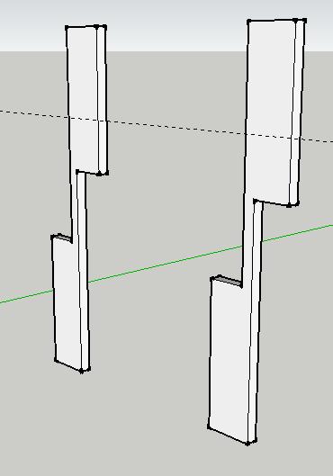
21 34. Using the Move tool and Ctrl key, make a copy of the small building, placing it in front of the big building. 35. Now select the Rotate tool from the toolbar. 36. Put the cursor over the endpoint on the front bottom corner of the new small building (No.1). You will see a blue protractor (it MUST be the blue one). Then click on the far corner (No. 2). This sets the axis for you to move the building around By moving your cursor, swing the building around until it shows a dotted line with a prompt that tells you it is on the green axis. Alternatively, once you have started to move it just type 90 and press Enter. The small building is now at a right angle to the big one. 21


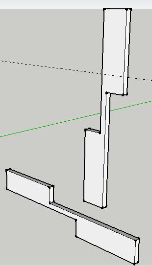
22 38. Orientate the drawing so you can see the far end of the big building and then use the Move tool to bring the small building in line with it (look for the purple dot and the prompt again). Click to set it in place. 39. Orientate your drawing again so you can see the far small building. 40. Use the Rotate tool to turn it through 90 degrees, as before. 22


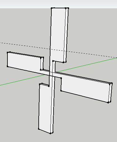
23 41. Once you have rotated the small building, orientate your drawing to view the back of the large one. 42. Then use the Move tool to bring the small building in line with the big one. 43. With the small building selected, go to the menu bar and from the Tools drop-down menu select Scale once again. 44. Use your judgement to stretch the building from the corner node so it looks like the one below. 23

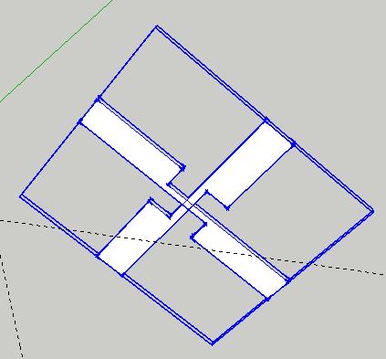
24 By now the building is pretty complex as it is made up of several components put together. At this point we need to make it possible to draw details onto it and add colour later. 45. To do this, select and highlight one of the components. I have selected the one we have just been working on. Right-click to get a popup menu. 46. From this select Explode. Do this for each of the other components (except the original big building). Now the building is ready for you to put details on such as doors and windows, but first I am going to tell you how to make flat roofs for your designs (if you want them). 24


25 2. Flat-roof Buildings Note: I am showing this on a new drawing. 1. Use the Rectangle tool to make a 3000,3000 mm square as a base 2. Use the Push/Pull tool to extrude the square upwards by 3,000 mm. 3. Use the Line tool to draw a line going down at an angle from the top corner of the block (watch for the green dot to start from the Endpoint ) to the front edge (look for the red dot and On Edge ). 25


26 4. With the Push/Pull tool selected, hover the cursor over the triangle that you have formed. It will highlight in a light blue shade. 5. Drag the cursor along and it will take out material. Stop when the prompt On Face appears. This will leave the block with a sloping roof. 6. This makes a building, such as a shed, with a flat/sloping roof which can be on its own or to act a component when added to other building designs. 26


27 3. Adding Doors and Windows It is easy to add details such as doors and windows using the Rectangle or Line tools. However, these can look random if not planned out properly. It is best to create a simple grid pattern on the building and use it to put in these details. 1. Select the Tape Measure tool from the toolbar. 2. Click on the bottom edge of the wall as shown at No. 1 (look for the red dot) and then drag the mouse upwards. 2 You will see it pulling up a guideline. Stop when the prompt shows about 750 mm or just type in 750 to set the height Do the same again three more times, setting the heights at 2,200 another at 2,800, and another at 4,200. The gridlines will appear like this. 27


28 4. Use the Tape Measure tool again to set out some vertical guidelines. You can pull them out from this edge. 5. Use the Rectangle tool to draw in the windows using the grid pattern of guidelines that you have set up. When starting and finishing the rectangle, look for the little red cross and the Intersection prompt. 6. Do the same for all doors and windows on all the buildings walls. When you have finished, delete the guidelines using the Eraser tool. 28


29 4. Applying a Sketch Effect Having added the door and window details, etc. and deleting the guidelines, your drawing may look something like this. It just needs finishing off with colour and texture. However, while it is still a white building, try this out 1. From the menu bar select Window and then Styles. 2. In the pop-up window select Sketchy Edges from this pulldown menu. 3. From the following menu select Pen Black. 29


30 It instantly looks like a sketched drawing done by hand! 4. To set it back to the proper drawing, go back into Window and then Styles and select In Model from the drop-down menu. 5. From the next pop-up select the Architectural Design Style from the palette and this will reset the drawing. 30


31 5. Colour and Texture Rendering Having returned to the standard architectural view, you are going to colour and render your building. 1. Firstly select the Paint Bucket tool from the menu bar. 2. This pop-up window will appear. In the pull-down menu select Materials and then Brick and Cladding. 3. From the next window, simply select the kind of finish you would like for your building. 31


32 4. With the Paint Bucket tool selected, simply click on the area of the building that you would like to have that texture or colour. 5. Here is the building with the added brick texture. 6. Here it is with roofing shingles added. 7. Here it is with translucent glass windows, a wooden garage door and red doors. Note: If you find the rendering is not only applying to the part that you want you will need to right click on the object and select Edit Component first. 32

33 6. Resizing the Building So far all the design work has involved entering numbers to ensure that we are drawing to full scale. However, sometimes you may have just guessed the scale and proportions and at the end wish you had used real measurements. Using the following method, it is possible to convert a non-scaled drawing to something close to a scaled one. In this example it is easy to see that the house is not accurately to scale. You can see this by looking at the size of the person to the front door. Here is how to quickly and easily resize the whole drawing to make it to scale Before you start, you need to know the real size of one dimension. I happen to know that the height of a front door is 2,100 mm. 33
 and then click on the top corner of the door above it (No. 2).")

34 1. Select the Tape Measure tool from the toolbar Click on a bottom corner of the door (No. 1) and then click on the top corner of the door above it (No. 2). A prompt showing its drawn size will appear (1,500 mm in my case). 3. Then just type the real size and press Enter. I have put the real size of the door as A pop-up window will appear asking if you want to resize the model. Click on Yes and the whole drawing will instantly resize to a more realistic scale. 34


35 Here is the rescaled drawing all ready for adding colour and texture. And here is the same drawing when it has been rendered (coloured and textured). 35


36 7. Creating Round Structures Producing a basic round object is easy. Here is one example of how to go about this. 1. Select the Circle tool from the toolbar. Click on an area of the floor some way away from the Gelf (person). 2. Use the mouse to drag out a larger circle. Type 3000 and press Enter to get a scaled circle. The circle will automatically fill in with grey, ready to be extruded. 36


37 3. Use the Push/Pull tool to extrude the circle upwards. Type 1500 and press the Enter key to get a height of 1,500 mm. 4. Orbit your cylinder so that you get a better view of the top. 5. Select the Line tool. Now, find the centre of the top circle (blue dot and Centre prompt box) and click on it to start a radius. The centre can be tricky to find but it helps if you hover the cursor over the edge of the circle at first. 6. With the centre located, draw a line to meet the outside edge of the circle. It is all the better if this meets a Midpoint. Press the Esc button to make the line let go. 37


. The shape should fill in with grey.")
38 7. Using the Line tool again, draw a vertical line, making sure it is going in the blue axis. Use your judgement to make it the same length as this. Click to set the line in place. This next bit can be trickier than it looks as it is easy to mistakenly draw in the wrong axis. 8. Draw a short line parallel to the radius as shown. 9. Complete the shape by drawing another line to the meeting point of the radius and the circles edge. (look for the green Endpoint dot). The shape should fill in with grey. If it does not then you have drawn the shape incorrectly and will need to go back a few steps to try again. 38

39 For the next bit you will need the Large Tool Set. If it is not shown on the left-hand side of your screen as a column of icons then you can get it from the main toolbar under View, then Toolbars and then select Large Tool Set. Now select the Follow Me tool. 39


40 9. With the Follow Me tool selected, firstly click on the shape you have just made. It will highlight in a light blue. Then put the cursor over the top edge of the circle; it will highlight in red. This next bit is tricky but comes with practice 10. Starting close to the shape where it meets the edge, GENTLY move the cursor around the rim following the whole circumference. This will drag the shape around until you get back to the starting point (look for the Endpoint prompt). 11. When you get to the Endpoint, click to complete the action. It will then colour like the rest of the object. 40


41 8. Assembling Components With my round base completed, I have made it into a component (see previous) and started to draw a new building which I will add to it. I have modified the second building by putting a pitched roof on it. I have also made this into a component. To put this new component on top of the round base can be tricky and you need to quickly switch views. If you have not already got the Views toolbar, on the menu bar go on Views, then Toolbars and then select Views. 41


42 1. Select the house component to highlight it. 2. Using the Move tool, click on the front right corner (look for the purple dot and the prompt Endpoint ) and, with the mouse button pressed down, move the house upwards following the blue axis (if you can it sometimes helps to press the shift button while doing this). 3. Now select the Front view from the Views toolbar to check if the house is at the right height yet. 42


43 4. While in this Front view, use the Move tool again to centralise the house over the base. (I have moved the house along the red axis.) 5. Switching to a Right side view, you can see the house is not centred over the base. Use the Move tool to centre it. 43


44 6. Switch to the Top view to get a bird s-eye view of the two components. Is the house centred over the base? 7. Keep changing the view until you re sure that the house is properly lined up with the base. I can now start adding details to the construction. I can start to turn this drawing into a post-type windmill. 44


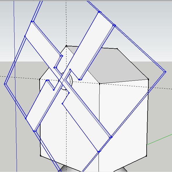
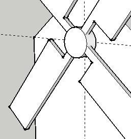
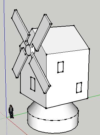
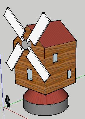
45 9. Windmill Sequence The next few pages show that sequence I used to construct a windmill. They use all the skills and tools that have been shown throughout this tutorial. See if you can work out what they are and try making your own. 45
46 46
47 47

48 48


49 10. Drawing Round Towers Several types of building can be defined as being towers, including lighthouses and some types of windmill. The following tutorials show you how to start the construction of such buildings. 1. Start by drawing a 2,500 mm radius circle on the floor. 2. Extrude it to a height of 12,000 mm. 49


50 3. Use the Select tool to highlight JUST the top of the column. 4. From the menu bar select Tools and from the drop-down menu select Scale. The top of the column will now have a yellow square around it with green nodes on it. 50

. 7. Press the Esc key to set the tapering column. 8.")
51 5. Put your cursor over a corner node and click to select it. 6. Press the Ctrl key down and at the same time use the mouse to gently drag the cursor towards the circle s centre. Because you have used the Ctrl key it will make the circle smaller about its centre. You can type a value for a precise scaling. I typed.6 (point six). 7. Press the Esc key to set the tapering column. 8. Using the Circle tool, click on the centre of the top of the column. 9. Drag out a circle and make it a 2,500 mm radius. 51


52 10. Use the Push/Pull tool to extrude the top by 1,500 mm. This may require you to separately extrude the inner and outer circles that make the top. 11. Push/Pull the inner circle up a further 3000 mm. 12. Use the Circle tool to put another 2,500 mm circle centrally on the top. 13. Extrude the top circles by 500 mm and then use the Eraser tool to delete the inner circle. 52


53 The next sequence is very similar to the construction of the round structures that we covered earlier. 14. Use the Line tool to draw a radius. 15. Now draw a vertical line (in the blue axis) about 1,500 mm high. 16. Use the Line tool to complete the triangle. 53


54 17. Use the Follow Me tool to revolve the triangle about its central axis. This makes a cap for the top. This makes a good start to a lighthouse but the same techniques can be used for other structures. 54
 2.")
55 11. Drawing Polygonal Towers This follows a very similar sequence to the previous lighthouse structure with a few minor differences. 1. From the Large Tool Set to the left of your screen, select the Polygon tool. (Refer to the Round Structures section if you don t have one.) 2. Place the cursor over an area on the floor a distance away from the axis origin as shown, but don t click to set it in place yet. 3. Instead type 8. This will set the number of sides your polygon is going to have. 55


56 4. Now click and drag the mouse to pull out the octagon shape. You can, of course, set the size now by typing Use the Push/Pull tool to extrude by 12,000 mm. 6. Use the Select tool to highlight just the top octagon. 56


57 7. From the menu bar select Tools and from the drop-down menu select Scale. A yellow box with green nodes will appear. 8. Put your cursor over a corner node and click to select it. 9. Press the Ctrl key down and at the same time use the mouse to gently drag the cursor towards the circle s centre. Press the Esc key to deselect. This next part is slightly different from the previous example. 10. From the toolbar select the Offset tool. 11. As you place your cursor over the top octagon it will highlight. Click on it and drag it out a small way before clicking to set it. 57


58 12. Use the Push/Pull tool to extrude the top octagons by 2,000 mm. 13. Then use the line tool to draw from the octagon s centre to one of its corners. 14. As in the last exercise, use the line tool to form a triangle, making sure all the Endpoints meet. 58


59 15. Use the line tool again to join the top of the triangle to each corner. As you do each one, they will fill in to create a roof. Here is the completed roof. And here is how the whole polygonal tower looks. The same techniques could be used to make all types of building structure. 59


60 On this example I have cut, pasted and rescaled the sails from my earlier windmill drawing. Here is a finished, rendered version of the octagonal windmill. 60
61 12. Creating Stairs Method 1 Subdivided Rectangles The simplest way to draw a staircase is to firstly draw a rectangle, divide it up and extrude each division to form individual steps. You will need to know how many steps you are going to use and the height of the steps in total. Follow this example to see how 1. Once you have opened Google SketchUp, go to Window and select Preferences. 2. Select Template and choose Architectural Design Millimetres. You are using this template because you are doing an architectural project. Click on OK. Note: It is often necessary to start a new file for the new template to load. Go to File then New. 61


62 3. Now select the Rectangle tool and draw a rectangle on the floor by clicking and dragging the cursor across diagonally. 4. Now type 1500,1500 to set the size of the rectangle you have drawn. At this point it is worth zooming in to the rectangle. 5. Use the Pick tool to select the side edge of the rectangle. 6. From the pop-up box click on Divide and type 5, and then press Enter. You will see a series of four construction points appear on the blue highlighted line, dividing it into five equal pieces. 62


. 10.")
63 7. Press the Esc key or click into a space to deselect the highlighted line. 8. Select the Line tool and click on the first of the construction points (look for the green dot and the Endpoint prompt. 9. Draw a line in the red axis, parallel to the front edge, all the way across the rectangle (look for the red dot and the prompt On Edge ). 10. Do the same for the other construction points to divide the rectangle into five pieces. 63


64 11. Use the Line tool again to draw a vertical line from a corner in the blue axis. 12. Type 1000 to make it the height that you want the total height of the stairs to be. Press the Esc key to let go of the line. 13. Use the Pick tool to select the vertical line, then right-click the mouse button. On the pop-up box, click on Divide and type 4. The line will now show three construction points that divide it into four equal pieces. 64


65 14. Select the Push/Pull tool and extrude the last step. Make it equal to the height of the vertical line you have drawn by bringing the cursor over its last construction point (look for the green dot and the Endpoint prompt). 15. Then use the Push/Pull tool again to extrude the next-to-last step level with the next construction point down the vertical line. 65


66 16. Do the same for the rest of the steps until you have a complete set. 17. Now you can delete any unnecessary lines using the Erase tool. This completes Method One. 66

. Then move the cursor along the front edge (see No. 2) tracing a line over it.")
67 Method 2 The Profile Method 1. To start the profile method, firstly draw a 1,500, 1,500 square and then extrude it to a height of 1,000 mm to make a block like this one. 2. Select the Line tool and start a line by clicking on the bottom corner of the front edge (see No. 1). Then move the cursor along the front edge (see No. 2) tracing a line over it. 2 With the cursor hovering over the front edge, type 250 and then press the Enter key. This will create a construction point. 1 67
. Drag the line out across the front face in green axis (it will show as a green line). Type 300 to set its length.")

68 3. Using the Line tool again, draw a horizontal line by starting it on the new construction line (look for the green dot and Endpoint prompt). Drag the line out across the front face in green axis (it will show as a green line). Type 300 to set its length. The line will now turn black. Press Esc to let go of the line. 4. Now use the Pick tool to firstly select the new horizontal line and then, by keeping the Shift key pressed down, select the short vertical line that attaches to it on the front edge. Both lines should now be highlighted. 68
 on it to show it is now a Copy tool. 1 6.")

69 5. With the two lines highlighted, select the Move tool from the toolbar. Then press the Ctrl key once. The cursor will now have a tiny plus sign (+) on it to show it is now a Copy tool Now click the cursor on the bottom of the small vertical line (No. 1; look for the Endpoint prompt). This selects and copies the two lines. 7. Move the selected lines, placing the copy at the end of the horizontal line (look for green dot and Endpoint prompt). 69


70 8. Follow this procedure two more times so that your lines become level with the top of the block. 9. Select the Push/Pull tool and hover the cursor over the profile of the stairs. Note the stair shape highlights in pale blue. 10. Extrude the stair profile by dragging it out with the mouse. Type 1500 and Enter to set the width. This completes Method Two. 70


71 Method 3 Using Components 1. Firstly, delete the Gelf person using the Erase tool (or just hit the Del key) as she will only get in the way on this example. 2. Using the Rectangle tool, draw a rectangle on the floor. 71


72 3. As soon as you have drawn the rectangle, type 1500,300 to set the size of the stair tread. 4. Using the Push/Pull tool, extrude the rectangle upwards and type 250 to set the height of the stairs riser. This block represents a single step that is 250 mm high, 300 mm deep and 1,500 mm wide. 5. Triple-click or use the Pick tool to select the whole block by drawing a box around it. It will highlight in blue. 72


73 6. With the block highlighted, right-click your mouse to bring up this pop-up box. From the list select Make Component. This new dialog box will appear. 7. Give the component a name. I have called mine Tread. Then click on Create to make the tread component. 73
 on it to show it is now a Copy tool. 9.")

.")
74 8. Select the Move tool and change it into a Copy tool by pressing the Ctrl key. The cursor will now have a tiny plus sign (+) on it to show it is now a Copy tool. 9. Now click on the bottom corner of the block looking for the purple dot and the Endpoint in Component prompt. 10. Drag and place the copied component so that it joins to the original component s top corner (look for the purple dot and the Endpoint in Component prompt). Now type 4x and the step will be copied four more times. Note: Each step is an instance of the same component. If you change one, the others will change too. 74


75 9. Use the Pick tool to select any one of the stairs. It will highlight in blue. 10. Now right-click on it to bring up a pop-up box. From the list select Edit Component. 11. An editing box will appear around it. This enables you to change the component. 75


76 12. Orbit the stairs so that you can see the underside. (Press down the middle mouse wheel and move it.) You may also wish to zoom in at this point. (Roll the middle mouse wheel to zoom.) 13. With the Push/Pull tool selected, push the underside of the chosen step upwards to reduce its thickness. Notice how all the other copies change at the same time! Push up 76


77 14. Orbit the stairs again and use the Push/Pull tool to extrude the front edge of the selected step by 50 mm. This makes the steps overlap realistically by giving each step a nosing. You can see that anything you do to one step makes the same changes on the others. A worked example follows, but you should experiment to develop your own staircase details. 15. On the step to be edited I have drawn a 25 mm radius circle using the Circle tool. Note that similar circles appear on each of the other steps. 77

 to the centre of the adjacent balustrade top (No. 2). 1 18.")

78 16. Using the Push/Pull tool, extrude the circle to a height of 900 mm to create the balustrades. Again the other circles will extrude Using the Line tool, draw a line to connect the centre of the circle at the top of the balustrade (No. 1) to the centre of the adjacent balustrade top (No. 2) Select the Follow Me tool from the large tool set. If you do not have this already on your screen on the taskbar, go to View > Toolbars > Large Tool Set to get it. Hover the mouse over the top circle of your balustrade and it will highlight in light blue. 78


79 19. With the Follow Me tool selected, click on the highlighted circle and keep the mouse button pressed down. 20. Drag the circle along the length of the line you drew to connect it to the next balustrade. Do this slowly and carefully, watching that the line is coloured red while you do it. 21. When you have dragged the circle to the middle of the top of the next balustrade, release the mouse button. The other stair components will have joined up to give you a complete handrail. 79


80 22. The bottom end of the handrail will look a bit unfinished, so select the Push/Pull tool to extrude it out beyond the first balustrade. 23. Now that you have finished editing the component, right-click the mouse over it and a pop-up box will appear. Click on Close Component to finish. Note: I could have chosen the bottom step to edit, which may have been a bit more elegant, but the end result is the same. 80
Photocopiable/digital resources may only be copied by the purchasing institution on a single site and for their own use ZigZag Education, 2013
 SketchUp Level of Difficulty Time Approximately 15 20 minutes Photocopiable/digital resources may only be copied by the purchasing institution on a single site and for their own use ZigZag Education, 2013
SketchUp Starting Up The first thing you must do is select a template.
 SketchUp Starting Up The first thing you must do is select a template. While there are many different ones to choose from the only real difference in them is that some have a coloured floor and a horizon
CAD Tutorial 23: Exploded View
 CAD TUTORIAL 23: Exploded View CAD Tutorial 23: Exploded View Level of Difficulty Time Approximately 30 35 minutes Starter Activity It s a Race!!! Who can build a Cube the quickest: - Pupils out of Card?
SketchUp. SketchUp. Google SketchUp. Using SketchUp. The Tool Set
 Google Google is a 3D Modelling program which specialises in making computer generated representations of real-world objects, especially architectural, mechanical and building components, such as windows,
SketchUp Quick Start For Surveyors
 SketchUp Quick Start For Surveyors Reason why we are doing this SketchUp allows surveyors to draw buildings very quickly. It allows you to locate them in a plan of the area. It allows you to show the relationship
The Villa Savoye ( ), Poisy, Paris.
, Poisy, Paris.") Learning SketchUp Villa Savoye This tutorial will involve modeling the Villa Savoye by Le Corbusier Files needed to complete this tutorial are available in Mr. Cochran s Web Site The Villa Savoye (1929-1931),
Learning SketchUp Villa Savoye This tutorial will involve modeling the Villa Savoye by Le Corbusier Files needed to complete this tutorial are available in Mr. Cochran s Web Site The Villa Savoye (1929-1931),
Beaumont Middle School Design Project April May 2014 Carl Lee and Craig Schroeder
 Beaumont Middle School Design Project April May 2014 Carl Lee and Craig Schroeder 1 2 SketchUp 1. SketchUp is free, and you can download it from the website www.sketchup.com. For some K12 use, see www.sketchup.com/3dfor/k12-education.
Google SketchUp. and SketchUp Pro 7. The book you need to succeed! CD-ROM Included! Kelly L. Murdock. Master SketchUp Pro 7 s tools and features
 CD-ROM Included! Free version of Google SketchUp 7 Trial version of Google SketchUp Pro 7 Chapter example files from the book Kelly L. Murdock Google SketchUp and SketchUp Pro 7 Master SketchUp Pro 7 s
SolidWorks Intro Part 1b
 SolidWorks Intro Part 1b Dave Touretzky and Susan Finger 1. Create a new part We ll create a CAD model of the 2 ½ D key fob below to make on the laser cutter. Select File New Templates IPSpart If the SolidWorks
SolidWorks 2½D Parts
 SolidWorks 2½D Parts IDeATe Laser Micro Part 1b Dave Touretzky and Susan Finger 1. Create a new part In this lab, you ll create a CAD model of the 2 ½ D key fob below to make on the laser cutter. Select
Tutorial 3: Constructive Editing (2D-CAD)
") (2D-CAD) The editing done up to now is not much different from the normal drawing board techniques. This section deals with commands to copy items we have already drawn, to move them and to make multiple
(2D-CAD) The editing done up to now is not much different from the normal drawing board techniques. This section deals with commands to copy items we have already drawn, to move them and to make multiple
SketchUp + Google Earth LEARNING GUIDE by Jordan Martin. Source (images): Architecture
: Architecture") SketchUp + Google Earth LEARNING GUIDE by Jordan Martin Source (images): www.sketchup.com Part 1: Getting Started with SketchUp GETTING STARTED: Throughout this manual users will learn different tools
SketchUp + Google Earth LEARNING GUIDE by Jordan Martin Source (images): www.sketchup.com Part 1: Getting Started with SketchUp GETTING STARTED: Throughout this manual users will learn different tools
Using Google SketchUp
 Using Google SketchUp Mike Bailey mjb@cs.oregonstate.edu http://cs.oregonstate.edu/~mjb/sketchup What is Google SketchUp? Google SketchUp is a program which lets you sketch in 3D. It is excellent for creating
Firstly, I would like to thank ProFantasy for hosting this tutorial on the RPGMaps Blog. Thank you!
 Firstly, I would like to thank ProFantasy for hosting this tutorial on the RPGMaps Blog. Thank you! Before we start, it is important that you fully understand what a shaded polygon is, and what it does.
Introduction to Google SketchUp
 Introduction to Google SketchUp When initially opening SketchUp, it will be useful to select the Google Earth Modelling Meters option from the initial menu. If this menu doesn t appear, the same option
Getting Started. Moving Around in 3D
 Getting Started 1 Double-click the SketchUp icon or click: Start All Programs SketchUp 2018 SketchUp 2018 The start screen should look something like this: This person is about 5 5 tall this sets the scale
Getting Started. Double-click the SketchUp icon or click: Start All Programs SketchUp 2018 SketchUp 2018
 Getting Started 1 Double-click the SketchUp icon or click: Start All Programs SketchUp 2018 SketchUp 2018 The start screen should look something like this: This person is about 5 5 tall this sets the scale
Using Google SketchUp
 Using Google SketchUp Mike Bailey mjb@cs.oregonstate.edu http://cs.oregonstate.edu/~mjb/sketchup What is Google SketchUp? Google SketchUp is a program which lets you sketch in 3D. It is excellent for creating
A Guide to Autodesk Maya 2015
 A Guide to Autodesk Maya 2015 Written by Mitchell Youngerman Table of Contents Layout of Toolbars...pg 1 Creating Objects...pg 2 Selecting & Deselecting Objects...pg 3 Changing Perspective... pg 4 Transforming
SOLIDWORKS: Lesson 1 - Basics and Modeling. Introduction to Robotics
 SOLIDWORKS: Lesson 1 - Basics and Modeling Fundamentals Introduction to Robotics SolidWorks SolidWorks is a 3D solid modeling package which allows users to develop full solid models in a simulated environment
3D Design with 123D Design
 3D Design with 123D Design Introduction: 3D Design involves thinking and creating in 3 dimensions. x, y and z axis Working with 123D Design 123D Design is a 3D design software package from Autodesk. A
Dice in Google SketchUp
 A die (the singular of dice) looks so simple. But if you want the holes placed exactly and consistently, you need to create some extra geometry to use as guides. Plus, using components for the holes is
Lesson 1 Parametric Modeling Fundamentals
 1-1 Lesson 1 Parametric Modeling Fundamentals Create Simple Parametric Models. Understand the Basic Parametric Modeling Process. Create and Profile Rough Sketches. Understand the "Shape before size" approach.
SketchUp Tool Basics
 SketchUp Tool Basics Open SketchUp Click the Start Button Click All Programs Open SketchUp Scroll Down to the SketchUp 2013 folder Click on the folder to open. Click on SketchUp. Set Up SketchUp (look
GETTING STARTED WITH SKETCHUP
 MENUS TOOLBARS GETTING STARTED WITH SKETCHUP When opening a new document the image will likely look like this. Familiarize yourself with the options available in the program. Additional toolbars can be
Introduction to SolidWorks Basics Materials Tech. Wood
 Introduction to SolidWorks Basics Materials Tech. Wood Table of Contents Table of Contents... 1 Book End... 2 Introduction... 2 Learning Intentions... 2 Modelling the Base... 3 Modelling the Front... 10
Google SketchUp Design Exercise 1
 Google SketchUp Design Exercise 1 The first thing students like to do in SketchUp is make a basic house and try out different colors and materials. They also love making windows and doors, and trying out
Modeling a Gear Standard Tools, Surface Tools Solid Tool View, Trackball, Show-Hide Snaps Window 1-1
 Modeling a Gear This tutorial describes how to create a toothed gear. It combines using wireframe, solid, and surface modeling together to create a part. The model was created in standard units. To begin,
TUTORIAL No 1: Page Setup
 TUTORIAL No 1: Page Setup Skill Level: Foundation This tutorial shows you how to set up a workspace to draw in. The workspace is the area you are working in on the screen. 1. Open 2D Design. A screen with
Lesson for levels K-5 Time to complete: min
 Lesson Plan: Lesson for levels K-5 Time to complete: 45-90 min Lesson Plan: Level: Grades K-5 (ages 5-10) Time to complete: ~45-90 minutes Learn how to build basic geometry, apply materials, and import
Luana Valentini InternetGIS course
 Google SketchUp - A brief introduction - Luana Valentini InternetGIS course - 2011 Create 3D models and share them with the world Google SketchUp is software that allows you to create 3D models of anything
Digital City: Introduction to 3D modeling
 Digital City: Introduction to 3D modeling Weixuan Li, 2017 PART I: Install SketchUp and Introduction 1. Download SketchUp Download SketchUp from their official website: https://www.sketchup.com Go to the
3D Digital Design. SketchUp
 3D Digital Design SketchUp 1 Overview of 3D Digital Design Skills A few basic skills in a design program will go a long way: 1. Orien
Parametric Modeling. With. Autodesk Inventor. Randy H. Shih. Oregon Institute of Technology SDC PUBLICATIONS
 Parametric Modeling With Autodesk Inventor R10 Randy H. Shih Oregon Institute of Technology SDC PUBLICATIONS Schroff Development Corporation www.schroff.com www.schroff-europe.com 2-1 Chapter 2 Parametric
3ds Max Cottage Step 1. Always start out by setting up units: We re going with this setup as we will round everything off to one inch.
 3ds Max Cottage Step 1 Always start out by setting up units: We re going with this setup as we will round everything off to one inch. File/Import the CAD drawing Be sure Files of Type is set to all formats
Adobe Flash CS3 Reference Flash CS3 Application Window
 Adobe Flash CS3 Reference Flash CS3 Application Window When you load up Flash CS3 and choose to create a new Flash document, the application window should look something like the screenshot below. Layers
Introduction to SolidWorks for Technology. No1: Childs Toy
 Introduction to SolidWorks for Technology No1: Childs Toy Table of Contents Table of Contents... 1 Introduction... 2 Part Modelling: Cab... 3 Part Modelling: Base... 6 Part Modelling: Wheel... 12 Assembly:
SWITCHING FROM SKETCHUP TO VECTORWORKS
 SWITCHING FROM SKETCHUP TO VECTORWORKS INTRODUCTION There are a lot of 3D modeling software programs to choose from and each has its own strengths and weaknesses. For architects, flexibility and ease of
lundi 7 janvier 2002 Blender: tutorial: Building a Castle Page: 1
 lundi 7 janvier 2002 Blender: tutorial: Building a Castle Page: 1 www.blender.nl this document is online at http://www.blender.nl/showitem.php?id=4 Building a Castle 2000 07 19 Bart Veldhuizen id4 Introduction
SOLIDWORKS: Lesson III Patterns & Mirrors. UCF Engineering
 SOLIDWORKS: Lesson III Patterns & Mirrors UCF Engineering Solidworks Review Last lesson we discussed several more features that can be added to models in order to increase their complexity. We are now
User Guide. for. JewelCAD Professional Version 2.0
 User Guide Page 1 of 121 User Guide for JewelCAD Professional Version 2.0-1 - User Guide Page 2 of 121 Table of Content 1. Introduction... 7 1.1. Purpose of this document... 7 2. Launch JewelCAD Professional
Tutorial 2: Particles convected with the flow along a curved pipe.
 Tutorial 2: Particles convected with the flow along a curved pipe. Part 1: Creating an elbow In part 1 of this tutorial, you will create a model of a 90 elbow featuring a long horizontal inlet and a short
Introduction To Inkscape Creating Custom Graphics For Websites, Displays & Lessons
 Introduction To Inkscape Creating Custom Graphics For Websites, Displays & Lessons The Inkscape Program Inkscape is a free, but very powerful vector graphics program. Available for all computer formats
How to...create a Video VBOX Gauge in Inkscape. So you want to create your own gauge? How about a transparent background for those text elements?
 BASIC GAUGE CREATION The Video VBox setup software is capable of using many different image formats for gauge backgrounds, static images, or logos, including Bitmaps, JPEGs, or PNG s. When the software
Module 4A: Creating the 3D Model of Right and Oblique Pyramids
 Inventor (5) Module 4A: 4A- 1 Module 4A: Creating the 3D Model of Right and Oblique Pyramids In Module 4A, we will learn how to create 3D solid models of right-axis and oblique-axis pyramid (regular or
Autodesk Inventor Design Exercise 2: F1 Team Challenge Car Developed by Tim Varner Synergis Technologies
 Autodesk Inventor Design Exercise 2: F1 Team Challenge Car Developed by Tim Varner Synergis Technologies Tim Varner - 2004 The Inventor User Interface Command Panel Lists the commands that are currently
How to Make a Sign. Eagle Plasma LLC. Accessing the included step by step.dxf files
 Eagle Plasma LLC How to Make a Sign Accessing the included step by step.dxf files The following tutorial is designed to teach beginners, screen by screen, to create a simple sign project. In this lesson
How to draw and create shapes
 Adobe Flash Professional Guide How to draw and create shapes You can add artwork to your Adobe Flash Professional documents in two ways: You can import images or draw original artwork in Flash by using
Graphic Design & Digital Photography. Photoshop Basics: Working With Selection.
 1 Graphic Design & Digital Photography Photoshop Basics: Working With Selection. What You ll Learn: Make specific areas of an image active using selection tools, reposition a selection marquee, move and
Creating Vector Shapes Week 2 Assignment 1. Illustrator Defaults
 Illustrator Defaults Before we begin, we are going to make sure that all of us are using the same settings within our application. For this class, we will always want to make sure that our application
SketchUp Help. 1 of 15 8/29/09 10:00 AM
 SketchUp Help Creating your first model It will take some time to master SketchUp as with any new software. However, following is a project to help you better learn the tools and concepts covered in this
AUTODESK FUSION 360 Designing a RC Car Body
 AUTODESK FUSION 360 Designing a RC Car Body Abstract This project explores how to use the sculpting tools available in Autodesk Fusion 360 Ultimate to design the body of a RC car. John Helfen john.helfen@autodesk.com
Vectorworks Essential Tutorial Manual by Jonathan Pickup. Sample
 Vectorworks Essential Tutorial Manual by Jonathan Pickup Table of Contents 0.0 Introduction... iii 0.1 How to Use this Manual... iv 0.2 Real World Sizes... iv 0.3 New Ways of Drawing... v 1.0 Introduction
Tutorial 1 Engraved Brass Plate R
 Getting Started With Tutorial 1 Engraved Brass Plate R4-090123 Table of Contents What is V-Carving?... 2 What the software allows you to do... 3 What file formats can be used?... 3 Getting Help... 3 Overview
The Rectangular Problem
 C h a p t e r 2 The Rectangular Problem In this chapter, you will cover the following to World Class standards: The tools for simple 2D Computer Aided Drafting (CAD) The Command Line and the Tray The Line
Revit Architecture 2015 Basics
 Revit Architecture 2015 Basics From the Ground Up Elise Moss Authorized Author SDC P U B L I C AT I O N S Better Textbooks. Lower Prices. www.sdcpublications.com Powered by TCPDF (www.tcpdf.org) Visit
WAYLAND FREE PUBLIC LIBRARY 3D Design and Printing Tutorial: Create a Keychain
 WAYLAND FREE PUBLIC LIBRARY 3D Design and Printing Tutorial: Create a Keychain Welcome! In this tutorial we will be creating a 3D printed keychain. You will personalize this name tag with text to make
A Quick Spin on Autodesk Architectural Studio
 December 2-5, 2003 MGM Grand Hotel Las Vegas A Quick Spin on Autodesk Architectural Studio Mario Guttman, AIA Kevin Durham Christie Landry (Instructor) (Assistant) (Assistant) BD13-5L Autodesk Architectural
This is the opening view of blender.
 This is the opening view of blender. Note that interacting with Blender is a little different from other programs that you may be used to. For example, left clicking won t select objects on the scene,
Designer Reference 1
 Designer Reference 1 Table of Contents USE OF THE DESIGNER...4 KEYBOARD SHORTCUTS...5 Shortcuts...5 Keyboard Hints...5 MENUS...7 File Menu...7 Edit Menu...8 Favorites Menu...9 Document Menu...10 Item Menu...12
Autodesk Fusion 360: Model. Overview. Modeling techniques in Fusion 360
 Overview Modeling techniques in Fusion 360 Modeling in Fusion 360 is quite a different experience from how you would model in conventional history-based CAD software. Some users have expressed that it
Fireplace Mantel in Google SketchUp
 Creating the fireplace itself is quite easy: it s just a box with a hole. But creating the mantel around the top requires the fun-to-use Follow Me tool. This project was created in SketchUp 8, but will
MAKING A TRIPTYCH IN PHOTOSHOP CC
 MAKING A TRIPTYCH IN PHOTOSHOP CC Open Photoshop CC and create a New Document Remember, the images shown here are 'screen grabs from my computer. I am using Photoshop CC. Therefore your screen may look
Modeling a Fluted Column in Google SketchUp
 Architectural columns in ancient Greece, Rome, and even China used flutes - vertical grooves cut along the outside of the cylinder. If you want to create a model of an ancient temple, or perhaps one of
EDITING SHAPES. Lesson overview
 3 CREATING AND EDITING SHAPES Lesson overview In this lesson, you ll learn how to do the following: Create a document with multiple artboards. Use tools and commands to create basic shapes. Work with drawing
Exercise Guide. Published: August MecSoft Corpotation
 VisualCAD Exercise Guide Published: August 2018 MecSoft Corpotation Copyright 1998-2018 VisualCAD 2018 Exercise Guide by Mecsoft Corporation User Notes: Contents 2 Table of Contents About this Guide 4
Spira Mirabilis. Finding the Spiral tool. Your first spiral
 Spira Mirabilis Finding the Spiral tool The Spiral tool is part of ShapeWizards suite called MagicBox (the other tools in the suite are Pursuit, Shell, Sphere). You can install all these tools at once
CS Multimedia and Communications REMEMBER TO BRING YOUR MEMORY STICK TO EVERY LAB! Lab 02: Introduction to Photoshop Part 1
 CS 1033 Multimedia and Communications REMEMBER TO BRING YOUR MEMORY STICK TO EVERY LAB! Lab 02: Introduction to Photoshop Part 1 Upon completion of this lab, you should be able to: Open, create new, save
Week 1 The Blender Interface and Basic Shapes
 Week 1 The Blender Interface and Basic Shapes Blender Blender is an open-source 3d software that we will use for this class to create our 3d game. Blender is as powerful as 3d Studio Max and Maya and has
Let s Make a Front Panel using FrontCAD
 Let s Make a Front Panel using FrontCAD By Jim Patchell FrontCad is meant to be a simple, easy to use CAD program for creating front panel designs and artwork. It is a free, open source program, with the
LESSON 2 MODELING BASICS
 LESSON 2 MODELING BASICS In this lesson we ll start to model a multi-story office building from scratch. We ll construct the base grid, create the two towers and place slabs between the stories. Also we
Esrefoglu Pattern, in Google SketchUp
 One of my favorite geometry books is Islamic Geometry Patterns by Eric Broug. The book contains instructions on 19 beautiful patterns found throughout the Middle East and Asia, and Eric s main tools are
Making an Aquarium in Google SketchUp
 Making an Aquarium in Google SketchUp If you are a decent 3D modeler, you could design an aquarium filled with 3D models of sea plants, coral, and fish. To save time, you could even find most of these
Paint Tutorial (Project #14a)
") Paint Tutorial (Project #14a) In order to learn all there is to know about this drawing program, go through the Microsoft Tutorial (below). (Do not save this to your folder.) Practice using the different
Paint Tutorial (Project #14a) In order to learn all there is to know about this drawing program, go through the Microsoft Tutorial (below). (Do not save this to your folder.) Practice using the different
Rhombic Hexacontahedron in Google SketchUp
 Check out this cool-looking shape: You can read more about it here: http://mathworld.wolfram.com/rhombichexecontahedron.html. It looks sort of complicated, and I ll admit it takes a number of steps to
Note: Photoshop tutorial is spread over two pages. Click on 2 (top or bottom) to go to the second page.
 to go to the second page.") Introduction During the course of this Photoshop tutorial we're going through 9 major steps to create a glass ball. The main goal of this tutorial is that you get an idea how to approach this. It's not
Introduction During the course of this Photoshop tutorial we're going through 9 major steps to create a glass ball. The main goal of this tutorial is that you get an idea how to approach this. It's not
Lesson 1: Creating T- Spline Forms. In Samples section of your Data Panel, browse to: Fusion 101 Training > 03 Sculpt > 03_Sculpting_Introduction.
 3.1: Sculpting Sculpting in Fusion 360 allows for the intuitive freeform creation of organic solid bodies and surfaces by leveraging the T- Splines technology. In the Sculpt Workspace, you can rapidly
Create an Adorable Hedgehog with Basic Tools in Inkscape Aaron Nieze on Sep 23rd 2013 with 5 Comments
 Create an Adorable Hedgehog with Basic Tools in Inkscape Aaron Nieze on Sep 23rd 2013 with 5 Comments Tutorial Details Software: Inkscape Difficulty: Beginner Completion Time: 2 hours View post on Tuts+
Creating a Poster in Google SketchUp
 If you have digital image, or can find one online, you can easily make that image into a room poster. For this project, it helps to have some basic knowledge of Google SketchUp (though detailed instructions
Blender Lesson Ceramic Bowl
 Blender Lesson Ceramic Bowl This lesson is going to show you how to create a ceramic looking bowl using the free program Blender. You will learn how to change the view, add, delete, scale and edit objects
Generating Vectors Overview
 Generating Vectors Overview Vectors are mathematically defined shapes consisting of a series of points (nodes), which are connected by lines, arcs or curves (spans) to form the overall shape. Vectors can
Spring 2011 Workshop ESSENTIALS OF 3D MODELING IN RHINOCEROS February 10 th 2011 S.R. Crown Hall Lower Core Computer Lab
 [1] Open Rhinoceros. PART 1 INTRODUCTION [4] Click and hold on the Boundary Lines in where they form a crossing and Drag from TOP RIGHT to BOTTOM LEFT to enable only the PERSPECTIVE VIEW. [2] When the
Autodesk Fusion 360 Training: The Future of Making Things Attendee Guide
 Autodesk Fusion 360 Training: The Future of Making Things Attendee Guide Abstract After completing this workshop, you will have a basic understanding of editing 3D models using Autodesk Fusion 360 TM to
Drawing Tools. Drawing a Rectangle
 Chapter Microsoft Word provides extensive DRAWING TOOLS that allow you to enhance the appearance of your documents. You can use these tools to assist in the creation of detailed publications, newsletters,
The Best of SketchUp This amazing 3D design program can make you a better woodworker.
 The Best of SketchUp This amazing 3D design program can make you a better woodworker. By David Heim More and more woodworkers have switched from T-square and pencil to the SketchUp 3D program to design
The Menger Sponge in Google SketchUp
 The Sierpinsky Carpet (shown below on the left) is a 2D fractal made from squares repeatedly divided into nine smaller squares. The Menger Sponge (shown below on the right) is the 3D version of this fractal.
Autodesk Inventor - Basics Tutorial Exercise 1
 Autodesk Inventor - Basics Tutorial Exercise 1 Launch Inventor Professional 2015 1. Start a New part. Depending on how Inventor was installed, using this icon may get you an Inch or Metric file. To be
Learning Microsoft Word By Greg Bowden. Chapter 10. Drawing Tools. Guided Computer Tutorials
 Learning Microsoft Word 2007 By Greg Bowden Chapter 10 Drawing Tools Guided Computer Tutorials www.gct.com.au PUBLISHED BY GUIDED COMPUTER TUTORIALS PO Box 311 Belmont, Victoria, 3216, Australia www.gct.com.au
FACULTY AND STAFF COMPUTER FOOTHILL-DE ANZA. Office Graphics
 FACULTY AND STAFF COMPUTER TRAINING @ FOOTHILL-DE ANZA Office 2001 Graphics Microsoft Clip Art Introduction Office 2001 wants to be the application that does everything, including Windows! When it comes
ELEC451 Integrated Circuit Engineering Using Cadence's Virtuoso Layout Editing Tool
 ELEC451 Integrated Circuit Engineering Using Cadence's Virtuoso Layout Editing Tool Contents Contents 1. General 2. Creating and Working On a Layout o 2.1 Undoing/Re-doing an Action o 2.2 Display Options
3D Modeler Creating Custom myhouse Symbols
 3D Modeler Creating Custom myhouse Symbols myhouse includes a large number of predrawn symbols. For most designs and floorplans, these should be sufficient. For plans that require that special table, bed,
PLAY VIDEO. Fences can be any shape from a simple rectangle to a multisided polygon, even a circle.
 Chapter Eight Groups PLAY VIDEO INTRODUCTION There will be times when you need to perform the same operation on several elements. Although this can be done by repeating the operation for each individual
Introduction Make a plan with tool Rectangle Measurements Toolbar Enter Return Measurements Toolbar Measure Protractor
 Introduction Open SketchUp, and an empty file appears. You are looking at the red-green plane, and the blue axis (vertical) is pointing toward you. By default, you are in the Line tool, as indicated by
GETTING STARTED TABLE OF CONTENTS
 Sketchup Tutorial GETTING STARTED Sketchup is a 3D modeling program that can be used to create 3D objects in a 2D environment. Whether you plan to model for 3D printing or for other purposes, Sketchup
1 General Principles. General Principles. In this chapter 1-1
 1 General Principles In this chapter 1 General Principles 1.1 User Interface 1.2 Title bar 1.3 Menu bar 1.4 Standard Toolbar 1.5 The drawing area 1.6 Component tabs 1.7 Status Bar 1.8 Manipulating Components
Quick Crash Scene Tutorial
 Quick Crash Scene Tutorial With Crash Zone or Crime Zone, even new users can create a quick crash scene diagram in less than 10 minutes! In this tutorial we ll show how to use Crash Zone s unique features
Profile Modeler Profile Modeler ( A SuperControl Product )
") Profile Modeler ( A SuperControl Product ) - 1 - Index Overview... 3 Terminology... 3 Launching the Application... 4 File Menu... 4 Loading a File:... 4 To Load Multiple Files:... 4 Clearing Loaded Files:...
Profile Modeler ( A SuperControl Product ) - 1 - Index Overview... 3 Terminology... 3 Launching the Application... 4 File Menu... 4 Loading a File:... 4 To Load Multiple Files:... 4 Clearing Loaded Files:...
Ancient Cell Phone Tracing an Object and Drawing with Layers
 Ancient Cell Phone Tracing an Object and Drawing with Layers 1) Open Corel Draw. Create a blank 8.5 x 11 Document. 2) Go to the Import option and browse to the Graphics 1 > Lessons folder 3) Find the Cell
Adobe InDesign CS6 Tutorial
 Adobe InDesign CS6 Tutorial Adobe InDesign CS6 is a page-layout software that takes print publishing and page design beyond current boundaries. InDesign is a desktop publishing program that incorporates