XTS36 Touch Screen X10 Lighting Control System Operating Manual
|
|
|
- Rudolf Lawrence
- 5 years ago
- Views:
Transcription

1 X10 Lighting Control System Operating Manual 1
2 X10 Lighting Control System Operating Manual Rev 1.2 Introduction...3 Software Overview...4 How to Install...5 USB Driver Installation...6 Configuration Software Package...10 Location Setup...11 Modules...12 Scenes...20 Schedules...27 System Name...37 Options Menu...37 Touch Screen Operation...44 Welcome Screen...45 Scenes...45 Manual...46 Scheduled Events...48 Setup...49 Firmware and Screen Loader Programs...51 Firmware Loader Program...51 Screen Loader Program
3 Introduction XTS36 The XTS36 is designed to allow the user to fully control his X10 system via the Touch Panel. The Touch panel allows for manual control of each individual module as well as full scene control and multiple scheduled events using our user friendly Graphical User Interface (GUI). The unit is self contained and battery backed up in case of power failure, thereby eliminating the need to have a computer running in the background. The system is comprised of three sections including the Touch Screen, the X10 serial interface and the PC based Lighting Configuration software package. The XTS36 is a full featured colour 3.6 inch ¼ VGA Touch Panel unit. The device features an active matrix wide viewing angle LCD display with exceptional brightness and high contrast. The Touch Screen is available in two versions one mounting in a standard 2 gang electrical box and another in a table top enclosure. An IR remote option is available allowing control of scenes via a handheld IR remote control X10 Serial Interface The CM11 serial interface is manufactured by X10 and allows the XTS36 Touch panel to communicate to the power line. 3
4 Software Overview Configuration Software package The Lighting Configuration Software package is a PC based package that allows the user or installer to easily configure the Touch panel. The SW package is comprised of five sections including Modules, Scenes, Schedules, Location and Reports. Location Location allows the user or installer to define the location via a list of cities or latitude and longitude. This information is used to calculate dawn and dusk settings for the city as specified by the user or installer. Modules The Modules section allows the user to easily assign names and node addresses to each individual module as well as define whether the switch is a dimmer, appliance or shutter type, if the module is able to respond to the extended X10 format and uses the bidirectional protocol. Scenes The Scenes section allows the user or installer to create and assign scene names by simply dragging and dropping selected modules from the list. Scenes can be defined to switch selected modules on or off as well as to specific dimming levels. Schedules The Schedules section allows the user or installer to create and assign names to multiple schedules by simply dragging and dropping either selected modules or whole scenes. The Scheduling software has several powerful features including dawn and dusk settings as well as daily, weekdays, weekends and settings for specific dates. Multiple schedules can be downloaded and enabled individually via the Touch Screen. Reports The report function allows the user or installer to get a printed report of the Modules, Scenes and Schedules. 4
. Installation includes the connection of the 4 wires to the Touch screen connector.")
5 How to Install The Touch Screen should be removed from the box and the protective plastic coverings should be removed (there may be protective plastic on the front of the bezel as well as on the top of the LCD display. Be very careful when removing the protective covering of the LCD display). Installation includes the connection of the 4 wires to the Touch screen connector. In the case of the table top enclosure a standard CAT5 cable is connected directly from the RJ45 connector on the enclosure to the RJ45 connector on the IES Serial Adapter. In the case of a wall mount unit the 4 CAT5 wires are connected to the 4 wire terminal block on the rear of the Touch panel. The Terminals are marked as follows and should be connected to the CAT 5 Cable colours as listed. Circuit item 568A (Preferred) 568B Serial Adapter V+ Green Orange Pin 2 GND Brown/White Brown/White Pin 7 TX Brown Brown Pin 8 RX Green/White Orange/White Pin 1 Note. Wiring should be checked and Voltmeter should be used to verify +12V and Ground before connecting to the Touch Screen. A DB9 cable is then connected from the serial adapter to the X10 CM11. In addition the supplied power supply must also be connected to the serial adapter. Serial Adapter RJ45 connector 5

6 USB Driver Installation Connect a USB cable from a USB port on the PC to the mini USB connector on the Touch Screen (When front cover is removed the connector is located on top of the Touch Screen). Note, it is recommended to connect the USB cable before powering the Touch Screen especially when using a Desk top PC. The PC will detect that new hardware is connected and the following screen will be displayed. Click No and then Next. 6

7 Click Install from a list or specific location and click next. 7


8 Click Search for best driver in these locations and include this location in the search. Browse for C:PROGRAM FILES\IES\LIGHTING CONFIGURATION/USB and click next Click Continue Anyway 8
9 Click Finish. It should be noted that this total procedure will be done twice by the computer and then the new hardware (XTS36) will be recognized and the installation will be complete. 9
10 Configuration Software Package Opening Lighting Control Program From Desk Top Open Lighting Configuration Icon: The following screen is displayed containing the sample lighting configuration. Note, that the first time the program is launched you will be asked to enter the location and the Location screen will be displayed. After selecting the country, city and time zone press the modules tab to navigate back to the modules screen. 10

11 Location Setup Left mouse click on the location tab. Select country, city name or longitude and latitude as well as the time zone. Click update table to update the Dusk and Dawn schedule table. Please note that city and Time zone must be selected. 11
12 Modules Left Click on Modules Tab. From the file Menu select New. The following screen will be displayed 12
13 Add Room Highlight the Modules Tab: Right mouse click on white background area. The following screen will be displayed. 13
14 Left mouse click on Add room The following screen is displayed Enter Room Name (i.e. Kitchen) and click OK 14

15 Add Module Highlight Kitchen with a left mouse click. Right Mouse Click on white background screen will bring up the module menu. Left mouse click on Add Module. 15
16 The following Screen will be displayed. Enter Module name (i.e. Light) and click Ok. 16

17 The following screen will be displayed to enter the House and Unit Codes as well as module type. 17
18 Module Edit The module edit dialog box will be displayed Enter module name (i.e. Kitchen) and click enter. Enter the module Type, you can choose from Lamp, Appliance or Window Treatment. Next lick enter and enter the House and Unit Code for the module. Module types are as follows: - Not Defined : The default condition, the user must define the type from the list. - Lamp : Is used for dimmable devices. - Appliance : Is used for non dimmable devices. - Window Treatment : Is used for shutters, blinds etc. (may not apply for all systems) Note, it is important to specify whether the module is a two way X10 modules or supports the extended X10 format. This will affect whether unit is capable or receiving feedback to be displayed on the Touch Screen. Please refer to user guide for individual X10 modules to determine the capabilities of the X10 device. 18
19 The completed screen is shown below. 19
20 Scenes From file menu open X-10 Sample.lighting. Left Mouse click on Scenes tab. The following screen will be displayed. 20
21 Add Scene Right mouse click on white background screen and left mouse click on Add Scene from the menu. 21
22 Enter new scene name (i.e. Good Morning) Click OK. 22
23 The following screen will be displayed 23
. 24")
24 Left mouse click on desired module (i.e. Master bedroom light) and drag to desired scene (i.e. Good Morning). 24

25 Enter desired intensity and left mouse click OK 25
26 The following screen will be displayed. Add more modules or scenes as desired. 26
27 Schedules From file menu open sample program left Mouse click on schedule tab. The following screen will be displayed. 27
28 Add Schedule Right mouse click on white background screen and left mouse click on Add schedule from the menu. 28
29 Enter new schedule name i.e. Night Time. The following screens will be displayed. Click OK. 29
30 Night Time is now added to the list with available schedules. 30
31 Select Night Time from the list of available schedules and use the right mouse to open the option list and select Add Event. The following screen will be displayed. 31
.")
32 Enter desired frequency for event (i.e. Daily). Click OK 32
33 33
34 Left mouse click on desired module (i.e. Kitchen Light) and drag to scheduled event (i.e. Daily). The following screen is displayed. Enter desired time and click OK. 34

35 Enter desired intensity. Click OK 35
36 The final screen appears as follows: 36
37 System Name The System Name allows the user to easily customize the welcome area of the screen by entering new text into the system name area. The new text will appear on the Touch Screen instead of the default Welcome. Additional customization can be done using the Skins customization Software. Options Menu The options menu consists of 2 choices including Download and Calibrate 37
38 Download The download choice will download the displayed X10 Configuration to the Touch Screen. To download connect a cable from the USB port on the PC to the connector on the Touch Screen (When removing the front cover the connector is located on top of the Touch Screen). Click download. Calibrate The calibrate function allows the installer or user to recalibrate the Touch Screen touch area (this may be necessary if the user determines that the touch areas do not align properly with the graphics (i.e. you can touch outside of the selected area or in the selected area and there is no response from the Touch Screen). To calibrate connect the cable from the USB port to the connector on the Touch Screen. Click calibrate. You will see the Touch Screen go into calibrate mode and you will be asked to touch the screen in the four corners with a stylus. The Touch Screen will then indicate to you that calibration is completed and will go back to the main menu screen. Serial Serial allows the user to set the correct serial port that is connected to the X10 serial adapter. Connecting to the interface allows the user to test SW configuration. To set the serial port the user should connect the cable from the PC serial port (It should be noted that some PCs that do not have a serial port will require a USB to serial converter that will have to be purchased separately) to the interface using a standard serial cable. The user should then select the serial port and left click the mouse to select. The user will then be able to control the individual lights via the manual control buttons as seen on the screen on the next page. 38
39 39
40 X10 Unit Programming The X10 programming allows you to program special functions on the X10 units such as addresses. The programming requirements are determined from the brochure and user guided for the individual X10 modules. To program the devices go to the module tab and right click on X10 program. 40

41 Enter House Code, Unit Code, Action and Repeat and click Execute. 41

42 Reports The reports menu prints a written report of the software configuration including modules, Scenes and Schedules. See example below. 42
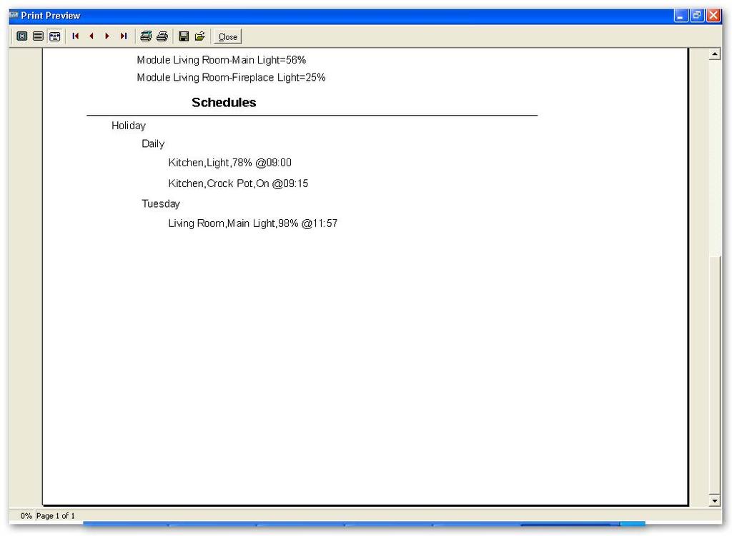
43 43

44 Touch Screen Operation The Bezel is magnetically attached to the inner metal panel. It can be removed by simply pulling at the sides. The front panel contains the USB connection as well as the Reset Switch. Reset Switch USB Connector 44


45 Welcome Screen The Welcome screen contains 3 buttons including Scenes, Manual and Schedule. The Scenes button will navigate to the scene control. The Manual button navigates to the Manual control screen allowing individual controls fro each device. The Scheduled Events button navigates to the Schedule events screen. In addition placing your finger over the BMB banner and holding for approximately 3 seconds will navigate to the Setup Screen. Scenes The Scenes screen allows the user to activate the Scenes that were programmed via the configuration Software. Simply push on the desired button to activate. Note, when the Touch Screen communicates to the X10 serial adapter a red indicator is seen on the top right corner of the display. This indicates that the Touch Screen is transmitting to the X10 Interface or waiting for a response. 45

46 Manual The Manual button navigates to the Rooms screen. This allows the user to choose the desired room and navigate to the devices in that room. 46
 will toggle the state of the device (On or Off) without the necessity of using the On/Off buttons.")
47 Manual Control The user can manually control a device by simply choosing the device to be controlled (the button will highlight as shown. The user can then control the following: On Off 25% Intensity 50% Intensity Use Up/Down arrows to control Intensity manually Pushing on the device button and holding for about a second (i.e. Light) will toggle the state of the device (On or Off) without the necessity of using the On/Off buttons. Please note that if an appliance module is chosen only the On and Off will be displayed. The Intensity bar shows the level of intensity of the actual lamp. When you navigate from Rooms screen to a specific room you will see red indicator in right upper corner indicating that Touch Screen is communicating to the X10 Interface. High lighted Button Intensity Bar 47


48 Scheduled Events The Scheduled events screen allows the user to enable scheduled events as programmed via the configuration software. To enable a scheduled event simply click on the desired schedule and the green LED in the button will highlight (the schedule will only be enabled if the Green LED is ON). Please note that multiple schedules can be enabled Press on schedules to get table of scheduled events In addition pressing on the header Schedules will allow the user to see a list of scheduled events. The list contains one week of events and is updated weekly. 48

49 Setup The Setup screen is displayed by pushing on the BMB banner on the welcome screen for approximately 3 seconds. The Setup screen allows the user to set the following: - Brightness : Display brightness - Contrast : Display Contrast - Time : The time that the display is on before backlight is shut off (setting to off (0) will keep display on all the time). - Click : Turns the audible key click On or Off Press the Save button to save the settings. 49

50 Set Time The Set time screen allows you to set the time and date. Press the Save button to save these settings. 50

51 Firmware and Screen Loader Programs Firmware Loader Program The program loader program allows the user to update the firmware in the Touch Screen. The update is downloaded to the Touch Screen via the USB cable. The procedure is as follows: Run the bfloader.exe program that is found in the Utilities folder (navigate to program files\ies\lighting Configuration\ utilities ) The following screen will be seen. Click on File and choose the file to be downloaded. The file will be in the firmware folder, which can be found at Program files\ies\lighting Configuration\ utilities\firmware The file will have the extension.ldr. Click on Program to download the file, the display may turn white or change colours during the download. Note that after the file is downloaded the Touch Screen will beep and reboot. After initializing the version number will appear on the display (i.e. for version n, you will see v1.33n in the upper left hand corner). 51
. The following screen will be seen.")
52 Screen Loader Program The Screen Loader Program allows the user to update the screens in the Touch Screen. The update is downloaded to the Touch Screen via the USB cable. The procedure is as follows: Run the scrloader.exe program that is found in the utilities folder (navigate to program files\ies\lighting Configuration\ utilities ). The following screen will be seen. Check the box called Reboot Touch Panel at Program Completion. The following screen will be seen. From the file menu choose the screen to be downloaded. The file will be in the screens folder which can be found at Program files\ies\lighting Configuration\ utilities\screens The file will end in.ies (i.e. Defaultscreens.ies). Click on program to download the file (The display may turn white or change colours during the download). Note, after the file is downloaded the Touch Screen will beep. The new screen should now be loaded. Please visit the BMB Electronics BV website at for Updated Graphics and Firmware. 52
Pronto. User Guide. User Guide
 Pronto EN 1 Pronto Copyright 2005 Royal Philips Electronics, Interleuvenlaan 72-74, 3000 Leuven (Belgium) Remark: All rights are reserved. Reproduction in whole or in part is prohibited without prior consent
CF3000 Dealer Diagnostic Tool Instruction Manual
 CF3000 Dealer Diagnostic Tool Instruction Manual Table of Contents: About the CF3000......3 Important Precautions......4 Components....5 Charging the CF3000......7 Licensing the CF3000.......8 Updating
RTC-Bridge User Manual
 RTC-Bridge User Manual Contents RTC-Bridge User Manual... 1 What is RTC-Bridge... 2 Getting started with RTC-Bridge... 2 Basic Configuration of the RTC-Bridge... 3 Setting House Number and Geographic Location...
GAMMA instabus Application Program Description. July CO Colour Touch-Panel
 Use of the application program Product family: Product type: Manufacturer: Name: Order no.: Name: Order no.: Display Display units Siemens UP 588/12 Colour Touch Panel UP 588/13 Colour Touch Panel (AC
1323x-RCM LEDs and Accelerometer Functionality 26. Using Home Status Control (HSC) Device Views.. 27 Home Status Control Device Properties...
 Device Views.. 27 Home Status Control Device Properties...") Contents About This Guide............................. 2 Audience............................................... 2 Revision History......................................... 2 Conventions............................................
Contents About This Guide............................. 2 Audience............................................... 2 Revision History......................................... 2 Conventions............................................
TeamBoard Quick Start #1
 www.touchboards.com 205 Westwood Ave.Long Branch, NJ 07740 1-866-942-6273 Sales@touchboards.com Quick Start #1 Welcome to! These Quick Start Cards address some basics, from installation steps to creating
Operating Manual. for HXOC Page 1 of 5
 Operating Manual for HXOC-003-000-02 Page 1 of 5 ESM PROGRAMMER: OPERATING MANUAL This handheld programming device is designed for setting the two selectable operating speeds available on the ebm-papst
quick guide 1 ON OFF OFF OFF OFF
 quick guide 1 ON 2 ON 3 ON 4 ON quick guide Leviton s Programmer/Remote Controller (Cat. No. VRCPG-0SG/ VRCPG-BSG/ RZCPG-0SG/ RZCPG-BSG) uses a wireless radio frequency called Z-Wave to act as a programmer,
ProntoPro Intelligent Remote Control. User Guide
 ProntoPro Intelligent Remote Control User Guide Table of Content Taking a First Look... 3 Intelligent Remote Control... 3 Before You Start... 5 Getting Started... 7 Activating the Remote Control... 7 Defining
Table of Contents. Taking a First Look 2 Intelligent Remote Control 2 Before You Start 4
 Table of Contents Taking a First Look 2 Intelligent Remote Control 2 Before You Start 4 Getting Started 6 Activating the Remote Control 6 Defining the Brands of Your Devices 7 Working with the Home Panel
Polaris G50 Dash cam incident recorder.
 Polaris G50 Dash cam incident recorder. Operation manual Quick Guide Thank you for purchasing the Polaris G50 DVR. The Polaris G50 DVR is a great product for capturing adventures and incidents both on
USER MANUAL. RC-43SL 6-Button Room Controller MODEL: P/N: Rev 3.
 USER MANUAL MODEL: RC-43SL 6-Button Room Controller P/N: 2900-300450 Rev 3 www.kramerav.com Contents 1 Introduction 1 2 Getting Started 2 2.1 Achieving the Best Performance 2 2.2 Safety Instructions
USER MANUAL. RC-74DL Master Room Controller MODEL: P/N: Rev 4
 KRAMER ELECTRONICS LTD. USER MANUAL MODEL: RC-74DL Master Room Controller P/N: 2900-000691 Rev 4 Contents 1 Introduction 1 2 Getting Started 2 2.1 Achieving the Best Performance 2 2.2 Safety Instructions
Using the NEC MobilePro
 4 Using the NEC MobilePro Powering On and Off Making Display Panel Adjustments Enabling the Suspend Switch Using Application Shortcut Keys Recording Voice Memos Using PC Cards Using CompactFlash Cards
INSTALLATION MANUAL for the Application ihc-mirf
 INSTALLATION MANUAL for the Application ihc-mirf Contents Introduction 3 Installing the application on a mobile phone 3 Settings 4 Control 12 Introduction The applications ihc-mirf (for mobile phones with
RZCPG USER GUIDE 1 ON OFF 2 ON OFF 3 ON OFF 4 ON OFF
 Programmer/Remote Cat. RZCPG USER GUIDE 1 ON OFF 2 ON OFF 3 ON OFF 4 ON OFF Compatible with TM enabled products! TABLE OF CONTENTS INTRODUCTION... 1 GENERAL OPERATION... 2 Primary Programmer/Remote Software
700TSU INSTALLATION MANUAL
 M 700TSU INSTALLATION MANUAL 2 Table of Contents Features...03 Specifications...04 Quick-Start...05 Remote Control...07 Hardware Installation...10 Software Installation...14 Touch Screen Driver Installation
GAMMA instabus Application Program Description. November CO Touch-Panel
 Use of the application program Product family: Product type: Manufacturer: Name: Order no.: Name: Order no.: Display Display units Siemens UP 588/2 Colour Touch Panel (AC 230 V) 5WG 588-2AB2 UP 588/22
Rotator Genius Instruction Manual v1.3.3
 Rotator Genius Instruction Manual v1.3.3 OVERVIEW Device connection overview 4O3A Signature Rotator Genius is a smart, high integration rotator controller. It uses an electromagnetic sensor for reading
IR-200F IrDA Mainboard Adapter
 IR-200F IrDA Mainboard Adapter The VScom IrDA Mainboard Adapter enables infrared wireless data communication by connecting the IrDA dongle to the built-in mainboard IR header connectors of your desktop
QUICK START. Installation & Programming Guide
 QUICK START Installation & Programming Guide PRECAUTIONS READ AND FOLLOW ALL SAFETY INSTRUCTIONS. CAUTION - RISK OF ELECTRICAL SHOCK. To prevent electrical shock, turn off power at the circuit breaker
USER MANUAL. VA-1USB-T USB Transmitter. VA-1USB-R USB Receiver MODELS: P/N: Rev 3
 KRAMER ELECTRONICS LTD. USER MANUAL MODELS: VA-1USB-T USB Transmitter VA-1USB-R USB Receiver P/N: 2900-300209 Rev 3 Contents 1 Introduction 1 2 Getting Started 2 2.1 Achieving the Best Performance 2 2.2
USER MANUAL. RC-43SL 6-Button Room Controller MODEL: P/N: Rev 1.
 USER MANUAL MODEL: RC-43SL 6-Button Room Controller P/N: 2900-300450 Rev 1 www.kramerav.com Contents 1 Introduction 1 2 Getting Started 2 2.1 Achieving the Best Performance 2 2.2 Safety Instructions
LED Commander 16/2 DMX controller. user manual
 LED Commander 16/2 DMX controller user manual Musikhaus Thomann Thomann GmbH Hans-Thomann-Strasse 1 96138 Burgebrach Germany Telephone: +49 (0) 9546 9223-0 E-mail: info@thomann.de Internet: www.thomann.de
STICK-KE1. Sunlite Touch Sensitive Intelligent Control Keypad. Overview
 STICK-KE1 Sunlite Touch Sensitive Intelligent Control Keypad Overview This complete stand alone wall-mounted DMX controller is the perfect answer to interior lighting control expectations. Along with a
Micro USB Lamp Kit ESSENTIAL INFORMATION. Version 2.0 DESIGN A STYLISH LAMP WITH THIS
 ESSENTIAL INFORMATION BUILD INSTRUCTIONS CHECKING YOUR PCB & FAULT-FINDING MECHANICAL DETAILS HOW THE KIT WORKS DESIGN A STYLISH LAMP WITH THIS Micro USB Lamp Kit Version 2.0 Build Instructions Before
STANDALONE INTERFACES USB-DMX 512 & 1024 CHANNELS V.1.1
 STANDALONE INTERFACES USB-DMX 512 & 1024 CHANNELS V.1.1 SUMMARY Hardware technical specifications... 3 Front Face of the 512 / 1024 channels interfaces... 4 Side Faces of the 512 / 1024 channels interfaces...
USER MANUAL. 7" Intelligent Digital Video Doorphone Indoor Unit TIP-DPH-INT7. Product Overview Product Description
 7" Intelligent Digital Video Doorphone Indoor Unit Product Overview...1 Product Description...1 Basic Function...2 UI Interface Introduction and Operation Instruction...3 Installation Instruction...18
ebook Users Guide For MyDistrict.net
 ebook Users Guide For MyDistrict.net You must download the ebook driver to any PC that is going to be used to update ebooks. There are two different drivers, one for Single Transfer ebook and one for Multiple
Elevation Window Control System
 Elevation Window Control System Keypad installation and user guide August 2013 copyright by ASSA ABLOY WARNINGS Read these instructions prior to the activation of the keypad. Save this user guide in a
Table of Contents. Chapter 1 Introduction Chapter 2 Quick Install... 7
 AVA-88 WELCOME Congratulations on purchasing the AVA-88. The AVA-88 integrates multiple complicated control, automation and internet protocols into one simple plug-and-play device. It is a central controller
**CHECK PIN CONFIGURATIONS. APPLYING POWER TO THE DMX INPUT WILL DAMAGE THE CONTROLLER**
 Page 1 EASY INSTALLATION 1. Mount an electrical box inside the wall The controller can be installed in any standard electrical backbox. If you use a double size box, you can insert the power supply inside.
PRODUCT MANUAL Duet DMX & Wireless RGB-W Controller
 Product Description Solid Apollo LED s new wall mounted Duet DMX & RGB-W LED Controller has been created to control LED light fixtures in three different ways. Users can independently control DMX enabled
Wireless RAK system setup guide
 Wireless RAK system setup guide 1 What you need to get started 2 Create a new Rasoft Pro Project File 2.1 Project name and House numbers 2.2 Save Locations 2.3 Adding rooms 2.4 Adding channels 2.5 Adding
lumentouch SPECIFICATION SHEET Client: Project name: Order #: Type: Qty: FEATURES AND BENEFITS PACKAGE CONTENT HOW TO ORDER LTO
 Client: Project name: Order #: Type: Qty: FEATURES AND BENEFITS Flat wall mounted lighting controller Universal mounting plate compatible with any electrical backbox MINI-USB connection for software programming
KRAMER ELECTRONICS LTD. USER MANUAL MODEL: RC-74DL Master Room Controller. P/N: Rev 5
 KRAMER ELECTRONICS LTD. USER MANUAL MODEL: RC-74DL Master Room Controller P/N: 2900-000691 Rev 5 Contents 1 Introduction 1 2 Getting Started 2 2.1 Achieving the Best Performance 2 2.2 Safety Instructions
Quick Reference Guide
 LΩGIC 16X36 Quick Reference Guide About this Guide Disclaimer The LΩGIC 16X36 Quick Reference Guide (QRG) only contains the product s connection and mounting information, as well as the menu options and
How to Upgrade NIC OS to Windows Embedded Standard 7
 Document Number: APL-00207 Updated 3/2/2015 Rev-A How to Upgrade NIC OS to Windows Embedded Standard 7 NIC units built between October 2010 and February 2015 were shipped with Windows Embedded Standard
Architectural Controllers
 Architectural Controllers SCSC Intelligent Controllers can be installed in any commercial or residential environment for the control of SPD-Smart window glass or plastic. This flexible, highly configurable,
Software Setup Instructions for the Foster Control System used in the Explora Dome Observatories
 Software Setup Instructions for the Foster Control System used in the Explora Dome Observatories Contents Pages 3 & 4 The new tic counter system & home position sensor Page 5 Control Boxes Pages 6-8 Down
Click Install View Touch. Installation starts. Click Next. Click Finish.
 1. Please read the instructions carefully. Improper installation may cause permanent damages, which may not be covered by the warranty. 2. Check all the parts in the package against the following parts
Options. Parts List. Optional Expansion Hub Optional Ignition Module Optional Memory Card
 Options Optional Expansion Hub Optional Ignition Module Optional Memory Card View boost, speed, and gear on the LCD Display. View the ignition changes on the LCD Display. Log and store map data. Card storage
S16T user guide. Origen
 S16T user guide Origen S16T user guide Thank you for purchasing this Origen ae htpc enclosure. We recommend that you read this user guide thoroughly before installation. Origen ae has rapidly grown to
Wireless RS485 for KACO Link
 Wireless RS485 for KACO Link Introduction The SP PRO KACO Managed AC Coupling provides a method of linking the KACO Powador xx00 and Powador xx02 series grid tie inverters to the SP PRO AU or GO Series
elan-rf-003 Manual / rev.5 Page 1 of 13
 Page 1 of 13 1. Introduction... 3 2. Installing the elan-rf-003, IP address... 4 3. Logging in to the web interface elan-rf-003... 4 4. Settings... 5 Configuration panel... 6 Description of functions...
Rotator Genius Manual
 Rotator Genius Manual During the time of writing the firmware and app versions are 1.4.3 Table of Contents 1. Introduction and Overview...2 2. Powering Up!...2 2.1 Buttons and Controls...3 2.2 Network
CncGcoder Models HD & HDx Manual
 CncGcoder Models HD & HDx Manual Table of Contents WELCOME... 3 IN THE BOX... 4 Optional Accessories...4 HANDHELD OVERVIEW... 5 Overview...5 Charging the Battery...6 Turning On and Off...6 Plugging in
890 Pro Harmony Remote. User Manual version1.0
 890 Pro Harmony Remote User Manual version1.0 Table of Contents INTRODUCTION...1 GETTING TO KNOW YOUR HARMONY REMOTE...2 BEGINNING THE SETUP PROCESS...3 USING YOUR HARMONY REMOTE...4 USING THE REMOTE WITH
Introduction. EC2 User Manual with Technical Addendum 1.0 1
 Introduction The EC2 Explorer Experience is a self-serve kiosk that simulates wind and reflective glare conditions. Key features that can aid the associate/customer in making a decision on their sunglass
Table of Contents. Introduction 2 1. Intelligent Remote Control 2 2. Charging the Remote Control 3
 Table of Contents Introduction 2 1. Intelligent Remote Control 2 2. Charging the Remote Control 3 Getting Started 6 1. Activating the Remote Control 6 2. Selecting a Device 7 3. Operating a Device 8 4.
DODGE Challenger Charger Journey. 6-Pin Video Input Cable 6-Pin Audio In/Out Cable GPS Magnetic Antenna
 CHRYSLER 2011-2014 300c DODGE 2011-2014 Challenger 2011-2014 Charger 2011-2014 Journey FIAT 2011-2014 Freemont Plug and Play connectors make installation simple and easy. Utilizes the latest mapping version
Comfort Optimizer Installation Instructions
 Congratulations on choosing the best all around load calculation program available. Along with this instruction manual should be the installation CD. Before we can install the Comfort Optimizer, we have
Hardware technical specifications Front Face of the 512 / 1024 channels interfaces LED 7-segments display operation:...
 SUMMARY Hardware technical specifications... 4 Front Face of the 512 / 1024 channels interfaces... 5 LED 7-segments display operation:... 5 LED 7-segments Sleep option:... 6 selection Mode button... 6
POWER. allows users to interface a third party control system with the devices on a VN Matrix network.
 The Extron VNM Enterprise Controller 00 is a dedicated control device for managing large VN-Matrix systems. The controller allows users to view, manage, and dynamically control multiple VN-Matrix systems
application software
 application software application software RF input product Electrical / Mechanical characteristics: see product user manual Product reference Product designation TP device RF devices 8565 52 xx 8565 62
USER MANUAL. RC-76R/RC-78R Room Controllers MODEL: P/N: Rev 2
 KRAMER ELECTRONICS LTD. USER MANUAL MODEL: RC-76R/RC-78R Room Controllers P/N: 2900-300253 Rev 2 Contents 1 Introduction 1 2 Getting Started 2 2.1 Achieving the Best Performance 2 2.2 Safety Instructions
Wireless Control Systems
 Wireless Control Systems Leading the way in intelligent automation contents Range Overview Typical Installations Transmitters Combined Modules Receivers Accessories Programming Switching & Dimmer Functions
Dino-Lite Digital Microscope User Manual. User Manual
 User Manual Dino-Lite Digital Microscope User Manual Table of Contents Chapter 1 - Getting Started 1.1 Installation Instructions for Windows XP...1 1.2 Instructions for Windows Vista Users...8 Chapter
SYNERGY GLOBAL INC. Toll Free : Fax :
 SYNERGY GLOBAL INC Toll Free : 1-888-865-6888 Fax : 510-226-8968 Email : info@rackmountmart.com LCD1U15-03 series & LCD1U17-10 series User s manual 4-in-1 (KVM switch, Keyboard, LCD display, touch pad)
CAM-KIT6. User Manual. Connects2Vision. Mirror with DVR & Rear Camera PRODUCT FEATURES:
 User Manual CAM-KIT6 Mirror with DVR & Rear Camera PRODUCT FEATURES: Display: 5 inch Speaker: Built in MIC: Built in Mini USB: 5V 2A Micro SD Card Support: 32G max (not supplied) Rear Camera Input: 2.5mm
User s Manual ITR-CS15D
 User s Manual ITR-CS15D Copyrights 2012 TALOS INTEGRATED TECHNOLGIES. All rights reserved. The information in this document is subject to change without prior notice in order to improve reliability, design
Model: Touchpad (TFT) Model: TFT
 Model: TFT") Model: Touchpad (TFT) Model: TFT 1 Model: Touchpad TFT Table of Contents Set-Up Product Image Table of Contents Installation Procedure Initial Setup Setting the Clock LCD Display My System Locking the
Model: Touchpad (TFT) Model: TFT 1 Model: Touchpad TFT Table of Contents Set-Up Product Image Table of Contents Installation Procedure Initial Setup Setting the Clock LCD Display My System Locking the
lightwaverf Lightwave Link Model No. JSJSLW500 Instruction Manual Connect Series
 lightwaverf Lightwave Link Model No. JSJSLW500 Instruction Manual Connect Series www.lightwaverf.com Get Started How do I get started? Power the Lightwave Link and connect it to your home WiFi router.
KNOW THE OPTIONS for your next hunt!
 KNOW THE OPTIONS for your next hunt! The Day6 PlotWatcher Time Lapse HD Video Camera records up to 84 hours of activity at a potential hunting location onto a USB drive. All of the activity can then be
DMX Downlight Driver. LDD-DMX User Manual
 DMX Downlight Driver LDD-DMX 2016 Digilin Australia. Document Rev : 5. 2-4 Nov ember 2016 Product spe cifications are subject to change without no tice. Table Of Contents Safety Notes... 2 Introduction...
equipment, etc.) by the learning process or selecting them on a code list. EGi DOMOS2 Universal
 by the learning process or selecting them on a code list. EGi DOMOS2 Universal") User s Manual English 005180 Avda. Almozara, 79 50003 ZARAGOZA - Spain Phone +34 976 40 53 56 Fax +34 976 40 53 54 http//: e-mail: info@egiaudio.com 40100 Remote control Thank you for choosing the EGi
User s Manual English 005180 Avda. Almozara, 79 50003 ZARAGOZA - Spain Phone +34 976 40 53 56 Fax +34 976 40 53 54 http//: e-mail: info@egiaudio.com 40100 Remote control Thank you for choosing the EGi
INSTALLATION INSTRUCTIONS MODEL MRC44KP MRC44 KEYPAD
 INSTALLATION INSTRUCTIONS MODEL MRC44KP MRC44 KEYPAD Page 2 Model MRC44KP Model MRC44KP Page 3 TABLE OF CONTENTS Section Title MRC44 Keypad Feature Descriptions...4 Installation MRC44 Keypad Physical Location
Glass Dimmer Touch Control du02
 Glass Dimmer Touch Control du02 User Manual Installation Manual George summers close, Medway City Estate, Rochester, Kent ME2 4EL Tel: +44 (0)1634 290 772, Fax: +44 (0)1634 290 773 mail@energy-solutions.co.uk
Onetouch Controller Driver
 Onetouch Controller Driver OS: Windows 98, 98SE, NT, ME, 2000, XP (Win NT not support USB controller) Support interface: USB, Serial Index.P1 Installation P2 Serial Controller installation....p2 USB Controller
DIMENSIONS D3200 SETUP SOFTWARE INSTRUCTION MANUAL
 DIMENSIONS D3200 SETUP SOFTWARE INSTRUCTION MANUAL March 10, 2003 Paul Soccoli Michael Grinshpoon Dimensions D3200 Software Instructions Page 2 of 29 TABLE OF CONTENTS Data Manager...3 Startup Screen...3
Welcome to ThinkEssentials
 User s Manual Welcome to ThinkEssentials Figure 1: Sample room and device layout with ten devices ThinkEssentials software includes the following features: Set up and control up to 230 Z-Wave devices Draw
Model No user manual PRO
 Model No. 258011 user manual PRO Index Introduction Features Specification Button definition Operation Instruction Power ON/OFF LCD backlight Five main functions PinTest QuickTest Browse Delete Settings
& Technical Specifications
 User Manual & Technical Specifications User manual Contents Pidion BM-170 Technical specifications... 2 Micro Rolltalk basic package... 3 Micro Rolltalk functions and buttons... 3 Preparing Micro Rolltalk...
Installation Instructions for the RGB DMX Stick 3 Controller
 Installation Instructions for the RGB DMX Stick 3 Controller #RGB-DMX-CONT-STICK3 Installing the Controller 1. Mount an electrical box inside the wall The controller can be installed in any standard electrical
KRAMER ELECTRONICS LTD. USER MANUAL MODEL: RC-76R/RC-78R Room Controllers. P/N: Rev 5
 KRAMER ELECTRONICS LTD. USER MANUAL MODEL: RC-76R/RC-78R Room Controllers P/N: 2900-300253 Rev 5 Contents 1 Introduction 1 2 Getting Started 2 2.1 Achieving the Best Performance 2 2.2 Safety Instructions
M2DIS. User Manual.
 M2DIS User Manual www.audac.eu 2 Index Introduction 4 Caution servicing 4 User interface 5 Login screen 5 Main screen 6 Output settings 8 Test signals 10 Sound settings 11 Settings screen 12 Input Configuration
705 INSTALLATION MANUAL
 705 INSTALLATION MANUAL 2 Table of Contents Features...03 Specifications...04 Quick - Start...05 Remote Control...07 Hardware Installation...10 705 Models Additional Info...14 Owner s Record...15 3 Features
ADVANCED DRIVER PROGRAMMING. EVERset User Manual
 ADVANCED DRIVER PROGRAMMING EVERset User Manual User Manual Rev1.4 10/03/2018 Table of Contents 1. Introduction... 2 2. Computer System Requirements... 2 3. Definitions System Definitions... 3 Setting
Video Interface for Audi with MMI 3G System. User Manual. Car-Solutions.com
 Video Interface for Audi with MMI 3G System User Manual Car-Solutions.com 2 Contents 3 Welcome - What' in the box? 4 About Interface - Dimension 5 - External Appearance 6 Connector Pin Assignment 7 8 9
Nearus USB2.0 Camera Manual NU-350-USB2PTZ-B
 Nearus USB2.0 Camera Manual NU-350-USB2PTZ-B Safety Tips Please read this manual carefully before installing the camera. Keep the camera away from violent vibration, physical stress, moisture, extreme
USER MANUAL. SL-1N Master Room Controller MODEL: P/N: Rev 1
 KRAMER ELECTRONICS LTD. USER MANUAL MODEL: SL-1N Master Room Controller P/N: 2900-300399 Rev 1 Contents 1 Introduction 1 2 Getting Started 2 2.1 Achieving the Best Performance 2 2.2 Safety Instructions
Welcome 1. Precaution
 Table of Contents EN Precaution....2 Preparation.. 4 Standard accessories....4 Parts Names & Functions...5 Computer System requirements.... 6 Technical Specifications 7 Install the software.. 7 Start Microscope.8
USER MANUAL. RC-43T Remote Controller MODEL: P/N: Rev 3
 KRAMER ELECTRONICS LTD. USER MANUAL MODEL: RC-43T Remote Controller P/N: 2900-300301 Rev 3 Contents 1 Introduction 1 2 Getting Started 2 2.1 Achieving the Best Performance 2 2.2 Safety Instructions 3
Custom Monitor Configuration Guide
 F1DN104K-3 F1DN108K-3 Custom Monitor Configuration Guide May, 2018 LNKPG-00559 Rev. A00 Introduction The Secure KM Switch Viewing and Interacting with Multiple Systems Simultaneously The Secure KM Switch
USER MANUAL RC-76M/RC-712M MODEL: P/N: Rev 3
 KRAMER ELECTRONICS LTD. USER MANUAL MODEL: RC-76M/RC-712M P/N: 2900-300329 Rev 3 Contents 1 Introduction 1 2 Getting Started 2 2.1 Achieving the Best Performance 2 2.2 Safety Instructions 3 2.3 Recycling
USER MANUAL. RC-54DL KNET Auxiliary Control Panel MODEL: P/N: Rev 2
 KRAMER ELECTRONICS LTD. USER MANUAL MODEL: RC-54DL KNET Auxiliary Control Panel P/N: 2900-300130 Rev 2 Contents 1 Introduction 1 2 Getting Started 2 2.1 Achieving the Best Performance 2 3 Overview 3 3.1
Wireless Touchscreen Installation Guide
 Wireless Touchscreen Installation Guide Safety Declaration of Conformity The Systemline Wireless Commander has been designed and independently tested to be in compliance with the following standards:
GPS mini Watch User Manual Introduction. Getting Started. Caution: Step 1) Know your Watch:
 Know your Watch:") Watch User Manual Introduction Thank you for purchasing the GPS Watch. This GPS Watch is packed with personal Training features like speed, trip time, laps, etc. Watch features include but not limited
Watch User Manual Introduction Thank you for purchasing the GPS Watch. This GPS Watch is packed with personal Training features like speed, trip time, laps, etc. Watch features include but not limited
Wise Scene Box. Wireless scene setting for your home & garden...
 9:41 AM 100% 9:41 AM 100% Wise Scene Box Wireless scene setting for your home & garden... Introduction... The Wise Scene Box is a 4 circuit dimmer that is controlled using wireless keypads. This box has
EU Driver s Hours Rules covered by Digifobpro. Table of contents
 EU Driver s Hours Rules covered by Digifobpro Digifobpro provides analysis of Driver Cards both in it s Quick View and Driver Card - Download features ( see Digifobpro Functions page 4). There follows
FPO MLC 62 RS MK. Simple and Easy-to-use A/V System Control MEDIALINK CONTROLLER FOR MK-TYPE JUNCTION BOXES. MediaLink
 MediaLink MLC 62 RS MK MEDIALINK CONTROLLER FOR MK-TYPE JUNCTION BOXES Eight customizable backlit buttons Mounts in a 35 mm deep single size MK junction box for UK, Singapore, Hong Kong and other markets
UI-IP8-DP Programmable 8-button IP Keypad Wall plate with PoE
 User s Manual UI-IP8-DP Programmable 8-button IP Keypad Wall plate with PoE Control of IP enabled devices on your LAN using a single-gang Decora Style Wall plate UMA1261 Rev A CUSTOMER SUPPORT INFORMATION
FPO MLC 62 RS EU. Simple and Easy-to-use A/V System Control MEDIALINK CONTROLLER FOR EUROPEAN JUNCTION BOXES. MediaLink
 MediaLink MLC 62 RS EU MEDIALINK CONTROLLER FOR EUROPEAN JUNCTION BOXES Simple and Easy-to-use A/V System Control Eight customizable backlit buttons Mounts in a single size European junction box and includes
LICENSE PLATE RECOGNITION SETUP AND FIELD INSTALLATION GUIDE
 LICENSE PLATE RECOGNITION SETUP AND FIELD INSTALLATION GUIDE This document was created to benchmark the settings and tools needed to successfully deploy LPR with the ipconfigure s Enterprise Surveillance
1029 INSTALLATION MANUAL
 1029 INSTALLATION MANUAL 2 Table of Contents Features 03 Specifications 04 Quick Start..05 Remote Control.07 Capacitive Touch..10 Hardware Installation 11 1029CNH / 1029CNV / 1029TNH / 1029TNV Models Additional
ipad and iphone Basics
 ipad and iphone Basics 1 Physical Attributes On/Off Sleep/Wake Silent/ Screen rotation Lock Sight/Camera Or On/Off Sleep/Wake iphone 10 has no home button! Volume: Up/Down Not all 2 Multitasking The multitasking
Table of Contents. Chapter 1. Safety Precautions Notice Chapter 2. Components and accessories Chapter 3. Camera components...
 P. 770.270.1394 F. 770.270.2389 865 Marathon Parkway Lawrenceville GA 30046 P. 770.270.1394 F. 770.270.2389 865 Marathon Parkway Lawrenceville GA 30046 Table of Contents Chapter 1. Safety Precautions Notice...
USER GUIDE FOR NETmc MARINE Four264 DVR
 USER GUIDE FOR NETmc MARINE Four264 DVR Rev. 2 Firmware 1.4.7 August 2016 NETmc Marine Four264 Manual-Rev.1 August 2016 1 of 16 Contents 1. Introduction... 3 2. Hardware Description and Connections...
1. CONTROL OF THE LIVING ENVIRONMENT WITH ENTIALIVING SYSTEM 4 2. LIGHTING CONTROL WITH ENTIALIVING SYSTEM 5
 User manual KAZALO 1. CONTROL OF THE LIVING ENVIRONMENT WITH ENTIALIVING SYSTEM 4 2. LIGHTING CONTROL WITH ENTIALIVING SYSTEM 5 3. TEMPERATURE CONTROL WITH ENTIALIVING SYSTEM 6 4. SHADING CONTROL WITH
User s manual 19 1U RACKMOUNT CONTROL CENTER. Rack-KVM in-1 TABLE OF CONTENTS INTRODUCTION... (KVM switch, Keyboard, LCD display, touch pad)
") Rack-KVM9000 User s manual 4-in-1 (KVM switch, Keyboard, LCD display, touch pad) 19 1U RACKMOUNT CONTROL CENTER Rev 1.1 TABLE OF CONTENTS INTRODUCTION... FEATURES.... PACKAGE CONTENTS..... TECHNICAL SPECIFICATIONS...
Rack-KVM9000 User s manual 4-in-1 (KVM switch, Keyboard, LCD display, touch pad) 19 1U RACKMOUNT CONTROL CENTER Rev 1.1 TABLE OF CONTENTS INTRODUCTION... FEATURES.... PACKAGE CONTENTS..... TECHNICAL SPECIFICATIONS...