DIRECT LINK FLASH TUNER
|
|
|
- Simon Stewart
- 6 years ago
- Views:
Transcription


1 DIRECT LINK FLASH TUNER Installation and User Manual Rev 3.0 This Guide is intended to answer basic Direct Link tuning questions and to act as a Quick Start Guide. It is not intended to be encyclopedic on the tuning process - only to answer basic questions about Direct Link. This Guide will give some example tables that have been proven to work in the past, but the tuner/dealer is ultimately responsible for the final tune on any bike.
2 INTRODUCTION... 3 HOW IT WORKS... 3 ABOUT THIS MANUAL SETUP AND INSTALLATION WHERE TO GET THE SOFTWARE INSTALL DIRECT LINK FLASH TUNER RUN DIRECT LINK FLASH TUNER CONNECT USB CABLE POWER UP THE DIRECT LINK FLASH TUNER POWER UP TO AUTOMATICALLY INSTALL DRIVERS UPDATE THE SOFTWARE CONFIRM COM PORT FOR COMMUNICATION TROUBLE-SHOOTING COM PORT ISSUES TOOLBAR ICON DESCRIPTIONS MAIN MENU TAB MENU DIRECT LINK TOOLBAR BUTTONS KEY FEATURES CREATING A BACKUP LOADING A MAP IMPORTANT TABLES VE Table Spark Table AFR Ratio Table Cranking Fuel Idle Table IAC Table Acceleration Table Decell (Deceleration) Table Closed Loop Warm-up Fuel table ADDITIONAL CHECKS Knock Sensor Engine Parameters Calibration Note Throttle grip PROGRAM THE CALIBRATION INTO THE ECU SAVE ORIGINAL CALIBRATION PROGRAM PROGRAMMING STATUS HOW TO SAVE THE MODIFIED CALIBRATION SAVE AS CALIBRATION INFORMATION HOW TO CHANGE UNITS
3 6.1 OPTIONS MONITOR REAL-TIME DATA (GAUGES/METER DISPLAY) MONITOR DATA CHANGE CHANNELS CHANGE VISIBLE PARAMETERS TURN IGNITION TO RUN COMMUNICATE MONITOR REAL-TIME DATA (STRIP CHART DISPLAY/METER DISPLAY) VIEW DATA CHANGE CHANNELS Channel Display TURN IGNITION TO RUN COMMUNICATE AUTO-MAPPING SELECT STRIP CHART LOGGING DATA WITH A DYNO LOGGING DATA WITH MOBILE DYNO GLOSSARY
4 Introduction The Direct Link Kit will provide the tuner with the tools and necessary data to maximize the potential of the installed upgrades. The system is designed for Harley-Davidson Fuel Injection equipped motorbikes. How it Works The ECU is basically a calculator that sends signals to the injectors. The sensors include the temperature of the motor (Harleys head temperature sensor), outside ambient temperature and pressure (altitude), throttle position (TPS), engine speed (RPM) and load (KPA or MAP, manifold absolute pressure). The newer models, (2008 and later), also have a narrow band O2 sensor and actually run in closed loop when you tell it to. The ECU combines all data gathered by the above mentioned sensors and compares it to the scribed maps that have been set up at the factory and makes adjustments so that the engine works at its best given the circumstances. About this Manual The Direct Link User s Guide is a comprehensive guide that contains procedures you will need in order to work with this software. This manual is organized by chapters to assist novice users with getting started. Many topics covered in this manual are also covered in the help menus available in the program itself. This Guide/Manual has been written thinking that not only professionals will use it, but also non-professionals. That is the reason it is written in a non-technical way. 3


5 1. Setup and Installation 1.1 Where to get the Software Insert the CD-ROM from TechnoResearch Inc. into the DVD/CD-ROM drive of the computer OR download from our website ( go to Support > Downloads). 4


6 The first download link will be for the software. This is where you can also find manuals and guides. 1.2 Install Direct Link Flash Tuner After auto-run, press install and follow the installation prompts. 1.3 Run Direct Link Flash Tuner With the red or blue USB key plugged in to the computer, double-click on the Direct Link icon on the desktop to run the program. This will install the necessary driver for the USB hardware key. 5


7 1.5 Connect USB Cable Connect the USB computer cable (shown below at left) to the Vehicle Communication Module. The module is shown below, with the USB port on the right side of the metal endplate. Connect the other end to the PC s second USB port. VCM-TR1 VCM-TR3 NOTES: The supplied USB Hardware Key with this software is for use on a single vehicle only. When the USB Hardware Key is used to program a vehicle, it will be permanently attached to that vehicle, and cannot be used on any other for programming. You can use any key, empty or used, to start and use this software. Only when programming will the software check that the key is empty and lock it to THAT ECU. If the key has been used before, the software will check that the key will match the ECU. If not, the software will be closed. NEVER plug in multiple hardware keys. For example: do not plug in a Direct Link key and a Centurion key at the same time! 6
8 1.6 Power up the Direct Link Flash Tuner Connect the Vehicle Communication Cable to the DB-15 port on the other end of the Vehicle Communication Module (shown below). Connect the other end to the motorcycle s data link connector. If you cannot locate your bike s data link connector, see below or please consult your motorcycle user manual. Location of Data link connector: Touring models: Underneath the right side cover. ( Underneath the left side cover) Softail models: Underneath the seat. Dyna models: Underneath the left side cover. Sportster models: Underneath the left side cover. VRSC: Underneath the front side neck cover. 1.7 Power up to Automatically Install Drivers The VCM is powered by the battery of the motorcycle. Make sure the ignition is ON and the RUN switch is ON. The light on the VCM should be lit. This will cause the software to search for and install the cable drivers. 7

9 1.8 Update the Software After the Direct Link software is installed, run the updater to get the latest program versions including the calibrations and the manuals. Click Updater in the bottom right corner: 8


10 Select Install New Release and let the Updater run to completion. 1.9 Disclaimer/Language Selection After the update is finished, open the main menu again (double-click DL Icon) and click Accept to agree to the terms of use and select a language preference to launch to software. 9

 is not powered, then the correct COM Port will not appear (indicated by an illuminated LED).")
11 The software will open to the Programming screen. This screen is where you will do a lot of your work. You should play with this screen and practice opening and closing editing tables and connecting to the motorcycle. Each table you edit will change something on the motorcycle and you will always program the ECU from this screen Confirm COM Port for Communication Under Communication, select Port Setting. Important: If the Direct Link hardware (VCM) is not powered, then the correct COM Port will not appear (indicated by an illuminated LED). To rectify, press Cancel and power the Direct Link hardware by turning on the ignition switch and making sure the engine stop/run switch is in the RUN position. Once the LED light is on, the Direct Link hardware is on, select Communication and Port Setting again to select the correct COM Port. 10

12 Either select the COM Port manually using the arrows or click the box to use USB: Click OK and then test connection by clicking ECU Info on the programming screen. If connection is successful, the ECU Info section will populate with the bike s current information: If connection fails, see the next step for trouble-shooting COM port connection issues. 11


13 1.11 Trouble-shooting COM Port Issues If the COM port cannot be selected and checking the USB box does not allow connection, it means that the driver for it was not correctly installed when installing the software. Go to the computers Control Panel, select Hardware and Sound, select Device Manager. Expand Other Devices or COM Ports to locate the serial converter or key. If the COM port is not showing, the yellow triangle icon will appear: IMPORTANT: This means that the driver was not correctly installed when installing the Centurion U/UE/M/S software. When you right click and select Update Driver Software, you can manually browse and point the search at your CD/DVD drive if the software CD is in, OR search automatically and the files should be pulled. After the correct device driver is installed or updated, the window will look like this: Go back to the Port Setting window in the software and make sure the corresponding number is selected in this case, COM14 OR check the box for USB. Test for connection again by selecting ECU Info. 12
14 2. Toolbar Icon Descriptions 2.1 Main Menu The Direct Link main menu offers a variety of commands. Below the main menu are the Toolbar Buttons, which offer quick access to the most often used commands. 2.2 Tab Menu File Menu: Commands to open, export, backup or save a file, close an active window, and quit the program Edit-Table: Access to editable tables and engine settings View: Contains commands related to what mode you are viewing Communication: Commands for connecting, disconnecting, and programming Options: Trace and data record settings, access to Mobile Dyno, settings to change units and colors Help: Displays a variety of help commands 13
15 2.3 Direct Link Toolbar Buttons The toolbar buttons allow one-click access to the most frequently used commands. Open Calibration Open Data Log Save As Print Reflash Gauges/Meters Strip Chart PVI Connect Disconnect Recording ON/OFF Channels/Mode Auto map/mobile Dyno Front & Rear Fuel Table Front & Rear Spark Table AFR Table 14
16 3. Key Features 3.1 Creating a Backup Always save the original calibration before programming the new calibration. That way, the motorcycle can be restored to stock at any time. Precautions: During the backup and programming, the ECU must be powered correctly. Therefore, we recommend removing the LIGHT fuse and using a charger to be sure that the voltage is correct. With the ignition switch on and the engine stop switch in the RUN position, click Backup Map. This will back up the original map from the ECU so that, at a later date, the motorcycle can be restored to stock if needed. 15


17 Select a location and name for the Backup Map and click on Save Direct Link will now read and save the original bike map. After the status bar has reached 100, check for the green PASS to ensure that all operations have concluded successfully. Note: Do not disconnect the USB Hardware Key. This could damage the key. 16
18 3.2 Loading a Map Before loading a map, check what map is in the motorcycle ECU by pressing the button ECU Info. The Application # text box will show the correct map model (105, 127, 176, etc.) Find the map best suited to load (based on application #) by opening a calibration via File > Open Calibration > Modified or click the Open Calibration icon. This will open a file selection window. (The Application # mentioned is usually in the end of the map file name. 17

19 Navigate the folders by year/model, select a map and click Load. Once loaded, the Calibration Information can be reviewed and compared with that of the ECU. 18
 The")


20 3.3 Important Tables (Check before first flash) The following tables can be found under the Edit-Table drop down, or by using the toolbar buttons shown: VE Table 19

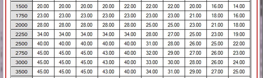
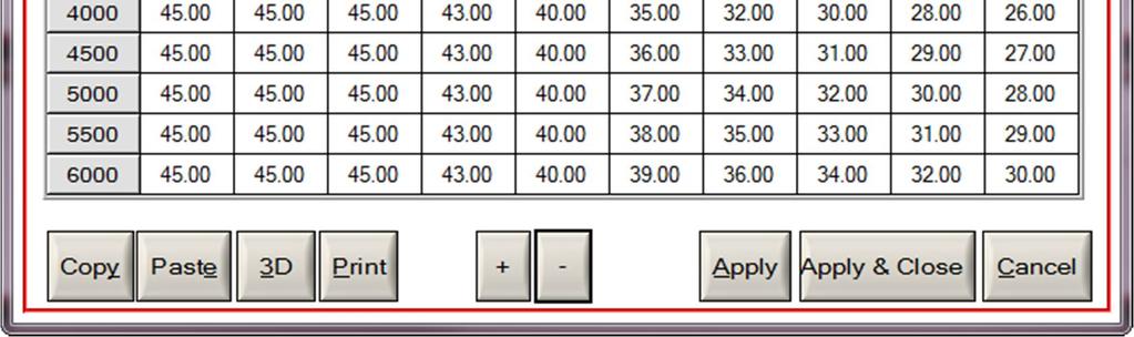
21 3.3.2 Spark Table 20


.")
22 3.3.3 AFR Ratio Table The values in the AFR (Air-Fuel Ratio) table are calculations that the ECU uses to determine the injector pulse width. The AFR does not actually change. This is the main fuel table that the ECU will try to achieve. The tuning process changes the VE (Volumetric Efficiency) tables so that the live AFR data is as close to AFR table. You can, and should, change the VE s on each cylinder separately. They each have different requirements and the fuel injectors may not be matched for flow. There are (2) methods to accomplish this Set the AFR Ratio Table in open loop but close to the final Target values. The other method is to set all of the values to the same constant ( ). Once the values are in place, click on the Apply button to apply the changes, then the OK button to conclude the modification. Note: When working on the closed-loop models, changing the AFR value to 14.0 or below disables closed-loop operation which makes VE table tuning possible. 21

23 3.3.4 Cranking Fuel Found under Edit-Table drop down menu. Make sure to check this table. The cold temperature numbers should have more fuel than the hot temperature numbers. Double click on an msec cell and use the up and down arrow to adjust. The values above a temperature of 233F may have to be adjusted up or down to get the bike to start quickly. Click OK. See this example of a typical Cranking Fuel table: 22
24 3.3.5 Idle Table Found under Edit-Table drop down menu. Make sure to check this table. Double click on an RPM cell and use the up and down arrow to adjust. Remember to let the engine get to working temperature before making any changes. Click OK. See this example of a typical idle table: 23

25 3.3.6 IAC Table Found under Edit-Table drop down menu. Make sure to check this table. This table may need to be adjusted while tuning to make sure bike is idling up on startup, and when at operating temperature, the idle is stable. Check live data and verify that the actual stepper counts are not lower than the programmed stepper counts. The actual Steps should be the same or slightly lower than the programmed values. Double click on a STEPS cell and use the up and down arrow to adjust. Click OK. See this example of a typical IAC Table: 24

26 3.3.7 Acceleration Table Found under Edit-Table drop down menu. Make sure to check this table. The accel table needs to be adjusted during tuning so the bike will have crisp response when blipping the throttle and no black smoke comes out of the exhaust. Double click on a STEPS cell and use the up and down arrow to adjust. Click OK. TIP: Create a table that lists the changes in calibrations that have been modified just in case you want to go over your own work before saving. 25
27 3.3.8 Decell (Deceleration) Table Found under Edit-Table drop down menu. Make sure to check this table during tuning if decell popping is occurring. This table allows the removal of a small amount of fuel during a decrease in throttle position, or during a decrease in manifold pressure. This fuel gets subtracted from the base pulse width calculation. Larger values increase the fuel removed. Smaller values decrease the fuel removed. Double click on a STEPS cell and use the up and down arrow to adjust. Click OK. 26


28 3.3.9 Closed Loop Found under Edit-Table drop down menu. This table can be left alone for tuning, as the AFR Table has been set so the bike will always be in open loop and not be using the factory Oxygen sensors. Only when the AFR table is at 14.6 will this table be active and used. There are (2) types of closed loop systems now. The older bikes use closed loop biasing and the new bikes do not. The new bikes can be set from for closed loop. The old bikes with the bias table have the AFR value or millivolt setting centered at 450volts. Setting this table to 680 will yield something like AFR Value. You cannot set this mv value much higher, as the O2 sensor will not switch properly and will drive the fuel rich. The sensor needs to switch around a center point. 27
29 Warm-up Fuel table Found under Edit-Table drop down menu. Make sure to check this table. This table needs to be minimized as much as possible so gas is not being wasted on warm-up. Double click on an AFR cell and use the up and down arrow to adjust. Click OK. See this example of a typical Warm-up Fuel Table: 28

30 3.4 Additional Checks (Check before first flash) The following tables can be found under the Edit-Table drop down menu: Knock Sensor This should be turned on when the timing table is being adjusted and click OK to save Engine Parameters The settings for Engine size and injector size should be set to match what the engine really is. These parameters may need to be adjusted to alter the VE tables off of maximum values. Try to leave the cubic inch values matched to the motor and move the injector values to allow the VE tables to be in spec. Click on a parameter and use the arrows to adjust. Click OK to save. 29


31 3.4.3 Calibration Note It is a good idea to detail what modifications the engine has CAMS, pipes, air box, etc. (It is recommended that First ECU flash is noted when applicable). 30


32 3.4.4 Throttle grip This table sets the maximum throttle valve opening at a specific throttle grip setting and RPM. This table needs to be set before any tuning is done. All of the tables have been checked and it is time to flash the ECU for the first time. We will be flashing many times once the tuning of the VE tables and the adjustment of the spark tables starts. The first flash has to be done to register all of the changes just made. After this we start the tuning process. Note: A re-flash is always necessary for any changes to take effect. 31
33 4. Program the Calibration into the ECU For all practical purposes, this describes what to do on a relatively stock or only slightly modified motor (cams, pipes, air breather and/or heads). 4.1 Save Original Calibration After backing up the original map (see 3.1) and loading the one you will be programming, start to tune the calibration. Note: Open the Edit-Table menu and click on Engine Setting. The displacement can be set if you ve changed that and the injector size. This is very handy because if the injectors are changed later, the software can input the new size and it will compensate for larger injectors or a big bore kit. 32

34 4.2 Program Go to Communication menu and select Program or just click Program button to upload new calibration into the ECU. Note: Do not disconnect the Direct Link key. This could damage the key. This will load a map into the system. The processing status is indicated on the progress status bar. 33
35 4.3 Programming Status At the end of the programming mode, a PASS or FAIL message will be displayed. FAIL: If during the programming an error message/fail message appears, disconnect the ECM/ECU for 30 seconds, then reconnect, and begin programming again. Please also double check the wiring and adaptors being used. (Note: If this message persists, remove all the fuses and relays from the fuse box of the bike except the ECM/ECU and ignition fuses. Reprogram the ECM/ECU and put back all the fuses.) PASS: After successfully programming the ECU, follow the prompt instructing that the ignition be turned off for 15 seconds and then turned back on. 34

36 5. How to Save the Modified Calibration 5.1 Save as It s recommended that you save as you progress through tuning so you can back-track at any point if need be. Click the Save as icon or go to File menu and select Save As. Note: Always save the original calibration before programming the new calibration. That way, the motorcycle can be restored to stock at any time. Type a new file name. Click Save. TIP: Name the file a special name so you don t have any problems finding and opening the new modified file. You should always retrieve your stock tune and save it before you make any changes so you can go back to the stock tune in case any errors were made. 35


37 5.2 Calibration Information Calibration ID and Calibration Note can be edited or modified. Click OK when finished. 6. How to Change Units 6.1 Options Go to Options menu and select Units. Select the preferred unit. Click OK. 36


38 7. Monitor Real-time Data (Gauges/Meter Display) 7.1 Monitor Data Monitor the Real-time data with Gauges/Meters display. Go to View and select Gauges/Meters or just click Gauges/ Meters icon. 7.2 Change Channels To change the visible data, go to Options and select Channels/Mode (or just click Channels/Mode icon). 37


39 7.3 Change Visible Parameters There are six channels. Click the gray square button to change the visible parameter or select Default. Customize any parameters to display. Click OK. 38
40 7.4 Turn Ignition to Run Turn on the ignition switch and make sure the engine stop switch is in the RUN position. 7.5 Communicate Go to Communication and select Connect or just click Connect icon. 39
 8.")


41 8. Monitor Real-time Data (Strip Chart display/meter Display) 8.1 View Data Monitor the Real-time data with Strip Chart display. Go to View and select Strip Chart or just click Strip Chart icon. 40
42 7.2 Change Channels To change the visible data, go to Options and select Channels/Mode (or just click Channels/Mode icon). Channels can be customized by selecting the drop down next to each parameter, the whole parameter can be turned on or off, or all channels can be set to Default. NOTE: For optimal data read-out and tuning/auto-mapping, TechnoResearch recommends selecting Default. 41


43 7.2.1 Channel Display Up to sixteen channels at a time can be displayed. To increase or reduce the number of channels, click the on/off switch. Select either Parallel or Overlay view mode. ON: Show the selected channel. OFF: Hide the selected channel. 42
44 7.3 Turn Ignition to Run Turn on the ignition switch and make sure the engine stop switch is in the RUN position. 7.4 Communicate Go to Communication and select Connect or select the Connect icon. 43

45 8. Auto-mapping Connect the hardware and open the Direct Link software. Follow steps for saving and loading the map. Program the ECU. 8.1 Select Strip Chart Select the Channels/Mode button. Choose Default. The software will not continue if these channels are not selected. NOTE: Make sure the starter map you want is loaded and programmed before continuing. 8.2 Logging Data with a Dyno While in Strip Chart mode, click Connect and wait for the bike to connect. Select the Auto Map icon. Select Dyno and click OK. 44


, select the")
46 Click Start Session. When finished logging, click End Session. A prompt will open click OK to automatically load the log. TIP: To open previous Logging Sessions click the Open Log icon ( ), select the run and click Load. Click Create Map. 45
47 Choose the tables to be modified and the O2 sensors that were used. Make changes to the VE Tables and click OK when finished. To save, click the Save icon ( ). Now go back to the re-flash screen ( ), open the new calibration and program it to the ECU. NOTE: Make sure to BACKUP the original calibration so the motorcycle can be restored back to stock if necessary Logging Data with Mobile Dyno Select the Channels/Mode button. Choose Default. The software will not continue if these channels are not selected. Select the Auto Map icon. Select Mobile Dyno and click OK. 46
.")

48 Click Begin. A prompt will ask to configure the VCM. Select Yes. Unplug the VCM from the computer and the motorcycle (the VCM s power source). The next time the box gets power, it will begin recording. When ready to ride, connect the box to the bike again. It will now begin to log data (up to ~15 minutes worth). The green LED on the VCM will blink, signifying that it is recording. 47
49 When finished logging, turn the bike off for at least 15s. Connect the VCM back up to the computer and turn the bike back on. Select End Session. The log file will automatically download and then load. Click Create Map. 48
50 Choose the tables to be modified and the O2 sensors that were used. Make changes to the VE Tables and click OK when finished. To save, click the Save icon ( ). Now go back to the re-flash screen ( ), open the new calibration and program it to the ECU. NOTE: Make sure to BACKUP the original calibration so the motorcycle can be restored back to stock if necessary. 49
51 Glossary ECM/ECU (Electronic control module/unit): This is the brain of the motorcycle; it makes calculations based on inputs coming from sensors mounted all over the engine. WOT (Wide open throttle): The maximum opening of the throttle valve. AFR (Air fuel ratio): The relationship of parts of fuel to the parts of air. 13.0(air) to 1(fuel) usually makes the best power, and 14.6 is considered perfect air fuel ratio. This would be the AFR to get an ideal burn (theoretically). This would be at perfect atmospheric conditions and temps, with a perfect atomization which is almost impossible. VE (Volumetric efficiency): This is the most important part of tuning. If the computer knows the volumetric efficiency, it can decide how much fuel to add to run best. It is how you tell it to add or subtract fuel and is one of only two variables you can adjust to get the AFR correct. The O2 sensor will aid in your adjustments. MAP (Manifold absolute pressure): These sensors measure barometric absolute pressure in the intake manifold. By calculating the mass of the air going into the engine, air temperature, and the rotations per minute of the engine, the engine s ECU can determine the density of the air flowing into the fuel mixture. The ECU can then adjust air flow or fuel flow. CKP or CP (Crank position sensor): This sensor tells the ECM when to fire and inject fuel depending on how fast the engine is running in revolutions per minute. IAT (Intake air temperature): The ECM calculates how dense the air is from this input. ET (Engine temperature): The ECM uses the signals from this sensor to determine if the engine is at operating temperature, or warming up. Fuel Pressure Regulator: A mechanical device usually operated by vacuum form intake manifold that controls fuel pressure. It returns excess fuel from the fuel pump back to the fuel tank. Fuel Injectors: The fuel injectors are electric valves that open and close to deliver fuel in spray form to the cylinder. They are controlled by the ECM to precisely deliver the correct amount of fuel at every engine speed, or RPM, and any given load. The time of injection is also known as the injector pulse width and is measured in milliseconds. Injectors are rated by their flow rate such as in gm/sec, l/hr or grams per second. 50
52 Electric Fuel Pump or Fuel Pump: A 12-volt high-pressure fuel pump, usually located in the fuel tank, but it can be located outside as well. It supplies pressurized fuel to the fuel injectors. IAC (Idle air control): An electric valve that s threaded to open and close as needed. This lets air into the engine for start-up, and idle operation when throttle valve is closed. Closed Loop injection system: This circuit has 2 Oxygen sensors. The information on the difference of how much is coming out of the cylinder is relayed to the ECM and then adjusts the amount of fuel injected by shortening or lengthening the time the injectors are open. O2 Oxygen sensor (sniffer): Tells the ECM how much oxygen is in the exhaust mixture so as to adjust to have the correct mixture. RPM (Revolutions per minute): Used to measure engine speed. TPS (Throttle position sensor): You will be dealing with percentages (0 to 100). 51
DIRECT LINK FLASH TUNER
 DIRECT LINK FLASH TUNER Quick Start Guide This Guide is intended to answer basic Direct Link tuning questions and to act as a Quick Start Guide. It is not intended to be encyclopedic on the tuning process
Installation and User Manual Centurion Diagnostic Software
 Installation and User Manual Centurion Diagnostic Software This Guide is intended to answer Centurion U/UI/M/I/S/HD questions and to act as a Quick Start Guide. It is not intended to be encyclopedic on
CENTURION DIAGNOSTIC SOFTWARE
 CENTURION DIAGNOSTIC SOFTWARE Quick Start Guide This Guide is intended to answer Centurion U/M/S questions and to act as a Quick Start Guide. It is not intended to be encyclopedic on the diagnostic/repair
CENTURION Pro Diagnostic Motorcycle Scan Tool USER S GUIDE. Version 1.0
 CENTURION Pro Diagnostic Motorcycle Scan Tool USER S GUIDE Version 1.0 CHAPTER 1: Preliminaries Introduction Centurion is a user-friendly tool that can diagnose engine and system problems and perform many
Vehicle Diagnostic Scan-Tool Software (VDSTS) USER S GUIDE. Version 2.3
 USER S GUIDE. Version 2.3") Vehicle Diagnostic Scan-Tool Software (VDSTS) USER S GUIDE Version 2.3 CHAPTER 1: ABOUT VDSTS Introduction The (VDSTS) is a user-friendly sofware tool able to diagnose engine and system problems. This
Vehicle Diagnostic Scan-Tool Software (VDSTS) USER S GUIDE Version 2.3 CHAPTER 1: ABOUT VDSTS Introduction The (VDSTS) is a user-friendly sofware tool able to diagnose engine and system problems. This
WELCOME TO DYNOJET WINPV SOFTWARE
 WELCOME TO DYNOJET WINPV SOFTWARE The Software Engineers at Dynojet understand your need to attain the maximum performance from the Harley Davidson motorcycles you evaluate and tune. For this reason, they
CAUTION: CAREFULLY READ INSTRUCTIONS BEFORE PROCEEDING.
 Twin Tec User Instructions for CAUTION: CAREFULLY READ INSTRUCTIONS BEFORE PROCEEDING. OVERVIEW The is 50 states street legal (ARB E.O. No. D-641) for 2001-2008 H-D Twin Cam models with the 36 pin Delphi
R4 Engine Programming Software
 R4 Engine Programming Software Description: The R4 software is a Windows TM based software package that provides the user interface for a variety of Split Second engine management products. It controls
WHIPPLE FLARE FLASH Instruction Manual
 WHIPPLE FLARE FLASH Instruction Manual 2015 AND UP Ford MUSTANG/F150 WHIPPLE SUPERCHARGERS 3292 NORTH WEBER AVE FRESNO, CA 93722 TEL 559.442.1261 FAX 559.442.4153 A color PDF of this manual is available,
Procom PPC Software User s Manual
 Procom PPC Software User s Manual Version 1.1 Procom Engineering Inc. 66 Maxwell, Irvine, CA 92618, USA Tel: 949-748 6338 Fax: 949-748 6339 Email: info@procomengineering.com www.procomengineering.com Contents
QUICK START INSTALLATION GUIDE
 QUICK START INSTALLATION GUIDE !!!---WARNING---!!! FOR RACING VEHICLE USE ONLY Note: This product is not for use on roads or vehicles subject to emission control requirements and is not legal for use or
OBDI RT Tuner Quick Start Guide
 OBDI RT Tuner Quick Start Guide Revision A Page 1 Table of Contents Introduction...3 Minimum PC Requirements...3 Program Installation...3 Registering the Program...4 Select the Desired ECM Definition Files...6
Using MasterTune and DataMaster to Tune Harley-Davidson Motorcycles The Turbo Shop Inc.
 Using MasterTune and DataMaster to Tune Harley-Davidson Motorcycles The Turbo Shop Inc. Revision 1.35 1 Apr 08, 2013 Copyright and Disclaimer Notice The MasterTune Tuning Guide is Copyright The Turbo Shop,
ecuexplorer User Guide
 Installation...2 Getting Started...3 User Interface...3 Menu Structure...3 Initial Configuration...5 Hotkeys...6 Navigation Tree...7 User-Defined Data Items...7 Known Trouble Codes...8 Saved Log Files...9
Dynojet Research, Inc. All Rights Reserved. User Guide for the Power Vision and WinPV Software.
 2010-2012 Dynojet Research, Inc. All Rights Reserved. User Guide for the Power Vision and WinPV Software. This manual is copyrighted by Dynojet Research, Inc., hereafter referred to as Dynojet, and all
Figure 1 Wide-Band Oxygen Sensor Connectors
 Twin Tec TCFI III and ThunderMax Comparison INSTALLATION The Twin TEC TCFI III system includes the TCFI III engine control module (ECM) and a separate WEGO IIID wideband oxygen sensor interface. The TCFI
TuneLoader User Guide
 TuneLoader User Guide Thank you for purchasing the TTP EFI Stage 1 Torque Induction Kit. The first step in preparation for installation is to choose and download the TTP EFI performance tune to suit your
WHIPPLE FLARE FLASH Instruction Manual
 WHIPPLE FLARE FLASH Instruction Manual 2015 AND UP Ford MUSTANG/F150 WHIPPLE SUPERCHARGERS 3292 NORTH WEBER AVE FRESNO, CA 93722 TEL 559.442.1261 FAX 559.442.4153 A color PDF of this manual is available,
ecuexplorer User Guide
 Installation...2 Getting Started...3 User Interface...3 Menu Structure...3 Initial Configuration...4 Hotkeys...4 Navigation Tree...5 User-Defined Data Items...5 Known Trouble Codes...6 Saved Log Files...7
Instructions & Software Install Version 6.30a (Feb 2018) Copyright 2018 DealerTool.co.uk
 Copyright 2018 DealerTool.co.uk") DealerTool Instructions & Software Install Version 6.30a (Feb 2018) Copyright 2018 DealerTool.co.uk If you have any problems please email support@dealertool.co.uk Emails will always be responded to within
DealerTool Instructions & Software Install Version 6.30a (Feb 2018) Copyright 2018 DealerTool.co.uk If you have any problems please email support@dealertool.co.uk Emails will always be responded to within
Display & Log Unit. Mikael Larsmark. November 22, 2006
 Display & Log Unit Mikael Larsmark November 22, 2006 1 Contents 1 Introduction 3 2 Installation 4 2.1 Hardware.................................... 4 2.2 Software..................................... 4
WinTEC3 v3.0.0 Software User s Guide
 WinTEC3 Engine Management Software WinTEC3 v3.0.0 Software User s Guide Contents Working With The WinTEC3 3.0.0 Engine Tuning Software... 4 System Requirements...4 TEC 3 Firmware WT300T3...4 WinTEC3 Software...4
S&S Cycle ProTune II
 S&S Cycle ProTune II User Manual Contents 3 Table of Contents Foreword 0 Installation 7 1 System Requirements... 7 2 Installation... 7 3 Manual USB Device... Driver Installation 9 Windows XP Windows Vista
Megasquirt Plug and Play Toyota Supra 1JZ-GTE / 7M-GTE
 Megasquirt Plug and Play Toyota Supra 1JZ-GTE / 7M-GTE User Manual Table of content Steps to install the Megasquirt Plug and Play ECU... 4 1. Installation of TunerStudio and MegaLogViewer (for Windows,
ARES. User s Guide. Aprilia Racing Engine Setup. English version
 ARES Aprilia Racing Engine Setup User s Guide English version ARES user s guide 2/59 I. WARNINGS... 6 II. SOFTWARE AND ENGINE CONFIGURATION COMPATIBILITY... 6 III. BEFORE UPDATING ARES TO A NEWER VERSION...
Invented and Manufactured By S. Roselle Rd Schaumburg, IL Phone Fax
 Invented and Manufactured By 1411 S. Roselle Rd Schaumburg, IL 60193 Phone 847-923-0002 Fax 847-923-0004 www.altronicsinc.com During use of this system the Oxygen sensor becomes very hot. Do not touch
Table of Contents. WinTEC v4 Software User s Guide
 Table of Contents Requirements... 2 Using WinTEC v4... 3 Installing the software... 3 Configuring the software... 3 Selecting your Serial Port... 3 Changing the Dashboard appearance... 4 User Interface
Table of Contents. Part I USB Communication. Part II User Interface. Part III User Settings (Tab Control) DFS-1000 Dataview. 2 File Menu.
 DFS-1000 Dataview. 2 File Menu.") 2 Table of Contents Part I USB Communication 3 1 Important... Information 3 2 Connecting... Controller 3 Part II User Interface 4 1 Overview... 4 2 File Menu... 5 3 Options... Menu 6 4 Help Menu... 6 5
2 Table of Contents Part I USB Communication 3 1 Important... Information 3 2 Connecting... Controller 3 Part II User Interface 4 1 Overview... 4 2 File Menu... 5 3 Options... Menu 6 4 Help Menu... 6 5
Infinity V95 August 2014 Update Notes STOP! THIS PRODUCT HAS LEGAL RESTRICTIONS. READ THIS BEFORE INSTALLING/USING!
 Instruction Manual Instruction Manual Infinity V95 August 2014 Update Notes STOP! THIS PRODUCT HAS LEGAL RESTRICTIONS. READ THIS BEFORE INSTALLING/USING! THIS PRODUCT MAY BE USED SOLELY ON VEHICLES USED
Subject: 1999 Nissan Maxima A32, VQ30DE, USA OBD2 Compliant, Consult Data Registers
 Subject: 1999 Nissan Maxima A32, VQ30DE, USA OBD2 Compliant, Consult Data Registers This vehicle has a J1962F 16 pin OBD2 connector as well as a 14 pin Consult connector for data communication ports to
Options. Parts List. Optional Expansion Hub Optional Ignition Module Optional Memory Card
 Options Optional Expansion Hub Optional Ignition Module Optional Memory Card View boost, speed, and gear on the LCD Display. View the ignition changes on the LCD Display. Log and store map data. Card storage
VALCON EasyWriter Ver1.0E Manual
 VALCON EasyWriter Ver1.0E Manual E05172-K00022-00 Published Dec.2010 Ver3-1.03 HKS Co., Ltd. Revision History Revision Date 2008/12/10 First Edition (Ver3-1.01) 2010/4/2 Second Edition (Ver3-1.02) 2010/12/22
Bosch LSU4 Wide Band UEGO Controller
 Bosch LSU4 Wide Band UEGO Controller Part Number 220-VM-AF1 CONFIGURATION Module Type: AF1 Serial Number: Output Units: Lambda A/F Gasoline A/F Methanol Channel Name: A/F Cyl 1 Channel Options: V_Net ID:
Needless Torque Calibrations
 Needless Torque Calibrations Basic Instructions for Export/Loading tunes and Datalogging. Note: These instructions will NOT cover COM port setup or general PC skills Basic custom tune instructions: Predator/Trinity
MTX-D Ethanol Content and Fuel Temperature Gauge User Manual
 MTX-D Ethanol Content and Fuel Temperature Gauge User Manual P/N 3912 kit does not include flex fuel sensor. The ECF-1 is compatible with GM P/Ns 13577429 and 13577379 1. Installation... 2 1.1 Gauge Mounting...
USER MANUAL UPDATED
 USER MANUAL UPDATED 4-19-18 Thank you for purchasing the CAN-EGT interface! Monitoring exhaust gas temperatures in real time, cylinder-by-cylinder, means more accurate air-fuel targets, prevention of catastrophic
CurveMaker HD v1.0 Dyna 2000 Programmable Ignition programming software
 Contents CurveMaker HD v1.0 Dyna 2000 Programmable Ignition programming software Dynatek 164 S. Valencia St. Glendora, CA 91741 phone (626)963-1669 fax (626)963-7399 page 1) Installation 1 2) Overview
Professional EFI Systems Product Catalog
 Professional EFI Systems Product Catalog Table of Contents: Section 1: ECU Options 2-8 Section 2: Various Sensors and Switches 9-14 Section 3: Display Options 15 Section 4: CAN Communication Cable 16 Section
SF-901 WINDYN DATA ACQUISITION SYSTEM
 SF-901 WINDYN DATA ACQUISITION SYSTEM Update your SF-901 engine dyno with SuperFlow's advanced WinDyn 3.2 Data Acquisition System and take advantage of the latest software and data acquisition features
Ignitus - ECU Tuning Software USER MANUAL
 Ignitus - ECU Tuning Software USER MANUAL IMPORTANT NOTICE: Ignitus is a tuning software for use with FGK a retrofit fuel injection system developed by Apt Touch. Apt Touch will not be responsible for
WHIPPLE FLARE FLASH INSTRUCTION MANUAL
 WHIPPLE FLARE FLASH INSTRUCTION MANUAL 2015 AND UP FORD MUSTANG WHIPPLE SUPERCHARGERS 3292 NORTH WEBER AVE FRESNO, CA 93722 TEL 559.442.1261 FAX 559.442.4153 A color PDF of this manual is available, email
LCU-ONE CAN connected to MXL QM and EVO3 QM User Manual
 LCU-ONE CAN connected to MXL QM and EVO3 QM INDEX Chapter 1 LCU ONE... 2 1.1 Part number... 2 Chapter 2 LCU ONE and Lambda probe mounting... 3 Chapter 3 Connection to MXL EVO3 QM... 5 3.1 LCU-ONE CAN Connection...
Cascade Configuration Tool
 Cascade Configuration Tool Version 1.0.10 Installation and Operations Manual 00-02-0724 01-25-11 Section 40 In order to consistently bring you the highest quality, full featured products, we reserve the
Installing the EFILive E38 / E67 ECM Ethanol Custom Operating System
 Installing the EFILive E38 / E67 ECM Ethanol Custom Operating System Installing the EFILive E38 / E67 Ethanol Custom Operating System Copyright 1998-2009 EFILive Limited. All rights reserved First published
The uscope Getting started
 Introduction (fw 5.11) AES uscope Manual The uscope Getting started The uscope! A single channel, pocket-sized, digital storage oscilloscope that s small, quick, and powerful. Automotive presets get you
Installing the EFILive DSP² Custom Operating System & Using the DSP² features of EFILive V7
 Installing the EFILive DSP² Custom Operating System & Using the DSP² features of EFILive V7 Ross Myers Installing an EFILive DSP² Custom Operating System & Using the DSP² features of EFILive V7 Copyright
Data Acquisition Instructions
 Page 1 of 26 Form DAQ2_A 01/23/2007 Superchips Inc. Superchips flashpaq Data Acquisition Instructions Visit Flashpaq.com for downloadable updates & upgrades to your existing tuner. Page 2 of 26 Form DAQ2_A
Installation Instructions
 Installation Instructions USM 4 Sensor Input Vnet Module Racepak PN: 230-VM-USM Racepak Data Systems 30402 Esperanza Rancho Santa Margarita, CA 92688 949-709-5555 www.racepak.com Table of Contents PRODUCT
ECM Tuning Notes for Buell DDFI and DDFI-2 2 nd Edition
 2 nd Edition Printed 7 th Feb 2010 Table of Contents 1 Disclaimer... 5 2 Introduction... 6 3 ECMs and Fuel Injection... 6 4 Buell ECM History... 6 5 ECM operation... 6 5.1 Fuel control... 7 5.1.1 Fuel
EPS 06 in rear housing type A1
 Field Installation and / or Replacement of RACO Electronic Position Sensor Board EPS 02 & EPS 06 - Electronic Limit Switches - Analog Output Position Signal - Very Accurate - Easy To Use - Robust - Dependable
!!!---WARNING---!!! 2011 DYNOJET RESEARCH ALL RIGHTS RESERVED FOR RACING VEHICLE USE ONLY
 !!!---WARNING---!!! FOR RACING VEHICLE USE ONLY Note: This product is not for use on roads or vehicles subject to emission control requirements and is not legal for use or installation on motor vehicles
Racegun Interface Program -RIP This section covers installation and use of the PC-software for the Racegun grip.
 Racegun Interface Program -RIP This section covers installation and use of the PC-software for the Racegun grip. This guide is for the RIP version 1.X please visit www.raceguns.dk for an update if you
MTX-D, Boost/Shift Gauge User Manual
 MTX-D, Boost/Shift Gauge User Manual 1 Mounting and Sensor Installation... 2 1.1 Mounting the Gauge... 2 1.2 Changing the MTX gauge face and/or bezel... 2 1.3 MAP sensor... 2 2 Wiring... 3 2.1 Main Gauge
Apex Turbo / Supercharger EFI Control Box Instructions
 Apex Turbo / Supercharger EFI Control Box Instructions Before you begin, please read all the instructions below and check kit contents. Control Box Kit Contents: Quality check by: 1 Control Box with EFI
Step-by-step guide to install MAYA software and to reflash a GET ECU
 Step-by-step guide to install MAYA software and to reflash a GET ECU The maps are available when purchasing the software and are included inside the USB key. They must be copied inside your PC/Laptop as
ECM Titanium. Introduction
 ECM Titanium quick user guide Introduction This guide contains a simplified description of the ECM Titanium Chip-tuning software operation, including all the necessary information to best use it. To simplify
Osiris User Guide. Page 1 of 23
 Page 1 of 23 Contents 1 - Software Installation... 3 2 - Preparation and Precautions before flashing an ECU... 3 3 - Reflashing an ECU with Osiris Reflasher... 4 4 - Using the UpRev map switching feature
SUPERSCAN II. Always a step ahead.
 SUPERSCAN II Always a step ahead. Operations Manual DEC Automotive Pedro Lozano 4453 Capital Federal C 1417 EEY Argentina Telephone +54 11 4567 1188 / 3994 Fax +54 11 4639 8643 http://www.decautomotive.net/
INTRODUCTION. Warning: it is strongly recommended to always verify whether the ECU needs specific software settings to export data.
 Link G4 ECU INTRODUCTION AIM has developed special applications for many of the most common ECUs: by special applications we mean user-friendly systems which allow to easily connect your ECU to our hi-tech
CH1. Figure 1: M3 LOG Advanced
 TECHNICAL DOCUMENTATION 03/09/2003 GAUGE Notes: M3 LOG Advanced technical documentation, dimensions and pinout. Ver 1.05 M3 LOG Advanced Internal lateral accelerometer CH1 Beacon Speed COM Power CH2 CH3
Accurate Lambda Meter ALM GUI. User Manual V1.3 COPY RIGHTS ECOTRONS LLC ALL RIGHTS RESERVED.
 Accurate Lambda Meter ALM GUI User Manual V1.3 COPY RIGHTS ECOTRONS LLC ALL RIGHTS RESERVED Http://www.ecotrons.com Note: If you are not sure about any specific details, please contact us at info@ecotrons.com.
Please Read This Manual First! This MAP GIS Elite has been updated! NOT USED with External GPS!
 Please Read This Manual First! This MAP GIS Elite has been updated! NOT USED with External GPS! 1 2 Montana AG Plastics P.O. Box 20782 Billings, MT 59104 Phone: (406) 351-1124 Email map@montanaagplastics.com
BOOSTBYSMITH S ECU FLASHING INTERFACE (Gen II Hayabusa)
") BOOSTBYSMITH S ECU FLASHING INTERFACE (Gen II Hayabusa) Contact Information: Greg Smith www.boostbysmith.com greg@boostbysmith.com (517)743-3666 INDEX I. Hardware Included II. III. IV. ECU1.0 Basics Installation
BOOSTBYSMITH S ECU FLASHING INTERFACE (Gen II Hayabusa) Contact Information: Greg Smith www.boostbysmith.com greg@boostbysmith.com (517)743-3666 INDEX I. Hardware Included II. III. IV. ECU1.0 Basics Installation
INTRODUCTION. Warning: it is strongly recommended to always verify whether the ECU needs specific software settings to export data.
 Link G4 ECU INTRODUCTION AIM has developed special applications for many of the most common ECUs: by special applications we mean user-friendly systems which allow to easily connect your ECU to our hi-tech
MS3-PNP version Toyota Supra 1JZ-GTE / 7M-GTE. User Manual for MS3-PNP version 2 only
 MS3-PNP version 2 1989-1992 Toyota Supra 1JZ-GTE / 7M-GTE User Manual for MS3-PNP version 2 only Table of content Installation of TunerStudio and MegaLogViewer (for Windows, Mac and Linux)... 3 Software
Podium Data Analysis Software. User Manual. SWIS10 Version
 SWIS10 Version Issue 1.00 March 2003 Contents 1 Introduction 5 1.1 What is Podium? 5 1.2 About This Manual 5 1.3 Typographical Conventions 6 1.4 Getting Technical Support 6 2 Getting Started 7 2.1 System
Instruction Manual CTC-1
 Troubleshooting & Specs CTC-1 Amps / Volts requirements Min / Max operating temperature Min / Max operating Humidity Temperature Measurement range Temperature Accuracy CO2 sensor type CO2 Measurement range
User Guide. Subaru Turbo (North American Models)
") User Guide Subaru Turbo (North American Models) Page 2 Table of Contents Product Introduction 4 Supported Vehicle List 4 In-Box Contents 5 What Is A Map? 7 AccessPORT Installation 8 Pre-Installation 8
User Guide Subaru Turbo (North American Models) Page 2 Table of Contents Product Introduction 4 Supported Vehicle List 4 In-Box Contents 5 What Is A Map? 7 AccessPORT Installation 8 Pre-Installation 8
MAP-CAL Manifold Absolute Pressure Calibration Software. Performance Motor Research Limited. Users Guide Version 2.2
 MAP-CAL Manifold Absolute Pressure Calibration Software Performance Motor Research Limited Users Guide Version 2.2 www.mapecu.com Contact: Powerhouse Racing, Inc. Ph: 817 529 4800, Fax 817 529 4801 Copyright
Vi-PEC V44 and V88 ECU
 Vi-PEC V44 and V88 ECU Vi-PEC V44 and V88 ECU INTRODUCTION AIM has developed special applications for many of the most common ECUs: by special applications we mean user-friendly systems which allow to
12/2013. Installation Guide & User Manual
 12/2013 Installation Guide & User Manual ABOUT THIS MANUAL This manual has been written to help you understand all the functions and capabilities of the Yamaha Snowmobile Diagnostic Tool in order to gain
Course Code: ServiceMaxx Overview and Snapshot Analysis Study Guide
 Course Code: 8798 ServiceMaxx Overview and Snapshot Analysis Study Guide 2015 Navistar, Inc. 2701 Navistar Drive, Lisle, IL 60532. All rights reserved. No part of this publication may be duplicated or
MISUMI SUPPORT SOFTWARE. RS-Manager. User s Manual C1 / C21 / C22 / P1 EXWM KE114. Ver. 2.00
 MISUMI SUPPORT SOFTWARE RS-Manager User s Manual C1 / C21 / C22 / P1 Ver. 2.00 EXWM14200 KE114 CONTENTS RS-Manager User s Manual Before getting started 1 1. About RS-Manager 2 2. Installing and uninstalling
AVM-8880 USB Logging Anemometer
 AVM-8880 USB Logging Anemometer Introduction This digital USB logging Anemometer is a precision instrument. It measures airflow levels and has the facilities to record and store measured valves when plugged
All types of ECU use the same version of GuzziDiag. Click on the link for your operating system:
 This is a basic howto for the GuzziDiag suite of tools, for use on the CARC series, Breva 750, V7 Classic, 1100 California & California 1400. This howto will show you how to connect, read (backup) your
The uscope Getting started
 Introduction (fw 6.01) The uscope Getting started The uscope! A single channel, pocket-sized, digital storage oscilloscope that s small, quick, and powerful. Automotive presets get you going quickly. Ideal
Service Bulletin SB685. Date: 8/18/2017 TriPac EVOLUTION Communications Update Bulletin Location: TSA Info Central\Service Bulletins
 Service Bulletin SB685 Date: 8/18/2017 Subject: TriPac EVOLUTION Communications Update Bulletin Location: TSA Info Central\Service Bulletins Units: All TriPac EVOLUTION Summary: This bulletin updates and
What s in the Box? REAR VIEW SAFETY
 TM 1 What s in the Box? 1 Full HD Color Infra-red Weather Proof Camera 1 Full HD 7" TFT LCD Color Monitor w/monitor Mount 1 Power Harness 1 66 Camera Cable 1 Power Connection Wire 1 Screw Kit for installation
MXL PRO 05 PLUG & PLAY KIT FOR SUZUKI GSX R YOSHIMURA RACING HARNESS cc
 INSTALLATION DOCUMENTATION 18/11/2005 P&P KIT Installation Manual: MXL PRO 05 P&P kit for SUZUKI GSX R Yoshimura Racing Harness 2004 2005 1000 cc Version 1.00 Suzuki GSX-R Yoshimura Racing Harness 1000cc
2002 GSX1300R Hayabusa PCIII/PCIIIr
 Floppy Disc Request Form If you do not have a CD-Rom drive and would like to receive the program and the alternate maps for your model on a 3 1/2 floppy disc, please fax this form to Dynojet at 1-702-399-1431
Abstract. GLV User Manual 1
 GLV User Manual 1 Abstract This user manual is a high level document that explains all operational procedures and techniques needed to operate the GLV system in a safe and effective manner. Anyone operating
Read Me First. Engine Dynamics
 Read Me First This document should act as a starting point for the continuation of P09222. The issues experienced by P09222, the changes made from the previous iteration and concepts developed that should
DPF Removal And Procedure Guide
 DPF Removal And Procedure Guide Here you will find a general guide to the process of removing a DPF (Diesel Particulate Filter) from a vehicle. A vehicle must be diagnosed correctly, selling DPF removal
ECUTEK ON NISSAN 370Z/G37
 ECUTEK ON NISSAN 370Z/G37 INTRODUCTION Welcome and thank you for being a customer of Visconti Tuning! This guide is broken into sections which you can jump around between by clicking on each of the chapters
GSXR 1000 PCIII/PCIIIr
 Floppy Disc Request Form If you do not have a CD-Rom drive and would like to receive the program and the alternate maps for your model on a 3 1/2 floppy disc, please fax this form to Dynojet at 1-702-399-1431
CAUTION: CAREFULLY READ INSTRUCTIONS BEFORE PROCEEDING. NOT LEGAL FOR SALE OR USE IN CALIFORNIA OR ON ANY POLLUTION CONTROLLED VEHICLES.
 Twin Tec User Instructions for Software CAUTION: CAREFULLY READ INSTRUCTIONS BEFORE PROCEEDING. NOT LEGAL FOR SALE OR USE IN CALIFORNIA OR ON ANY POLLUTION CONTROLLED VEHICLES. OVERVIEW software runs under
Active Power Programmer Instructions
 Active Power Programmer Instructions Installation 1. Before you install the software, DO NOT PLUG the devices usb port into your computer. You will be ask to do this later in the installation 2. Run the
MTX-A Temperature Gauge User Manual
 MTX-A Temperature Gauge User Manual 1. Installation... 2 1.1 Gauge Mounting... 2 1.2 Temperature Sensor Mounting... 2 1.2.1 Changing the MTX-A s Gauge Bezel... 2 1.3 Main Gauge Wiring... 3 1.3.1 Single
AccessPORT. Streettuner User s Guide Subaru WRX. Accessecu
 AccessPORT Streettuner User s Guide 2002-2005 Subaru WRX Accessecu Contents 4 6 10 11 20 23 24 26 27 28 29 31 32 35 40 48 50 55 56 58 61 Intro. to StreetTUNER and Real Time Tuning Technology Installing
EXPRESS. Users Guide. Version 3.5
 EXPRESS Users Guide Version 3.5 Table of Contents 1 System Overview... 3 2 System Requirements... 3 3 Contents in ECMTUNE System Box... 3 4 Installation Information... 4 5 Registration Information... 7
PocketLOGGER for. For use exclusively with Rtek7 Stage 2 ECU Upgrade. Instruction Guide
 PocketLOGGER for For use exclusively with Rtek7 Stage 2 ECU Upgrade Instruction Guide Rtek Firmware N332 Ver 1.1.2 N326 Ver 1.0.0 N351 Ver 1.0.0 PocketLOGGER Ver 2.0.0 digital tuning, inc. 23021 N. 15
Race Studio 2. Race Studio 2 Configuration User s manual. Race Studio Configuration: user s manual 1
 Race Studio 2 Race Studio 2 Configuration User s manual Race Studio Configuration: user s manual 1 AIM s.r.l. reserves the right to make changes in the content of this manual without obligation to notify
Trouble Shooting Leveling Control Box Electric Jacks. Touch Pad LED Probable Cause Solution
 Trouble Shooting Leveling Control Box 140-1224 Electric Jacks Copyright Power Gear Issued: January 2013 #82-L0524, Rev. OA Touch Pad LED Probable Cause Solution 1. On/Off LED will not light 2. Wait LED
DataPro Designer Quick Start Guide
 DataPro Designer Quick Start Guide Introduction The DataPro Designer application provides the user with the ability to configure the ULTRA-LITE PRO range of Auto Meter data acquisition products. Using
Instruction Manual for BE-SP3 Circuit. 10/21/07
 Page 1 of 54 Instruction Manual for BE-SP3 Circuit. 10/21/07 Page 1 Index: Page 2 BE-SP3 Circuit Specifications. Page 3-4 Intro to the BE-SP3. Page 5 Basics of serial to parallel. Page 6-7 ASCII Code.
CAN-EGT by DIYAutoTune.com
 CAN-EGT by DIYAutoTune.com February 7, 2013 1 Introduction The first question you may have is, Why have a special board for EGT sensors? Many other sensors can be wired straight to a MegaSquirt, including
Letter of Transmittal
 Letter of Transmittal The content of this manual is about using the program called TunerPro RT to change different parameters inside a Buell ECM. TunerPro RT can be used on any fuel injected Buell made
USER GUIDE. Video Particle Counter with built in Camera. Model VPC300
 USER GUIDE Video Particle Counter with built in Camera Model VPC300 Introduction Thank you for selecting the Extech Instruments Model VPC300 Particle Counter with Camera. The VPC300 has a Color TFT LCD
USER GUIDE. incardoc Android
 USER GUIDE incardoc Android OVERVIEW Use Smartphone for Quick View of the Car and Engine Main Parameters: Read real-time parameters: speed, rotation, timings, economy Read diagnostic trouble codes Clean
Helsinki 2013/2014. UIS and PLD TESTER STARDEX 1002
 Helsinki 2013/2014 UIS and PLD TESTER STARDEX 1002 Safety rules for working with STARDEX 1002 device. Before using the device STARDEX 1002 (further the device ) read this manual carefully. The device should