Hard Disk Drive Specification Ultrastar C15K inch Serial Attached SCSI (SAS) Hard Disk Drive HUC151473CSS601. Version: 1.08.
|
|
|
- Beverly Easter Thomas
- 6 years ago
- Views:
Transcription

1 Hard Disk Drive Specification Ultrastar C15K inch Serial Attached SCSI (SAS) Hard Disk Drive Models: HUC151414CSS601 HUC151473CSS601 Version: May 2010 Warning: Printed copies of this document are considered current only on the date of print. Replacement and disposal of downlevel versions is the responsibility of the document holder. n
2 1st Edition (Rev 1.08) (25 May 2010) The following paragraph does not apply to the United Kingdom or any country where such provisions are inconsistent with local law: HITACHI GLOBAL STORAGE TECHNOLOGIES PROVIDES THIS PUBLICATION "AS IS" WITHOUT WARRANTY OF ANY KIND, EITHER EXPRESS OR IMPLIED, INCLUDING, BUT NOT LIMITED TO, THE IMPLIED WARRANTIES OF MERCHANTABILITY OR FITNESS FOR A PARTICULAR PURPOSE. Some states do not allow disclaimer or express or implied warranties in certain transactions, therefore, this statement may not apply to you. This publication could include technical inaccuracies or typographical errors. Changes are periodically made to the information herein; these changes will be incorporated in new editions of the publication. Hitachi may make improvements or changes in any products or programs described in this publication at any time. It is possible that this publication may contain reference to, or information about, Hitachi products (machines and programs), programming, or services that are not announced in your country. Such references or information must not be construed to mean that Hitachi intends to announce such Hitachi products, programming, or services in your country. Technical information about this product is available by contacting your local Hitachi Global Storage Technologies representative or on the Internet at Hitachi Global Storage Technologies may have patents or pending patent applications covering subject matter in this document. The furnishing of this document does not give you any license to these patents. Copyright Hitachi Global Storage Technologies Note to U.S. Government Users Documentation related to restricted rights Use, duplication or disclosure is subject to restrictions set forth in GSA ADP Schedule Contract with Hitachi Global Storage Technologies.
3 Table of Contents 1.0 General Introduction Glossary Caution Outline of the Drive Fixed-disk Subsystem Description Control Electronics Head Disk Assembly Actuator Drive Characteristics Formatted Capacity Data Sheet Inquiry Information Product ID World Wide ID - Block Assignment Cylinder allocation Performance characteristics Mechanical positioning Drive ready time Spindle stop time Data transfer speed Buffering operation (read ahead/write cache) Data Integrity Equipment Status Error Recovery Procedure Physical Format Shipped Format (P-List) Reassigned Format (G-List) Electrical Interface SAS Connector pin Serial Attached SCSI (SAS) Connector Definition Voltage and Ground Signals Ready LED output Environment Temperature and humidity Storage requirements Packaging Storage time Corrosion test Cooling requirements DC Power Requirements Power Supply Current, Average and Peak Ripple Voltage Power Consumption Efficiency Index...27
4 10.0 Reliability Start/Stop Cycles Load/Unload Cycles Data Reliability Seek errors Failure prediction (S.M.A.R.T) MTBF (Mean Time Between Failure): 1.6M hours Preventive Maintenance Temperature Warning Mechanical Specifications Outline Mechanical Dimensions Interface Connector Mounting Positions and Tappings Drive Mounting Heads Unload and Actuator Lock Vibration and Shock Operating Vibration Random Vibration Swept Sine Vibration Non-operating Vibrations Random Vibration Swept Sine Vibration Operating shock Non-operating shock Half sinewave shock pulse Rotational shock Acoustics Sound power levels Identification Labels Electromagnetic Compatibility Class B Regulatory Notices Standards UL and C-UL Standard Conformity European Standards Compliance German Safety Mark Flammability Corporate Standards Compliance SAS Attachment General SAS Features SAS Names and Identifiers Spin up PHY Layer Link Reset Sequence...50
5 17.5.2Hard Reset SAS OOB (Out of Band) SAS Speed Negotiation PHY Error Handling Link Layer Address Frames Link Layer Error Handling Transport Layer Command Information Unit TASK Information Units XFER_RDY Information Units DATA Information Units RESPONSE Information Units Sequences of SSP Information Units Transport Layer Error Handling SCSI Command Set SCSI Control Byte Abbreviations Byte ordering conventions FORMAT UNIT (04) Parameter List Header Defect Descriptor INQUIRY (12) Inquiry Data LOG SELECT (4C) LOG SENSE (4D) Log Page parameters Log Sense Page Log Sense Page Log Sense Page Log Sense Page Log Sense Page Log Sense Page D Log Sense Page E Log Sense Page F Log Sense Page Log Sense Page Log Sense Page Log Sense Page 2F Log Sense Page Log Sense Page MODE SELECT (15) MODE SELECT (55) MODE SENSE (1A) Mode Parameter List Mode Page 00 (Vendor Unique Parameters)...132
6 Mode Page 01 (Read/Write Error Recovery Parameters) Mode Page 02 (Disconnect/Reconnect Parameters) Mode Page 03 (Format Device Parameters) Mode Page 04 (Rigid Disk Drive Geometry Parameters) Mode Page 07 (Verify Error Recovery Parameters) Mode Page 08 (Caching Parameters) Mode Page 0A (Control Mode Page Parameters) Mode Page 0C (Notch Parameters) Mode Page 18h Mode Page 19h (Port Control Parameters) Mode Page 1A (Power Control) Mode Page 1C (Informational Exceptions Control) MODE SENSE (5A) PERSISTENT RESERVE IN (5E) Service Action Parameter data for Read Keys Parameter Data for Read Reservations PERSISTENT RESERVE OUT (5F) Service Action Type Parameter list Summary PRE-FETCH (34) READ (6) - (08) READ (10) - (28) READ (12) - (A8) READ (16) - (88) READ (32) - (7F/09) READ BUFFER (3C) Combined Header And Data (Mode 00000b) Read Data (Mode 00010b) Descriptor (Mode 00011b) Read Data from Echo Buffer (Mode 01010b) Echo Buffer Descriptor (Mode 01011b) Expander Communications and Echo Buffer (Mode 11010b) READ CAPACITY (10) - (25) READ CAPACITY (16) (9E/10) Returned Data Format READ DEFECT DATA (37) Defect List Header Defect List Descriptor Bytes from Index Format (100b) Physical Sector Format (101b) READ DEFECT DATA (B7) Defect List Header Defect List Descriptor...191
7 Bytes from Index Format (100b) Physical Sector Format (101b) READ LONG (3E) REASSIGN BLOCKS (07) RECEIVE DIAGNOSTICS RESULTS (1C) Receive Diagnostic Results Page Receive Diagnostic Results Page RELEASE (17) RELEASE (57) REPORT DEVICE IDENTIFIER (A3/05) REPORT LUNS (A0) REPORT SUPPORTED OPERATION CODES (A3/0C) All_commands parameter data format One_command parameter data format Command timeouts descriptor format REPORT SUPPORTED TASK MANAGEMENT FUNCTIONS (A3/0D) REQUEST SENSE (03) RESERVE (16) RESERVE (56) REZERO UNIT (01) SEEK (6) - (0B) SEEK (10) - (2B) SEND DIAGNOSTIC (1D) Send Diagnostic Page Send Diagnostic Page 3F Send Diagnostic Page SET DEVICE IDENTIFIER (A4/06) START STOP UNIT (1B) SYNCHRONIZE CACHE (10) - (35) SYNCHRONIZE CACHE (16) - (91) TEST UNIT READY (00) VERIFY (2F) VERIFY (12) - (AF) VERIFY (16) - (8F) VERIFY (32) - (7F/0A) WRITE (6) - (0A) WRITE (10) - (2A) WRITE (12) - (AA) WRITE (16) - (8A) WRITE (32) - (7F/0B) WRITE AND VERIFY (10) - (2E) WRITE AND VERIFY (12) - (AE) WRITE AND VERIFY (16) - (8E) WRITE AND VERIFY (32) - (7F/0C) WRITE BUFFER (3B) Combined Header And Data (Mode 00000b)...247
8 Write Data (Mode 00010b) Download Microcode (Mode 00100b) Download Microcode and Save (Mode 00101b) -Single Binary File Download Microcode and Save (Mode 00111b) - Multiple Binary Files Write Data to Echo Buffer (Mode 01010b) Enable Expander Communications Protocol (Mode 11010b) WRITE LONG (3F) WRITE SAME (41) WRITE SAME (16) - (93) WRITE SAME (32) - (7F/0D) SCSI Status Byte Additional information SCSI Protocol Priority of SCSI Status Byte Reporting Invalid LUN Processing Overlapped Commands Command Processing During Execution of Active I/O Process Unit Attention Condition Command Processing During Startup and Format Operations Internal Error Condition Deferred Error Condition Degraded Mode Command Processing while Reserved Priority Commands Command Queuing Queue Depth Queue Full Status Termination of I/O Processes Command Reordering Concurrent I/O Process Write Cache Automatic Rewrite/Reallocate Segmented Caching Overview Read Ahead Multiple Initiator Systems Sense Data Mode Pages Multiple Initiator Environment Initiator Sense Data Initiator Mode Select/Mode Sense Parameters Reset Reset Sources Reset Actions Diagnostics Power on Diagnostics...276
9 Self-test via SEND DIAGNOSTIC Command Idle Time Function Command Time out Limits Reassignment Time Format Time Start/Stop Unit Time Medium Access Command Time Time-out Limits for Other Commands Recommended Initiator ERP Drive Service Strategy Recommendations for System Error Log Data Recovery Procedure Nondata Error Recovery Procedure TCG SSC Referenced Specifications and Standards TCG Specifications Federal Information Processing Standards (FIPS) National Institute of Standards (NIST) Department of Defense RSA Laboratories Standards Other Standards Implementation Exceptions Implementation Features and Details Outside of TCG Specifications Encryption Algorithms Advanced Encryption Standard(AES) Support Level 0 Discovery Vendor Specifc Data Pseudo Random Number Generation (PRNG) Key Wrapping Key Erasure TCG SSC Tables Admin SP C_PIN Table and Locking SP C_PIN Table K_AES_256 Table Locking SP AccessControl Table Locking Info Table Locking SP Locking Table Firmware Download and Signing MSID Logging Number of Sessions Number of Bands Number of COMIDs Locked and Unlocked Behavior T10 SCSI commands TCG SSC Commands Error Codes...306
10 22.0 SCSI Sense Data SCSI Sense Data Format Sense Data Description Valid (Bit 7 of byte 0) Error Code (Bit 6-0 of byte 0) ILI: Incorrect Length Indicator (Bit 5 of byte 2) Sense Key (Bit 3-0 of byte 2) Information Bytes (Byte 3 through 6) Additional Sense Length (Byte 7) Command Specific Information (Byte 8 through 11) Additional Sense Code/Qualifier (Byte 12 and 13) RU: Field Replaceable Unit (Byte 14) Sense Key Specific (Byte 15 through 17) Reserved (Byte 18 through 19) Vendor unique error information (Byte 20 through 23) Physical Error Record (Byte 24 thru 29) Reserved (Byte 30 through 31) Appendix. UEC list...339
11 List of Tables Table 1.Product ID table...1 Table 2.Formatted Capacity...7 Table 3.Data Sheet...7 Table 4.Product ID in Inquiry Command...8 Table 5.Block assignment of World Wide ID in INQUIRY Command...8 Table 6.Cylinder allocation...9 Table 7.Mechanical positioning performance...11 Table 8.Full stroke seek time...12 Table 9.Latency time...12 Table 10.Drive ready time...13 Table 11.Spindle stop time...13 Table 12.Data transfer speed (sector size 512 Byte case)...13 Table pin Connector Signal Definition...19 Table 14.Operating and non-operating conditions...21 Table 15.Maximum allowable surface temperatures...23 Table 16.Input Voltage and Capacitance...25 Table 17.Power Supply Generated Ripple at Drive Power Connector...27 Table 18.Power Consumption Efficiency Index...27 Table 19.Physical Dimensions...31 Table 20.A-weighted sound power levels...39 Table 21.Names and identifiers...48 Table 22.IEEE Registered Name format...49 Table 23.Supported Settings Bit Priorities...52 Table 24.Address Frame Format...53 Table 25.Frame type:...54 Table 26.Identify Address Frame...54 Table 27.Reason field...55 Table 28.SAS Frame Format...58 Table 29.COMMAND Information Unit...59 Table 30.TASK Information Unit...60 Table 31.Additional Response Information argument for Querry Unit Attention...61 Table 32.XFER_RDY Information Unit...61 Table 33.DATA Information Unit...62 Table 34.Response Information Unit...62 Table 35.RESPONSE DATA...63 Table 36.SCSI Commands Supported...67 Table 37.SCSI Control Byte...69 Table 38.FORMAT UNIT (04)...70 Table 39.Format of the Parameter List Header...72 Table 40.Initialization Pattern Descriptor:...73 Table 41.Defect Descriptor - Block Format (for n + 1 defects)...74 Table 42.Defect Descriptor - Bytes From Index Format (for n = 1 defects)...75 Table 43.Defect Descriptor - Physical Sector Format (for n + 1 defects)...76
12 Table 44.INQUIRY (12)...77 Table 45.Page Code descriptions...77 Table 46.Inquiry Data- EVPD = Table 47.Inquiry Data - EVPD = 1 (Page Code = 00h)...79 Table 48.Inquiry Data - EVPD = 1 (Page Code = 03h)F...81 Table 49.Inquiry Data - EVPD = 1 (Page Code = 80h)...83 Table 50.Inquiry Data Format - EVPD = 1, (Page Code - 83h)...84 Table 51.Inquiry Data Format - EVPD = 1, (Page Code - 86h)...85 Table 52.Inquiry Data Format - EVPD = 1, (Page Code - 87h)...86 Table 53.Inquiry Data Format - EVPD = 1, (Page Code - 88h)...87 Table 54.Inquiry Data - EVPD = 1 (Page Code = 90h)...89 Table 55.Protocol-specific logical unit information descriptor...89 Table 56.Inquiry Data - EVPD = 1 (Page Code = B1h)...90 Table 57.Inquiry Data - EVPD = 1 (Page Code = D1h)...91 Table 58.Inquiry Data - EVPD = 1 (Page Code = D2h)...92 Table 59.Log Select (4C)...93 Table 60.Log Sense (4D)...96 Table 61.Log Sense Page Table 62.Log Sense Page 2 (part 1 of 2)...99 Table 63.Log Sense Page 2 (part 2 of 2)...99 Table 64.Log Sense Page 3 (part 1 of 2) Table 65.Log Sense Page 3 (part 2 of 2) Table 66.Log Sense Page 5 (part 1 of 2) Table 67.Log Sense Page 5 (part 2 of 2) Table 68.Log Sense Page Table 69.Log Sense Page D Table 70.Log Sense Page E Table 71.Log Sense Page F Table 72.Log Sense Page F, Application Client Log Table 73.Log Sense Page Table 74.Log Sense Page 10, self-test results Table 75.Log Sense Page 10, self-test results Table 76.Log Sense Page 10, Extended Segment Number Table 77.Log Sense Page Table 78.Log Sense Page Table 79.SAS Log Descriptor Table 80. Log Sense Page 2F Table 81.Log Sense Page Table 82.Log Sense Page Table 83.Mode Select (15) Table 84.Mode Select (55) Table 85.Mode Sense (1A) Table 86.Page Code Usage Table 87.Mode parameter header (6) Table 88.Mode parameter header (10) Table 89.Mode Parameter Block Descriptor...130
13 Table 90.Mode Parameter Page Format Table 91.Mode Parameter Page Format Table 92.Vendor Unique Parameters - Page Table 93.Mode Page 01 (Vendor Unique Parameters) Table 94.Mode Page 02 (Disconnect/Reconnect Parameters) Table 95.Mode Page 03 (Format Device Parameters) Table 96.Mode Page 04 (Rigid Disk Drive Geometry Parameters) Table 97.Mode Page 07 (Verify Error Recovery Parameters) Table 98.Page 08 (Caching Parameters) Table 99.Page 0A (Control Mode Page Parameters) Table 100.Control Extension Subpage Table 101.Page 0C (Notch Parameters) Table 102.Page 18h (Protocol-Specific Logical Unit mode page) Table 103.Short (Port Control Parameters) Short Format Table 104.Long Format of Port Control Page Table 105.PHY Control and Discover (Subpage 1) Table 106.SAS PHY Mode Descriptor Table 107.Shared Port Control (Subpage 2) Table 108.Subpage Table 109.PHY Mode Descriptor (0 and 1) Table 110.Page 1A (Power Control) Table 111.Page 1C (Informational Exceptions Control) Table 112.Background Control (Subpage 01h) Table 113.Mode Sense (5A) Table 114.Persistent Reserve In (5E) Table 115.PERSISTENT RESERVE IN, Service Action Codes Table 116.PERSISTENT RESERVE IN, parameter data for Read Keys Table 117.PERSISTENT RESERVE IN, parameter data for Read Reservations Table 118.PERSISTENT RESERVE IN, Read Reservation Descriptor Table 119.PERSISTENT RESERVE OUT (5F) Table 120.PERSISTENT RESERVE OUT, Service Action Code Table 121.PERSISTENT RESERVE OUT, Type Code Table 122.Parameter List Table 123.PERSISTENT RESERVE OUT, Service Action, Parameters Table 124.APTPL and information held by a drive Table 125.PRE-FETCH (34) Table 126.READ (6) - (08) Table 127.READ (10) - (28) Table 128.Read (12) - (A8) Table 129.READ (16) - (88) Table 130.READ (32) - (7F/09) Table 131.READ BUFFER (3C) Table 132.Read Buffer Header Table 133.Read Buffer Description Table 134.Echo Buffer Descriptor Table 135.READ CAPACITY (10) - (25)...183
14 Table 136.Format of READ CAPACITY command reply Table 137.Read Capcity (16) (9E/10) Table 138.Returned Data Format Table 139.READ DEFECT DATA (37) Table 140.Defect List Format Table 141.Defect List Header Table 142.Defect List Descriptor Table 143.Defect Descriptors of Bytes from Index Format Table 144.Defect Descriptors of Physical Sector Format Table 145.READ DEFECT DATA (B7) Table 146.Defect List Header Table 147.Defect List Descriptor Table 148.Defect Descriptors of Bytes from Index Format Table 149.Defect Descriptors of Physical Sector Format Table 150.READ LONG (3E) Table 151.REASSIGN BLOCKS (07) Table 152.Format of Reassign Blocks data Table 153.RECEIVE DIAGNOSTIC RESULTS (1C) Table 154.Receive Diagnostic Results page Table 155.Receive Diagnostic Results Page Table 156.Translated address Table 157.RELEASE (17) Table 158.RELEASE (57) Table 159.REPORT DEVICE IDENTIFIER (A3/05) Table 160.Report Device Identifier parameter list Table 161.REPORT LUNS (A0) Table 162.LUN Reporting parameter list format Table 163.REPORT SUPPORTED OPERATION CODES (A3/0C) Table 164.Reporting Options Table 165.All_command parameter data format Table 166.Command Descriptor format Table 167.One_command parameter data format Table 168.One_command parameter support field Table 169.Command timeouts descriptor format Table 170.Command timeouts descriptor Command Specific Field usage Table 171.Report Supported Task Management Functions (A3/0D) Table 172.REQUEST SENSE (03) Table 173.RESERVE (16) Table 174.RESERVE (56) Table 175.REZERO UNIT (01) Table 176.SEEK (6) - (0B) Table 177.SEEK (10) - (2B) Table 178.SEND DIAGNOSTIC (1D) Table 179.SEND DIAGNOSTIC Function Code (1D) Table 180.Diagnostic Page Table 181.Diagnostic Page 3F...217
15 Table 182.Diagnostic Page Table 183.Address to translate Table 184.SET DEVICE IDENTIFIER (A4/06) Table 185.SET DEVICE IDENTIFIER, Parameter List Table 186.START STOP UNIT (1B) Table 187.Power Conditions: Table 188.SYNCHRONIZE CACHE (10) - (35) Table 189.Synchronize Cache (16) - (91) Table 190.TEST UNIT READY (00) Table 191.VERIFY (2F) Table 192.Verify (12) - (AF) Table 193.Verify (16) - (8F) Table 194.Verify (32) - 7F/0A) Table 195.WRITE (6) - (0A) Table 196.WRITE (10) - (2A) Table 197.Write (12) - (AA) Table 198.Write (16) - (8A) Table 199.Write (32) - (7F/0B) Table 200.WRITE AND VERIFY (10) - (2E) Table 201.Write andverify (12) - (AE) Table 202.Write and Verify (16) - (8E) Table 203.Write and Verify (32) - (7F/0C) Table 204.WRITE BUFFER (3B) Table 205.Write Buffer Header Table 206.WRITE LONG (3F) Table 207.WRITE SAME (41) Table 208.Write Same (16) - (93) Table 209.Write Same (32) - (7F/0D) Table 210.SCSI Status Byte. Format of the SCSI STATUS byte Table 211.Spindle Motor Degraded Mode - Disable Auto Start Table 212.Spindle Motor Degraded Mode - Auto Start Delay/Spinning Up Table 213.Spindle Motor Degraded Mode - Spindle Start Failure Table 214.Spindle Motor Degraded Mode - Spindle Stopped by Command Table 215.Self Configuration Failure Degraded Mode Table 216.Format Command Failure Degraded Mode Table 217.Sense data combinations with auto/recommend rewrite/reallocate Table 218.Short and Extended Self-Test Description Table 219.Recommend Reassign Errors Table 220.Log Only Errors Table 221.Persistent Reserve In (5E) Table 222.Hitachi GST Implemetation of Admin SP_CPIN Table and Locking C_PIN297 Table 223.Hitachi GST Implementation of K_AES_256 Table Table 224.Hitachi GST Implementation of Locking SP Access Control Table Table 225.Hitachi GST Implementation of Locking Info Table Table 226.Hitachi GST Implementation of Locking SP Locking Table Table 227.Ports Functionality...300
16 Table 228.Ports Table Table 229.Modified Admin SP ACE Table Table 230.Modified Admin SP AccessControl Table Table 231.T10 SCSI Commands Behavior Table Table 232.TCG Enterprise SSC Commands Behavior Table 233.Format of Sense Data Table 234.Field Pointer Bytes Table 235.Actual Retry Count Table 236.Progress Indication Table 237.Unit Error Codes...339
17 1.0 General 1.1 Introduction This document describes the specifications of the following Hitachi 2.5 inch SAS drives. Table 1: Product ID table Drive Name Model Name Type Capacity (GB) Interface Ultrastar C15K HUC151414CSS601 UCFSSA SAS Ultrastar C15K HUC151473CSS601 UCFSSA SAS Note: The specifications in this document are subject to change without notice. For technical and ordering information, please visit our website at Glossary Word BMS Kb Mb GB HDD MB KB SAS SFF S.M.A.R.T. Meaning Background Media Scan Kilobit = 1000 bits Megabit = 1,000,000 bits Gigabyte = 1,000,000,000 bits Hard Disk Drive Megabyte = 1,000,000 bytes Kilobyte = 1000 bytes Serial Attached SCSI Small Form Factor Self-Monitoring and Reporting Technology 1.3 Caution This drive can be damaged by ESD (Electric Static Discharge). Any damages incurred to the drive after its removal from the shipping package and the ESD protective bag are the responsibility of the user. 1
18 2
19 2.0 Outline of the Drive Storage capacities of 147 GB and 73 GB 6 Gbps SAS interface Supports dual-ported operations Supports full duplex operations Variable sector size ( in multiples of eight) Tagged Command Queuing support Automatic read/write data transfer 3.0 ms seek time in read operation for 147 GB 2.9 ms seek time in read operation for 73 GB Adaptive read ahead algorithm Write Cache Back to back write ECC On The Fly correction Automatic defect reallocation Self diagnostics at power on Closed loop actuator servo Load / Unload 15,030 RPM spindle rotation speed Automatic actuator lock (S.M.A.R.T. ANSI T10 Protection Information (End-to-End) 3
20 4
21 3.0 Fixed-disk Subsystem Description 3.1 Control Electronics The drive is electronically controlled by a microprocessor, logic modules, digital/analog modules and various drivers and receivers. The control electronics perform the following major functions: Perform self-checkout (diagnostics) Conduct a power-up sequence and calibrate the servo. Monitor various timers for head settling, servo failure, etc. Analyze servo signals to provide closed-loop control. These include position error signal and estimated velocity. Control of the voice coil motor driver to align the actuator onto a desired position Monitor the actuator position and determine the target track for a seek operation. Constantly monitor error conditions of the servo and take corresponding action if an error occurs. Control starting, stopping, and rotating speed of the spindle. Control and interpretation of all interface signals between the host controller and the drive Control of read/write accessing of the disk media, including defect management and error recovery 3.2 Head Disk Assembly The head/disk assembly (HDA) is assembled in a clean room environment and contains disks, a spindle motor, actuator assembly, and voice coil motor. Air is constantly circulated and filtered when the drive is operational. Venting of the HDA is accomplished via a breather filter. The spindle is driven directly by a brushless, sensorless DC drive motor. Dynamic braking is used to stop the spindle quickly. 3.3 Actuator The read/write heads are mounted in the actuator. The actuator is a swing-arm assembly driven by a voice coil motor. A closed-loop positioning servo controls the movement of the actuator. An embedded servo data pattern supplies feedback to the positioning servo to keep the read/write heads centered over the desired track. The actuator assembly is balanced to allow vertical or horizontal mounting without adjustment. Heads are moved out from the disks (unloaded) to protect the disk data during shipping, moving, or storage. At power down, the heads are automatically unloaded from over the disk area and the head actuator locking mechanism will secure the heads in the unload position. 5
22 6
23 4.0 Drive Characteristics 4.1 Formatted Capacity Table 2: Formatted Capacity Description HUC151414CSS601 HUC151473CSS601 Label capacity 147 GB 73 GB Number of heads 4 2 Number of disks 2 1 Total data bytes (512 bytes/sector) 147,015,821,824 73,407,900,160 Total logical data blocks 287,140,277 (111D69B5h) 143,374,805 (88BB9D5h) 4.2 Data Sheet Table 3: Data Sheet Buffer to/from media [Mb/sec] Host to / from buffer (interface transfer rate) 1.5 Gbps, 3.0 Gbps or 6.0 Gbps Data buffer size 64 MB Number of buffer segments Rotational speed 15,030 RPM Recording density 1273 [Kbpi] (Max) Track density 195,103 [TPI] (average) Areal density 247 [Gb/sq. in.] Data zone 22 7
24 4.3 Inquiry Information Product ID Product ID in Section , Inquiry Data Format - EVPD = 0, Page Code = 0 on page 78, is as follows: Table 4: Product ID in Inquiry Command Product ID HUC151414CSS601 HUC151473CSS601 Description 147 GB, SAS 73 GB, SAS World Wide ID - Block Assignment Block Assignment of World Wide ID is as follows: Table 5: Block assignment of World Wide ID in INQUIRY Command Manufacturing Site Product Block Assignment Singapore HUC151414CSS h (1) HUC151473CSS h (1) Note (1) - Additional block assignment will be issued as needed based on actual production volume. 8
25 4.4 Cylinder allocation Table 6: Cylinder allocation User Cylinder Allocation Zone Sectors /Tracks Cylinder/Zone Start Cylinder End Cylinder Note: Values shown are nominal. Actual values will vary based on manufacturing optimization. Mode Page 03 (Format Device Parameters) on page 141 and Mode Page 0C (Notch Parameters) on page 149 provide methods to determine actual medium format and zone parameters for specific drives. 9
26 4.5 Performance characteristics Drive performance is characterized by the following parameters: Command overhead Mechanical head positioning - Seek time - Latency Data transfer speed Buffering operation (read ahead/write cache) Note: All the above parameters contribute to drive performance. There are other parameters that contribute to the performance of the actual system. This specification tries to define the bare drive characteristics, not system throughput, which depends on the system and the application. 10
27 4.5.1 Mechanical positioning Average seek time (including settling) Table 7: Mechanical positioning performance Model Command Typical (ms) Max 147 GB Read Write GB Read Write Typical and Max are used throughout this document and are defined as follows: Typical Average of the drive population tested at nominal environmental and voltage conditions. Max Maximum value measured on any one drive over the full range of the environmental and voltage conditions. (See 8.0, Environment on page 21and Section 9.0, DC Power Requirements on page 25 for ranges.) The seek time is measured from the start of the actuator s motion to the start of a reliable read or write operation. Reliable read or write implies that error correction or recovery is not used to correct arrival problems. The average seek time is measured as the weighted average of all possible seek combinations. Weighted average = Max = ( max + 1 n ) ( Tnin + Tnout) n = 1 ( max + 1) ( max) Where: max = Maximum seek length n = Seek length (1 to max) Tn.in = Inward measured seek time for an n track seek Tn.out = Outward measured seek time for an n track seek 11
28 Full stroke seek time Table 8: Full stroke seek time Command Typical (ms) Max Read - All models Write - All models Full stroke seek is measured as the average of 1,000 full stroke seeks with a random head switch from both directions (inward and outward) Average latency Table 9: Latency time Rotation Time for a revolution (ms) Average latency (ms) 15,030 RPM
29 4.5.2 Drive ready time Table 10: Drive ready time Model Typical (sec) Maximum (sec) 147 GB Model GB Model Spindle stop time Table 11: Spindle stop time Model Typical (sec) Maximum (sec) 147 GB Model GB Model 8 15 The period from power off to the complete stop of the rotating spindle is categorized as operating. The Operating shock criteria apply during this period. Refer to section Operating shock, page Data transfer speed Table 12: Data transfer speed (sector size 512 Byte case) Description Typical (MB / Sec) Disk-buffer transfer Zone Model Read Write Instantaneous 0 All Measured typical values for sustained disk - buffer transfer rate GB GB Instantaneous 21 All Measured typical values for sustained disk - buffer transfer rate Notes: Instantaneous disk-buffer transfer rate is derived by: (Number of sectors on a track) x 512 x (revolutions/sec) For this table, '1 MB / Sec' should be interpreted as 1,000,000 bytes per Second. The number of sectors per track varies in each zone (radius) as a result of constant linear density recording, See Table 6:, Cylinder allocation on page 9. Sustained disk-buffer transfer rate is the average rate measured while transferring multiple cylinders of data. It differs from the instantaneous transfer rate because of the time required to change tracks (Track skew and Head skew). In addition, time is added for the occasional missed track switch Buffering operation (read ahead/write cache) GB GB This hard disk drive has a buffer for read ahead (see 20.8, Segmented Caching on page 259) 13
30 14
31 5.0 Data Integrity No more than one sector can be lost by power down during a write operation while write cache is disabled. If power down occurs before completion of a data transfer from write cache to disk while write cache is enabled, the data remaining in the write cache will be lost. To prevent this data loss at power off, the following action is recommended: Confirm successful completion of a SYNCHRONIZE CACHE (35h) command 5.1 Equipment Status Equipment status is available to the host system any time the drive is not ready to READ, WRITE or SEEK. This status normally exists at power-on time and will be maintained until the following conditions are satisfied: Access recalibration/tuning is complete Spindle speed meets requirements for reliable operations Self-check of drive is complete Appropriate error status is made available to the host system if any of the following conditions occur after the drive has become ready: Spindle speed goes outside of requirements for reliable operation Write fault is detected 5.2 Error Recovery Procedure Errors occurring with the drive are handled by the error recovery procedure. Errors that are uncorrectable after application of the error recovery procedures are reported to the host system as non-recoverable errors. 15
32 16
33 6.0 Physical Format Media defects are remapped to the next available sector during the Format Process in manufacturing. The mapping from Logical Block Address (LBA) to the physical Block locations is calculated using internally maintained tables. 6.1 Shipped Format (P-List) Data areas are optimally used. All pushes generated by defects are absorbed by available tracks of the inner notch. P-List Physical Format Note: Defects are skipped without any constraint, such as track or cylinder boundary. The calculation from LBA to physical is done automatically by internal table. 6.2 Reassigned Format (G-List) G-List has a capacity of 5000 Customer LBAs. Multiple reassignments of the same Customer LBA do not increase the number of G-List entries. A track for spare sectors is inserted after every 700 nominal customer tracks. 17
34 18
35 7.0 Electrical Interface 7.1 SAS Connector The drive uses the standard 29 pin Serial Attached SCSI (SAS) connector which conforms to the mechanical requirements of SFF The connector is expected to be used in an environment which uses a common connector structure for racking disk drives in a cabinet. The connector allows for plugging a drive directly into a backplane by providing the necessary electrical connection. Mechanical stability and device retention must be provided by a mechanism outside the drive pin Serial Attached SCSI (SAS) Connector Definition Diagram of top and bottom of connector showing pinouts. Table 13: 29-pin Connector Signal Definition Pin Number Signal Description S1 GND GND for SAS Primary Port S2 RP+ SAS Primary Port Receive (positive) signal S3 RP- SAS Primary Port Receive (negative) signal S4 GND GND for SAS Primary Port S5 TP- SAS Primary Port Transmit(negative) signal S6 TP+ SAS Primary Port Transmit(positive) signal S7 GND GND for SAS Primary Port 19
36 Pin Number Signal Description S8 GND GND for SAS Secondary Port S9 RS+ SAS Secondary Port Receive(Positive) signal S10 RS- SAS Secondary Port Receive (negative) signal S11 GND GND for SAS Secondary Port S12 TS- SAS Secondary Port Receive (negative) signal S13 TS+ SAS Secondary Port Receive (positive) signal S14 GND GND for SAS Secondary Port P1 +3.3V NOT USED (Pins P1-P3 tied internally) P2 +3.3V NOT USED (Pins P1-P3 tied internally) P3 +3.3V NOT USED (Pins P1-P3 tied internally) P4 GND GROUND P5 GND GROUND P6 GND GROUND P7 +5V-Charge Pre-charge pin for +5V P8 +5V +5V power supply input P9 +5V +5V power supply input P10 GND GROUND P11 READY LED READY LED output P12 GND GROUND P13 +12V=Charge Pre-charge pin for +12V P14 +12V +12V power supply input P15 +12V +12V power supply input Voltage and Ground Signals The 12V and 5V contacts provide all of the voltages required by the drive. The two voltages share a common ground plane to which all of the ground contacts are connected Ready LED output The drive provides an open-drain driver with 15mA of current sink capability to the Ready LED Output signal. The cathode of the LED should be connected to this signal. The LED and the current-limiting resistor must be provided by the enclosure. 20
37 8.0 Environment 8.1 Temperature and humidity Table 14: Operating and non-operating conditions Operating conditions Ambient Temperature 5 C to 55ºC Relative humidity Maximum wet bulb temperature Maximum surface temperature gradient Altitude 5 to 90%, non-condensing 29.4ºC, non-condensing 20ºC/hour -305 to 3,048 m Shipping conditions Ambient Temperature -40 C to 70ºC Relative humidity Maximum wet bulb temperature Maximum surface temperature gradient Altitude 5 to 95%, non-condensing 35ºC, non-condensing 30ºC/hour -305 to 12,192 m Storage conditions Ambient Temperature 0 C to 65ºC Relative humidity Maximum wet bulb temperature Altitude 5 to 90%, non-condensing 35ºC, non-condensing -305 to 12,192 m 21
38 'C/90% 36'C/95% WetBuib=35.0'C Relative Humidity (%) Non-operating Operating WetBuib=29.4'C 'C/15% 65'C/14% Temperature ('C) 8.2 Storage requirements Packaging The drive or option kit must be heat-sealed in a moisture barrier bag with desiccant inside the bag supplied by Hitachi Global Storage Technologies Storage time Cumulative storage time in the package must not exceed one year. If a longer storage time is required, the drive must be repackaged with new desiccant or moved to a climatically controlled environment. After the drive is unpackaged, it must not remain inoperative for longer than six months. 8.3 Corrosion test The hard disk drive shows no signs of corrosion inside or outside of the hard disk assembly and remains functional after being exposed to a temperature of 50ºC and relative humidity of 90% for seven days 22
39 8.4 Cooling requirements Drive component temperatures must remain within the limits specified in the following table. Maximum component temperature ratings must not be exceeded under any operating condition. The drive may require forced air cooling to meet the specified, maximum operating temperatures. Table 15: Maximum allowable surface temperatures Module name Location Maximum allowable surface temperature HDD base casting as noted in picture 60ºC 23
40 24
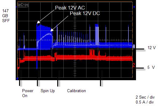
41 9.0 DC Power Requirements The following voltage specification applies at the drive power connector. Connections to the drive should be made in a safety extra low voltage (SELV) circuit. There is no power on or power off sequencing requirement. Adequate secondary over-current protection is the responsibility of the system. Table 16: Input Voltage and Capacitance Supply Tolerance Absolute Max Spike Voltage Supply Rise Time Capacitance 5 V +/- 5% 5.5 V ms 104 uf 12 V +/- 5% 15 V ms 60 uf Note: -8% is acceptable during spin up, but the spin up time is not guaranteed. 9.1 Power Supply Current, Average and Peak The following current and power requirements are typical when operating under the following conditions: Nominal 5 and 12V, Background Media Scan (BMS) disabled for Idle, Write Caching disabled and the drive reporting a temperature of 45C 25
42 26
43 9.2 Ripple Voltage Table 17: Power Supply Generated Ripple at Drive Power Connector Maximum (mv pp) MHz +5 V DC V DC During drive start up and seek, 12 volt ripple is generated by the drive (referred to as dynamic loading). If the power of several drives is daisy chained, the power supply ripple plus other drive dynamic loading must remain within the regulation tolerance of +5%. A common supply with separate power leads to each drive is a more desirable method of power distribution. To prevent external electrical noise from interfering with the drive's performance, the drive must be held by four screws in a user system frame that has no electrical level difference at the four screw positions. The drive enclosure must not be used in the current return path of the drive power supply. The maximum common-mode noise current passing through the drive must not exceed 20 ma. 9.3 Power Consumption Efficiency Index Table 18: Power Consumption Efficiency Index Model 147 GB Model 73 GB Model Power Consumption Efficiency Index -Idle Mode (W/GB)
44 28
45 10.0 Reliability 10.1 Start/Stop Cycles The drive is designed to withstand a minimum of 50,000 start/stop cycles at ambient environment. The drive is designed to withstand a minimum of 10,000 start/stop cycles at the operating environment conditions specified in Chapter 8.0, Environment on page Load/Unload Cycles The drive is designed to withstand a minimum of 200,000 load/unload cycles at the operating environmental conditions specified in Chapter 8.0, Environment on page Data Reliability The probability of an uncorrectable data error is 1 in 1x10 16 bits read. ECC implemention: 1 symbol = 10 bits 1 interleaves 16 symbols, On-The-Fly correction Up to 30 symbols (total) Off-Line correction with burst error information LBA seeded 32 bit CRC for ECC miscorrect detection 10.4 Seek errors A non-recoverable seek/id miscompare error is defined as a seek operation that cannot be recovered by the error recovery procedure of the drive. The drive reports sense key 04 and sense code 02 for this error. No drive has more than one non-recoverable seek/id miscompare error per 100 million seek operations (1 in 1x 10 8 ) when operated at the full range of voltage and environmental conditions Failure prediction (S.M.A.R.T) A recoverable equipment error is an error other than a seek/id miscompare error or read error that is detected and corrected by the drive error recovery procedure. Examples are Write Fault, Drive Not Ready and internal drive errors. SMART Monitoring Parameters are checked to determine if the (Read/Write/Seek) error rates exceed the drive s threshold value when an error occurs and a minimum amount of operation has been completed. A check is also performed for a minimum level of Spare Sector Availability. The Head Load / Unload Count, Spin Up Time and Spin Up Retry Count parameters are checked prior to reporting a Ready condition at Power On. Non-recoverable equipment errors indicate a defective drive MTBF (Mean Time Between Failure): 1.6M hours. This MTBF target is based on a sample population and is estimated by statistical measurements and acceleration algorithms under nominal operating conditions. MTBF ratings are not intended to predict an individual drive s reliability. MTBF does not constitute a warranty. 29
46 10.7 Preventive Maintenance None Temperature Warning Temperature Warning is enabled by setting the EWASC (Enable Warning Additional Sense Code) bit to 1 and setting DEXCPT (Disable Exception Control) bit to 0 in Mode Page 1C. For mode page settings, refer to Section Mode Page 1C (Informational Exceptions Control) on page 159. The warning is issued as sense data (Sense Key 01h, Code 0Bh, Qual 01h). The drive temperature is reported in Log Sense page 2F. Refer to Section Log Sense Page 18 on page
47 11.0 Mechanical Specifications 11.1 Outline 11.2 Mechanical Dimensions The drive complies with SFF Table 19: Physical Dimensions Height [mm] 14.8 ± 0.2 Width [mm] 70 ± 0.1 Length (base) [mm] ± 0.15 Length (including connector) [mm] ± 0.7 Weight [grams - maximum] 147 GB Model 225 grams 73 GB Model 218 grams 31

48 32
49 11.3 Interface Connector The interface conforms to the specification SFF-8223, 2.5 Drive Form Factor with Serial Connector. 33
50 11.4 Mounting Positions and Tappings 34
51 11.5 Drive Mounting The drive will operate in all axes (6 directions). Performance and error rate will stay within specification limits if the drive is operated in the other orientations from which it was formatted. The reccommended mounting screw torque is 0.45 Nm (4.5 Kgf-cm). The recommended mounting screw depth is 2.5 mm maximum for bottom and 3.0 mm maximum for horizontal mounting. To avoid performance degradation, mount the drive in the system securely enough to prevent excessive motion or vibration of the drive at seek operation or spindle rotation, using appropriate screws or equivalent mounting hardware. Consult with the issuer of this specification for actual application if necessary. Drive level vibration tests and shock tests are to be conducted with the drive mounted to a table using the bottom four screws Heads Unload and Actuator Lock Heads are moved out from the disks (unload) to protect the disk data during shipping, moving or storage. At power down, the heads are automatically unloaded from over the disk area and the head actuator locking mechanism will secure the heads in the unload position. 35
52 36
53 12.0 Vibration and Shock All vibration and shock measurements in this section are made with a bare drive. The input for the measurements are applied to the normal drive mounting points unless noted otherwise Operating Vibration Random Vibration The drive is designed to operate without unrecoverable errors while being subjected to the vibration levels as defined below. The assessments are carried out during 30 minutes of random vibration using the power spectral density (PSD) levels as follows. No Errors: 0.4 G RMS, Hz, flat PSD profile for each of the three mutually perpendicular axes. No Data Loss: 1.2 G RMS, Hz, flat PSD profile for each of the three mutually perpendicular axes. No Data Loss: 1.5 G RMS, Hz for each of the three mutually perpendicular axes. Note: The specified levels are measured at the mounting points Swept Sine Vibration The drive will meet the criterion while operating in the respective conditions as described below. No errors: Hz sine wave, 0.5 octave/minute sweep rate No data loss: Hz sine wave, 0.5 octave/minute sweep rate 12.2 Non-operating Vibrations The drive will not sustain permanent damage or loss of recorded data after being subjected to the environments as described below Random Vibration The test consists of a random vibration applied for each of the three mutually perpendicular axes. A time duration of ten minutes per axis G RM S, Hz, flat PSD profile Swept Sine Vibration The test consists of a swept sine vibration applied for each of the three mutually perpendicular axes. 2.5 G 0-peak, Hz sine wave, 0.5 octave/minute sweep rate Operating shock The drive will meet the criterion while operating in the respective conditions as described below. No data loss: No data loss: 15G, 11 ms duration, half sinewave shock pulse 60G, 2 ms duration, half sinewave shock pulse The shock pulses of each level are applied to the drive, ten pulses for each direction and for all three mutually perpendicular axes. There must be a minimum of thirty seconds delay between shock pulses. The input level is applied to a base plate where the drive is attached using four mounting screws. 37
54 12.4 Non-operating shock The drive will not sustain permanent damage or loss of recorded data after being subjected to the environments as described below Half sinewave shock pulse 100 G, 11 ms duration, half sinewave pulse 300 G, 2 ms duration, half sine wave pulse 200 G, 0.5 ms duration, half sinewave pulse The shocks are applied in each direction of the drive for the three mutually perpendicular axes, one axis at a time. The input level is applied to a base plate where the drive is attached using four mounting screws Rotational shock 30,000 radians /second 2, 1 ms duration 20,000 radians /second 2, 2 ms duration The shock input is applied around the axis of the actuator pivot. The shock input does not displace the heads from the actuator latched position. 38
55 13.0 Acoustics 13.1 Sound power levels The upper limit criteria of A-weighted sound power levels are given in Bel, relative to one pico watt, and are shown in the following table. The measurement method is in accordance with ISO Table 20: A-weighted sound power levels Model Mode A-weighted sound power level (Bel) Typical Maximum 147 GB Idle Background power levels of the acoustic test chamber for each octave band are to be recorded. Sound power levels are measured with the drive supported by spacers so that the lower surface of the drive is located at a height of 25 cm from the chamber floor. No sound-absorbing material shall be used. The acoustical characteristics of the drive subsystem are measured under the following conditions. Idle Mode: Powered on, disks spinning, track following, unit ready to receive and respond to host commands. Operating Mode Continuous random cylinder selection and seek operation of the actuator with dwell time at each cylinder. Seek rate for the drive is calculated per the formula below: Ns = average seek rate in seeks/sec where: Ns = 0.4 / (Tt + Tl) Tt = published random seek time Operating GB Idle Operating Tl = time for the drive to rotate by half a revolution 39
56 40
57 14.0 Identification 14.1 Labels The following labels are affixed to every hard disk drive shipped from the drive manufacturing location in accordance with appropriate hard disk drive assembly drawing: A label containing Hitachi Global Storage Technologies logo, Hitachi part number and the statement Made by Hitachi, or Hitachi approved equivalent. A label containing drive model number, manufacturing date, formatted capacity, country of origin or Hitachi approved equivalent and UL, C-UL, TUV, CE, MIC, BSMI,CTICK, RoHS and Recycle logos. A bar code label containing the drive serial number. A user designed label, per agreement Interface definition mark, SAS-3 Model The labels may be integrated with other labels. 41
58 42
59 15.0 Electromagnetic Compatibility The drive, when installed in a suitable enclosure and exercised with a random accessing routine at a maximum data rate will comply with the worldwide EMC requirements listed below. The drive is designed for system integration and installation into a suitable enclosure for use. As such, the drive is supplied as a subassembly and is not subject to Subpart B of Part 15 of the FCC Rules and Regulations. The design of the drive serves to minimize radiated emissions when installed in an enclosure that provides reasonable shielding. As such, the drive is capable of meeting FCC Class B limits. However, it is the users responsibility to assure that the drive meets the appropriate EMC requirements in their system. Shielded I/O cables may be required if the enclosure does not provide adequate shielding, with the shields grounded to the enclosure and to the host computer. Radiated and Conducted EMI CISPR22 AS/NZS CISPR22 CNS13438 (Taiwan) EN55022 (EU)* FCC Title47 Part 15 (USA) GB9254 (China) ICES-003, Issue 4 VCCI (Japan) Class B Class B Class B Class B Class B Class B Class B Class B ITE Immunity EN55024* Power Line Harmonics EN (EU) GB (China) Voltage Fluctuations and Flicker EN (EU) GB (China) * Details are included in the Agency Compliance Report Class B Regulatory Notices European Union This product is in conformity with the protection requirements of EU Council Directive 2004 / 108 / EC on the approximation of the laws of the Member States relating to electromagnetic compatibility. Hitachi cannot accept responsibility for any failure to satisfy the protection requirements resulting from a non-recommended modification of the product, including the fitting of non-hitachi option cards. This product has been tested and found to comply with the limits for Class B Information Technology Equipment according to 43
60 European Standard EN The limits for Class B equipment were derived for typical residential environments to provide reasonable protection against interference with licensed communication devices. Canada This Class B digital apparatus complies with Canadian ICES-003. Cet appareil numérique de la classe B est conforme à la norme NMB-003 du Canada. Germany Deutschsprachiger EU Hinweis: Hinweis für Geräte der Klasse B EU-Richtlinie zur Elektromagnetischen Verträglichkeit Dieses Produkt entspricht den Schutzanforderungen der EU-Richtlinie 89/336/EWG zur Angleichung der Rechtsvorschriften über die elektromagnetische Verträglichkeit in den EU-Mitgliedsstaaten. und hält die Grenzwerte der EN Klasse B ein. Um dieses sicherzustellen, sind die Geräte wie in den Handbüchern beschrieben zu installieren und zu betreiben. Des Weiteren dürfen auch nur von der HITA- CHI empfohlene Kabel angeschlossen werden. HITACHI übernimmt keine Verantwortung für die Einhaltung der Schutzanforderungen, wenn das Produkt ohne Zustimmung der HITACHI verändert bzw. wenn Erweiterungskomponenten von Fremdherstellern ohne Empfehlung der HITACHI gesteckt/eingebaut werden. Deutschland: Einhaltung des Gesetzes über die elektromagnetische Verträglichkeit von Geräten Dieses Produkt entspricht dem "Gesetz über die elektromagnetische Verträglichkeit von Geräten (EMVG)". Dies ist die Umsetzung der EU-Richtlinie 89/336/EWG in der Bundesrepublik Deutschland. Zulassungsbescheinigung laut dem Deutschen Gesetz über die elektromagneti-sche Verträglichkeit von Geräten (EMVG) vom 18. September 1998 (bzw. der EMC EG Richtlinie 89/336) für Geräte der Klasse B Dieses Gerät ist berechtigt, in Übereinstimmung mit dem Deutschen EMVG das EG-Konformitätszeichen - CE - zu führen. Verantwortlich für die Konformitätserklärung nach Paragraf 5 des EMVG ist die Hitachi Global Storage Technologies, 3403 Yerba Buena Road San Jose, CA Informationen in Hinsicht EMVG Paragraf 4 Abs. (1) 4: Das Gerät erfüllt die Schutzanforderungen nach EN und EN Klasse B. Korea (MIC) Taiwan (BSMI) 44
61 16.0 Standards The following shows the safety standards for different countries UL and C-UL Standard Conformity The drive is qualified per ULIEC : 2001, First Edition for use in Information Technology Equipment, including Electric Business Equipment. The UL recognition, or the C-UL certification, is maintained for the product life. The UL and C-UL recognition mark appears on the drive European Standards Compliance The product is certified to the following: EN :2001, First Edition. EN 55022: A1:2007 (Class B ) EN 55024: A1:2001 +A2:2003 EN : 2006 EN : Al: A2: German Safety Mark The product is approved by TUV on Test requirement:en :2001, First Edition, but the GS mark is not applicable to internal devices such as these drives Flammability The printed wiring boards, flex cables, and connectors used in this drive meet or exceed the UL minimum flamability classifications listed in the table below. The flamability ratings are marked on the printed wiring boards and flex cables. Component Flamability Rating Rigid Printed Wiring Board Min. V-1 Flex Cable - no components Min. V-2 Flex Cable with components Min. V-1 Interface & motor connectors Min. V-2 Serial Connector Min. V Corporate Standards Compliance This product has been designed to meet the following Corporate Standards: - NB Product Safety, National Requirements-All Countries. - CS Electrical, Mechanical and Flammability - NB Product Safety National Certification Conformity Requirement - CS Eco-Product Design Requirement 45
62 46
.")
63 17.0 SAS Attachment This section defines some basic terminology and describes the behavior of the drive when attached to a Serial Attached Scsi (i.e. SAS) domain General This section introduces some of the terminology that is used in describing Serial Attached SCSI (i.e. SAS). SAS is logically a bi-directional, point to point serial data channel that leverages the Scsi protocol set. Nodes are physically connected via a Port. Ports may be connected point-to-point via SAS expanders, to form a complex switching network, referred to as a SAS domain. SAS is defined in terms of a hierarchy of functions or 'protocol layers'. This discussion will focus in on the aspects of SAS that are relevent to this product. SCSI Application Layer - Clause 10 SSP Transport Layer (Serial SCSI Protocol) - Clause 9 SAS Port Layer - Clause 8 SSP Link Layer - Clause 7 SAS PHY Layer - Clause 6 SAS Physical Layer - Clause 5 All layers are defined in the following ANSI standard. "Serial Attached SCSI - 2 (SAS-2)" In addition, this drive claims compliance with the following ANSI standards. SCSI Architecture Model (SAM-3) SCSI Block Commands (SBC2) 17.2 SAS Features The following SAS features are supported by the Drive. SAS Compliance - "Serial Attached SCSI - 2 (SAS-2)" SAS Protocol - This drive supports Serial Scsi Protocol (SSP). - STP (Tunneled SATA) and SMP (Management protocol) protocols are NOT supported. SAS Dual Ported Operation - single PHY ports (i.e. Narrow port. Wide Port NOT supported) - ports function independently with separate firmware controls - Multiple DMA engines capable of accessing either port - full duplex and dual port DMA data/data operations - Maximum outstanding credit of four per port 47
Hard Disk Drive Specification Ultrastar C10K inch Serial Attached SCSI (SAS) Hard Disk Drive HUC106045CSS600 HUC106030CSS600. Version: 3.
 Hard Disk Drive HUC106045CSS600 HUC106030CSS600. Version: 3.") Hard Disk Drive Specification Ultrastar C10K600 2.5 inch Serial Attached SCSI (SAS) Hard Disk Drive Models: HUC106060CSS600 HUC106045CSS600 HUC106030CSS600 Version: 3.0 19 November 2012 Warning: Printed
Hard Disk Drive Specification Ultrastar C10K600 2.5 inch Serial Attached SCSI (SAS) Hard Disk Drive Models: HUC106060CSS600 HUC106045CSS600 HUC106030CSS600 Version: 3.0 19 November 2012 Warning: Printed
Hard Disk Drive Specification Ultrastar C7K1000 Version: May 2014
 Hard Disk Drive Specification Ultrastar C7K1000 2.5 inch Serial Attached SCSI (SAS) Hard Disk Drive Models: HUC721010ASS600 HUC721010ASS601(Encrypt) Version: 1.1 26 May 2014 Warning: Printed copies of
IBM OEM Storage Products WDS 3100/3200 FEATURES ========
 IBM OEM Storage Products WDS 3100/3200 FEATURES ======== - 108/216MB formatted capacity(512 bytes/sector) - Industry standard interface: ANSI/SCSI-2 - Integrated controller - Logical block addressing (LBA)
Solid State Drive Specification Ultrastar SSD800M/1000M. 2.5" Serial Attached SCSI (SAS) Solid State Drive HUSMH8080ASS201 HUSMM8020ASS205
 Solid State Drive HUSMH8080ASS201 HUSMM8020ASS205") Solid State Drive Specification Ultrastar SSD800M/1000M 2.5" Serial Attached SCSI (SAS) Solid State Drive Models: HUSMH8080ASS200 HUSMH8080ASS201 HUSMH8080ASS204 HUSMH8080ASS205 HUSMH8040ASS200 HUSMH8040ASS201
Solid State Drive Specification Ultrastar SSD800M/1000M 2.5" Serial Attached SCSI (SAS) Solid State Drive Models: HUSMH8080ASS200 HUSMH8080ASS201 HUSMH8080ASS204 HUSMH8080ASS205 HUSMH8040ASS200 HUSMH8040ASS201
DCAS / DCAS SCSI-3 FAST-20 50/68/80-pin
 S73H-7993-03 OEM HARD DISK DRIVE SPECIFICATIONS for DCAS-34330 / DCAS-32160 SCSI-3 FAST-20 50/68/80-pin 3.5-Inch Hard Disk Drive ( 4330 / 2160 MB ) Revision (1.2) S73H-7993-03 OEM HARD DISK DRIVE SPECIFICATIONS
Hard disk drive specifications Ultrastar He 12
 Hard disk drive specifications Ultrastar He 12 3.5 inch Serial Attached SCSI hard disk drive Models: HUH721212AL5200/1/4/5 HUH721212AL4200/1/4/5 Revision 1.0 12 August 2017 1 Publication Disclaimer Information
DORS / DORS-32160
 S39H-2859-03 OEM HARD DISK DRIVE SPECIFICATIONS for DORS-31080 / DORS-32160 SCSI-3 FAST-20 68-pin Single-ended Models 3.5-Inch Hard Disk Drive ( 1080 / 2160 MB ) Revision (3.0) S39H-2859-03 OEM HARD DISK
Hard disk drive specifications Ultrastar DC HC510 (previously known as Ultrastar He10) 3.5 inch Serial Attached SCSI hard disk drive
 3.5 inch Serial Attached SCSI hard disk drive") Hard disk drive specifications Ultrastar DC HC510 (previously known as Ultrastar He10) 3.5 inch Serial Attached SCSI hard disk drive Models: HUH721010AL5200/1/4/5 HUH721008AL5200/1/4/5 HUH721010AL4200/1/4/5
Hard disk drive specifications Ultrastar DC HC510 (previously known as Ultrastar He10) 3.5 inch Serial Attached SCSI hard disk drive Models: HUH721010AL5200/1/4/5 HUH721008AL5200/1/4/5 HUH721010AL4200/1/4/5
Hard Disk Drive Specification
 Hard Disk Drive Specification Ultrastar 15K450 3.5 inch 4Gb FC-AL Hard Disk Drive Models: HUS154545VLF400 HUS154530VLF400 Version 1.2 29 October 2008 Warning: Printed copies of this document are considered
IBM OEM STORAGE PRODUCTS WDA S260 & 2120
 FEATURES IBM OEM STORAGE PRODUCTS WDA S260 & 2120 63/126MB formatted capacity (512 bytes/sector) AT standard interface- Integrated controller IBM PC-AT Task File Architecture 1:1 interleave 1,7 Run-Length
Product summary Hitachi 3K4 Microdrive CF+ Type II
 Product summary Hitachi 3K4 Microdrive CF+ Type II Models: HMS360404D5CF00 HMS360402D5CF00 Introduction The Hitachi 3K4 Microdrive comes in capacities of 4 GB and 2 GB. Developed to meet the needs of handheld
IBM OEM STORAGE PRODUCTS WDA L80 & L160
 FEATURES IBM OEM STORAGE PRODUCTS WDA L80 & L160 85/171MB formatted capacity (512 bytes/sector) AT standard interface- Integrated controller 1:1 interleave 1,7 Run-Length Limited (RLL) encoding 32KB Read
Disk. Zone 7 (Inner) Data tracks per surface: Data sectors per track: Data bytes per track: Zone 3. Zone 4
 Data tracks per surface: Data sectors per track: Data bytes per track: Zone 3. Zone 4") return to original page HP SureStore Disks C2244, C2245, C2246, and C2247 - Technical Specifications In this document: HP SureStore Disks C2244, C2245, C2246, and C2247 technical specifications Table of
return to original page HP SureStore Disks C2244, C2245, C2246, and C2247 - Technical Specifications In this document: HP SureStore Disks C2244, C2245, C2246, and C2247 technical specifications Table of
ibm Product summary IBM Microdrive CF+ Type II IBM storage products Models: DSCM DSCM DSCM Introduction Applications
 ibm Product summary IBM Microdrive CF+ Type II Models: DSCM-000 DSCM-052 DSCM-0340 Introduction The IBM Microdrive comes in capacities of GB, 52 MB, and 340 MB. Developed to meet the needs of handheld
Solid State Drive Specification Ultrastar SSD400S. 3.5" 4Gb FC-AL Solid State Drive Models: HUSSL4040ALF400 HUSSL4020ALF400 HUSSL4010ALF400
 Solid State Drive Specification Ultrastar SSD400S 3.5" 4Gb FC-AL Solid State Drive Models: HUSSL4040ALF400 HUSSL4020ALF400 HUSSL4010ALF400 Version: 2.00 05 October 2012 Warning: Printed copies of this
Ultrastar 2ES DCAS and DCAS 34330
 IBM OEM Storage Products Ultrastar 2ES DCAS 32160 and DCAS 34330 Models: SCSI-3 FAST20 (50pin Single-Ended) SCSI-3 FAST20 wide (68pin Single-Ended) SCSI-3 FAST20 wide (80pin Single-Ended) The performance
Solid State Drive Specification Ultrastar SSD400M. 2.5" Serial Attached SCSI (SAS) Solid State Drive HUSML4020ASS601. Version: 2.0.
 Solid State Drive HUSML4020ASS601. Version: 2.0.") Solid State Drive Specification Ultrastar SSD400M 2.5" Serial Attached SCSI (SAS) Solid State Drive Models: HUSML4040ASS601 HUSML4020ASS601 Version: 2.0 21 September 2012 Warning: Printed copies of this
Solid State Drive Specification Ultrastar SSD400M 2.5" Serial Attached SCSI (SAS) Solid State Drive Models: HUSML4040ASS601 HUSML4020ASS601 Version: 2.0 21 September 2012 Warning: Printed copies of this
Addendum to hard disk drive specifications Hitachi Deskstar 120 GXP 3.5 inch Ultra ATA/100 hard disk drive
 Addendum to hard disk drive specifications Hitachi Deskstar 120 GXP 3.5 inch Ultra ATA/100 hard disk drive Models: IC35L020AVVA07 IC35L040AVVA07 Revision 1.0 13 January 2003 S07N-8418-00 Publication #
3SE4 Series. Customer Approver. Innodisk Approver. Customer: Customer Part Number: Innodisk Part Number: Innodisk Model Name: Date:
 3SE4 Series Customer: Customer Part Number: Innodisk Part Number: Innodisk Model Name: Date: Innodisk Approver Customer Approver Table of contents LIST OF FIGURES... 6 1. PRODUCT OVERVIEW... 7 1.1 INTRODUCTION
3MG2-P Series. Customer Approver. Innodisk Approver. Customer: Customer Part Number: Innodisk Part Number: Innodisk Model Name: Date:
 3MG2-P Series Customer: Customer Part Number: Innodisk Part Number: Innodisk Model Name: Date: Innodisk Approver Customer Approver Table of Contents 1.8 SATA SSD 3MG2-P LIST OF FIGURES... 6 1. PRODUCT
Solid State Drive Specification Ultrastar SSD400S.B. 2.5" Serial Attached SCSI (SAS) Solid State Drive HUSSL4020BSS600 HUSSL4010BSS600. Version: 2.
 Solid State Drive HUSSL4020BSS600 HUSSL4010BSS600. Version: 2.") Solid State Drive Specification Ultrastar SSD400S.B 2.5" Serial Attached SCSI (SAS) Solid State Drive Models: HUSSL4040BSS600 HUSSL4020BSS600 HUSSL4010BSS600 Version: 2.00 21 September 2012 Warning: Printed
Solid State Drive Specification Ultrastar SSD400S.B 2.5" Serial Attached SCSI (SAS) Solid State Drive Models: HUSSL4040BSS600 HUSSL4020BSS600 HUSSL4010BSS600 Version: 2.00 21 September 2012 Warning: Printed
Data transfer rate - Max sustained 61.4 MB/s. Acoustics (idle) 3.1 bels. 9.0 W PATA Non-operational shock 225 G. Disks / Heads 5 / 10
 3.1 bels. 9.0 W PATA Non-operational shock 225 G. Disks / Heads 5 / 10") Feature Set Description Hitachi Deskstar 7K400 Ultra ATA/133 Hard disk drive Models HDS724040KLAT80 Introduction The Deskstar 7K400 was designed for a variety of capacity intensive applications. At launch
Feature Set Description Hitachi Deskstar 7K400 Ultra ATA/133 Hard disk drive Models HDS724040KLAT80 Introduction The Deskstar 7K400 was designed for a variety of capacity intensive applications. At launch
Hard Drive: MINISCRIBE: M MB 5.25"/HH MFM ST506
 Hard Drive: MINISCRIBE: M3425 20MB 5.25"/HH MFM ST506 M 3 4 2 5 MINISCRIBE NO MORE PRODUCED Native Translation ------+-----+-----+----- Form 5.25"/HH Cylinders 615 Capacity form/unform 20/ 25 MB Heads
Rhino Buffer Module PSM24-BFM600S. Operating Instructions
 Rhino Buffer Module PSM24-BFM600S Operating Instructions RHINO BUFFER MODULE PSM24-BFM600S Description The PSM24-BFM600S Buffer Module will hold the output voltage of a 24 VDC power supply after brownouts
OEM HARD DISK DRIVE SPECIFICATIONS. for DPRS-20810/21215 (810/1215 MB) 2.5-Inch Hard Disk Drive with SCSI Interface
 2.5-Inch Hard Disk Drive with SCSI Interface") OEM HARD DISK DRIVE SPECIFICATIONS S39H-4500-02 for DPRS-20810/21215 (810/1215 MB) 2.5-Inch Hard Disk Drive with SCSI Interface Revision (1.2) OEM HARD DISK DRIVE SPECIFICATIONS S39H-4500-02 for DPRS-20810/21215
OEM HARD DISK DRIVE SPECIFICATIONS S39H-4500-02 for DPRS-20810/21215 (810/1215 MB) 2.5-Inch Hard Disk Drive with SCSI Interface Revision (1.2) OEM HARD DISK DRIVE SPECIFICATIONS S39H-4500-02 for DPRS-20810/21215
3MG2-P Series. Customer Approver. Approver. Customer: Customer Part Number: Innodisk Part Number: Model Name: Date:
 3MG2-P Series Customer: Customer Part Number: Innodisk Part Number: Innodisk Model Name: Date: Innodisk Approver Customer Approver Table of Contents 1.8 SATA SSD 3MG2-P LIST OF FIGURES... 6 1. PRODUCT
Advantech. AQS-I42N I Series. Semi-Industrial Temperature. Datasheet. SATA III 6Gb/s M.2 SSD Semi-Industrial Temp AQS-I42N I series
 Advantech AQS-I42N I Series erature Datasheet Rev. 2.0 2015-09-13 1 AQS-I42N I Series Features SATA III 6Gb/s M.2 SSD I Series Offers industrial level M.2 SSD that sustains and extends system lifecycle
3MG2-P Series. Customer Approver. Innodisk Approver. Customer: Customer Part Number: Innodisk Part Number: Innodisk Model Name: Date:
 3MG2-P Series Customer: Customer Part Number: Innodisk Part Number: Innodisk Model Name: Date: Innodisk Approver Customer Approver Table of contents 2.5 SATA SSD 3MG2-P LIST OF FIGURES... 6 1. PRODUCT
3ME3 Series. Customer Approver. Innodisk Approver. Customer: Customer Part Number: Innodisk Part Number: Innodisk Model Name: Date:
 3ME3 Series Customer: Customer Part Number: Innodisk Part Number: Innodisk Model me: Date: Innodisk Approver Customer Approver Table of contents 2.5 SATA SSD 3ME3 LIST OF FIGURES... 6 1. PRODUCT OVERVIEW...
SATA III 6Gb/S 2.5 SSD Industrial Temp AQS-I25S I Series. Advantech. Industrial Temperature. Datasheet. Rev
 Advantech erature Datasheet Rev. 3.0 2015-09-22 1 Features SATA III 6Gb/s SSD Advanced Global Wear-Leveling and Block management for reliability I Series Offers industrial level SSD that sustains and extends
3ME Series. Customer Approver. Approver. Customer: Customer Part Number: Innodisk Part Number: Model Name: Date:
 3ME Series Customer: Customer Part Number: Innodisk Part Number: Innodisk Model Name: Date: Innodisk Approver Customer Approver Table of contents 2.5 SATA SSD 3ME LIST OF FIGURES... 6 1. PRODUCT OVERVIEW...
HP SSD S700 Series. Product Specification Capacity: 120GB, 250GB, 500GB Components: 3D TLC NAND Flash
 HP SSD S700 Series Product Specification Capacity: 120GB, 250GB, 500GB Components: 3D TLC NAND Flash Read and Write IOPS (Iometer* Queue Depth 32) 120 GB Random 4 KB reads: Up to 71 K IOPS Random 4 KB
Solid State Drive Specification Ultrastar SSD400S. 2.5" Serial Attached SCSI (SAS) Solid State Drive HUSSL4020ASS600 HUSSL4010ASS600. Version: 2.
 Solid State Drive HUSSL4020ASS600 HUSSL4010ASS600. Version: 2.") Solid State Drive Specification Ultrastar SSD400S 2.5" Serial Attached SCSI (SAS) Solid State Drive Models: HUSSL4040ASS600 HUSSL4020ASS600 HUSSL4010ASS600 Version: 2.0 21 September 2012 Warning: Printed
Solid State Drive Specification Ultrastar SSD400S 2.5" Serial Attached SCSI (SAS) Solid State Drive Models: HUSSL4040ASS600 HUSSL4020ASS600 HUSSL4010ASS600 Version: 2.0 21 September 2012 Warning: Printed
3ME4 Series. Customer Approver. Innodisk Approver. Customer: Customer Part Number: Innodisk Part Number: Innodisk Model Name: Date:
 3ME4 Series Customer: Customer Part Number: Innodisk Part Number: Innodisk Model Name: Date: Innodisk Approver Customer Approver Table of contents LIST OF FIGURES... 6 1. PRODUCT OVERVIEW... 7 1.1 INTRODUCTION
3ME3 Series. Customer Approver. Innodisk Approver. Customer: Customer Part Number: Innodisk Part Number: Innodisk Model Name: Date:
 3ME3 Series Customer: Customer Part Number: Innodisk Part Number: Innodisk Model Name: Date: Innodisk Approver Customer Approver Table of contents SATA Slim 3ME3 LIST OF FIGURES... 6 1. PRODUCT OVERVIEW...
3MG-P Series. Customer Approver. Innodisk Approver. Customer: Customer Part Number: Innodisk Part Number: Innodisk Model Name: Date:
 3MG-P Series Customer: Customer Part Number: Innodisk Part Number: Innodisk Model Name: Date: Innodisk Approver Customer Approver Table of contents LIST OF FIGURES... 6 1. PRODUCT OVERVIEW... 7 1.1 INTRODUCTION
3ME2 Series. Customer Approver. Innodisk Approver. Customer: Customer Part Number: Innodisk Part Number: Innodisk Model Name: Date:
 3ME2 Series Customer: Customer Part Number: Innodisk Part Number: Innodisk Model Name: Date: Innodisk Approver Customer Approver Table of contents 2.5 SATA SSD 3ME2 LIST OF FIGURES... 6 1. PRODUCT OVERVIEW...
3SE Series. Customer Approver. Innodisk Approver. Customer: Customer Part Number: Innodisk Part Number: Innodisk Model Name: Date:
 3SE Series Customer: Customer Part Number: Innodisk Part Number: Innodisk Model Name: Date: Innodisk Approver Customer Approver Table of contents SATADOM-SV 3SE LIST OF FIGURES... 6 1. PRODUCT OVERVIEW...
INTERFACE SPECIFICATION GB - SCSI INCH DRIVE RELEASE 6.01
 INTERFACE SPECIFICATION 0664 2.0 GB - SCSI - 3.5 INCH DRIVE RELEASE 6.01 July 12, 1994 Page 1 of 297 Page 1 of 297 Preface 0664 S10 FUNCTIONAL FEATURES "On the Fly" error correction capabilities LRC protection
3MR-P Series. Customer Approver. Approver. Customer: Customer Part Number: Innodisk Part Number: Model Name: Date:
 3MR-P Series Customer: Customer Part Number: Innodisk Part Number: Innodisk Model Name: Date: Innodisk Approver Customer Approver Table of Contents LIST OF FIGURES... 6 1. PRODUCT OVERVIEW... 7 1.1 INTRODUCTION
HP SSD EX900 M.2. Product Specification Capacity: 120GB, 250GB, 500GB Components: 3D NAND TLC
 HP SSD EX900 M.2 Product Specification Capacity: 120GB, 250GB, 500GB Components: 3D NAND TLC Read and Write IOPS (Iometer* Queue Depth 32) 120 GB Random 4 KB reads: Up to 110 K IOPS Random 4 KB writes:
Model: Z1DA-78A. 3.5 Micro Floppy Disk Drive. Specification
 Model: Z1DA-78A 3.5 Micro Floppy Disk Drive Specification Citizen Systems Europe Park House, 643 651 Staines Road, Feltham. TW14 8PA. Tel: +44 20 8893 1900 www.citizen.co.uk Table of Contents TABLE OF
1MG3-P Series. Customer Approver. Innodisk Approver. Customer: Customer Part Number: Innodisk Part Number: Innodisk Model Name: Date:
 1MG3-P Series Customer: Customer Part Number: Innodisk Part Number: Innodisk Model Name: Date: Innodisk Approver Customer Approver Table of contents 2.5 PATA SSD 1MG3-P LIST OF FIGURES... 6 1. PRODUCT
LIMITS IV. PRIAM DISKOS 3350!6650!i5450 WINCHESTER DISC DRIVE PRODUCT SPECIFICATION PAGE INTRODUCTION
 PRIAM DISKOS 3350!6650!i5450 WINCHESTER DISC DRIVE PRODUCT SPECIFICATION I. II. III. INTRODUCTION A. General Description B. Design Advantages C. Product Options and Accessories D. Reference Documentation
HP SSD EX920 M.2. 2TB Sustained sequential read: Up to 3200 MB/s Sustained sequential write: Up to 1600 MB/s
 HP SSD EX920 M.2 Product Specification Capacity: 256GB, 512GB, 1TB, 2TB Components: 3D NAND/ DRAM Cache Read and Write IOPS (Iometer* Queue Depth 32) 256 GB Random 4 KB reads: Up to 180K IOPS Random 4
3SR-P Series. Customer Approver. Innodisk Approver. Customer: Customer Part Number: Innodisk Part Number: Innodisk Model Name: Date:
 3SR-P Series Customer: Customer Part Number: Innodisk Part Number: Innodisk Model Name: Date: Innodisk Approver Customer Approver Table of Contents LIST OF FIGURES... 6 1. PRODUCT OVERVIEW... 7 1.1 INTRODUCTION
3SR-P Series. Customer Approver. Approver. Customer: Customer Part Number: Innodisk Part Number: Model Name: Date:
 3SR-P Series Customer: Customer Part Number: Innodisk Part Number: Innodisk Model Name: Date: Innodisk Approver Customer Approver Table of Contents LIST OF FIGURES... 6 1. PRODUCT OVERVIEW... 7 1.1 INTRODUCTION
3MG-P Series. Customer Approver. Innodisk Approver. Customer: Customer Part Number: Innodisk Part Number: Innodisk Model Name: Date:
 3MG-P Series Customer: Customer Part Number: Innodisk Part Number: Innodisk Model Name: Date: Innodisk Approver Customer Approver Table of contents msata 3MG-P LIST OF FIGURES... 6 1. PRODUCT OVERVIEW...
3IE Series. Customer Approver. Approver. Customer: Customer Part Number: Innodisk Part Number: Model Name: Date:
 3IE Series Customer: Customer Part Number: Innodisk Part Number: Innodisk Model Name: Date: Innodisk Approver Customer Approver Table of contents SATADOM-MV 3IE LIST OF FIGURES... 6 1. PRODUCT OVERVIEW...
3ME3 Series. Customer Approver. Innodisk Approver. Customer: Customer Part Number: Innodisk Part Number: Innodisk Model Name: Date:
 3ME3 Series Customer: Customer Part Number: Innodisk Part Number: Innodisk Model Name: Date: Innodisk Approver Customer Approver Table of contents msata 3ME3 LIST OF FIGURES... 6 1. PRODUCT OVERVIEW...
Dell MD1280 Storage Enclosure Getting Started Guide
 Dell MD1280 Storage Enclosure Getting Started Guide Regulatory Model: SP-2584, E11J Notes, Cautions, and Warnings NOTE: A NOTE indicates important information that helps you make better use of your computer.
HP SSD S700 M.2. Product Specification Capacity: 120GB, 250GB, 500GB Components: 3D TLC NAND Flash
 HP SSD S700 M.2 Product Specification Capacity: 120GB, 250GB, 500GB Components: 3D TLC NAND Flash Read and Write IOPS (Iometer* Queue Depth 32) 120 GB Random 4 KB reads: Up to 70 K IOPS Random 4 KB writes:
3MG2-P Series. Customer Approver. Innodisk Approver. Customer: Customer Part Number: Innodisk Part Number: Innodisk Model Name: Date:
 3MG2-P Series Customer: Customer Part Number: Innodisk Part Number: Innodisk Model Name: Date: Innodisk Approver Customer Approver Table of contents 1. PRODUCT OVERVIEW... 7 1.1 INTRODUCTION OF INNODISK
Digital Storage Products Model DSP5200 Model DSP5350 Installation Guide. Order Number: EK-DS002-IG. C01
 Digital Storage Products Model DSP5200 Model DSP5350 Installation Guide Order Number: EK-DS002-IG. C01 May 1993 The information in this document is subject to change without notice and should not be construed
Rhino Redundancy Module PSM24-REM360S. Operating Instructions
 Rhino Redundancy Module PSM4-REM360S Operating Instructions RHINO REDUNDANCY MODULE PSM4-REM360S Description With this module and two power supplies of the PSM series (78, 90, 56, 80 and 360 watt models),
3ME3 Series. Customer Approver. Innodisk Approver. Customer: Customer Part Number: Innodisk Part Number: Innodisk Model Name: Date:
 3ME3 Series Customer: Customer Part Number: Innodisk Part Number: Innodisk Model Name: Date: Innodisk Approver Customer Approver Table of contents msata mini 3ME3 LIST OF FIGURES... 6 1. PRODUCT OVERVIEW...
MK6411MAT (HDD2143) 2.5-INCH HARD DISK DRIVE USER MANUAL
 2.5-INCH HARD DISK DRIVE USER MANUAL") TOSHIBA AMERICA INFORMATION SYSTEMS STORAGE DEVICE DIVISION IRVINE, CALIFORNIA MK6411MAT (HDD2143) 2.5-INCH HARD DISK DRIVE USER MANUAL Rev 02 11/2006 CONTENTS Introduction...1 Setup...2 Using the HDD...4
TOSHIBA AMERICA INFORMATION SYSTEMS STORAGE DEVICE DIVISION IRVINE, CALIFORNIA MK6411MAT (HDD2143) 2.5-INCH HARD DISK DRIVE USER MANUAL Rev 02 11/2006 CONTENTS Introduction...1 Setup...2 Using the HDD...4
Intel Storage System JBOD 2000S3 Product Family
 Intel Storage System JBOD 2000S3 Product Family SCSI Enclosure Services Programming Guide SES Version 3.0, Revision 1.8 Apr 2017 Intel Server Boards and Systems Headline
X1DE-31U USB 3.5" Micro Floppy Disk Drive
 USB 3.5" Micro Floppy Disk Drive Features Introduction This material provides the information necessary to interface the X1 series micro floppy disk drives to floppy disk controllers, and provides all
REDUNDANCY MODULE TSP-REM360 AND TSP-REM600
 REDUNDANCY MODULE TSP-REM360 AND TSP-REM600 Operating Instructions Seite 1 Dimensions drawings: TSP-REM360 Weight: 0.882lb Gewicht: 0.40kg Seite 2 Dimensions drawings: TSP-REM600 Bottom view Top view Side
IBM. Setup Instructions. RS/ Model B50 SA
 RS/6000 7046 Model B50 IBM Setup Instructions SA38-0562-00 First Edition (September 1999) The following paragraph does not apply to the United Kingdom or any country where such provisions are inconsistent
3ME4 Series. Customer Approver. Innodisk Approver. Customer: Customer Part Number: Innodisk Part Number: Innodisk Model Name: Date:
 3ME4 Series Customer: Customer Part Number: Innodisk Part Number: Innodisk Model me: Date: Innodisk Approver Customer Approver Table of contents 2.5 SATA SSD 3ME4 LIST OF FIGURES... 6 1. PRODUCT OVERVIEW...
MLC. Mini SATA III Flash Module. HERMES-JI Series. Product Specification APRO MLC MINI SATA III FLASH MODULE
 MLC Mini SATA III Module HERMES-JI Series Product Specification APRO MLC MINI SATA III FLASH MODULE Version 01V2 Document No. 100-xBMSM-JJICTMB March 2016 APRO CO., LTD. Phone: +88628226-1539 Fax: +88628226-1389
3ME4 Series. Customer: Customer Part Number: Innodisk Part Number: Innodisk Model Name: Date: Innodisk Approver. Customer Approver
 3ME4 Series Customer: Customer Part Number: Innodisk Part Number: Innodisk Model Name: Date: Innodisk Approver Customer Approver Table of Contents Slim SSD 3ME4 LIST OF FIGURES... 6 1. PRODUCT OVERVIEW...
3SE-P Series. Customer Approver. Approver. Customer: Customer Part Number: Innodisk Part Number: Model Name: Date:
 3SE-P Series Customer: Customer Part Number: Innodisk Part Number: Innodisk Model Name: Date: Innodisk Approver Customer Approver Table of contents LIST OF FIGURES... 6 1. PRODUCT OVERVIEW... 7 1.1 INTRODUCTION
Silicon Media Limited. C4 2.5 SATA Solid State Drive Specification (7mm & 9mm height compatible) SMSS325MxxxG-C4-x
 SMSS325MxxxG-C4-x") Silicon Media Limited C4 2.5 SATA Specification (7mm & 9mm height compatible) SMSS325MxxxG-C4-x Version 1.2 Document Number: S-12157 ALL RIGHTS ARE STRICTLY RESERVED. ANY PORTION OF THIS PAPER SHALL NOT
Silicon Media Limited C4 2.5 SATA Specification (7mm & 9mm height compatible) SMSS325MxxxG-C4-x Version 1.2 Document Number: S-12157 ALL RIGHTS ARE STRICTLY RESERVED. ANY PORTION OF THIS PAPER SHALL NOT
Hitachi Travelstar 7K500
 Hitachi Global Storage Technologies 7K500 OEM SPECIFICATION Hard Disk Drive Specification Hitachi Travelstar 7K500 2.5 inch SATA hard disk drive Models: HTS725050A9A364 HTS725040A9A364 HTS725032A9A364
2TB DATA SHEET Preliminary
 2TB DATA SHEET Preliminary Features: SATA 3.1 Compliant, - SATA 6.0Gb/s with 3Gb/s and 1.5Gb/s support ATA modes supported - PIO modes 3 and 4 - Multiword DMA modes 0, 1, 2 - Ultra DMA modes 0, 1, 2, 3,
Output Voltage* (nom.)(adjustable)
(adjustable)") Industrial Power Supplies TBLC Series, 6 90 W Low profile case, module depth only 55 mm Suitable for mounting in domestic installation panels Very high efficiency and low standby power -> compliance to
Industrial Power Supplies TBLC Series, 6 90 W Low profile case, module depth only 55 mm Suitable for mounting in domestic installation panels Very high efficiency and low standby power -> compliance to
MK6022GAX (HDD2184) 2.5-INCH HARD DISK DRIVE USER MANUAL
 2.5-INCH HARD DISK DRIVE USER MANUAL") TOSHIBA AMERICA INFORMATION SYSTEMS STORAGE DEVICE DIVISION IRVINE, CALIFORNIA MK6022GAX (HDD2184) 2.5-INCH HARD DISK DRIVE USER MANUAL Rev 02 11/2006 CONTENTS Introduction...1 Setup...2 Using the HDD...4
TOSHIBA AMERICA INFORMATION SYSTEMS STORAGE DEVICE DIVISION IRVINE, CALIFORNIA MK6022GAX (HDD2184) 2.5-INCH HARD DISK DRIVE USER MANUAL Rev 02 11/2006 CONTENTS Introduction...1 Setup...2 Using the HDD...4
3ME Series. Customer Approver. Innodisk Approver. Customer: Customer Part Number: Innodisk Part Number: Innodisk Model Name: Date:
 3ME Series Customer: Customer Part Number: Innodisk Part Number: Innodisk Model Name: Date: Innodisk Approver Customer Approver Table of contents SATADOM-MV 3ME LIST OF FIGURES... 6 1. PRODUCT OVERVIEW...
Customer: Customer Part Number: Innodisk Part Number: Innodisk Model Name: Date: Innodisk Approver. Customer Approver
 Customer: Customer Part Number: Innodisk Part Number: Innodisk Model Name: Date: Innodisk Approver Customer Approver Table of contents CFast 3SE LIST OF FIGURES... 6 1. PRODUCT OVERVIEW... 7 1.1 INTRODUCTION
D115 The Fast Optimal Servo Amplifier For Brush, Brushless, Voice Coil Servo Motors
 D115 The Fast Optimal Servo Amplifier For Brush, Brushless, Voice Coil Servo Motors Ron Boe 5/15/2014 This user guide details the servo drives capabilities and physical interfaces. Users will be able to
Output Voltage* (nom.)(adjustable)
(adjustable)") Industrial Power Supplies TBLC Series, 6 90 W Low profile case, module depth only 59,5mm Suitable for mounting in domestic installation panels Low output ripples and spikes Fully compliance to ECO-Standard
Industrial Power Supplies TBLC Series, 6 90 W Low profile case, module depth only 59,5mm Suitable for mounting in domestic installation panels Low output ripples and spikes Fully compliance to ECO-Standard
Hard Disk Drive Specification Hitachi Travelstar 7K100
 Hard Disk Drive Specification Hitachi Travelstar 7K100 2.5 inch ATA/IDE hard disk drive Model: HTS721010G9AT00 HTS721080G9AT00 HTS721060G9AT00 Revision 1.3 13 July 2006 Hard Disk Drive Specification Travelstar
AL15SEB SERIES ENTERPRISE PEFORMANCE HDD
 AL15SEB SERIES ENTERPRISE PEFORMANCE HDD The 12.0 Gbit/s [1] SAS interface AL15SEB Series Enterprise Performance HDDs provide up to 2.4 TB capacity and 10,500rpm performance with Enterprise-class reliability.
SGI InfiniteStorage 120
 SGI InfiniteStorage 120 Mass Storage Hardware Topics Edition 003 007-4853-003 Proprietary Rights Notices COPYRIGHT 2006, 2007 SGI. All rights reserved; provided portions may be copyright in third parties,
3ME Series. Customer Approver. InnoDisk Approver. Customer: Customer Part Number: InnoDisk Part Number: InnoDisk Model Name: Date:
 3ME Series Customer: Customer Part Number: InnoDisk Part Number: InnoDisk Model Name: Date: InnoDisk Approver Customer Approver Table of contents SATADOM-SV 3ME LIST OF FIGURES... 6 1. PRODUCT OVERVIEW...
EPTDM Features SATA III 6Gb/s msata SSD
 EPTDM Features SATA III 6Gb/s msata SSD Transcend EPTDM series are msata Solid State Drives (SSDs) with high performance and quality Flash Memory assembled on a printed circuit board. These devices feature
Industrial M SATA III NGFF SSD
 Industrial M.2 2242 SATA III NGFF SSD HERMES-G Series Product Specification INDUSTRIAL M.2 2242 SATA III SSD Version 01V0 Document No. 100-xBMDS-JGTL April 2015 APRO CO., LTD. Phone: +88628226-1539 Fax:
3ME2 Series. Customer Approver. Innodisk Approver. Customer: Customer Part Number: Innodisk Part Number: Innodisk Model Name: Date:
 3ME2 Series Customer: Customer Part Number: Innodisk Part Number: Innodisk Model Name: Date: Innodisk Approver Customer Approver Table of contents LIST OF FIGURES... 6 1. PRODUCT OVERVIEW... 7 1.1 INTRODUCTION
Hard Disk Drive Specification Hitachi C3K inch ATA/IDE hard disk drive
 Hitachi Global Storage Technologies C3K80 (PATA) Hard Disk Drive Specification Hard Disk Drive Specification Hitachi C3K80 1.8 inch ATA/IDE hard disk drive Models: HTC368080H8CE00 HTC368060H8CE00 HTC368040H5CE00
3ME3 Series. Customer Approver. InnoDisk Approver. Customer: Customer Part Number: InnoDisk Part Number: InnoDisk Model Name: Date:
 3ME3 Series Customer: Customer Part Number: InnoDisk Part Number: InnoDisk Model Name: Date: InnoDisk Approver Customer Approver Table of contents SATADOM-SH 3ME3 LIST OF FIGURES... 6 1. PRODUCT OVERVIEW...
ATAPI TRAY DVD-ROM DRIVE UNIT
 ATAPI TRAY DVD-ROM DRIVE UNIT DVD-120 PRODUCT SPECIFICATION Revision 1.0 Oct. 30 st, 2002 PIONEER CORPORATION Table of Contents Page Features...3 Name of Parts / Function / Setting...4 Power
Dell PowerVault MD3060e Storage Enclosure Owner's Manual
 Dell PowerVault MD3060e Storage Enclosure Owner's Manual Regulatory Model: E08J Series Regulatory Type: E08J001 Notes, Cautions, and Warnings NOTE: A NOTE indicates important information that helps you
Dell Storage Center. Getting Started Guide. SCv2000 and SCv2020 Storage System. Regulatory Model: E09J, E10J Regulatory Type: E09J001, E10J001
 Dell Storage Center SCv2000 and SCv2020 Storage System Getting Started Guide Regulatory Model: E09J, E10J Regulatory Type: E09J001, E10J001 Notes, Cautions, and Warnings NOTE: A NOTE indicates important
Dell SC7020 Storage Controller Getting Started Guide
 Dell SC7020 Storage Controller Getting Started Guide Regulatory Model: E03T Regulatory Type: E03T001 Notes, Cautions, and Warnings NOTE: A NOTE indicates important information that helps you make better
Revision Issue Date Pages Affected A0 08/14/2006 ALL Modify From CP-8120 Specification Rev:ED by Customer given.
 REVISION HISTORY Revision Issue Date Pages Affected Description A0 08/14/2006 ALL Modify From CP-8120 Specification Rev:ED by Customer given. 11/06/2006 ALL Rev:A0 CR1 Rescription CUST PN:40012100W A 40012100W
SWXD3-SB 2.10 GB 3.5-Inch Disk Drive SBB
 SWXD3-SB 2.10 GB 3.5-Inch Disk Drive SBB Thank you for purchasing our SWXD3-SB StorageWorks Building Block (SBB), designed and manufactured by Digital Equipment Corporation. This 2.10-GB, 3.5-inch disk
DMP SATA DOM SDM-4G-V SDM-8G-V SDM-16G-V
 DMP SATA DOM SDM-4G-V SDM-8G-V SDM-16G-V Copyright The information in this manual is subject to change without notice for continuous improvement in the product. All rights are reserved. The manufacturer
3ME2 Series. Customer Approver. Innodisk Approver. Customer: Customer Part Number: Innodisk Part Number: Innodisk Model Name: Date:
 3ME2 Series Customer: Customer Part Number: Innodisk Part Number: Innodisk Model Name: Date: Innodisk Approver Customer Approver Table of contents LIST OF FIGURES... 6 1. PRODUCT OVERVIEW... 7 1.1 INTRODUCTION
2.5-Inch SATA SSD PSSDS27Txxx6
 DMS Celerity 2.5 SSD Datasheet 2.5-Inch SATA SSD PSSDS27Txxx6 Features: SATA 3.1 Compliant, SATA 6.0Gb/s with 3Gb/s and 1.5Gb/s support ATA modes supported PIO modes 3 and 4 Multiword DMA modes 0, 1, 2
Copyright IBM Corp FRONT - 1
 FRONT PICTURE 1 February 25, 1992 Part Number 10G6002 Form Number S04G-3295-01 FRONT - 1 Notices NOTICES Notices +--- Note! ----------------------------------------------------------+ Before using this
3ME3 Series. Customer Approver. InnoDisk Approver. Customer: Customer Part Number: InnoDisk Part Number: InnoDisk Model Name: Date:
 3ME3 Series Customer: Customer Part Number: InnoDisk Part Number: InnoDisk Model Name: Date: InnoDisk Approver Customer Approver Table of contents SATADOM-ML 3ME3 LIST OF FIGURES... 6 1. PRODUCT OVERVIEW...
Elite 9 Disc Drive ST410800N/ND ST410800W/WD
 Elite 9 Disc Drive ST410800N/ND ST410800W/WD Product Manual, Volume 1 Elite 9 Disc Drive ST410800N/ND ST410800W/WD Product Manual, Volume 1 1994 Seagate Technology, Inc. All rights reserved Publication
Hitachi Travelstar 7K200
 Hitachi Global Storage Technologies 7K200 SATA OEM Specification Hard Disk Drive Specification Hitachi Travelstar 7K200 2.5 inch SATA hard disk drive Models: HTS722020K9A300 HTS722020K9SA00 HTS722016K9A300
Iomega REV Drive Data Transfer Performance
 Technical White Paper March 2004 Iomega REV Drive Data Transfer Performance Understanding Potential Transfer Rates and Factors Affecting Throughput Introduction Maximum Sustained Transfer Rate Burst Transfer
SWXD3-SC 1.05-GB 3.5-Inch Low Profile Disk Drive SBB
 SWXD3-SC 1.05-GB 3.5-Inch Low Profile Disk Drive SBB Thank you for purchasing our SWXD3-SC StorageWorks Building Block (SBB), designed and manufactured by Digital Equipment Corporation. This 1.05-GB, 3.5-inch
MAX3147RC MAX3073RC MAX3036RC HARD DISK DRIVES PRODUCT/MAINTENANCE MANUAL
 C141-E237-01EN MAX3147RC MAX3073RC MAX3036RC HARD DISK DRIVES PRODUCT/MAINTENANCE MANUAL FOR SAFE OPERATION Handling of This Manual This manual contains important information for using this product. Read
MBA3300FD MBA3147FD MBA3073FD HARD DISK DRIVES PRODUCT MANUAL
 C141-E264-01EN MBA3300FD MBA3147FD MBA3073FD HARD DISK DRIVES PRODUCT MANUAL FOR SAFE OPERATION Handling of This Manual This manual contains important information for using this product. Read thoroughly