VT 210. Thermo-Hygrometer-Anemometer
|
|
|
- Scott Stokes
- 6 years ago
- Views:
Transcription
1 VT 210 Thermo-Hygrometer-Anemometer
2
3 Table of contents 1. Presentation Instrument description Key description Remove battery Connections of the VT Main features Connections Information Set the instrument Set language Set date and time Activate or deactivate the beep key Set auto-off Set backlight Set security Set code Set printing Set the probes Use of the wire probes and modules Special precautions for air velocity probes Use of wireless probes Channel configuration In airflow mode Delta T Start and record datasets Start and record datasets Manual dataset Automatic dataset View the recorded datasets Launch and save averages Point/Point average Automatic average Automatic Point/Point average Hold-Min./Max Setting of measurement parameters Thermocouple module Unit Type Alarm Climatic conditions module Unit Alarm Vane probe and hotwire probe Unit Integration Alarm Normative value Atmospheric pressure Hygrometry probes Unit Alarm Atmospheric pressure Tachometry Unit...23
4 8.5.2 Type Multifunction probe Unit Atmospheric pressure Integration Normative values...24
5
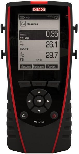
6 1. Presentation 1.1 Instrument description Battery level Measurement menu Configuration menu Date and time Dataset menu Information menu Home screen Function keys Navigation arrows OK button ESC button On/Off button 1.2 Key description Left key: allows to navigate from left to right Right key: allows to navigate from right to left Up key: increments a value or a level Down key: decrements a value or a level OK key: validates an action Esc key: cancels the action or backs to previous step 6 Presentation


7 1.3 Remove battery Turn off the instrument. Turn it over. Press the red button while sliding down the battery. Presentation 7

. In addition, printing is fast.")

. 2.")
8 2. Connections of the VT210 Module Location to remove the module Probe handle C2 mini-din connection C1 minidin connection Connexion USB + alimentation secteur Témoin lumineux de batterie en charge Battery 2.1 Main features Screen 120x160 pixels graphic display and backlight. Display of 6 measurements, 3 simultaneously. Size 50x67 mm. Printer (available as option) The paper of the instrument is a thermal paper with a 10-year guarantee. It has an easy replacement system of the paper (Easyload). In addition, printing is fast. Battery Rechargeable Li-ion battery inside the instrument, 16 h battery-life with a pressure module or 14 h a hotwire probe. The instrument is supplied with a 5 V, 1 A power adapter to load the internal battery. The current loading is indicated by a battery symbol on the top left of the screen. The orange led on the bottom of the instrument is also on until the full loading of the battery (the led turns green). 2.2 Connections Interchangeable modules The interchangeable modules have the SMART-2014 system and are automatically recognized once the connection is made on the instrument. Thermocouple module: Allows to measure temperature on Tc1, Tc2, Tc3 and Tc4 channels with wired thermocouples K, J, T or S probes ended with a male miniature connector 8 Connections of the VT210


 C2 mini-din connection C1 mini-din connection Overmolded")


9 Climatic conditions module: Allows to measure hygrometry, ambient temperature and atmospheric pressure. Wire probes with SMART-2014 system Wire probes with SMART 2014 system are automatically recognized when connected to the instrument. Probes are connected on min-din connectors C1 and / or C2 (excepted thermocouple probes) C2 mini-din connection C1 mini-din connection Overmolded mini-din connector with foolproofing system. Cable length lg. 450 mm, extension 2.4 m. Wireless probe / instrument communication Wireless communication between probe and instrument with automatic recognition after power-up. Wireless probes shall be located near the instrument for initial recognition. Connection between VT210 and wireless probes must be established. Connections of the VT210 9

10 3. Information Information menu allows to view information about the instrument, probes and module connected to the Wireless probe, Mini-DIN 1, Mini-DIN 2 or Module connections. To enter in this menu from home screen, select the Information menu with the arrow keys then press OK. Available information for probes and module is: Type of probes and module Date of the last calibration or adjustment Serial number Firmware version Measuring range Available information for the instrument is: Type of instrument Serial number Firmware version The function key Measurement allows to access directly to the Measurement menu. 10 Information


11 4. Set the instrument The instrument is on. With the arrow keys, go to Configuration menu. Press OK. 4.1 Set language Configuration screen is displayed. Select Language with the arrow keys then press OK. Available languages are displayed. Press Up and Down arrows to select the required language: FRA, ENG... Press OK. 4.2 Set date and time Configuration screen is displayed. Select Date/time with the arrow keys then press OK. The screen of configuration for date and time is displayed. Go to the Date format with arrow keys then press OK. Select: DD/MM/YYYY, MM/DD/YYYY or YYYY/MM/DD then press OK. Go to the day then press OK. With Up and Down keys, set the first digit of the day then go to the following one with right arrow. Press OK to validate. Perform the same procedure to set the month and year. Go the Time format with arrow keys then press OK. Select the time format: 12H or 4H then press OK. If 12H is selected, it is possible to choose between AM for ante meridiem or PM for post meridiem. Press OK, select AM or PM then press OK to validate. Go the time then press OK. With Up and Down keys set the first digit of the day then go to the following one with right arrow. Press OK to validate. Perform the same procedure to set minutes and seconds. Press function key Validate to leave the screen and to save modifications or press Esc to cancel. 4.3 Activate or deactivate the beep key Configuration screen is displayed. Select Key beep with arrow keys. Press OK to activate or deactivate the beep key. The box is ticked if the beep is activated and unticked when the beep is deactivated. 4.4 Set auto-off The auto-off function turns off the instrument after a moment of unused. It is possible to set the auto-off of the instrument at 15 / 30 / 45 / 60 / 75 / 90 / 105 or 120 minutes or to deactivate it. Configuration screen is displayed. Select Auto-off with arrow keys then press OK. Select the required duration or OFF to deactivate it with Up and Down keys. Press OK to validate. Set the instrument 11


12 4.5 Set backlight Configuration screen is displayed. Select Backlight with arrow keys then press OK. Select the backlight level between 1 and 9 or Auto with Up and Down keys. Press OK to validate. 4.6 Set security This part allows to activate or deactivate a security code. This code will be asked when starting the instrument. Configuration screen is displayed. Select Security with arrow keys. Press OK to activate or deactivated the security. If the security is activated, please create a security code. 4.7 Set code If the security is activated, the selected code will be asked when starting the instrument. Configuration screen is displayed and the security is activated. Go to Code then press OK. With arrow keys, set each digit then press OK when the last digit is set. Modifications are validated, the instrument backs to Configuration screen. 4.8 Set printing Configuration screen is displayed. Select Printing with arrow keys then press OK. Go to Format then press OK. Select the ticket format: long or short then press OK. Long ticket format: prints the measurement results + header (operator name, date and time of the intervention, type of instrument and its serial number) Short ticket format: prints only the measurement results and the serial number of the instrument Go to Logo then press OK to activate or deactivate it. The box is ticked when the logo is activated and unticked when the logo is deactivated. Go to Operator to enter an operator name then press OK. Keypad is displayed on the bottom of the screen. Select the letters with arrow keys then press OK. To go from the lower case keypad to the upper case keypad then to the numeric keypad: press the function key: To delete a letter press the function key Delete. Press the function key Validate to validate the name. Go to Header 1 to enter the header name then press OK. Keypad is displayed on the bottom of the screen. Select the letters with arrow keys then press OK. Press the function key Validate to validate the header 1. Perform the same procedure to enter a name for the Header 2, Header 3 and Header 4. Press ESC to back to the Configuration screen and to validate the modifications. 12 Set the instrument


 Airflow direction Protective tube of the sensitive element (1) Bottom of the")
 of the sensitive element (except vane probe).")
13 5. Set the probes 5.1 Use of the wire probes and modules Connect a probe Connect the mini-din cable on the mini-din connection of the probe. Connect the mini-din cable with the probe on the instrument. A beep indicates that the operation has been correctly performed. Flèche face à l'utilisateur Arrow in front of the user Probe connection Instrument connection Go to Measurement menu from the home screen. Press OK Measurement are displayed. 5.2 Special precautions for air velocity probes Sensitive element (velocity) Sensitive element (temperature) Airflow direction Protective tube of the sensitive element (1) Bottom of the telescopic probe landmark Bottom of the standard probe Before any use of the device with an air velocity probe, please lower the protective tube (1) of the sensitive element (except vane probe). Always use the standard air velocity probe with the red point in front of the flow. Always use the telescopic probe with the white point in front of the flow. Set the probes 13


14 5.3 Use of wireless probes Add a wireless probe With arrow keys, go to Information menu then press OK. In Information menu go to Wireless probe then press OK. The probe information is displayed With the function key Meas. It is possible to back to the measurement screen. It is also possible to delete the wireless probe pressing the function key Delete. OR With arrow keys, go to Measurements menu then press OK. The probe information is displayed With the function key Meas. It is possible to back to the measurement screen. It is also possible to delete the wireless probe pressing the function key Delete. 14 Turn on the wireless probe and keep it press until the light blinks On the bottom of the screen press the function key Create. In Measurement menu, press the function key Channels. Pairing is in progress Press the function key Probes. Turn on the wireless probe and keep it press until the light blinks Pairing is in progress With the arrow keys, select Add wireless probe... then press OK. On the bottom of the screen press the function key Create. Set the probes

15 6. Channel configuration The channel configuration allows to modify the displaying of the measured parameters. The instrument is on. With the arrow keys, go to Measurement. Press OK. Press the function key Channels. The different functions of the probe are displayed. It is possible from the Channels menu to add or delete some measurements. Press the function key Delete in order to delete the selected measurement. Press the function key Add to display the selected measurement. Press Add to add a measurement on the screen (the default measurement displayed on the screen are the primary measurements). It is possible from the Channels menu to choose the displaying order of the measurement on the screen. With arrow keys, select the measurement to modify and press OK. Go to the line Channel num. then press OK. Select the channel number and press OK. 6.1 In airflow mode Airflow: In the channels menu: Select with arrow key the sub-menu Airflow then press OK. Select Channel num. and press OK. Select a channel number and press OK. Go to the line Type then press OK. Select the required type: Rect, Circ or K factor and press OK*. If Rect is selected, go to the line Rect then select its dimension: 100x100, 200x200, 300x300, 400x400, 500x500, 600x600, 700x700, 800x800, 900x900 and 1000x1000 mm. Press OK to validate. OR If Circ. is selected, go to the line Diam, then select its dimension : 100, 200, 300, 400, 500, 600, 700, 800, 900 and1000 mm. Go to the line Areas then press OK. It is possible to change units and size. Select Unit with the arrow keys then press OK. Select mm or in and press OK. To modify areas, select with arrow keys Rect. or Circ. and press OK. Select the size to modify in the list and press OK. Set the size with arrow keys between 1 and 2500 mm then press OK. Press ESC to back to the Airflow menu. Go to d/p elem. to select the differential pressure element then press OK. Select the element between Pitot L (coefficient: ), Pitot S (coefficient: 0.84), Debimo (coefficient: ) and Other Go to the line K2 fact. and press OK to select or unselect the K2 factor. K2 factor is a coefficient which is applied to correct the flow rate only for the rectangular or circular surfaces. To select Cone, go to the line Cone then press OK. Select the type of cone: K35, K75, K120 or K150 and press OK. Press Measures to display the measurements. Channel configuration 15
16 6.2 Delta T Delta T is a function which allows to define a temperature difference calculated between two temperature channels of the same type. Connect the thermocouple module then the probes. In the Channels menu: Select with arrow keys the sub-menu Delta T then press OK. Select Channel number and press OK. Select a channel number and press OK. Select the channels in which Delta T will be calculated. Go to Channel A with arrow keys and press OK. Select the channel T1, T2, T3 or T4 and press OK. Go to Channel B with arrow keys and press OK. Select the channel T1, T2, T3 or T4 and press OK. Press the key Measurement. The instrument displays the measurements. 16 Channel configuration


17 7. Start and record datasets The instrument in on. Select with arrows keys Measurement menu. Press OK. Select with arrows keys the measurement in which the dataset will be performed. Press Functions key then select Dataset with arrow keys and press OK. Dataset menu is displayed. Go to line Name with arrow keys and press OK. A keypad is displayed on the bottom of the screen. Select the letters with arrow keys then press OK. To go from the lower case keypad to the upper case keypad then to the numeric keypad: press the function key: To delete a letter press the function key Delete. Press the function Validate to validate the name of the dataset. A dataset is composed of several dated measuring points. You can choose between an automatic dataset or a manual dataset. Go to Type with arrow keys then press OK. Select Manu. for manual or Auto. for automatic. Go to Start then press OK. 7.1 Start and record datasets Manual dataset A manual dataset is composed of measuring points selected by the operator. Manual mode is selected, measurements are displayed. Press OK to validate a measuring point. Press OK as many time as the required number of points. Press the function key Save. The instrument displays the measuring dataset: type of dataset, number of points, date, minimum, maximum, average and standard deviation. The dataset is automatically recorded. Press OK to display the graph of the results. Press the function key Zoom+ to display the detail of the calculated points. Press Esc key to back to the dataset screen. Press the function key Print to print the dataset. Printing mode is displayed. Go to the line Channels info and press OK to print the channels on the printing ticket. Go to the line Details and press OK to print details of the dataset on the printing ticket. Press the function key Validate to print. The instrument backs to the dataset display. Press Esc to back to measurement menu Automatic dataset An automatic dataset is composed of measuring points with interval of time. Automatic mode is selected, measurements are displayed. Press the function key Duration to set the dataset duration. Press OK on the line Duration. Go to Hour with the arrow keys then press OK, set the duration with arrow keys then press OK. Perform the same procedure for the minutes and seconds. Start and record datasets 17
18 Press the function key Validate when the duration is set. Press OK on the line Interval. Go to min with the arrow keys then press OK, set the duration with arrow keys then press OK. Perform the same procedure for the seconds. Press the function key Validate when the interval is set. Press Esc to back to measuring dataset. Press the function key Start to launch the measuring dataset. The countdown starts. It is possible to stop the measuring dataset by pressing the function key Stop. Press Start to restart the dataset. Press Duration to modify the duration. Press Save to save the dataset. The instrument displays the measuring dataset: type of dataset, number of points, date, minimum, maximum, average and standard deviation. The dataset is automatically recorded. Press OK to display the graph of the results. Press the function key Zoom+ to display the detail of the calculated points. Press Esc key to back to the dataset screen. Press the function key Print to print the dataset. Printing mode is displayed. Go to the line Channels info and press OK to print the channels on the printing ticket. Go to the line Details and press OK to print details of the dataset on the printing ticket. Press the function key Validate to print. The instrument backs to the dataset display. Press Esc to back to Measurement menu View the recorded datasets Go to the Dataset menu with the arrow keys from the home screen. The different measuring datasets are displayed. They are listed by date. To delete all the datasets: press the function key Del all. To delete just one dataset: go to the dataset to delete with the arrow keys and press the function key Delete. A confirmation window opens: select YES to confirm the deletion or NO to cancel. 7.2 Launch and save averages The instrument is on. Go to Measurement with the arrow keys. Press OK. Press the function key Functions then select Averages then press OK. Average menu is displayed Point/Point average This function allows to calculate the average value of various points that you can select. Go to Point/Point line in the Averages menu and press OK. Press OK to add measuring points. The instrument displays the type of dataset, number of points, date, minimum, maximum, average and standard deviation. Press the function key Details to get details for each point. Press the function key Save to save the Point/Point average. A keypad is displayed on the bottom of the screen. Select the letters with arrow keys then press OK. To go from the lower case keypad to the upper case keypad then to the numeric keypad: press the function key: 18 Start and record datasets


19 To delete a letter press the function key Delete. Press the function key Validate to validate the name. The recap of the Point/Point average is displayed. Press OK to display the graph. Press the function key Zoom+ to display the detail of the calculated points. Press Esc key to back to the dataset screen. Press the function key Print to print the dataset. Printing mode is displayed. Go to the line Channels info and press OK to print the channels on the printing ticket. Go to the line Details and press OK to print details of the dataset on the printing ticket. Press the function key Validate to print. The instrument backs to the Point/point average display. Press Esc to back to Measurement menu Automatic average This function allows to calculate an average value that the device measured in an interval chosen time. Go to Automatic line in the Averages menu and press OK. Press the function key Start to start the measurement. Duration is displayed. Press the function key Stop to stop the measurements. Measurements, average, minimum and maximum values, standard deviation and duration are displayed. Press the function key Start to launch a new automatic average. Press the function key Save to save the results. A keypad is displayed on the bottom of the screen. Select the letters with arrow keys then press OK. To go from the lower case keypad to the upper case keypad then to the numeric keypad: press the function key: To delete a letter press the function key Delete. Press the function key Validate to validate the name. The recap of the automatic average is displayed.. Press OK to display the graph. Press the function key Zoom+ to display the detail of the calculated points. Press Esc key to back to the dataset screen. Press the function key Print to print the dataset. Printing mode is displayed. Go to the line Channels info and press OK to print the channels on the printing ticket. Go to the line Details and press OK to print details of the dataset on the printing ticket. Press the function key Validate to print. The instrument backs to the automatic average display. Press Esc to back to Measurement menu Automatic Point/Point average This function allows to calculate the average value of various points, calculated themselves on a duration beforehand defined. Go to Auto Pt/Pt line in the Averages menu and press OK. A duration is displayed on the bottom right of the screen. Press the function key Duration to modify the duration if necessary. Go to min with the arrow keys then press OK, set the duration with arrow keys then press OK. Perform the same procedure for the seconds. Press the function key Validate when the interval is set. Start and record datasets 19

20 Press OK to start the measurement. A the end of the measuring dataset, measurements, average, minimum and maximum values, standard deviation and duration are displayed. Press OK to add a new measuring point to the calculation. The countdown starts. Press the function key Details to get details of the results. Press the function key Save to save the results of the automatic average. A keypad is displayed on the bottom of the screen. Select the letters with arrow keys then press OK. To go from the lower case keypad to the upper case keypad then to the numeric keypad: press the function key: To delete a letter press the function key Delete. Press the function key Validate to validate the name. The recap of the dataset is displayed. Press OK to display the graph. Press the function key Zoom+ to display the detail of the calculated points. Press Esc key to back to the dataset screen. Press the function key Print to print the dataset. Printing mode is displayed. Go to the line Channels info and press OK to print the channels on the printing ticket. Go to the line Details and press OK to print details of the dataset on the printing ticket. Press the function key Validate to print. The instrument backs to the automatic point/point average display. Press Esc to back to Measurement menu. 7.3 Hold-Min./Max. Go to Measurement menu with the arrow keys and press OK. Measurements are displayed. Press OK. Measurements are frozen on the screen and the minimum and maximum values are displayed. 20 Start and record datasets
21 8. Setting of measurement parameters The instrument is on. Go to Measurement menu with the arrow keys and press OK. Select the measurement to set with the arrow keys. Press the function key Params. The different parameters are displayed. For all probes and modules, it is possible to modify the channel number. Select Channels with the arrow keys and press OK. Select Channel num. and press OK. Select a channel number for the parameter, and press OK. This number defines the order display of the parameters. 8.1 Thermocouple module Unit Go to the line Temperature and press OK. Select the required unit: C or F Press OK to validate the unit selection Type Go to the line Type Tc and press OK.. Select the type of thermocouple: K, T, J and S Press OK to validate Alarm Go to the line Temp.alarm and press OK. Select High alarm and/or Low alarm by pressing OK. It is possible to set the high and low thresholds. Go to the line High threshold and press OK. Set the threshold with the arrow keys between and C then press OK. Go to the line Low threshold and press OK. Set the threshold with the arrow keys between and C then press OK. 8.2 Climatic conditions module Unit Temperature: Go to the line Temperature and press OK. Select the required unit: C or F Press OK to validate the unit selection. Setting of measurement parameters 21
22 8.2.2 Alarm Temperature: Go to the line Temp.alarm and press OK. Select High alarm and/or Low alarm by pressing OK. It is possible to set the high and low thresholds. Go to the line High threshold and press OK. Set the threshold with the arrow keys between and C then press OK. Go to the line Low threshold and press OK. Set the threshold with the arrow keys between and C then press OK. 8.3 Vane probe and hotwire probe Unit Air velocity: Go to the line Air velocity and press OK. Select with the arrow keys the required unit: m/s, fpm, km/h or mph. Press OK to validate the unit selection. Temperature: Go to the line Temperature and press OK. Select the required unit: C or F Press OK to validate the unit selection. Airflow: Go to the line Airflow and press OK. Select with the arrow keys the required unit: m 3/h, L/s, cfm or m3/s Press OK to validate the unit selection Integration Airflow and air velocity Go the line Integration and press OK. Select the integration coefficient between 0 and 9 with the arro keys. Press OK to validate Alarm Temperature: Go to the line Temp.alarm and press OK. Select High alarm and/or Low alarm by pressing OK. It is possible to set the high and low thresholds. Go to the line High threshold and press OK. Set the threshold with the arrow keys between and C then press OK. Go to the line Low threshold and press OK. Set the threshold with the arrow keys between and C then press OK Normative value Airflow Go to the line Normo Values and press OK. Select None, DIN1343 or ISO2533 and press OK. For a hotwire probe, it is possible to modify the atmospheric pressure. 22 Setting of measurement parameters
23 8.3.5 Atmospheric pressure Go to the line Atmo. Press. and press OK. Select the atmospheric pressure with the arrow keys between 800 and 1200 hpa. Press OK to validate. 8.4 Hygrometry probes Unit Temperature: Go to the line Temperature and press OK. Select the required unit: C or F Press OK to validate the unit selection Alarm Temperature: Go to the line Temp. alarm and press OK. Select High alarm and/or Low alarm by pressing OK. It is possible to set the high and low thresholds. Go to the line High threshold and press OK. Set the threshold with the arrow keys between and C then press OK. Go to the line Low threshold and press OK. Set the threshold with the arrow keys between and C then press OK Atmospheric pressure Go to the line Atmo. Press. and press OK. Select the atmospheric pressure with the arrow keys between 800 and 1200 hpa. Press OK to validate. 8.5 Tachometry Unit Go to the line Tachometry and press OK. Select the required unit: tr/min or RPM. Press OK to validate the unit selection Type Go to the line Tacho type and press OK. Select the required type: Optic or Contact Press OK to validate the type. 8.6 Multifunction probe Unit Air velocity: Go to the line Air velocity and press OK. Select with the arrow keys the required unit: m/s, fpm, km/h or mph. Press OK to validate the unit selection. Temperature: Go to the line Temperature and press OK. Select the required unit: C or F Press OK to validate the unit selection. Setting of measurement parameters 23
24 Airflow: Go to the line Airflow and press OK. Select with the arrow keys the required unit: m 3/h, L/s, cfm or m3/s Press OK to validate the unit selection Atmospheric pressure Airflow and air velocity Go to the line Atmo. Press. and press OK. Select the atmospheric pressure with the arrow keys between 800 and 1200 hpa. Press OK to validate. Temperature: Go to the line Temp. alarm and press OK. Select High alarm and/or Low alarm by pressing OK. It is possible to set the high and low thresholds. Go to the line High threshold and press OK. Set the threshold with the arrow keys between and C then press OK. Go to the line Low threshold and press OK. Set the threshold with the arrow keys between and C then press OK Integration Airflow and air velocity Go the line Integration and press OK. Select the integration coefficient between 0 and 9 with the arro keys. Press OK to validate Normative values Airflow Go to the line Norm Values and press OK. Select None, DIN1343 or ISO2533 and press OK. 24 Setting of measurement parameters
25
26
27
28 Once returned to KIMO, required waste collection will be assured in the respect of the environment in accordance to guidelines relating to WEEE. NTang VT210 17/06/16 RCS (24) Périgueux Non-contractual document We reserve the right to modify the characteristics of our products without prior notice.
VT 210 Thermo-Hygrometer-Anemometer
 VT 210 Thermo-Hygrometer-Anemometer Table of contents 1. Presentation...6 1.1. Instrument description...6 1.2. Key description...6 1.3. Remove battery...7 2. Connections of the VT210...8 2.1. Main features...8
MP 210. Thermo-Anemo-Manometer
 MP 210 Thermo-Anemo-Manometer Table of contents 1. Presentation...5 1.1 Instrument description...5 1.2 Keys description...5 1.3 Remove battery...6 2. Connections of the MP210...7 2.1 Main features...7
1. Presentation. 1.1 Instrument description. 1.2 Keys description
 TM 210 Thermometer Table of contents 1.Presentation...5 1.1. Instrument description...5 1.2. Keys description...5 1.3. Remove battery...6 2.Connections of the TM210...7 2.1. Main features...7 2.2. Connections...7
Multifunction instrument AMI 310
 Multifunction instrument AMI 310 Table of contents 1 Presentation...6 1.1 Instrument description...6 1.2 Remove battery...7 1.3 Insert SD card...7 2 Connections of the AMI310...8 2.1 Main features...8
Supplied with. Calibration certificate. Anemometer VT 200
 Supplied with Calibration certificate Anemometer VT 200 Table of contents 3 I Technical specifications...4 Technical features......4 Specifications......4 II Introduction......5 Description......5 Connections......6
actoolsupply.com MP 200 Manometer Calibration certificate Supplied with actoolsupply.com
 Supplied with Calibration certificate MP 200 Manometer Kimo MP 200 P Thermo Anemometer Manometer Kimo MP 200 M Thermo Anemometer Manometer Kimo MP 200 G Thermo Anemometer Manometer Kimo MP 200 H Thermo
Supplied with. Calibration certificate. TM 200 Thermometer
 Supplied with Calibration certificate TM 200 Thermometer Table of contents 3 I Technical specifications...4 Technical features...4 Specifications...4 II Introduction...5 Description...5 Connections...6
Supplied with. Calibration certificate. TM 200 Thermometer
 Supplied with Calibration certificate TM 200 Thermometer Table of contents 3 I Technical specifications...4 Technical features...4 Specifications...4 II Introduction...5 Description...5 Connections...6
AQ 200 AQ 200 Air Quality
 AQ 200 AQ 200 Air Quality Table of contents 3 I Technical specifications...4 Technical features...4 Specifications...4 II Introduction...5 Description...5 Connections...6 III Browsing...7 IV Menus...8
Supplied with. Calibration certificate. HD 200 Hygrometer
 Supplied with Calibration certificate HD 200 Hygrometer Table of contents 3 I Technical specifications...4 Technical features......4 Specifications......4 II Introduction......5 Description......5 Connections......6
SMART MULTI-FUNCTIONS DEVICES VT 300, 300 PRO and 300 ST
 R Air velocity Pressure Humidity Air flow Temperature CONSTRUCTEUR DIRECTIONS FOR USE SMART MULTI-FUNCTIONS DEVICES VT 00, 00 PRO and 00 ST CLASS 00 New New VT 00 SUMMARY TECHNICAL SPECIFICATIONS... 1-2
Multifunction AMI 300
 Supplied with Calibration certificate Multifunction AMI 300 P a Table of contents 3 I Technical specifications...4 Technical features...4 Specifications...4 II Introduction...6 Description...6 Connections...7
AMI 300 and 300 STD SMART MULTI-FUNCTIONS DEVICES. Pressure sensor from 0 to 1000 mm H O DIRECTIONS FOR USE
 CONSTRUCTEUR R Air velocity Pressure Humidity Air flow Temperature DIRECTIONS FOR USE SMART MULTI-FUNCTIONS DEVICES AMI 00 and 00 STD CLASS 00 New New Pressure sensor from 0 to 1000 mm H O 2 AMI 00 SUMMARY
LCC-S Configuration software for transmitters
 LCC-S Configuration software for transmitters Table of contents 1. Introduction...5 2. Software installation...5 2.1. Minimum system requirement...5 2.2. Installing the software...5 3. Start with the
General Catalogue. Export Pressure Temperature Humidity Air velocity Airflow Air quality Sound level
 General Catalogue Export 2009 Pressure Air velocity Airflow Air quality Sound level Pressure Air Velocity Airflow Tachometry Air Quality F C Wireless probes New Special air quality CO CO ² Portable New
KISTOCK DATALOGGER KT 220 / KH 220 / KTT 220
 KISTOCK DATALOGGER KT 220 / KH 220 / KTT 220 / Humidity / Light / Current Voltage / Impulsion / Water pressure KEY POINTS Available with or without display Software for configuration and data visualisation
Model 6812 VOLUME FLOW ANEMOMETER. User Manual. Kanomax USA, Inc. 219 Route 206 PO Box 372. Andover, NJ USA. (800) Fax: (973)
 Fax: (973)") Kanomax USA, Inc. 219 Route 206 PO Box 372 Andover, New Jersey 07821 USA (800) 247-8887 Fax: (973) 786-7586 Model 6812 VOLUME FLOW ANEMOMETER User Manual www.kanomax-usa.com Copyright 2008, Kanomax USA,
Kanomax USA, Inc. 219 Route 206 PO Box 372 Andover, New Jersey 07821 USA (800) 247-8887 Fax: (973) 786-7586 Model 6812 VOLUME FLOW ANEMOMETER User Manual www.kanomax-usa.com Copyright 2008, Kanomax USA,
Model 6812 VOLUME FLOW ANEMOMETER. User Manual. 219 Route 206 Phone: PO Box 372 Fax: (973)
") Model 6812 VOLUME FLOW ANEMOMETER User Manual Copyright 2008, Kanomax USA, Inc. Page 1 of 29 INTRODUCTION Congratulations on your purchase of a 6812 Digital Anemometer with Volume Calculation! You now
Model 6812 VOLUME FLOW ANEMOMETER User Manual Copyright 2008, Kanomax USA, Inc. Page 1 of 29 INTRODUCTION Congratulations on your purchase of a 6812 Digital Anemometer with Volume Calculation! You now
Before starting installation process, make sure the USB cable is unplugged.
 Table of contents 1 Introduction...4 2 Software installation...4 2.1 Minimum configuration required...4 2.2 Software installation on Windows 7 / Vista / 8...4 2.3 Software installation on Windows XP...4
Digital Air Velocity Meter DC580. The Value Leader TM
 Digital Air Velocity Meter DC580 The Value Leader TM www.testproductsintl.com Contents Introduction... Page 1 General Overview & Guidelines... Page 1 Features and Guidlines... Page 2 LCD Overview... Page
KISTOCK DATALOGGER KT 320 / KTT 320
 KISTOCK DATALOGGER KT 30 / KTT 30 / Humidity / Voltage/ Current / Impulsion KEY POINTS Software for configuration and data visualisation freely downloadable Software for configuration and data processing
User Manual. Heavy Duty Hot Wire CFM Thermo-Anemometer. Model
 User Manual Heavy Duty Hot Wire CFM Thermo-Anemometer Model 407119 Introduction Congratulations on your purchase of the Extech 407119 Thermo-Anemometer. The 407119 measures air velocity, air volume, and
Class 220 KISTOCK. KT 220, KH 220 and KTT 220
 Class 220 KISTOCK KT 220, KH 220 and KTT 220 Table of contents 1 Safety instructions...4 1.1 Precautions for use...4 1.2 Symbols used...4 2 Presentation of the device...5 2.1 Use...5 2.2 Applications...5
VAC analysis measuring instrument
 99 Washington Street Melrose, MA 02176 Phone 781-665-1400 Toll Free 1-800-517-8431 Visit us at www.testequipmentdepot.com VAC analysis measuring instrument testo 480 Cutting-edge technology for professionals
User's Guide. Vane Thermo-Anemometer Datalogger. Model Introduction
 User's Guide Vane Thermo-Anemometer Datalogger Model 451126 Introduction Congratulations on your purchase of Extech's Thermo-Anemometer Datalogger. This Vane-type Anemometer can indicate Air Velocity in
Model 6813 THERMO-ANEMOMETER. User Manual. Kanomax USA, Inc. 219 Route 206 PO Box 372. Andover, NJ USA. (800) Fax: (973)
 Fax: (973)") Kanomax USA, Inc. 219 Route 206 PO Box 372 Andover, New Jersey 07821 USA (800) 247-8887 Fax: (973) 786-7586 Model 6813 THERMO-ANEMOMETER User Manual www.kanomax-usa.com Copyright 2008, Kanomax USA, Inc
Kanomax USA, Inc. 219 Route 206 PO Box 372 Andover, New Jersey 07821 USA (800) 247-8887 Fax: (973) 786-7586 Model 6813 THERMO-ANEMOMETER User Manual www.kanomax-usa.com Copyright 2008, Kanomax USA, Inc
Large Vane CFM/CMM Thermo-Anemometer
 User Manual Large Vane CFM/CMM Thermo-Anemometer Model AN300 Additional User Manual Translations available at www.extech.com Introduction Congratulations on your purchase of the Extech AN300 Vane Airflow
User's Manual. VA893 Thermo Anemometer
 User's Manual VA893 Thermo Anemometer Introduction The VA893 Thermo Anemometer instrument measures Air Velocity, Air Flow (volume) and Temperature. The large, easy-to-read backlit LCD includes primary
Input for universal probe* Inputs for thermocouple probes
 Device reference Display Internal sensor External sensor Number Type Number Type Parameters Number of record points KT 220 - O KT 220 - N KH 220 - O KH 220 - N Yes No Yes No 1 Temperature 3 Temperature,
Heavy Duty Pitot Tube Anemometer and Differential Pressure Manometer
 User Manual Heavy Duty Pitot Tube Anemometer and Differential Pressure Manometer Model HD350 Additional User Manual Translations available at www.extech.com Introduction Congratulations on your purchase
JSP Industrial Controls
 JSP, s.r.o., Raisova 547, 506 01 Jičín, Czech Republic Phone: +420 493 760 811, Fax: +420 493 760 820, e-mail: jsp@jsp.cz JSP Industrial Controls www.jsp.cz Table of contents ANALYSER 1. Introduction...7
HD31. Multifunction Data Logger ENGLISH
 REV. 1.2 28/11/2016 HD31 Multifunction Data Logger ENGLISH The quality level of our instruments is the result of the constant development of the product. This may produce some differences between the information
CFM/CMM Hot-Wire Thermoanemometer
 User Manual CFM/CMM Hot-Wire Thermoanemometer with NIST-Traceable Calibration Model 20250-16 Max Min Flow Temp THE STANDARD IN PRECISION MEASUREMENT 2 Introduction The Digi-Sense CFM/CMM Hot-Wire Thermoanemometer
Datalogging Hot Wire CFM Anemometer
 Datalogging Hot Wire CFM Anemometer 840002 Instruction Manual SPER SCIENTIFIC LTD. TABLE OF CONTENTS 1. INTRODUCTION... 3 2. PANEL DESCRIPTION... 4-5 3. MEASURING PROCEDURE... 5 3-A Air Velocity and Ambient
DATA LOGGERS Reliable solutions for monitoring your processes
 www.sauermann.us DATA LOGGERS Reliable solutions for monitoring your processes Sauermann Data Loggers Innovation, Versatility, & Value Sauermann offers a comprehensive range of data loggers that cover
Model ST-618. Instruction Manual. Digital Thermo-Anemometer. Digital Measurement Metrology, Inc PRECISION IS OUR VISION
 Model ST-618 Digital Thermo-Anemometer Instruction Manual Table of Contents Features... 2 Specifications... 3 Instrument Description... 4 Operating Instructions...4-5 Measuring Wind Velocity...4 Measuring
Large Vane CFM/CMM Anemometer / Psychrometer
 99 Washington Street Melrose, MA 02176 Phone 781-665-1400 Toll Free 1-800-517-8431 Visit us at www.testequipmentdepot.com USER GUIDE Large Vane CFM/CMM Anemometer / Psychrometer Model AN310 Introduction
Table of contents. Minimum required configuration...3 Software installation...3 Launching application...8 Software Un-installation...
 Table of contents I. Installation procedure...3 A B C D Minimum required configuration...3 Software installation...3 Launching application...8 Software Un-installation...8 II. General overview...9 A Instrument
Model 6815 HYGRO-THERMOMETER ANEMOMETER. User Manual. Kanomax USA, Inc. 219 Route 206 PO Box 372. Andover, NJ USA
 Kanomax USA, Inc. 219 Route 206 PO Box 372 Andover, New Jersey 07821 USA (800) 247-8887 Fax: (973) 786-7586 Model 6815 HYGRO-THERMOMETER ANEMOMETER User Manual www.kanomax-usa.com Copyright 2008, Kanomax
MANUAL SPEED SENSOR MSPEED EX
 MANUAL SPEED SENSOR MSPEED EX 1. INTRODUCTION... 2 2. DESCRIPTION... 2 3. CONNECTING MSPEED... 2 3.1 CONNECTING MSPEED TO THE JETI BOX... 2 3.2 CONNECTING MSPEED TO THE DUPLEX RECEIVER... 3 3.3 CONNECTING
GA-12. madur Polska sp. z o.o.
 www.madur.com is madur s smallest gas analyser - hand-held, equipped with up to 3 EC cells. Small dimensions and light weight makes it very convenient for technicians that use analyser on a daily basis.
Model R3001. Instruction Manual. Anemometer/Manometer. reedinstruments. www. com
 Model R3001 Anemometer/Manometer Instruction Manual reedinstruments com Table of Contents Features... 3 Specifications...3-4 Instrument Description...5-6 Operating Instructions...7-10 Measuring Pressure...
Operating Instructions
 Operating Instructions Index Page 1. Design 3 2. Initialisation 2.1. Power supply 4 2.2. Accumulator charging 4 2.3. Clock set 4 3. Numerical indication 3.1. Zeroing pressure sensors 6 3.2. Freezing measurement
350 SMART MANOMETER OPERATING INSTRUCTIONS
 99 Washington Street Melrose, MA 02176 Phone 781-665-1400 Toll Free 1-800-517-8431 Visit us at www.testequipmentdepot.com 350 SMART MANOMETER OPERATING INSTRUCTIONS Meriam Instrument s 350 Smart Manometer
Thermo Scientific Orion Star A329 Portable ph/ise/conductivity/rdo/do Meter. Instruction Sheet
 English ph / ISE / COND / RDO / DO Thermo Scientific Orion Star A329 Portable ph/ise/conductivity/rdo/do Meter Instruction Sheet Preparation Power Source 1. Power adapter (sold separately) a. Select the
AVM-8880 USB Logging Anemometer
 AVM-8880 USB Logging Anemometer Introduction This digital USB logging Anemometer is a precision instrument. It measures airflow levels and has the facilities to record and store measured valves when plugged
SL 200 instrument can process the energy intensity emitted by the solar radiation in a precise place of the earth.
 Solarimeter SL 200 Table of contents 1 Introduction...4 2 General information...4 2.1 Measured units...4 2.2 Use...4 3 Operating principle...5 3.1 Keyboard presentation...5 3.2 Instrument offers 3 groups
AEROTRAK HANDHELD AIRBORNE PARTICLE COUNTER MODEL 9306 QUICK START GUIDE
 AEROTRAK HANDHELD AIRBORNE PARTICLE COUNTER MODEL 9306 QUICK START GUIDE Thank you for purchasing a TSI AeroTrak Model 9306 Handheld Airborne Particle Counter. This guide will help you quickly begin using
AEROTRAK PORTABLE AIRBORNE PARTICLE COUNTER MODEL 9310/9350/9510/9550/9500 QUICK START GUIDE
 AEROTRAK PORTABLE AIRBORNE PARTICLE COUNTER MODEL 9310/9350/9510/9550/9500 QUICK START GUIDE Thank you for purchasing a TSI AeroTrak Portable Airborne Particle Counter (particle counter). This guide will
SUMMARY. Minimum required configuration... Software installation... User logo customisation... Software Un-installation... Launching application...
 1 SUMMARY I. Installation procedure...3 A B C D E Minimum required configuration... Software installation... User logo customisation... Software Un-installation... Launching application... 3 3 3 3 3 II.
Thermo Scientific Orion Star A326 Portable ph/rdo/do Meter. Instruction Sheet
 English ph / RDO / DO Thermo Scientific Orion Star A326 Portable ph/rdo/do Meter Instruction Sheet Preparation Power Source 1. Power adapter (sold separately) a. Select the appropriate wall socket plug
Kistock 2015 Configurator
 Kistock 2015 Configurator Table of contents 1 Software presentation... 4 2 Means for software use... 4 3 Recommendations... 4 4 Instructions... 4 4.1 Classes 50, 70 and 120 Kistock... 4 4.2 Classes 150,
MicroTrans EQ Signal Processor. Operation & Maintenance Manual
 MicroTrans EQ Signal Processor Operation & Maintenance Manual Engineered for accuracy, applicability, durability and simplicity in HVAC air systems and industrial process control loops TABLE OF CONTENTS
[ Air Velocity Measurement Techniques from Alnor
 8 Alnor EBT720 and EBT721 range DIFFERENTIAL PRESSURE ±15 in. H 2 O, (3735 Pa) 150 in. H 2 O maximum safe operating pressure ABSOLUTE PRESSURE 15 40 in. Hg (356 to 1016 Hg) 25 8,000 ft/min (0.125 40 m/s)
Heavy Duty Mini Vane CFM Thermo Anemometer
 User's Manual Heavy Duty Mini Vane CFM Thermo Anemometer Model 407117 WARRANTY EXTECH INSTRUMENTS CORPORATION warrants this instrument to be free of defects in parts and workmanship for three years from
Digital thermometer-hygrometer with external temperature probe Instruction manual
 COMMETER C3631 Digital thermometer-hygrometer with external temperature probe Instruction manual Manual for use of thermometer-hygrometer COMMETER C3631 with external temperature probe Instrument is designed
PosiTector DPM. Dew Point Meter. INSTRUCTION MANUAL v Simple. Durable. Accurate.
 PosiTector DPM Dew Point Meter INSTRUCTION MANUAL v. 2.0 Simple. Durable. Accurate. Introduction The Dew Point Meter is a hand-held, electronic instrument that measures, calculates and records climatic
Manual Anemometer PCE-423
 PCE Americas Inc. 711 Commerce Way Suite 8 Jupiter FL-33458 USA From outside US: +1 Tel: (561) 320-9162 Fax: (561) 320-9176 info@pce-americas.com PCE Instruments UK Ltd. Units 12/13 Southpoint Business
LIMITATION OF WARRANTY AND LIABILITY (effective June 2011)
") ENERGY AND COMFORT Ventilation Testing VELOCICALC Air Velocity Meter Model 9565 Series Operation and Service Manual Copyright TSI Incorporated / 2011-2012 / All rights reserved. LIMITATION OF WARRANTY
ENERGY AND COMFORT Ventilation Testing VELOCICALC Air Velocity Meter Model 9565 Series Operation and Service Manual Copyright TSI Incorporated / 2011-2012 / All rights reserved. LIMITATION OF WARRANTY
Heavy Duty Hot Wire CFM Thermo-Anemometer
 User's Guide 99 Washington Street Melrose, MA 02176 Phone 781-665-1400 Toll Free 1-800-517-8431 Visit us at www.testequipmentdepot.com Back to the Extecch 407119 Product Page Heavy Duty Hot Wire CFM Thermo-Anemometer
USER MANUAL Video Particle Counter with built in Camera Model VPC300
 USER MANUAL Video Particle Counter with built in Camera Model VPC300 Additional User Manual Translations available at www.extech.com Introduction Thank you for selecting the Extech Instruments Model VPC300
Anemometer SD Card Datalogger. Instruction Manual
 Anemometer SD Card Datalogger 850023 Instruction Manual 1 Anemometer SD Card Datalogger 850023 Copyright 2010 by Sper Scientific ALL RIGHTS RESERVED Printed in the USA The contents of this manual may not
QUICK START. ATEQ F620 Version 1.0. Reference: MR-28300A-U. (Photo no contractual)
") QUICK START ATEQ F620 Version 1.0 (Photo no contractual) Reference: MR-28300A-U REVISIONS OF THE ATEQ F620 USER MANUAL Due to continuing improvements, the information contained in this user manual, the
QUICK START ATEQ F620 Version 1.0 (Photo no contractual) Reference: MR-28300A-U REVISIONS OF THE ATEQ F620 USER MANUAL Due to continuing improvements, the information contained in this user manual, the
PROFESSIONAL WIRELESS WEATHER STATION. Operation Manual - 1 -
 PROFESSIONAL WIRELESS WEATHER STATION Operation Manual - 1 - OVERVIEW Outdoor sensor: 1. Wind Vane 2. Wind Speed Sensor 3. Solar panel 4. Battery compartment 5. LED Indicator: light on for 4 seconds during
HAND-HELD GAS ANALYSER
 HAND-HELD GAS ANALYSER Manual Version: 1.0 11/2010 Index 1. Introduction...3 2. Construction of the GA-12 gas analyser...4 2.1. Electric connections...4 2.2. Gas channel...5 2.3. Supply...5 3. Maintenance
VELOCICALC AIR VELOCITY METER MODEL 9565 SERIES
 VELOCICALC AIR VELOCITY METER MODEL 9565 SERIES OPERATION AND SERVICE MANUAL P/N 6004851, REVISION D OCTOBER 2014 Copyright TSI Incorporated / 2011-2014 / All rights reserved. Address TSI Incorporated
Datalogging IAQ Meter Instruction Manual
 Datalogging IAQ Meter 800050 Instruction Manual Datalogging IAQ Meter 800050 Copyright 2014 by Sper Scientific ALL RIGHTS RESERVED Printed in the USA The contents of this manual may not be reproduced or
SPECIFICATIONS HAND HELD PARTICLE COUNTER KC Higashimotomachi, Kokubunji, Tokyo , Japan
 SPECIFICATIONS HAND HELD PARTICLE COUNTER KC-52 3-20-41 Higashimotomachi, Kokubunji, Tokyo 185-8533, Japan No. 10017-3E 18-04 Printed in Japan Outline The hand held particle counter KC-52 is designed to
TITAN S8. Portable Data Acquisition Logger. Product User Guide
 TITAN S8 Portable Data Acquisition Logger Product User Guide Table of Contents 2 General Features... 3 Device Overview... 3 External Features... 3 Device Orientation... 4 Device Inputs... 5 Sensor Types
Thermo Scientific Orion Star A324 Portable ph/ise Meter. Instruction Sheet
 English ph / ISE Thermo Scientific Orion Star A324 Portable ph/ise Meter Instruction Sheet Preparation Power Source 1. Power adapter (sold separately) a. Select the appropriate wall socket plug plate.
testo 440 Climate Measuring Instrument Instruction manual
 testo 440 Climate Measuring Instrument Instruction manual Contents Contents 1 Safety and disposal... 3 1.1 About this document... 3 1.2 Security... 3 1.3 Warning notices... 4 1.4 Disposal... 5 2 Description
MobilControl MC 4000 OWNER S MANUAL
 MobilControl MC 4000 Hand Held Service instrument with data logger for pressure, min / max & differential pressure, temperature, flow / rpm and hydraulic horsepower OWNER S MANUAL 20 7 TERMINALS 7.1 Plugs
Digital thermo-hygro-barometer with external probe Manual for use
 COMMETER D4141 Digital thermo-hygro-barometer with external probe Manual for use Instruction manual for use of thermo-hygro-barometer COMMETER D4141 Instrument is designed for measurement and data logging
3 Channel Datalogging Thermometer
 USER MANUAL 3 Channel Datalogging Thermometer Model SD200 Introduction Congratulations on your purchase of the Extech SD200 3-Channel Temperature Datalogger. This meter displays and stores temperature
Thermo-Anemometer Data Logger Model 1227
 Thermo-Anemometer Data Logger Model 1227 Quick Start Guide ENGLISH www.aemc.com Statement of Compliance Chauvin Arnoux, Inc. d.b.a. AEMC Instruments certifies that this instrument has been calibrated using
OPTERATING MANUAL. TT Series Micromanometer 550 High Resolution
 OPTERATING MANUAL TT Series Micromanometer 550 High Resolution Page 00 CONTENTS Limitations of Use 01 Keypad Controls 02 Mode of Operation 03 Display 04 Pressure Connections 05 Volume Flow Rates 05 Velocity
Ventilation Testing. Air Velocity Meter. AIRFLOW Instruments Model TA465. Operation and Service Manual
 Ventilation Testing Air Velocity Meter AIRFLOW Instruments Model TA465 Operation and Service Manual Copyright TSI Incorporated / 2011 / All rights reserved. Address TSI Incorporated / 500 Cardigan Road
 PCE Instruments UK Ltd Units 12/13 Southpoint Business Park Ensign Way, Southhampton Hampshire United Kingdom, SO31 4RF Phone +44(0) 2380 98703 0 Fax +44(0) 2380 98703 9 info@industrial-needs.com Thermometer
ET-961 Hot Wire Thermo-Anemometer User Manual
 ET-961 Hot Wire Thermo-Anemometer User Manual Please read this user manual thoroughly before using this meter and store it for future reference. Contents 1. General Description 2 2. Features...2 3. Specifications..3
DPL4000 Portable Low Range Dew Point Analyzer
 OPERATIONS MANUAL DPL4000 Portable Low Range Dew Point Analyzer 7205 Edington Drive / Cincinnati, OH 45249 / Tel (513) 772-0060 / Fax (513) 772-9466 Page #1 of 16 M4581 DPL4000 Product Description: This
ANEMOMETER OPERATION MANUAL. Model : AM-4207SD. SD card real time datalogger + Type K/J thermometer
 SD card real time datalogger + Type K/J thermometer ANEMOMETER Model : AM-4207SD Your purchase of this ANEMOMETER with SD CARD DATALOGGER marks a step forward for you into the field of precision measurement.
Heavy Duty CFM Thermo-Anemometer Model
 User's Guide Heavy Duty CFM Thermo-Anemometer Model 407113 3 Introduction Congratulations on your purchase of the Extech 407113 CFM meter. This handheld meter can display Air Flow (CFM) with Area or Air
Operation Manual. rev Charge then remove battery when stored for more than 1 week. Flow Finder MK2. Powered Flow Hood
 Operation Manual rev-2017-04-20 Flow Finder MK2 Charge then remove battery when stored for more than 1 week Powered Flow Hood 1. Introduction The FlowFinder mk2 is the successor of the well-known FlowFinder
Mini Environmental Quality Meter
 Mini Environmental Quality Meter 850025 7720 E. Redfield Rd. Suite #7, Scottsdale, AZ 85260 Tel: (480) 948-4448 Fax: (480) 967-8736 Web: www.sperscientific.com Mini Environmental Quality Meter 850025 Copyright
2 Product Overview. 5 User Interface. 14 Logging Data. 17 Viewing Data. 19 Managing Data. 24 Device Settings. 26 Specifications.
 TITAN S8 Portable Data Acquisition Logger PRODUCT USER GUIDE To view the full MadgeTech product line, visit our website at madgetech.com. TABLE OF CONTENTS 2 Product Overview 5 User Interface 14 Logging
Hand-held thermometer Model CTH7000
 Calibration technology Hand-held thermometer Model CTH7000 WIKA data sheet CT 55.50 Applications Precision thermometer for very accurate temperature measurements in a range of -200... +962 C Reference
Mini Environmental Quality Meter
 Mini Environmental Quality Meter 850025 Mini Environmental Quality Meter 850025 Copyright 2012 by Sper Scientific ALL RIGHTS RESERVED Printed in the USA The contents of this manual may not be reproduced
PIECAL 322 Automated Thermocouple Calibrator Operating Instructions. Product Description. Practical Instrument Electronics
 PIECAL 322 Automated Thermocouple Calibrator Operating Instructions Product Description Easy to use With the PIECAL 322-1 you can check & calibrate all your thermocouple instruments and measure thermocouple
ARA FTS Flow Calibrator. Operation Manual August 1, 2016
 ARA FTS Flow Calibrator Operation Manual August 1, 2016 TABLE OF CONTENTS SECTION PAGE 1. INTRODUCTION 1 2. GETTING STARTED 1 2.1. Navigation 1 2.2. Charge Battery 1 2.3. Set Date and Time 2 2.4. Plug-In
VELOCICALC Air Velocity Meter Model 9565 Series
 ENERGY AND COMFORT Ventilation Testing VELOCICALC Air Velocity Meter Model 9565 Series Operation and Service Manual Copyright TSI Incorporated / 2011-2012 / All rights reserved. Address TSI Incorporated
Handheld Laser Particle Counter. Model: P311. Operation Manual. Ver: 1.50 AIRY TECHNOLOGY INC
 Handheld Laser Particle Counter Model: P311 Operation Manual Ver: 1.5 AIRY TECHNOLOGY INC 1 Warranty AIRY TECHNOLOGY INC warrants to the original user that this instrument shall be free from defects in
Summary I Minimum system requirements...2
 Logiciel 1 Summary I Minimum system requirements...2 I 1 Minimum configuration required...2 I 2 uninstallation...2 I 3 Launching application...2 II installation...2 III presentation...3 III 1 Home page...3
HD2107.1, HD2107.2, HD2127.1, HD2127.2
 HD2107.1 HD2107.2 HD2127.1 HD2127.2 HD2107.1, HD2107.2, HD2127.1, HD2127.2 TC input: 1 1 2 2 Storage capacity PC interface ---- 76000 samples ---- RS232C RS232C + USB2.0 RS232C 38000 couples of temperatures
99 Washington Street Melrose, MA Fax TestEquipmentDepot.com DPI 820. Dual Input Thermometer. User manual.
 99 Washington Street Melrose, MA 0276 Fax 78-665-0780 TestEquipmentDepot.com DPI 820 Dual Input Thermometer User manual A B 0 0 0a 9a A 2 9 8 2 3 7 6 4 5 B 2 A2 6 5 4 3 22 7 8 2 9 20 Test Equipment Depot
SPECIFICATIONS HAND HELD PARTICLE COUNTER KC Higashimotomachi, Kokubunji, Tokyo , Japan
 SPECIFICATIONS HAND HELD PARTICLE COUNTER KC-51 3-20-41 Higashimotomachi, Kokubunji, Tokyo 185-8533, Japan No. 10015-2E 15-06 Printed in Japan Outline The hand held particle counter KC-51 is designed to
Hand-held thermometer Model CTH7000
 Calibration technology Hand-held thermometer Model CTH7000 WIKA data sheet CT 55.50 for further approvals see page 2 Applications Precision thermometer for very accurate temperature measurements in a range
Thermo Scientific Orion Star A214 Benchtop ph/ise Meter. Instruction Sheet
 English ph / ISE Thermo Scientific Orion Star A214 Benchtop ph/ise Meter Instruction Sheet Preparation Power Source 1. Power adapter (included with meter) a. Select the appropriate wall socket plug plate.
C100 Portable Multifunction
 C100 Portable Multifunction Superior Accuracy as compared to Competitors! Wahl C100 Simultaneous Measurement and Generation Rugged IP54 Construction for On Site Use Quick Connect Terminals Measurement