The Tracker. How the Tracker Works
|
|
|
- Aileen Barber
- 6 years ago
- Views:
Transcription

1 The Tracker How the Tracker Works Hardware Tracker interface circuit board Tracker input circuit Connecting the machine signals to the Tracker Connecting the Tracker to your computer Powering up the Tracker Using the Comtest Program Software Software installation Software removal Where to Store the Files Starting Tracker for the First Time Change Host Directory Change Archive Directory Change COM Port Assignments The Screens Line Status Screen Job Status Screen Last 50 Cycles Screen Summary Screen How To: Update Machine Tags Update Shift Times Update Passwords Update Summary Screen Assignments Enter Downtime Reasons Enter Presets Enter Jobs into the Job Queue Update, Reset, or Close Current Jobs Enter Rejects and Reasons Edit and View Shift Notes Edit the Debouncers Page 1

2 How The Tracker Works The TRACKER unit monitors up to forty eight (48) machines by continuously scanning each optically isolated input for a cyclic electrical signal from your machines at a thousandth of a second. As the machines cycle, the signals will change state from de-energized, to energized, and back again. Upon detection of a state change, the TRACKER unit will transmit a one (1) byte code for each detection via the RS232 serial connection to your personal computer, designated as the host computer. The serial interrupt causes the software to receive the code, time stamp it, and store it in a circular buffer to be processed in a first in, first out (FIFO) manner. When a mold is put into a machine, a job should be entered into the Tracker system. This tells the Tracker the duration of a nominal cycle, the upper and lower limits of that cycle, how much time is allowed to pass without seeing a cycle, and the number of parts you want to produce. The Tracker will now monitor that machine for cycles, displaying counts, cycle times, efficiencies, and updating predictive information such as parts to go, hours to go, material to go, and the job s stop date. When the job is completed, the operator closes the job in the Tracker system and the information is archived. If you know which jobs are to be run on a machine and in which order, you can preload them into the job queue. As a job is closed, the next job in the job queue is automatically loaded for monitoring. Finding all the running parameters for a job can be a hassle. The Tracker can save the job s parameters so you can recall them just by selection the description from a list. Report fields are selectable and are displayed to the screen first. If you like what you see, click the Print button to send the report to any printer. If the host computer is on a network, workstations can be setup to run the Tracker program so they have virtually full access to the Tracker data, including edit and reporting capabilities. Page 2

3 Tracker Interface Circuit Board The TRACKER unit itself is housed in a steel Hoffman box for industrial use. The knockouts located around the box provide easy access for cables and power. There are two holes on the back of the box for mounting convenience. On the inside of the TRACKER unit, you will find a single printed circuit board with one (1) 3-pin connector on the top center just above the microprocessor, one (1) 2-pin connector by the power supply, and forty-eight (48) 2-pin connectors in four columns. Should the need ever arise to remove the board for service, simply unplug all the connections and remove the four (4) corner screws. Page 3
4 Tracker Input Circuit Each input circuit consists of six (6) 1/2W resistors in series connected to two (2) 500mcf leds, one in reverse polarity from the other. The on voltage can be either twelve (12) to thirty (30) volt VDC, or twenty-four (24) to one hundred twenty (120) volt VAC. If an AC voltage is applied, both leds will light. If a DC voltage is applied without regard to polarity, either one of the leds will light. NOTE: The translucent cover over the input circuits was installed to allow you to see the machine signals as they occur. The input circuits are sensitive to external ambient light. Page 4
5 Connecting the Machine Signals to the Tracker The 2-pin connectors arranged in four columns are where each machine terminates on the TRACKER interface circuit board. The machine signal should be cyclic and that you get only ONE off-on-off transition per physical cycle. The on voltage can be either twelve (12) to thirty (30) volt VDC, or twenty-four (24) to one hundred twenty (120) volt VAC. Since each line is optically isolated, you can mix and match the voltages to the TRACKER interface circuit board. Wiring from the machines should be at least 20AWG 2-conductor unshielded twisted pair. Page 5

6 Connecting the Tracker to your Computer The TRACKER unit comes with a 6-foot temporary serial cable for immediate use. The serial connection has been tested out to 1000 feet. The serial cable has a 3-pin plug at one end and a DB25 connector joined at the other end by an RJ-11 connection. NOTE: Please note that when routing the serial cable, avoid close proximity to transformers and fluorescent lighting fixtures, as they tend to disrupt the data signal. The only pinout connections used in the serial cable are pin #1 (black) and pin #7 (yellow) for ground, pin #2 (red) for receive and pin #3 (green) for transmit. Be sure that the AC power to the Tracker is disconnected when working on the serial connection. If the transmit and receive wires touch when the unit is powered up, damage may result to the RS232 interface chip. Insert the 3-pin plug into the 3-pin socket at the top center of the board, the wires facing away from the board, with the green on the left, red in the center, and black & yellow tied together on the right. Hold the RJ-11 connector that plugs into the DB25 connector so the tab is facing away from you, and you can see the gold pins on top. The wires inside the connector should be, from left to right, black, red, green, yellow. Plug the RJ-11 connector into the end of the DB25-connector. The DB25 connector should be plugged into the computer's serial port. This should be either a 25-pin male connection or a 9-pin male connection on the computer. To connect the DB25 connector to a 9-pin serial port, you'll need a 25-to-9 serial adapter that has a 25-pin male connection on one side and a 9-pin female connection on the other side. These can be purchased at Radio Shack or Sears. Serial communication settings are fixed at baud, no parity, 8 data bits, and 1 stop bit. Page 6
7 Powering up the Tracker The 2-pin connector by the power supply is for the 120VAC to power the TRACKER unit. With the serial cable in place, power up the TRACKER unit. The status led at the top center of the board to the right of the microprocessor should start to flash constantly, indicating that the on-board microprocessor is up and scanning the lines. If the status led is either steady on or off, reset the TRACKER unit by unplugging the power, count to five, then plug it back in. Whenever the TRACKER unit is powered up, the microprocessor s first task is to send the following serial firmware message. Being able to read this message on your computer indicates that the serial connection is working properly. Any graphic characters BEFORE or AFTER the message are data bytes that occur whenever an electrical transition is sensed on any line. TRACKER firmware version 2.1 Bear Technologies Inc., Rochester, New York, U.S.A. c(1992) Page 7

8 Using the Comtest Program To test the serial connection to your personal computer, we've provided a small program called COMTEST.EXE that takes the data received at the designated serial port and displays it on the screen. To start the program, click on COMTEST.EXE, located in the Tracker directory on the host system. The program will display all the available serial ports and selectable baud rates, with already selected for the Tracker hardware. Click on the desired serial port, click on the desired baud rate (other than for the Tracker), and click Connect. The program will display the serial port and baud rate selected, and a box where any serial data received will be displayed. To clear the data in the box, simply double click inside the box. To check if the serial connection to the Tracker hardware is working, remove the power from the TRACKER unit so that the status led stops flashing, wait three seconds and plug the power back in again. The status led on the TRACKER unit should start flashing and your screen should display the firmware version message "Tracker firmware version 2.1" clearly and without any extraneous characters imbedded, that the TRACKER unit sends each time it's powered up. Any graphic characters after the message are data bytes that occur whenever an electrical transition is sensed on any line. Page 8

9 If you don't see the message, either the Tracker hardware is connected to a different serial port, or something is wrong with the serial connection. To check a different serial port, simply click on ReSelect and repeat the process of selecting a serial port. To check the computer s serial port, you ll need a loopback connector. This is a dummy connector that has pin2 and pin3 tied together so that whatever is sent out the serial port is looped back into the serial port. With the loopback connector installed and the Comtest program monitoring the desired serial port, press a letter on the keyboard. The letter should appear in the box with parenthesis around it. If the serial port is working, the same letter should be displayed following the parenthesis. If the serial port is not working, just the letter in parenthesis will be showing. Page 9


10 Tracker Software Installation To install the TRACKER production monitoring software: Make sure the TRACKER software is not currently running on your computer. Remove any previous installations of the TRACKER software from your computer Place the TRACKER software distribution CDRom into your computer s drive. Double click on My Computer, your CDRom drive, and the Setup icon. NOTE: If you are running the original version of Windows 95, and setup notes that your files are outdated, Exit Setup and run the VBRUN60.EXE application on the CDRom. Click OK on the Welcome screen. NOTE: If you click on Exit Setup, you will start the application removal process. Please be patient until the Program Installation Removed window displays Click icon on the Begin Installation screen. Page 10

11 Tracker Software Removal To remove the TRACKER production monitoring software: Make sure the TRACKER software is not currently running on your computer. Double click on My Computer, Control Panel, and the Add/Remove Programs icon. Select Tracker in the list and click OK. Click Yes to begin the removal process. The removal program might be unable to remove the Tracker folder because of existing files that were not there upon installation. Continue the removal process by clicking OK. Again, these same files that were not there upon installation were detected. Continue the removal process by clicking OK. Page 11
12 Once the Tracker software has been removed, the Tracker will no longer appear in the Add / Remove Programs Properties list. You can now delete the Tracker folder and any subfolders it might contain using Windows Explorer: Page 12

13 Starting the Tracker for the First Time If starting the Tracker software for the first time, the program will display the Primary Setup window. This window shows the current settings for the host directory, archive directory, and COM port assignments. The host directory is where the Tracker s active files will be stored. The archive directory is where the completed shift files will be stored. The COM port assignments designate what device is connected to which COM port. To change the current settings, click EDIT on the menu bar. The submenu that appears will allow you to change each setting. When you are satisfied with the settings, simply click Done to proceed. Page 13


14 Where to Store the Files The host directory is where the Tracker s active files will be stored. The archive directory is where the completed shift files will be stored. These directories can be located on the host computer (default), or on a network server The advantage of keeping the files on the host computer is that as data is processed, the line files and such are constantly updated. If the files are on the host, the only network traffic is from any workstations that access the host for updates, and that can be controlled by adjusting the network refresh interval. Page 14

15 Change the Host Directory The host directory is where the Tracker s active files will be stored. To change the host directory, double click on the drive and path so that the desired destination appears in bold above the drive selection, and click Done. Page 15

16 Change the Archive Directory The archive directory is where the Tracker s completed shift files will be stored. To change the archive directory, double click on the drive and path so that the desired destination appears in bold above the drive selection, and click Done. Page 16


17 Change the COM Port Assignments The COM port assignments designate what device is connected to which COM port. To change the COM port assignments, double click on the desired COM port. Double click on the Tracker device connected to the designated COM port. The device should now appear to the right of the COM port designated. If you make a mistake, just click on the Clear button and start over. If you don t know what device is connected to which COM port, The program has an auto detect feature that will watch all the detected COM ports for the serial message sent from every Tracker device when they are powered up. To use the auto detect, simply leave the Setup COM Port Assignments window up and click on Clear All Devices. Now go to each Tracker device connected, power it down, count to 5, and power it back up again. If the serial connection is correct, the device should appear to the right of the correct COM port. The devices should be powered up in the order of their importance, so power up the Tracker with lines 1 through 48, then the Tracker with lines 49 through 96, and so on. Page 17


18 Main Screens There are four main screens in the Tracker program. The screen name is displayed in red within the bear paw, the host system s date and time are displayed at the top center of the screen, followed by the current shift, directly underneath. The menu bar allows access to edit, view, and reporting features, by moving the mouse pointer to the desired selection and pressing the left mouse button. To use the menu bar without the mouse, simply press the <alt> key. This will display a box around the menu bar s first entry. Use the <left arrow> and <right arrow> keys to move the box to the desired entry, and press <enter> to select it. The Settings menu entry displays your computer s identification, the host and archive directories, and what devices are assigned to which COM ports. Page 18

19 Line Status Screen This screen displays the current status of each Tracker line, allowing you to see your whole plant at a glance. This is the first screen that is displayed whenever the Tracker program starts again. The current state indicator at the top left corner of each line shows the electrical state of the machine signal to the Tracker. White indicates the line is energized, black indicates the line is de-energized. The default status colors are gray, green, magenta, yellow, and red. Gray denotes that there is no job to be monitored for this machine, so the machine is available. Green denotes that a job is being monitored and is running within the minimum and maximum cycle limits set. Magenta denotes that the machine is running faster than the minimum cycle limit. This warning is used if running too fast creates questionable parts. Yellow denotes that the machine is running slower than the maximum cycle limit. This warning alerts you to productivity and inefficiency problems that may affect due dates and product costs. Red denotes that the time since the last cycle was received from the machine is greater than the downtime limit, so the machine is declared down. To change to the next screen, either select View in the menu bar at the top left of the screen and select the screen you desire, or press the <space bar> to go to the next screen. The <space bar> will only work if there is not drop down menu being displayed. Page 19

20 Job Status Screen This screen displays all the information about an active job. To display a job, click on the Job button, and double click on the desired job that appears in the list. The first column contains the current run parameters, current cycle in seconds, last cycle in seconds, parts to go, hours to go until the job is completed, and material to go in pounds. The second column under JOB shows how the job has run since it was started, and the predicted stop date for the job. The third column under CURRENT shows how the job is running on the current shift. The columns that follow show the last three shifts that have occurred. To change to the next screen, either select View in the menu bar at the top left of the screen and select the screen you desire, or press the <space bar> to go to the next screen. The <space bar> will only work if there is not drop down menu being displayed. Page 20

21 Last 50 Cycles Screen This screen displays all the information about an active job. To display a job, click on the Job button, and double click on the desired job that appears in the list. If there is an active job being monitored for the selected machine, the job s running parameters will be displayed. The state times displays the duration, in seconds, of the on / off state of the machine signal. The bold entries are the durations that the machine signal was energized. The other entries are the durations that the machine signal was de-energized. Adding an energized duration to its adjacent de-energized duration will yield the cycle time. Normally the energized durations should be about the same, as should the de-energized durations. If you are getting multiple counts for a single physical machine cycle, check the state times for very short durations that might indicate a problem. The cycles history shows the last 50 cycles that have occurred. The most current is listed at the top-left and the oldest at the bottom-right. To change to the next screen, either select View in the menu bar at the top left of the screen and select the screen you desire, or press the <space bar> to go to the next screen. The <space bar> will only work if there is not drop down menu being displayed. Page 21

22 Summary Screen This screen displays up to four (4) fields for all the currently active jobs. Up to ten (10) different pages of fields can be customized by going through the Summary Assignments. To display the next page, click on the Page button. If a page has no assigned fields, it is skipped. Should there be more than twenty (20) active jobs, a vertical scroll bar will appear on the right that can be used to view any jobs not being displayed. To change to the next screen, either select View in the menu bar at the top left of the screen and select the screen you desire, or press the <space bar> to go to the next screen. The <space bar> will only work if there is not drop down menu being displayed. Page 22


23 Update Machine Tags Machine tags are descriptions of the machines associated with the specific line numbers that they are connected to on the Tracker interface circuit board, such as Husky 201', 'H10', or 'Dopey'. If a line on the Tracker should malfunction, the line to the machine can be switched to another position on the Tracker interface circuit board, and the machine tag can be changed to the new line. The update the machine tags, click on Edit on the menu bar, and machine tags in the sub menu. Double click on the line number whose machine tag you wish to change. The current machine tag will appear, highlighted in blue. Simply type in the new machine tag and press <enter>. The new machine tag will now appear in the machine tags list. To change another one, simply repeat the process. When you are finished, click on Done to return to the program. Page 23
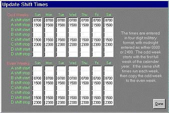
 weeks, each with seven (7) days containing the start and stop times for four (4) shifts each. The times are in 4-digit military format, with midnight entered as 2400.")
24 Update Shift Times The shift times indicate the week to week times that your plant is in operation. The program provides for two (2) weeks, each with seven (7) days containing the start and stop times for four (4) shifts each. The times are in 4-digit military format, with midnight entered as The odd / even week provides a way to run certain shifts one week and different shifts the next week. The odd week is defined as the first full week of the calendar year. The program has default times in it. Sunday through Saturday for both odd and even weeks are set up to run A-shift between 07:00AM and 03:00PM, B-shift between 03:00PM and 11:00PM, and C-shift between 11:00PM and 07:00AM the next day. For a simple example, let's say you run one shift, 08:00AM to 05:00PM, Monday through Friday. You would fill in Monday A-shift start with 0800, A-shift stop with 1700, and repeat these same entries for Tuesday, Wednesday, Thursday and Friday. All the times in Saturday and Sunday would be blank. This has to be entered for both odd and even weeks. A more complex example might be running A-shift from 07:00AM to 03:00PM and C-shift from 03:00PM to 11:00PM one week, then running B-shift from 07:00AM to 03:00PM and D-shift from 03:00PM to 11:00PM the next week. You would fill in the odd week Sunday A-shift start with 0700, A-shift stop with 1500, C-shift start with 1500, C-shift stop with 2300, and repeat these same entries for the rest of the week. Then fill in the even week Sunday B-shift start with 0700, B-shift stop with 1500, D-shift start with 1500, D-shift stop with 2300, and repeat these same entries for the rest of the week. Page 24
25 Page 25


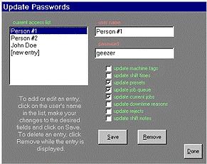
26 Update Passwords Passwords can be entered to restrict access of specific edit functions to certain individuals. For example, John can edit the presets and job queue but Jim can only edit the job queue. If any passwords exist in the password access table for a specific edit function, a password will be requested when anyone tries to access that edit function. To setup the passwords, click on Edit on the menu bar, then passwords in the submenu. The passwords window is displayed with an access window on top of it. The master password has to be entered into the access window, followed by <enter>, to remove it. If an invalid password is entered in the access window, the Access Denied warning sign will be displayed, and you ll have to try again. To enter a new person, click on [new entry] in the access list. The user name can now be replaced with the person s name. Passwords are case sensitive so you ll have to use them just as they are typed in. Click on the edit functions that this person will have access to, and click on Save to store the entry in the access list. To display an entry, click on the person s name in the access list. To update a password, click on the person s name in the access list, made the necessary changes, and click Save. To remove a password, click on the person s name in the access list, and click Remove. Page 26
27 Page 27


28 Change Summary Assignments The fields which appear on the Summary screen are defined here in the Update Summary Assignments window. Each page can have up to four fields. If there are no fields defined for a page, that page is skipped when cycling through the pages on the Summary screen. To change the summary assignments, click Edit on the menu bar, then Summary Assignments in the submenu. Click on the desired Page to display the current field assignments. To change the assignments, click on Change to the right of the field assignment you want to change. The Change buttons are removed, the field being changed is identified, and the fields list is displayed. Select the desired field from the fields list and click Select. The selected field becomes the new field assignment, and the change buttons reappear. Repeat the process to change any other field assignments for the selected page, or select a different page. Page 28

29 When all your changes have been made, click Done to return to the program. Page 29


30 Downtime Reasons Whenever the current cycle of a job surpasses the downtime limit entered, that job is considered down and a downtime event is recorded. A downtime event consists of the date and time the job went down, the date and time the job started running again, and a downtime reason if entered. Down = 8/16/00 6:54:42 AM to 8/16/00 6:59:41 AM..Downtime reason #5 To enter or change a reason for a downtime event, click Edit on the menu bar, then Downtime Reasons in the submenu. Select the machine where the downtime event occurred. The downtime events for that machine, as well as their current downtime reasons will be listed. Select the desired downtime event and click Edit. The selected downtime event will be displayed along with its current downtime reason, highlighted in blue. You can either type in the downtime reason you want, or select from the predefined downtime reasons by clicking on the down arrow to the right, and selecting one of the reasons listed. Page 30


31 The predefined downtime reasons are stored in a file named DowntimeReasons.txt in the host directory. This is a text file that you can create and maintain by using Windows Notepad, or any other text editor. Each line is a separate downtime reason. A sample file should be in the Tracker folder on your host system. When you are satisfied with the reason for the selected downtime event, click Save to store it and return to select another downtime event. Clicking Done before Save will keep the original reason. Click Done to return to the program. Page 31

32 Presets Presets are repeated jobs that have their cycle limits, cavitation, and part weight predefined so that when a job is to be run, you just have to select the job description from the presets list and the program will preload all the applicable fields for you. To enter or change a preset, click Edit on the menu bar, then Presets in the submenu. To add a new preset, click on [new entry] in the presets list. Replace the [new entry] in the description with the job description. The minimum cycle is used to compare against the current cycle to alert if a machine is running too fast. This alert can be disabled by leaving the field empty. The nominal cycle is the time duration of the ideal cycle. This is a required field, and the standard against which the cycle efficiencies are calculated. The maximum cycle is used to compare against the current cycle to alert if a machine is running too slow. The downtime limit is used to compare against the current cycle to alert if a machine has stopped running and is down. Each of these alerts can be disabled by leaving the associated field empty. Each preset can have up to four (4) individual parts with different cavitation and part weight. Only one part is necessary to have a valid preset. After all the appropriate fields have been entered, click Save to add the preset to the list. To edit a preset, click on the desired entry in the presets list. The fields will be filled in with the preset s current settings. Make any desired changes and click Save to store the changes. To remove a preset, click on the desired entry in the presets list, and click Remove. Page 32

33 The Job Queue The job queue is a prioritized list of jobs to be run on a particular machine. The program checks each machine every five (5) seconds to see if a job is currently being run. If not, the program then checks that machine s job queue to see if any jobs are pending. If a job is found, it is removed from the job queue and becomes an active job. Jobs can be entered into the job queue by filling in the required fields, or by recalling a preset. Jobs can be reprioritized at any time while they are in the job queue. To enter or change a job to the job queue, click Edit on the menu bar, then Job Queue in the submenu. To add a new job to the job queue, click on the machine where the job is to be run. The job queue for the selected machine will list the line number, the job s priority in the job queue, and the job description. Click on [new entry] in the job queue list so that it appears in the description field. Click on the description field to highlight the field, and display the Get Preset button, which only appears for a new entry. If you want to load a stored preset, click on the Get Preset button to display the presets list. Selecting a preset from the list will load the preset s stored fields into the job s fields. To enter a job that is not a preset, replace the [new entry] in the description with the job description. The minimum cycle is used to compare against the current cycle to alert if a machine is running too fast. This alert can be disabled by leaving the field empty. The nominal cycle is the time duration of the ideal cycle. This is a required field, and the standard against which the cycle efficiencies are calculated. The maximum cycle is used to compare against the current cycle to alert if a machine is running too slow. The downtime limit is used to compare against the current cycle to alert if a machine has stopped running and is down. Each of these alerts can be disabled by leaving the associated field empty. Each preset can have up to four (4) individual parts with different cavitation and part weight. Only one part is necessary to have a valid job. Page 33
34 The parts requested field is a required field that is not stored in the preset because you never know how many pieces you will need for the same job the next time. If you want to save a [new entry] as a preset, click on the checkbox labeled Save Job as Preset. After all the appropriate fields have been entered, click Save to add the job to the job queue list. The program will automatically assign it as the last job to run. To change priority of jobs in the job queue, select a job from the job list so that its fields are displayed. Change the priority number to the position number in the job queue where this job should be placed. Click Save to reprioritize the job queue. To remove a job from the job queue, select the job from the job list so that its fields are displayed, and click Remove. Page 34

35 Current Jobs To edit the running parameters of a currently active job, click on Edit on the menu bar, then current jobs in the submenu. Select the job from the job list to display the current settings. Make any changes desired, and click Save to store them. To reset a job so that all the counts are reset to zero, click on the Reset button to the right of the part. The word Yes will appear in the button to denote that this part will reset when saved. To close a job so that the next job in the job queue loads, click on the Close button to the right of the part. Again, the word Yes will appear in the button to denote that the job will be closed when the Save button is clicked. Page 35
36 Page 36

37 Enter Rejects and Reasons Since the program does not detect between good and bad parts, the reject counts can be manually entered anytime after the end of the shift. These counts affect the job s stop date, parts to go, hours to go, and material to go. To enter or change rejects and / or reject reasons, click Edit on the menu bar, then Reject Reasons in the submenu. Select the shift file in which the job was running, and the job whose rejects you wish to change. The job s current rejects and reasons will be listed. Select the desired reject to change or [new] and click Edit. The selected reject will be displayed along with its current reject reason. Enter a reject quantity, then either type in the reject reason you want, or select from the predefined reject reasons by clicking on the down arrow to the right, and selecting one of the reasons listed. The predefined reject reasons are stored in a file named RejectReasons.txt in the host directory. This is a text file that you can create and maintain by using Windows Notepad, or any other text editor. Each line is a separate reject reason. A sample file should be in the Tracker folder on your host system. Page 37


38 When you are satisfied with the quantity of rejects and the reason, click Save to store it and return to select another reject count. Clicking Done before Save will keep the original reason. Click Done to return to the program. Page 38

39 Shift Notes Shift notes are messages that are left for the next shift, or just a log of what has been going on. Shift Notes are accessible on any system running the Tracker software. The update the shift notes, click on Edit on the menu bar, and shift notes in the sub menu. Move the mouse inside the text box and click. A cursor should appear where the next character will be inserted. To clear the current shift notes, click on Delete. To return to the program, click on Done. If there are any entries, Shift Notes will appear under the current date, time and shift. The view the current shift notes, click on View on the menu bar, and shift notes in the sub menu. Use the scroll bar on the right to view the entire text. Click Done to return to the program. Page 39
40 Software Debouncers If a particular line is recording multiple counts for a single cycle, chances are that the machine is controlled by older relay logic. As time passes, the relay contacts may start to chatter when opening and closing. This chatter is detected by the Tracker and recorded as individual cycles. To help filter out these false cycles, a software debouncer has been added to the Tracker software. When an electrical transition is detected, no other electrical transitions are acknowledged by the Tracker software for the duration of the debouncer interval. If a debouncer is in effect, its value will be displayed at the bottom of the state times table on the Last 50 Cycles screen. To change the debouncer intervals, display the Last 50 Cycles screen on the host system and type in the word Debouncer. A secondary window should appear with the line number, machine tag, and current debouncer value for each line. Double click on the desired line, and edit the value that appears. Click on Done when you have finished changing the debouncer values. Page 40
INSTALLATION AND OPERATION MANUAL FOR ACC 070 COMM LINK RS485 TO PC INTERFACE AND PRISM SOFTWARE
 SenTech Corporation 5745 Progress Road Indianapolis, Indiana 46241 888/248-1988 FAX 317/248-2014 INSTALLATION AND OPERATION MANUAL FOR ACC 070 COMM LINK RS485 TO PC INTERFACE AND PRISM SOFTWARE ii APPLICABILITY
U-FLASH Setup Guide U-FLASH.
 U-FLASH Setup Guide Thank you for purchasing the U-FLASH. This guide will assist you in the setup of the system. You can call for FREE technical support to get help anytime at 757-258-0910. Please note,
RKAT Audit Trail Module RK-LINK TM Software For the Radio Key 600 Series
 RKAT Audit Trail Module RK-LINK TM Software For the Radio Key 600 Series INSTALLATION & OPERATING GUIDE Rev. B P/N 3321515 www.securakeystore.com (800) 878-7829 sales@securakeystore.com COPYRIGHT 2001
Click Save to return to the main Setup screen.
 ON-SITE Setup Guide Thank you for purchasing the ON-SITE. This guide will assist you in the setup of the system. You can call for FREE technical support to get help anytime at 757-258-0910. Please note,
IS2000. Administrative Operator s Guide. AOG-101 (07/2005) Software Version 7.45
 Software Version 7.45") IS2000 Administrative Operator s Guide www.imron.com AOG-101 (07/2005) Software Version 7.45 Table of Contents INTRODUCTION...6 Overview...6 GENERAL INFORMATION...6 Logging On...7 Logging Off...9 Event
IS2000 Administrative Operator s Guide www.imron.com AOG-101 (07/2005) Software Version 7.45 Table of Contents INTRODUCTION...6 Overview...6 GENERAL INFORMATION...6 Logging On...7 Logging Off...9 Event
ACCESS CONTROL SOFTWARE V3.1 REFERENCE MANUAL
 ACCESS CONTROL SOFTWARE V3.1 REFERENCE MANUAL 01/2004 Centaur is a registered trademark of Position Technology INC. Pro-Report, Tracker, FrontGuard and FrontView are trademarks of Position Technology Inc.
L300 user manual. Programmable DC Electronic Load CONTENTS. Electronic Load Software CAUTION...2 SAFETY NOTES...2
 Programmable DC Electronic Load L300 user manual CONTENTS CAUTION......2 SAFETY NOTES......2 Chapter 1 General Introduction...3 1.1 General Introduction......3 1.2 Specification......3 1.3 Features......3
IS2000. Administrative Operator s Guide
 IS2000 Administrative Operator s Guide Table of Contents Logging Off... 7 Event Manager... 7 HARDWARE MANAGER... 8 Maneuvering the Hardware Tree... 8 Unlocking the Module... 8 Viewing the Hardware Tree...
CO-485USB USB to RS-485 CONVERTER TECHNICAL REFERENCE
 TABLE OF CONTENTS CO-485USB USB to CONVERTER TECHNICAL REFERENCE Specifications, Description and Technical Support... page 1 Connection Diagram... page 2 Set-Up & Testing... page 3 & 4 Power Supply Shunts...
Power Vision 1.5 (Cod )
") ELECTRICAL NETWORK ANALYSIS SOFTWARE Power Vision 1.5 (Cod. 775 353) USER S MANUAL (Cod. M 981 358 / 02 D) 2002 - CIRCUTOR, S.A. INDEX 1.- POWER VISION SOFTWARE INSTALLATION...4 2.- INTRODUCTION TO POWER
ELECTRICAL NETWORK ANALYSIS SOFTWARE Power Vision 1.5 (Cod. 775 353) USER S MANUAL (Cod. M 981 358 / 02 D) 2002 - CIRCUTOR, S.A. INDEX 1.- POWER VISION SOFTWARE INSTALLATION...4 2.- INTRODUCTION TO POWER
Installation & Operation Guide
 Installation & Operation Guide (Shown with optional Override Board Cover) KMD-5831 Programmable Loop Controller PLC-28 Direct Digital Controller 902-019-04B 1 Introduction This section provides a brief
Installation OVERVIEW
 Installation OVERVIEW The DEMCO GATE ACCESS CONTROL SYSTEM is designed to operate up to 4 gates, each with an IN KEYPAD and/or an OUT KEYPAD. Each gate is wired as illustrated in the drawing of a "TYPICAL
PFCS/Qualifier Interface
 PFCS/Qualifier Interface INSTRUCTION MANUAL CE Electronics Inc. 2107 Industrial Drive Bryan, OH 43506 (419) 636-6705 E-mail: sales@ceelectronics.com www.ceelectronics.com PFCS/Qualifier Interface PFCS/Qualifier
DPS INC ASCII MUX. Operation Guide. Table Of Contents. Overview. T/kda
 DPS INC Operation Guide "Your Partners in Telemetry Monitoring Systems" ASCII MUX Fig. - ASCII MUX Expands T/MonXM ASCII s up to Eight Times Table Of Contents Overview... Functional Schematic... Typical
LevelOne. User Manual KVM-0811 / KVM /16-Port PS2 KVM Switch
 LevelOne KVM-0811 / KVM-1611 8/16-Port PS2 KVM Switch User Manual Table of Contents 1. INTRODUCTION...1 FEATURES...1 PACKAGE CONTENT...2 SYSTEM REQUIREMENTS...2 TECHNICAL SPECIFICATIONS...3 FRONT PANEL...4
5 Setting Preferences 15 Preferences 15 Configure Chart Colors 16
 CRITERION Vantage 3 Acquire Training Manual Contents 1 Introduction 3 Collecting Data 3 2 Starting the Program 3 Logging In and Logging Out 3 Logging In 3 Logging in as an Administrator 3 Logging in as
MC4181LV SERIES MASTER CLOCKS
 FN:4181LV.DOC MC4181LV SERIES MASTER CLOCKS TABLE OF CONTENTS INTRODUCTION 2 SPECIFICATIONS 3 INSTALLATION 4 FRONT PANEL DESCRIPTION 4 OPERATION Filling out the Program Record Sheet and Auto-Prompt Display
USER MANUAL. > analyze. reduce. recover
 USER MANUAL > analyze > reduce > recover Table of Contents COPY AUDIT... 1 OVERVIEW... 1 IMPORTANT NOTES FOR PRINT AUDIT 4 CUSTOMERS... 1 COMMUNICATOR TECHNICAL NOTES... 2 COPY AUDIT SOFTWARE... 2 INSTALLING
ADVANCED OPERATOR PANEL (AOP)
") ADVANCED OPERATOR PANEL (AOP) Operating Instructions Issue 04/02 English Contents 1 Warnings and Notes 3 1.1 Special Key Functions 4 2 Applications Examples 4 2.1 Single drive control using the AOP 4 2.2
ADVANCED OPERATOR PANEL (AOP) Operating Instructions Issue 04/02 English Contents 1 Warnings and Notes 3 1.1 Special Key Functions 4 2 Applications Examples 4 2.1 Single drive control using the AOP 4 2.2
Power Vision 1.7 (Cod )
") ELECTRICAL NETWORK ANALYSIS SOFTWARE Power Vision 1.7 (Cod. 775 353) USER S MANUAL (Cod. M 981 358 / 05B) 2005 - CIRCUTOR, S.A. INDEX 1.- POWER VISION SOFTWARE INSTALLATION...4 2.- INTRODUCTION TO POWER
ELECTRICAL NETWORK ANALYSIS SOFTWARE Power Vision 1.7 (Cod. 775 353) USER S MANUAL (Cod. M 981 358 / 05B) 2005 - CIRCUTOR, S.A. INDEX 1.- POWER VISION SOFTWARE INSTALLATION...4 2.- INTRODUCTION TO POWER
4 / 8 / 16 PORT PS2 KVM SWITCH USER S MANUAL
 STACKABLE 4 / 8 / 16 PORT PS2 KVM SWITCH USER S MANUAL PC / Mac / Sun Multi Platform Rev 1.1 TABLE OF CONTENTS INTRODUCTION...1 FEATURES....1 PACKAGE CONTENTS..... 2 TECHNICAL SPECIFICATIONS...3 SYSTEM
3700 SERIES USER MANUAL
 SAFETY GUIDE This manual contains the precautions necessary to ensure your personal safety as well as for protection for the products and the connected equipment. These precautions are highlighted with
Pulsed Frequency TM. Plasma Software Download, Installation and User Guide
 Pulsed Frequency TM Plasma Software Download, Installation and User Guide Contents Account Registration... 3 Create an Account... 4 Download the Software... 6 Install the Software... 9 Connect PLAZOMICS
Intelligent Devices IDI 6005 Speed Sign Controller Technical Manual
 Intelligent Devices IDI 6005 Speed Sign Controller 4411 Suwanee Dam Road, Suite 510 Suwanee, GA 30024 T: (770) 831-3370 support@intelligentdevicesinc.com Copyright 2011, Intelligent Devices, Inc. All Rights
LC3 LIGHTING CONTROLLER OPERATIONS & MAINTENANCE MANUAL 2013 Dec
 LC3 LIGHTING CONTROLLER OPERATIONS & MAINTENANCE MANUAL 2013 Dec THETA LABS INC Aguila AZ 85320-0734 928-671-1885 www.thetalabs.com CONTENTS 1. DESCRIPTION & SPECIFICATIONS page 1.1 General 1 1.2 Mechanical
Chapter Operation Pinout Operation 35
 68000 Operation 35 Chapter 6 68000 Operation 6-1. 68000 Pinout We will do no construction in this chapter; instead, we will take a detailed look at the individual pins of the 68000 and what they do. Fig.
UltraTime Enterprise WebTime User Guide
 UltraTime Enterprise WebTime User Guide This guide will explain how to use the WebTime view of UltraTime Enterprise. Sample screens have been provided for guidance. The WebTime time entry screen is the
GETTING STARTED. Installing the System 2000 Hardware. Configuring Your System 2000 Hardware. Troubleshooting. Configuring Your System 2000 Network
 SYSTEM 2000 GETTING STARTED Installing the System 2000 Hardware Whether you are upgrade an existing System 2, or this is a brand new installation, there will be some hardware installation involved. We
XPD-28 2:8 DMX & RDM Splitter User Manual
 XPD-28 2:8 DMX & RDM Splitter User Manual 2 UM_XPD-28-D0-LEN-V01-00.DOCX 2015-10-26 Index Index... 3 Introduction... 4 Unpacking... 5 Safety Information... 5 Device Overview... 7 Settings and Menu... 9
POWERHOUSE. -- the finest in Digital Command Control -- PRODUCT MANUAL FOR PB-110A TEN AMP POWER STATION
 POWERHOUSE TM -- the finest in Digital Command Control -- PRODUCT MANUAL FOR PB-110A TEN AMP POWER STATION NCE Corporation 1260 CREEK STREET Suite 105 WEBSTER NEW YORK 14580 FAX : (716) 671-9337 E-mail:
version 7.6 user manual
 version 7.6 user manual 2 Copyright JAVS 1981-2014 Table of Contents Introduction... 4 Getting Started... 5 Login... 5 JAVS Publisher 7 Overview... 6 Search Tool Overview... 7 Search Tool-Detailed Operation...
DIABLOSPORT PREDATOR REVISION UPDATE INSTRUCTIONS
 DIABLOSPORT PREDATOR REVISION UPDATE INSTRUCTIONS This page contains instructions that will guide you through the process of updating the DiabloSport Predator to the latest software revision available.
NetworX Series. NX-507E RELAY EXPANDER NX-508E OUTPUT EXPANDER Installation and Startup
 NetworX Series NX-0E RELAY EXPANDER NX-0E OUTPUT EXPANDER Installation and Startup NX-0E / NX-0E AUXILIARY MODULES TABLE OF CONTENTS I. GENERAL DESCRIPTION... II. WIRING INFORMATION... III. NX-0E TERMINAL
Optichrom Advance Application Personal Computer APC 8.0 & 8.1
 Siemens Applied Automation Optichrom Advance Application Personal Computer APC 8.0 & 8.1 Contents Overview 1 APC Hardware Installation 1 Addressing the PCI Board 1 PCI Installations Instructions 3 Board
AP41 / AP81 SERIES TIME SWITCHES
 FN:AP41_81M1.DOC AP41 / AP81 SERIES TIME SWITCHES AP41 AP81 TABLE OF CONTENTS INTRODUCTION 2 SPECIFICATIONS 2 INSTALLATION 5 FRONT PANEL DESCRIPTION 7 OPERATION 8 Filling out the Program Record Sheet 8
ADICON 2500 And C-Max Control Wizard User s Guide
 ADICON 2500 And C-Max Control Wizard User s Guide TABLE OF CONTENTS 1 INTRODUCTION...4 1.1 LEOPARD...4 1.2 OCELOT...4 1.3 C-MAX CONTROL WIZARD...4 1.4 ADICON 2500 MODULES...4 1.4.1 SECU-16...4 1.4.2 SECU-16I...4
Industrial Serial Device Server
 1. Quick Start Guide This quick start guide describes how to install and use the Industrial Serial Device Server. Capable of operating at temperature extremes of -10 C to +60 C, this is the Serial Device
CyberComm Pro 2.4 Data Acquisition Software Installation & User Guide. CyberScan DO 1500
 CyberComm Pro 2.4 Data Acquisition Software Installation & User Guide CyberScan DO 1500 Bench Dissolved Oxygen Meter Technology Made Easy... 68X292341 Rev.0 01/04 PREFACE Thank you for selecting the CyberScan
CONTROL ROOM SOFTWARE
 CONTROL ROOM SOFTWARE Starting QTWatch... Main screen... Control Monitor Screen... Action page... Site Map page... Standard Operations page... Handling calls on Actions... How to log a manual/remote call...
NetworX Series. NX-507E RELAY EXPANDER NX-508E OUTPUT EXPANDER Installation and Startup
 NetworX Series NX-0E RELAY EXPANDER NX-0E OUTPUT EXPANDER Installation and Startup NX-0E / NX-0E AUXILIARY MODULES TABLE OF CONTENTS I. GENERAL DESCRIPTION... II. WIRING INFORMATION... III. NX-0E TERMINAL
Enterprise Voice SUBSCRIBER GUIDE
 Enterprise Voice SUBSCRIBER GUIDE Conterra Networks Enterprise Voice SUBSCRIBER GUIDE 3 TABLE OF CONTENTS Table of Contents Introduction... 6 Logging in... 6 Navigation Bar, Sub-Menu and Page Layout...
First Access Express OPERATOR GUIDE
 First Access Express OPERATOR GUIDE October 2016 Cutting edge simplicity Table of Contents Introduction... 4 PC Requirements... 5 Step 1. Software Installation... 5 Complete Installation Server and Client...
Instructions for Installing FlashUpdate and Downloading Updates for NPRT 2200 Noise Power Ratio Test Set
 Instructions for Installing FlashUpdate and Downloading Updates for NPRT 2200 Noise Power Ratio Test Set Updates to the instrument firmware are available from the Applied Instruments website. Requirements
SIMREX Corporation Your Trusted Wireless Solution Provider
 SIMSYNC Instruction Manual Traffic Controller Time/Date Synchronization/Coordination System Firmware Release 2.5h SIMREX MAN.SIMSYNC, Rev 13.0 FEBRUARY 2008 Your Trusted Wireless Solution Provider www.simrex.com
SMK525 / SMK585 / SMK595
 SMK525 / SMK585 / SMK595 RACK MOUNTABLE 1 / 8 / 16 PORT PS2 KVM SWITCH USER S MANUAL Rev 1.2 TABLE OF CONTENTS INTRODUCTION...1 FEATURES....1 PACKAGE CONTENTS..... 2 TECHNICAL SPECIFICATIONS...3 SYSTEM
The GENIE Light Kit is ideal for introducing simple lighting projects, such as an electronic die, a wearable badge or a night-time warning system.
 Introduction 1 Welcome to the GENIE microcontroller system! The GENIE Light Kit is ideal for introducing simple lighting projects, such as an electronic die, a wearable badge or a night-time warning system.
KEUSB24 PC Keyboard Encoder User Manual
 KEUSB24 PC Keyboard Encoder User Manual Table of Contents Introduction to the KEUSB24 1 Computer Connections and Device ID Jumper 2 Interfacing to the KEUSB24 I/O Header 3 Status LED Connections 4 The
InformationTechnology
 dvanced Calling Features One of the benefits of running University voice service to Skype for Business is the opportunity to manage calls through a PC or laptop using the Skype application with a compatible
Fluke Metrology Software
 Fluke Metrology Software Version 7 MET/CAL 5500/CAL Getting Started Guide P/N 1275404 July 1999 Rev. 2, 9/04 1996-2004Fluke Corporation, All rights reserved. Printed in U.S.A. All product names are trademarks
CAMit I Camera with built in Modem
 CAMit I Camera with built in Modem User s Manual CAMit I AP revision: 3.3 CAMit I Setup revision: 2.0.1 Manual revision: 2.0 Date: February 27, 2002 Congratulations You just acquired a fine product from
Installation Manual GENERAL DESCRIPTION...2 WIRING INFORMATION FOR NX-507 AND NX NX-507 TERMINAL DESCRIPTION...3 NX-507 DRAWING...
 NX-0 RELAY EXPANDER NX-0 OUTPUT EXPANDER Installation Manual GENERAL DESCRIPTION... WIRING INFORMATION FOR NX-0 AND NX-0... NX-0 TERMINAL DESCRIPTION... NX-0 DRAWING... NX-0 TERMINAL DESCRIPTION... NX-0
OMNI Select troubleshooting guide
 OMNI Select troubleshooting guide This guide explains how to recognize and respond to alarms in OMNI Select, how to fix communication loss, perform a loopback test, use ToolKit, and troubleshoot Phason
JNIOR Series 3 A Network I/O Resource Utilizing the JAVA Platform Getting Started Manual Release 3.3 NOTE: JNIOR OS 3.4 or greater required
 JNIOR Series 3 A Network I/O Resource Utilizing the JAVA Platform Getting Started Manual Release 3.3 NOTE: JNIOR OS 3.4 or greater required INTEG Process Group, Inc. 2919 East Hardies Rd, First Floor Gibsonia,
5. LAPTOP PROCEDURES
 5. LAPTOP PROCEDURES Introduction This next section of the user guide will identify core essentials regarding your laptop turning it on, running the program, running the questionnaire, submitting the data,
MX200 SERIES Modbus Card 50P GE Zenith Controls. Operation and Maintenance Manual 50R-2200B 12/00
 g MX200 SERIES Modbus Card 50P-1105 GE Zenith Controls 50R-2200B 12/00 Operation and Maintenance Manual Table of Contents Overview...01 Page LED Indicator...02 Installation...03 Installing the Network
SMK520 / SMK580 / SMK590 RACK MOUNTABLE 1 / 8 / 16 PORT PS2 KVM SWITCH USER S MANUAL
 SMK520 / SMK580 / SMK590 RACK MOUNTABLE 1 / 8 / 16 PORT PS2 KVM SWITCH USER S MANUAL Rev 1.1 TABLE OF CONTENTS INTRODUCTION...1 FEATURES....1 PACKAGE CONTENTS..... 2 TECHNICAL SPECIFICATIONS...3 SYSTEM
DATA LOGGER (Version V1.3)
") WYLER AG Im Hölderli CH-8405 WINTERTHUR Switzerland Tel. 0041 (0) 52 233 66 66 Fax. 0041 (0) 52 233 20 53 Homepage: http://www.wylerag.com E-Mail: wyler@wylerag.com Operating instructions DATA LOGGER (Version
WYLER AG Im Hölderli CH-8405 WINTERTHUR Switzerland Tel. 0041 (0) 52 233 66 66 Fax. 0041 (0) 52 233 20 53 Homepage: http://www.wylerag.com E-Mail: wyler@wylerag.com Operating instructions DATA LOGGER (Version
Sensacell Troubleshooting Guide
 A ONLY SOME MODULES LIGHT UP B PANEL DOES NOT LIGHT UP Only some modules light up Panel does not light up Check jumpers and power wiring AC Power present at Power Supply input terminals? Check AC Line
LockState RL 4000 User Guide
 LockState RL 4000 User Guide www.resortlock.com Table of Contents Section 1: General Overview 1. Foreword... 3 2. Important Information.. 3 3. Software Installation.. 4 Section 2: Initial Lock Setup Manual
CYBERVIEW DVR Troubleshooting Guide
 CYBERVIEW DVR Troubleshooting Guide The DVR will not power up. Symptoms (Power) The DVR is powered up with a message No signal displayed on the screen. The DVR is only showing blue squares where the camera
ETHERNET IRRIGATION CONTROLLER. Irrigation Caddy Model: ICEthS1. User Manual and Installation Instructions
 ETHERNET IRRIGATION CONTROLLER Irrigation Caddy Model: ICEthS1 User Manual and Installation Instructions I R R I G A T I O N C A D D Y M O D E L : I C E T H S 1 User Manual and Installation Instructions
Troubleshooting Unit 10
 Troubleshooting Unit 10 How to Use the Index To use the EagleSoft 15.00 Index, first look for the affected area of the software and then look for the submenu listing. For example, if you wanted to look
TABLE OF CONTENTS Chapter 1 Introduction... 3 Chapter 2 Installation... 7 Chapter 3 Operation... 15
 TABLE OF CONTENTS Chapter 1 Introduction... 3 1.1 Features... 3 1.2 Package Contents... 4 1.3 Technical Specifications... 5 Chapter 2 Installation... 7 2.1 System Requirements... 7 2.2 Cable Diagrams...
DCN Next Generation Synoptic Microphone Control. en Software User Manual LBB 4171/00
 DCN Next Generation Synoptic Microphone Control en Software User Manual LBB 4171/00 About this manual This user manual is divided into five chapters. Chapters 1 and 2 provide background information; chapter
INDUSTRIAL POE SWITCH
 STEP X - Name of Step QUICK START GUIDE LIE1014A, LIE1080A, LIE1082A INDUSTRIAL POE SWITCH 24/7 TECHNICAL SUPPORT AT 877.877.2269 OR VISIT BLACKBOX.COM STEP 1 - Hardware Description LIE1014A LIE1080A TABLE
Power Xpert Meter 2000 Gateway Card Kit
 Quick Start Guide IL02601011E Rev. 2 December 2011 PXM 2250 PXM 2260 IQ 250 IQ 260 Power Xpert Meter 2000 Gateway Card Kit Table of Contents Remove the Meter From Service.... 2 Disconnect Power Connections,
Power Xpert Meter 2000 Gateway Card Kit
 Quick Start Guide IL02601011E PXM 2250 PXM 2260 IQ 250 IQ 260 Power Xpert Meter 2000 Gateway Card Kit Table of Contents Remove the Meter From Service... 2 Disconnect Power Connections, CTs, and Modbus....
Instructions for Installing FlashUpdate and Downloading Updates for Super Buddy Satellite Meter
 Instructions for Installing FlashUpdate and Downloading Updates for Super Buddy Satellite Meter Updates to the Field Guide and to the instrument firmware are available from the Applied Instruments website.
ProHelp EPM. Production & Process Monitoring System. System Administration Manual For ProHelp EPM, Release MANUAL #
 ProHelp EPM Production & Process Monitoring System System Administration Manual For ProHelp EPM, Release 6.1.0 MANUAL #810-0014 Revision B March 23, 2004 ATTENTION You can obtain service support by visiting
Version A For HME System 30
 PC30-60 10/19/98 HME#400373 Rev PC30 Software Version A.1.01 For HME System 30 Installation and Operating Instructions IMPORTANT READ CAREFULLY BEFORE OPERATING SOFTWARE By loading and using this software
Modem Installation and Networking Instructions
 Modem Installation and Networking Instructions P/N 36870 Rev F Introduction The following instructions cover connecting a phone line to an incoming phone source, installing a modem, and setting up a network
Trouble shooting the DeskCNC controller:
 Checking for a functional card. 1) Unplug/Disconnect all connections to the I/O and step and direction pins/terminals. 2) Apply regulated 5vdc to the +5 and gnd terminals. CHECK FOR CORRECT POLARITY WITH
RITIS Training Module 4 Script
 RITIS Training Module 4 Script Welcome to the Regional Integrated Information System or RITIS Module 04 CBT. To begin, select the start button or press Shift+N on your keyboard. This training module will
Full User Manual and Quick Start Guide
 Full User Manual and Quick Start Guide 2 W hile every precaution has been taken in the preparation of this manual, we assume no responsibility for errors or omissions. Neither, is any liability assumed
UC-2000 Installation Manual Unicorn Computers Technology Limited
 UC2000 Installation Manual Copyright 2003. All rights reserved. Table of Contents Specifications 2 Enclosure for the UC2000 Controller 3 Unicorn Access Control System Configuration 4 UC2000 Controller
INSTALLATION DKM-409 NETWORK ANALYSER WITH HARMONIC MEASUREMENT AND SCOPEMETER. Before installation:
 DKM-409 NETWORK ANALYSER WITH HARMONIC MEASUREMENT AND SCOPEMETER The DKM-409 is a precision instrument designed for displaying various AC parameters in 3-phase distribution panels. Thanks to its isolated
ADVANCED DRIVER PROGRAMMING. EVERset User Manual
 ADVANCED DRIVER PROGRAMMING EVERset User Manual User Manual Rev1.4 10/03/2018 Table of Contents 1. Introduction... 2 2. Computer System Requirements... 2 3. Definitions System Definitions... 3 Setting
Electrical Management System (EMS) EMS-HW30C & EMS-HW50C
 EMS-HW30C & EMS-HW50C") Electrical Management System (EMS) EMS-HW30C & EMS-HW50C Installation & Operating Guide for: Model EMS-HW30C Rated at 120V/30A and Model EMS-HW50C Rated at 240V/50A Surgio Says Lifetime Warranty on all
Electrical Management System (EMS) EMS-HW30C & EMS-HW50C Installation & Operating Guide for: Model EMS-HW30C Rated at 120V/30A and Model EMS-HW50C Rated at 240V/50A Surgio Says Lifetime Warranty on all
POWER VISION INSTRUCTION MANUAL
 NETWORK ANALYSIS SOFTWARE POWER VISION INSTRUCTION MANUAL (M98135801-03-11B) CIRCUTOR S.A. INDEX 1.- POWER VISION SOFTWARE INSTALLATION... 4 2.- INTRODUCTION TO POWER VISION... 12 3.- COMMUNICATIONS...
AEXX SERIES MULTI-FUNCTION CLOCK/TIMERS
 FN:XXMFCT1.DOC AEXX SERIES MULTI-FUNCTION CLOCK/TIMERS AEXX SERIES MULTI-FUNCTION CLOCK/TIMERS REV 04/09/09 DESCRIPTION The AEXX Series of Multi-Function Clock/Timers are available with 1, 2.3, 4, 8, or
Trilogy Double-Sided DL5300 Programming Instructions
 345 Bayview Avenue Amityville, New York 11701 For Sales and Repairs 1-800-ALA-LOCK For Technical Service 1-800-645-9440 Publicly traded on NASDAQ Symbol NSSC ALARM LOCK 2008 Trilogy Double-Sided DL5300
Vorne Industries. 2000S Series Serial Input Alphanumeric Display User's Manual
 Vorne Industries 2000S Series Serial Input Alphanumeric Display User's Manual 1445 Industrial Drive Itasca, IL 60143-1849 Telephone (630) 875-3600 Telefax (630) 875-3609 2000S Series Serial Input Alphanumeric
Blue Point Engineering
 Blue Point Engineering Board - Pro Module (E) Instruction Pointing the Way to Solutions! Controller I Version 2.1 The Board Pro E Module provides the following features: Up to 4 minutes recording time
Access Control Unit User s Guide
 NetAXS Access Control Unit User s Guide The configurations described in this document have not been reviewed by Underwriters Laboratories Inc. June 2007 2007 Honeywell. All rights reserved. 800-00233,
Show Designer 1. Software Revision 3.11
 Show Designer 1 Software Revision 3.11 OVERVIEW The Show Designer 1 is a lighting controller based on the successful and simple to use Show Designer. The Show Designer 1 adds to the existing features of
USER MANUAL. MODEL 1225 ParaLink TM Parallel Short Range Modem. SALES OFFICE (301) TECHNICAL SUPPORT (301)
 TECHNICAL SUPPORT (301)") USER MANUAL MODEL 1225 ParaLink TM Parallel Short Range Modem C E R T I F I E D An ISO-9001 Certified Company Part #07M1225-B Doc. #104011UB Revised 9/12/97 SALES OFFICE (301) 975-1000 TECHNICAL SUPPORT
USER MANUAL MODEL 1225 ParaLink TM Parallel Short Range Modem C E R T I F I E D An ISO-9001 Certified Company Part #07M1225-B Doc. #104011UB Revised 9/12/97 SALES OFFICE (301) 975-1000 TECHNICAL SUPPORT
ESPSX3 Ethernet Serial Port Server X 3 Users Guide
 ESPSX3 Ethernet Serial Port Server X 3 Users Guide The ESPSX3 is an Ethernet Serial Port Sever with two RS-232 ports and one port that can be configured for RS-232, RS-485, or RS-422. The RS-485/RS-422
KE-USBMX20. Matrix Keypad Interface User Manual
 KE-USBMX20 Matrix Keypad Interface User Manual Table of Contents Introduction to the KE-USBMX20 1 Computer Connection 2 Interfacing to the KE-USBMX20 Header 3 Status Feedback LED 4 The KE-USBMX20.EXE Program
Rev. A. ANC Series RS-485/RS-422 Synchronous Clock Display. Antona Corporation (818) URL:
 URL:") Rev. A ANC - 7020 Series RS-485/RS-422 Synchronous Clock Display Antona Corporation, Los Angeles, CA Antona Corporation (818)783-4299 URL:http://www.antona.com 1 Antona Corporation Copyright Copyright
Rev. A ANC - 7020 Series RS-485/RS-422 Synchronous Clock Display Antona Corporation, Los Angeles, CA Antona Corporation (818)783-4299 URL:http://www.antona.com 1 Antona Corporation Copyright Copyright
User s manual 19 1U RACKMOUNT CONTROL CENTER. Rack-KVM in-1 TABLE OF CONTENTS INTRODUCTION... (KVM switch, Keyboard, LCD display, touch pad)
") Rack-KVM9000 User s manual 4-in-1 (KVM switch, Keyboard, LCD display, touch pad) 19 1U RACKMOUNT CONTROL CENTER Rev 1.1 TABLE OF CONTENTS INTRODUCTION... FEATURES.... PACKAGE CONTENTS..... TECHNICAL SPECIFICATIONS...
Rack-KVM9000 User s manual 4-in-1 (KVM switch, Keyboard, LCD display, touch pad) 19 1U RACKMOUNT CONTROL CENTER Rev 1.1 TABLE OF CONTENTS INTRODUCTION... FEATURES.... PACKAGE CONTENTS..... TECHNICAL SPECIFICATIONS...
Scheduling Module Client Booking Quick Guide Online-Scheduling
 Scheduling Module Last Updated: November 26, 2009 System Administration Contact: Colin Bryant Phone: 604-822-7374 E-mail: PsychIT@exchange.ubc.ca Logon to Book King Enter the following URL into your address
ICPDAS FSM-510G Series Ethernet Management Switch Quick Start
 ICPDAS FSM-510G Series Ethernet Management Switch Quick Start Version 1.0, Dec 2014 Overview The Management Ethernet Switch solutions are designed for supporting standard industrial applications. Managed
Trilogy DL3200 Programming Instructions
 345 Bayview Avenue Amityville, New York 11701 For Sales and Repairs 1-800-ALA-LOCK For Technical Service 1-800-645-9440 Publicly traded on NASDAQ Symbol NSSC ALARM LOCK 2008 Trilogy DL3200 Programming
RAIN BIRD RC-4Bi, RC-7Bi, RC-1260Bi SERIES INSTRUCTION MANUAL
 RAIN BIRD RC-4Bi, RC-7Bi, RC-1260Bi SERIES INSTRUCTION MANUAL DESCRIPTION OF CONTROLS Refer to Figure 1 Figure 1 A. HOUR DIAL with 23 CYCLE START PINS The HOUR dial contains 23 pins for rescheduling automatic
Scheduler User Guide. Version 6
 Scheduler User Guide Version 6 Scheduler Program and User Guide 2003 Emergency Medicine Informatics, LLC. All rights reserved. 2 Introduction...7 The Scheduling Process...7 Shift Description...8 On Call
T Series BIOS BIOS SETUP UTILITY
 BIOS SECTION T4010 LifeBook T Series Tablet PC T Series BIOS BIOS SETUP UTILITY The BIOS Setup Utility is a program that sets up the operating environment for your tablet. Your BIOS is set at the factory
Instruction Manual. Electrical Management System (EMS) EMS-HW30C & EMS-HW50C
 EMS-HW30C & EMS-HW50C") Instruction Manual Electrical Management System (EMS) EMS-HW30C & EMS-HW50C EMS-HW50C EMS-HW30C! CAUTION These instructions are intended to provide assistance with the installation of this product, and
Instruction Manual Electrical Management System (EMS) EMS-HW30C & EMS-HW50C EMS-HW50C EMS-HW30C! CAUTION These instructions are intended to provide assistance with the installation of this product, and
INSTALLATION PROCEDURE FOR THE INNOVEC IPT POWERED PRINTING TOTALISOR
 INSTALLATION PROCEDURE FOR THE INNOVEC IPT POWERED PRINTING TOTALISOR Suite 5, 56-6 Chandos Street, St. Leonards NSW 065/PO Box 35 Spit Junction NSW 088 Australia Phone +6 9906 758 www.innovec.com page
TPWINLOG V TPWINLOG V-2016 LFa is the latest release
 TPWINLOG V-2016 1.0 This program is provided to "friends" of W4AXO free of charge and is worth at least what it cost. No warranty is offered or implied. Questions or comments may be addressed to W4AXO@arrl.net.
SYNERGY GLOBAL INC. Toll Free : Fax :
 SYNERGY GLOBAL INC Toll Free : 1-888-865-6888 Fax : 510-226-8968 Email : info@rackmountmart.com LCD1U15-03 series & LCD1U17-10 series User s manual 4-in-1 (KVM switch, Keyboard, LCD display, touch pad)