D1260/D1260B. Owner's Manual. Keypad
|
|
|
- Tabitha Harmon
- 5 years ago
- Views:
Transcription
1 D1260/D1260B EN Owner's Manual Keypad
2 D1260/D1260B Owner's Manual This system includes a telephone line seizure feature. The system may be programmed to communicate with a central monitoring station to report system events. You will not be able to use your phone while the system is communicating with the central monitoring station. In the unlikely event that the central station is not able to receive the report, your phone may be unavailable for up to 20 minutes while the panel makes additional communication attempts. Some commands listed below may not be available. Contact your security company for more information. Contents Introduction...5 Your Keypad...5 About This Owner s Manual...6 Part I: Security system basics...7 Using the keypad...7 Command center keys...7 Points 8 What is a Point?...8 Controlled Points Hour Points...8 Your Custom Display...8 View Faulted or Bypassed Points...9 To automatically scroll faulted or bypassed points...9 Warning Displays and Tones...10 Keypad Quiets for Keystrokes...10 Priority of Events...10 Fire Alarms...11 Silencing Fire Alarms...11 Burglary Alarms...12 Silencing Burglary Alarms...12 Fire Trouble and Fire Supervisory Events...13 Silencing Fire Trouble and Fire Supervisory conditions 13 Special Fire Trouble and Fire Supervisory Display...13 Viewing Fire Trouble and Fire Supervisory conditions 13 Non-Fire Trouble and Supervisory Events...13 Silencing Non-Fire Trouble and Supervisory Events.13 Special System Trouble Display...13 Cleared Events Are Not Lost...13 Entry Delay Tone and Display...14 Exit Delay Tone and Display...14 Keystroke Checking Tones...14 Silencing an Alarm...14 To SILENCE an alarm:...14 How Your System Reports Alarms...14 Part II: System Commands Entering a Passcode Turning On the System (Arming) To Turn Your Security System On (Arm): Turning Off the System (Disarming) To Turn Your Security System Off (Disarm): Turning On the System (Arming) With a Duress Passcode Turning On the System (Arming) With Doors or Windows Open MASTER ARM? (COMMAND + 1) Description Using Master Arm: Master Arming all Areas MASTER ARM INST? (COMMAND ) PERIMETR INST (COMMAND + 2) Turn On the Perimeter With No Delays Using Perimeter Inst: PERIMETR DELAY? (COMMAND + 3) Turn On the Perimeter With Delays Silence the Trouble Sounder & Clear Trouble Display (COMMAND + 4) Description Using COMMAND 4: VIEW MEMORY? (COMMAND ) View Event Memory Using View Memory: WALK TEST? (COMMAND ) Walk Test RESET SENSORS? (COMMAND ) Reset Sensors Using Reset Sensors: WATCH MODE? (COMMAND + 6) Watch Mode Entering Watch Mode: Exiting Watch Mode: PERIMETR PART? (COMMAND + 8) Partially Turn On the Perimeter Using Perimetr Part: Bosch Security Systems 9/ D
3 D1260/D1260B Owner's Manual Contents Special Alerts (COMMAND + 7 and COMMAND + 9) 30 Using COMMAND 7:...30 Using COMMAND 9:...31 Part III: Advanced Commands...32 Advanced Commands...32 Terms Used in This Section...32 BYPASS A POINT? (COMMAND + 0)...33 Description...33 Using Bypass a Point...33 UNBYPASS A POINT? (COMMAND )...35 Description...35 Using Unbypass a Point:...35 SEND REPORT? (COMMAND or 4+2)...36 Description...36 Using Send Report...36 REMOTE PROGRAM? (COMMAND )...38 Description...38 For systems without a phone number...38 For systems with a phone number or network connection...39 CHANGE TIME/DATE (COMMAND )...40 DOOR CONTROL (COMMAND )...41 Description...41 Using Door Control...41 Access Level...43 CHANGE DISPLAY (COMMAND )...44 Brighten/Dim Display...44 Show Continuous Time/Date...44 EXTEND CLOSING (COMMAND )...45 CHG SKEDS? (COMMAND )...47 Description...47 Using Chg SKEDS...47 DEL USER? (COMMAND )...50 CHG RELAYS? (COMMAND )...51 CHG PASSCODES? (COMMAND )...51 Description...51 Using Chg Passcodes...52 ADD/CHANGE USER (COMMAND )...53 DEFAULT TEXT? (COMMAND )...60 FIRE TEST? (COMMAND )...61 DISPLAY REV? (COMMAND )...62 SERVICE MENU? ( Enter)...63 Using View Log...64 Using Print Log...65 Using Display Rev...65 Using Service Walk Test...65 Using Default Text Using Setup Part IV: Multi-Area Use Working with Multiple Areas from a Single Command Center 68 View Area Status View Point Status MOVE TO AREA? (COMMAND ) Turning On the System Turning on Selected Areas Turning on Multiple Areas with a Passcode Faulted Points in Other Areas Turn On the Entire System Without Delays Turning on All or Selected Areas Turning Off the System Turning Off Multiple Areas with a Passcode Turning Off Multiple Areas with Disarm All Turning Off Selected Areas Appendix Supplementary Information for Adding Passcodes User Authority Levels Passcode Worksheet User Interface User Interface User (Passcode) Worksheet (User 000 to 038) User (Token) Worksheet (User 000 to 038) D9412G/D7412G Only User (Passcode) Worksheet (User 039 to 075) User (Token) Worksheet (User 039 to 075) D9412G/D7412G Only User (Passcode) Worksheet (User 076 to 114) ( = D9412G only) User (Token) Worksheet (User 076 to 114) D9412G/D7412G Only ( = D9412G only) User (Passcode) Worksheet (User 115 to 150) ( = D9412G only) User (Token) Worksheet (User 115 to 150) ( = D9412G only) User (Passcode) Worksheet (User 151 to 189) ( = D9412G only) User (Token) Worksheet (User 151 to 189) ( = D9412G only) User (Passcode) Worksheet (User 190 to 226) ( = D9412G only) User (Token) Worksheet (User 190 to 226) D9412G/D7412G Only ( = D9412G only) User (Passcode) Worksheet (User 227 to 249) ( = D9412G only) Bosch Security Systems 9/ D 3
4 D1260/D1260B Owner's Manual Contents User (Token) Worksheet (User 227 to 249) ( = D9412G only)...91 User (Passcode) Worksheet (Blank)...92 User (Token) Worksheet (Blank)...93 Security System Limitations...93 Fire Safety and Evacuation...94 Standard Displays...95 System Trouble Displays...96 Security System Glossary...98 Maintenance and Service...99 How to Clean the Command Center...99 Your Alarm Company...99 Figures Figure 1: D1260/D1260B front panels...5 Figure 2: D1260/D1260B Digital Keypad...6 Figure 3: Using soft keys for display menus...6 Figure 4: Smoke Detector Locations (Plan View)..94 Figure 5: Smoke Detector Locations (Elevation View)...94 Figure 6: Escape Route...94 Tables Table 1: D1260/D1260B Keypad keys...7 Table 2: Keypad Commands...15 Table 3: Door Status...42 Table 4: Sked Table...49 Table 5: Screen Area Definitions Bosch Security Systems 9/ D
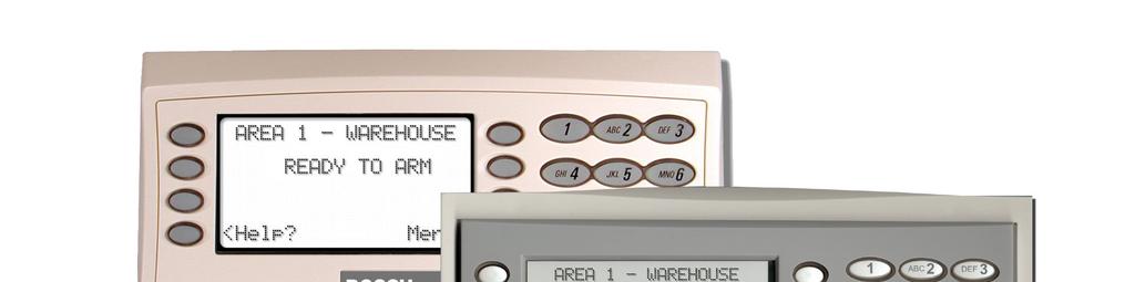
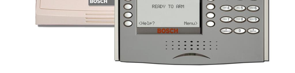
5 D1260/D1260B Owner's Manual Contents Introduction Your security system helps to secure life, property, and investments against fire, theft, and bodily harm. The keypad is an advanced digital device that offers a variety of features not available with other systems. Its highly visible, backlit keypad and built-in sounder alert you to a number of system events. A familiar ATM style design and ease-of-use make it ideal for property monitoring. Your Keypad Your Keypad is composed of two main sections: the numeric keypad section and the display/selection keys (also referred to as soft keys ). Figure 1: D1260/D1260B front panels 1 D1260B 2 1 D # LCD Display 2 - Digital Keypad 3- Soft Keys 4 - Keypad Function Keys Bosch Security Systems 9/ D 5

6 D1260/D1260B Owner's Manual Introduction - About This Owner s Manual The numeric keypad section is a standard 3x4-keypad matrix that should be very familiar to you. It has been designed to closely resemble that of a standard telephone with the numeric keys of 1-0; and * and # keys. The display is an easy-to-read 4 line by 20- character liquid crystal display that becomes backlit when a key is pressed or a system event occurs. Figure 2: D1260/D1260B Digital Keypad D1260 # D1260B The soft keys are used to make selections when the display shows an arrow pointing next to it. For example, the display shown to the right is what will appear when there are faulted points in your system. Pressing the soft key adjacent to the View Points> display will then begin to scroll the faulted point(s) in your system. Advanced Commands: Allow users to perform advanced system functions like add and delete user passcodes, reassign authority levels to user passcodes and operate or change programmed scheduled events (Skeds) from the keypads. As you make changes to the system, update the information contained in the tables in this guide to provide an accurate account of the programmed information. Multi-Area Use: Each of the functions described in the preceding section on Advanced Commands is presented as though your system includes only one area. If your system includes more than one area, it can be set up one of two ways by the installing company: (1) Each keypad will only have access to the local area to which it is assigned, or (2) Each keypad may access either some or all areas beyond the one to which it is assigned. Appendix: Covers the limitations of a Security System, Fire Safety and Evacuation, Maintenance and Service of your Security System and How to Clean the Keypad. Figure 3: Using soft keys for display menus About This Owner s Manual This owner s manual is divided into five main sections: Security System Basics: Covers how to use the Keypad, the various keys on the Keypad, what a Point is and the various types of Points, and custom displays. System Commands: This section covers system commands, such as turning the system on and off, resetting sensors, etc. Your security company programs the functions described in this section. Some of them may not be included in your system. Some of the functions covered may require you to enter your personal passcode. 6 Bosch Security Systems 9/ D

7 D1260/D1260B Owner's Manual Part I: Security system basics Part I: Security system basics Using the keypad Your security system provides quick access to functions by pressing the COMMAND key and one or two additional keys. Pressing the soft key adjacent to the function being displayed initiates the function. D1260 D1260B Another way to access functions is through the Command Menu. To access the Command Menu, press the soft key adjacent to Menu> shown in the display. To exit the Command Menu, press the <Exit soft key. Use the Command Menu to locate functions you don t use often or that don t have a command number. Pressing the <Previous or Next> soft key while in the Menu List allows you to scroll up or down through the list of functions programmed by your security company. Command center keys Table 1: D1260/D1260B Keypad keys Key D1260 D1260B Name COMMAND Description Use the COMMAND key in combination with one or two numeric keys to perform a function # ENTER The ENTER key is used to complete the entry of your passcode at the command enter. Whenever a function requires that you enter your passcode at the keypad, first press the digits of the code and then press the ENTER key. Your system will not recognize your passcode until you press ENTER. EXIT When Exit> or <Exit appears in the keypad display, pressing the soft key adjacent to it will bring you one level up in the function or will exit you out of the function you are in.these functions may be displayed on either side of the display. Previous When viewing a list, pressing the <Previous soft key will take you back to the previously shown item. Next Press the Next> soft key to pass over the present item(s) in a menu or function. Bosch Security Systems 9/ D 7
8 D1260/D1260B Owner's Manual Part I: Security system basics - Points Points What is a Point? A point is a detection device, or group of devices connected to your security system. Points display individually at the keypad with custom text. The text can describe a single door, motion sensor, smoke detector, or an area such as UPSTAIRS or GARAGE. There are two basic types of points, controlled and 24- hour. Controlled Points Controlled points respond to alarm conditions depending upon whether the system is turned on (armed) or turned off (disarmed). Controlled points are programmed to respond instantly to alarm conditions or to provide a delay for you to reach the keypad and disarm the system. The type of alarm appears before the point text when there is an alarm. There are two types of controlled points, perimeter points and interior points. Perimeter Points These points usually include all exterior doors and windows of the building. Interior Points These points usually include interior forms of burglary detection devices, such as motion sensors, or inside doors, for example. 24-Hour Points 24-hour points are always on, even when the burglary system is disarmed (turned off). There are two types of 24-hour points, fire points and non-fire points. Fire Points Fire points exclusively monitor fire detection devices. They are always armed and cannot be disarmed. You can clearly distinguish fire points from other non-fire points at the keypad. When there is a fire alarm, the display shows the following: *FIRE ALARM* is displayed on the first line, text identifying the point as a fire point is displayed on the second line, and instructions for silencing the alarm are displayed on the third and fourth lines. Fire alarms have a unique audible warning signal. Non-Fire Points Non-fire 24-hour points are always armed and cannot be disarmed. Your Custom Display At an idle state means that the system is not currently performing a function entered by a user. There are three idle states the system may be in: Turned on (Armed) Turned off (Disarmed) with no points faulted (doors or windows open) in the area Turned off with faulted points (doors or windows open) in the area. 8 Bosch Security Systems 9/ D
9 D1260/D1260B Owner's Manual Part I: Security system basics - View Faulted or Bypassed Points This manual uses the default idle state displays for examples of these idle states. Your security company may have programmed custom text for the idle displays in your system. The custom text and the default text for the three system idle displays follow. Area Name Text Appears on the top line of the display Default Text Custom Text Throughout this manual, all examples of AREA # NAME TEXT will use AREA 1 WAREHOUSE. The actual name of Area 1 will differ depending on the specifics of your system. Area Is On Text The Silence> soft key is only shown when the keypad buzzer is active Area Off Text Indicates the area is turned off (disarmed). 24-hour points remain armed. Area Not Ready Text Indicates that the area is turned off, but not ready to arm. View Faulted or Bypassed Points To properly arm your system, all the doors and windows in the system must be in the normal (not faulted) condition. Viewing the faulted points helps you find faulted points and correct them so proper arming is possible. Your keypad offers two ways of displaying faulted and bypassed point information. The first causes the faulted or bypassed point information to scroll automatically through the display. The second allows you to manually scroll through each individual point description. To automatically scroll faulted or bypassed points 1. Ensure your keypad shows idle text. 2. Press any number key. The text for Area 1 is displayed first followed by the number (#) of faulted points on the next line 3. The display changes to show the point text description of the faulted points. If there is more than one faulted point, the display will automatically cycle through all of them before returning to idle text. These displays scroll at the rate of 3 seconds each. The View Points> soft key may be displayed on the third line of the keypad if there are faulted points. Bosch Security Systems 9/ D 9
10 D1260/D1260B Owner's Manual Part I: Security system basics - Warning Displays and Tones 4. The display returns to idle text after scrolling through the faulted and bypassed point information. The View Points> soft key will be shown when there are faulted points. To manually scroll faulted or bypassed points: 5. Ensure your keypad shows idle text. 6. Press the View Points> soft key to display the first faulted point. Press the Next> soft key or the <Previous soft key repeatedly to display the faulted and bypassed point information. If faulted or bypassed points in other areas exist, then the display changes to show these points before returning to idle text. Warning Displays and Tones Your keypad emits one of several distinct tones and displays custom text to alert you to system events. Additional bells or sirens may also be connected to your system. Bells or sirens mounted on the exterior of your premises alert neighbors to emergencies and provide an audible guide for police and fire fighters. Keypad Quiets for Keystrokes Pressing any key on the keypad lights the keys and quiets any warning tones. If you don t press another key within 20 seconds, the keypad lights go out and the warning tones resume. Priority of Events If more than one event occurs, your system sorts them into one of four groups. The groups (highest priority first) are: Fire Alarms Burglary Alarms Fire Troubles and Fire Supervisory conditions Non-Fire Troubles and Non-Fire Supervisory conditions. The group with the highest priority scrolls first in the keypad s display. Descriptions of the tones and displays for each group and instructions for silencing the tones are included in the descriptions that follow. 10 Bosch Security Systems 9/ D
11 D1260/D1260B Owner's Manual Part I: Security system basics - Fire Alarms Fire Alarms Fire alarms are the highest priority events. When a fire point activates, your keypad emits a pulsating highpitched fire tone. Evacuate all occupants and investigate for smoke or fire. Ensure that all occupants know the difference between the burglary tone and the fire tone. The tone sounds for the time set by your security company. Silencing Fire Alarms Entering a personal passcode with the proper authority level silences a fire alarm and disarms the system if it was armed. The system will now display *Alarm Silenced* on the second line and Clear Display> appears on the fourth. Then the number of points in alarm (# FIRE ALARMS) and then the area text appears (AREA 1 NAME TEXT) followed by the custom text of all the points in alarm (SMOKE DETECTOR), in the order of occurrence. If there is more than one point causing an alarm, the display will show each point for three seconds before showing the next one. When the last alarm is shown, the next display is the idle text. The cycle is repeated until COMMAND 4 is pressed. Your system may be programmed so that you cannot silence some fire alarms until the fire event clears. Entering COMMAND 4 clears the scrolling point text from the display. The *Alarm Silenced* message will continue to alternate with idle text as a reminder that it is still possible to view the text of the points in alarm by using the View Memory function. See VIEW MEMORY? (Command 40) for more information. To clear the event memory and remove the *Alarm Silenced* message from the display, press the Clear Display> soft key. The display will show the instructions for clearing the message. Enter a valid passcode and press the Clear> soft key. If a fire trouble still exists after acknowledging the alarm, the display shows Fire Trouble. 3 seconds 3 seconds 3 seconds To remove this display, the fire point(s) must be returned to normal. If you wish to review cleared events, use COMMAND seconds Bosch Security Systems 9/ D 11
12 D1260/D1260B Owner's Manual Part I: Security system basics - Burglary Alarms Burglary Alarms Burglary alarms are the second priority. When a burglary point activates while your system is armed, your keypad emits a steady high-pitched burglary tone. The tone sounds for the time set by your security company. The keypad display shows the number of burglary points activated, the point text then idle text. Silencing Burglary Alarms Entering a personal passcode with the proper authority level silences a burglary alarm and disarms the system if it was armed. The system will now display *Alarm Silenced* If there is more than one point causing an alarm, the display will show each point for three seconds before showing the next one. When the last alarm is shown, the next display is idle text followed by the first alarm and then the number of points in alarm ### Alarms and the custom text of all the points in alarm, in the order of occurrence. 3 seconds 3 seconds 3 seconds Entering COMMAND 4 clears the scrolling point text from the display. The *Alarm Silenced* message will continue to alternate with idle text as a reminder that it is still possible to view the text of the points in alarm by using the View Memory function. See VIEW MEMORY? (Command 40) for more information. 3 seconds To clear the event memory and remove the *Alarm Silenced* message from the display, press the Clear Display> soft key. The display will show the instructions for clearing the message. Enter a valid passcode and press the Clear> soft key. 12 Bosch Security Systems 9/ D
13 D1260/D1260B Owner's Manual Part I: Security system basics - Fire Trouble and Fire Supervisory Events Fire Trouble and Fire Supervisory Events When a fire trouble or fire supervisory condition occurs, your keypad emits three warble tones, then a pause (repeatedly). The system displays the number of fire points that are in a trouble or supervisory condition as well as the point text of the affected points. Silencing Fire Trouble and Fire Supervisory conditions Pressing COMMAND 4 or the Silence> soft key silences the conditions. In addition to this, entering a personal passcode with the proper authority level silences the condition and disarms the panel if it was armed. If you wish to review these cleared troubles, using COMMAND 40 can do this. Some systems may be programmed to automatically re-sound the keypad s trouble tone after a period of time if the fire trouble or fire supervisory condition remains. Consult your security company for further information. Special Fire Trouble and Fire Supervisory Display If you silence the keypad or clear a trouble or supervisory condition for a Fire Point from the display and the fire point remains in trouble, Fire Trouble or Fire Supervisory appears in the keypad s display. This remains in the display until the condition causing the trouble is cleared. Some fire points, when tripped, will display FIRE TROUBLE for a preset amount of time. If no other fire activity is detected, this condition will automatically clear. If the condition remains or another fire detector is tripped, a fire alarm will occur. Viewing Fire Trouble and Fire Supervisory conditions After pressing COMMAND 4 or entering your passcode, the text of the fire point in trouble continues to automatically scroll through the display. Press View Points> soft key and then Next> soft key to scroll these displays manually if you wish. Events scroll in chronological order. Non-Fire Trouble and Supervisory Events When a trouble event occurs, your keypad may be programmed to emit three warble tones, then a pause (repeatedly). If the system was armed the keypad display shows the number of non-fire trouble events or non-fire supervisory events and then custom text for each activated point. Silencing Non-Fire Trouble and Supervisory Events Pressing COMMAND 4 or the Silence> soft key silences the Trouble and/or non-fire Supervisory conditions. In addition to this, entering a personal passcode with the proper authority level silences a trouble and disarms the panel if it was armed. Press the View Points> soft key then the Next> soft key to scroll these displays manually. If you wish to review these cleared troubles, use COMMAND 40 to do this. Special System Trouble Display These displays appear on all keypads in the system. See Standard Displays for a description of each system trouble display. Entering your passcode, COMMAND 4 or pressing the Silence> soft key will silence a system trouble tone, but the System Trouble display will not clear until the faulted condition is corrected. A system trouble display begins by sounding a trouble tone and then three seconds later the specific System Trouble Display is shown, such as Service AC Fail. Some system may be programmed to not initiate a trouble tone during these conditions. Cleared Events Are Not Lost If you clear the alarms and troubles from the display, you can still view all the events that occurred since the last time the system was armed by using COMMAND 40 (View Event Memory). Bosch Security Systems 9/ D 13
14 D1260/D1260B Owner's Manual Part I: Security system basics - Silencing an Alarm Entry Delay Tone and Display When you enter an armed system through a point programmed for entry delay, the keypad emits a repeating warble tone and displays the following to remind you to turn off your security system. To SILENCE an alarm: Enter your passcode and press ENTER. If you fail to turn off the security system before the entry delay time expires, it may sound the burglary tone and may also send an alarm report to your security company. Exit Delay Tone and Display After you arm your system, the keypad emits a repeating beep tone, displays AREA 1 NAME TEXT is now arming then How Your System Reports Alarms Your security system may be programmed to automatically disconnect your telephones when sending reports to your security company. Once the report is completed, your security system returns the telephones to normal operation (check with your security company). Other methods of communicating alarm conditions are also available. Please consult your security company for services available in your area. Your system makes repeated attempts to send reports to your security company. In the event your security system fails to communicate, the keypad sounds a Trouble Tone and displays AREA 1 WAREHOUSE Comm Fail Route Grp1 (where the Route Group can be 1, 2, 3, or 4): EXIT NOW! and counts down the exit delay time. Keystroke Checking Tones Valid Entry If you press an appropriate key for the function or entry you desire, the keypad emits a muted beep tone, indicating it accepted your keystroke. Invalid Entry A flat buzz tone sounds when you perform a function that is not allowed or when the keypad has no information to display. Silencing an Alarm The audible alarm sounds for a specific period of time before it automatically shuts off. If an alarm occurs and you want to silence the siren before the time expires, simply enter your personal passcode and press ENTER. Notify your security company of the communications failure. If your system uses telephone lines as its means of communication and telephone service is interrupted, your security system cannot send reports to your security company unless it has an alternate means of transmitting them. 14 Bosch Security Systems 9/ D
15 D1260/D1260B Owner's Manual Part II: System Commands - Entering a Passcode Part II: System Commands Below is a summary of the commands covered in this section. Some of these functions may not be available in your system. Please consult your security company to determine which commands have been made available to you. If you attempt to enter a function that s not available or if the function is available in the system but your passcode is not authorized to perform the function, then **No Authority** will display on the Keypad. Press the COMMAND key and then the one or two digits shown in the table below to perform the function. When you use a command to perform a function, the displays in the function list below do not appear at your keypad. Some commands listed below may not be available. Contact your security company for more information. Table 2: Keypad Commands COMMAND Function Master Arm Master Arm Instant Perimeter Instant Perimeter Delay Silence Trouble Sounder & Clear Trouble Display View Memory Walk Test Reset Sensors Watch Mode Special Alert Perimeter Partial Special Alert Walk Test Entering a Passcode 1. The display may prompt you to enter your passcode. 2. The passcode is shown as asterisks (*) when entered and advance from the right side of the display to the left until all passcode digits (from a minimum of 3 to a maximum of six) are entered. 3. Press ENTER. Bosch Security Systems 9/ D 15
16 D1260/D1260B Owner's Manual Part II: System Commands - Turning On the System (Arming) Turning On the System (Arming) Your security system can be turned on (armed) in many different ways, depending on the arming command used. Arming Commands are those commands used to turn on the system. The most basic arming command is to arm the entire system. The simplest way to arm your system is to enter your personal passcode or press [COMMAND] [1]. There are several other arming commands to turn on the system. These are described later in this manual. To Turn Your Security System On (Arm): 1. Enter your passcode and press ENTER. 2. The keypad briefly displays AREA 1 NAME TEXT is now arming, Turning Off the System (Disarming) Entering your personal passcode turns off your security system. When the system is turned on, you must enter through a designated entry door to prevent an instant alarm condition. Opening the door starts entry delay time and the Keypad emits a pulsing beep tone to remind you to turn off the system. Enter your passcode before the delay time expires and the system will turn off. If you enter through the wrong door or fail to disarm before the entry delay time expires, you will cause an alarm. If this happens, silence the alarm (by entering your personal passcode and pressing ENTER) and call your security company to let them know that it is not an emergency situation. To Turn Your Security System Off (Disarm): 1. Enter your passcode and press ENTER. and the exit delay tone begins. After exit delay time expires, 5. You must press the ENTER key within 5 seconds of entering your passcode, or the passcode entry will be invalid. 6. The display returns to idle disarmed text. the display changes to idle armed text. Turning On the System (Arming) With a Duress Passcode Your passcode may have a special duress feature that is simply your personal passcode with its last digit increased by 1 or 2. If an intruder demands that you arm or disarm the security system, you can use your duress passcode. The duress passcode arms or disarms the system and sends an alarm report to your security company. There is no alarm tone or visual indication at the premises that the report is sent. Check with your security company before attempting to use this feature. 16 Bosch Security Systems 9/ D
 that are force armed are not included in the system.")
17 D1260/D1260B Owner's Manual Part II: System Commands - Turning On the System (Arming) With Doors or Windows Open Turning On the System (Arming) With Doors or Windows Open If a protected door or window is open, you may have the option of force arming with that point faulted. Faulted points (opened doors or windows) that are force armed are not included in the system. The remaining points arm normally. Force armed points either return to normal operation after you turn off your system or return to normal when the door or window is closed. Your system might not offer force arming or it may be restricted to specific points. Contact your security company for more information. 1. Use your passcode or an arming function to start the arming process. 7. The display shows Check Area #. Indicates that more than the number of allowable points are faulted. Bypassed points are counted as faulted. Your system s maximum number of bypassed and/or force armed points is set by your security company. Check with them to learn this number. 9. The display shows AREA 1 WAREHOUSE Not Ready to Arm. 8. One of the messages below may display in place of Check Area #. 10. Pressing the View Points> soft key will show the specifics for any points that are faulted, if any, and bypassed, if any. Faulted points are displayed first then bypassed points. 11. The display changes to show the number of faulted points in the area. Indicates the system is programmed not to arm with particular points faulted (doors or windows open). Indicates that the system s number of allowable bypassed points has been reached. Your system s maximum number of bypassed and/or force armed points is set by your security company. Check with them to learn this number. Press Next> soft key repeatedly to scroll through the point text for each faulted point. If you do not want to go through the list of faulted points and want to go directly to the Force Arm> soft key or Force Bypass> soft key, press the COMMAND button. Bosch Security Systems 9/ D 17
18 D1260/D1260B Owner's Manual Part II: System Commands - Turning On the System (Arming) With Doors or Windows Open 12. Once the last faulted point is displayed, pressing the Next> soft key will start displaying a summary and then specifics of any bypassed points. 13. Once the last bypassed point is displayed, the display will change to show the soft key to either force arm the faulted points (Force Arm>) or force arm the faulted/bypassed points (Force/Bypass Arm>). 14. Press the appropriate soft key to arm your system with the faulted/bypassed points removed from service. 18 Bosch Security Systems 9/ D
19 D1260/D1260B Owner's Manual Part II: System Commands - MASTER ARM? (COMMAND + 1) MASTER ARM? (COMMAND + 1) Description Use this function to turn on the entire system, both perimeter and interior. When you turn on the system, the display shows how many seconds of exit delay time you have to exit the protected area. You should leave before exit delay time expires. Leaving after exit delay has expired will cause the entry delay to start. You may also cause an alarm on an interior device. Enter your personal passcode to disarm the system. This function may be used by your cleaning service, a serviceman, or others who need to turn on your system when they leave. Using Master Arm: Using the COMMAND +1 shortcut will only arm the area where the keypad has been assigned. Example, if the D1260 is assigned to Area 1, only Area 1 will be armed when COMMAND + 1 is pressed. 6. If the passcode has valid authority for this command, the display shows Exit now # (# = exit delay time remaining) seconds remaining. After the exit delay time expires, the display changes to idle armed text. 7. To disarm your security system, enter your personal passcode and press ENTER. 1. The display shows disarmed idle text. 2. Press the COMMAND key. 3. The display shows *System Command*. 4. Press the 1 key 5. If your system is programmed to require a passcode when performing a COMMAND 1, the display prompts you to enter your passcode. The passcode is shown as asterisks (*). Bosch Security Systems 9/ D 19
20 D1260/D1260B Owner's Manual Part II: System Commands - MASTER ARM? (COMMAND + 1) Master Arming all Areas If you prefer, you may use the Master Arm?> command in the Command Menu to initiate this function which will arm all available areas according to your authority level. 1. The display shows disarmed idle text. 7. To arm a selected area, press Next> until the desired area appears (Area name text along with Arm Area #?). 8. Then press Arm> 2. Press the MENU> soft key to enter the Command Menu, 3. then press NEXT> soft key repeatedly 9. The next available area will appear with the option to arm it. Every time the Next>,<Previous or Arm> soft keys are pressed, the display scrolls to the next unarmed area. 4. until you reach the MASTER ARM?> prompt. Press the soft key. 5. The display may prompt you to enter your passcode. The passcode is shown as asterisks (*) when entered. 6. If there is more than one area that is set up, the option is given to arm all of them with MASTER ARM ALL? 10. To arm all available areas, press the Arm> soft key when the display reads Master Arm All? 11. The display changes to show that all areas are arming. Depending on what areas are armed or areas that you have authority, may or may not appear. or by pressing the Next> soft key 12. then displays Exit now # (# = exit delay time remaining). to view each unarmed area and optionally arm each one. After the exit delay time expires, the display changes to idle armed text. 20 Bosch Security Systems 9/ D
21 D1260/D1260B Owner's Manual Part II: System Commands - MASTER ARM INST? (COMMAND ) 13. To disarm your security system, enter your personal passcode and press ENTER. 14. The display changes to show that all the areas are disarmed. Depending on what areas are armed or areas that you have authority, may or may not appear. MASTER ARM INST? (COMMAND ) Use this function to turn on a single area, both perimeter and interior without delays. When entering COMMAND 11, remember that the second 1 must be pressed within 2 seconds after pressing the first 1. The menu entry MASTER ARM INST> is different in that it allows all or selected areas to be armed instantly. COMMAND 11 does not comply with SIA CP-01 Standard. The display returns to idle text. Using the COMMAND shortcut will only instantly arm the area where the keypad has been assigned. Example, if the D1260 is assigned to Area 1, only Area 1 will be armed when COMMAND is pressed. 1. The display shows disarmed idle text. 2. Press the COMMAND key. The display shows *System Command*. 3. Press the 1 key. Now press the 1 key again. 4. The keypad display shows AREA 1 WAREHOUSE All On Instant. 5. To disarm your security system, enter your personal passcode and press ENTER. Bosch Security Systems 9/ D 21
22 D1260/D1260B Owner's Manual Part II: System Commands - PERIMETR INST (COMMAND + 2) PERIMETR INST (COMMAND + 2) Turn On the Perimeter With No Delays Description Use this function to turn on only the perimeter of your building, leaving the interior of the building disarmed. This function allows no exit or entry delay time through the perimeter, including the designated exit delay door. This function is useful in residential systems when everyone is home and ready to retire for the evening. You can have the security of an armed perimeter, yet move freely throughout the interior of the premises. It is also useful in commercial systems when you are working before or after business hours and wish to have the perimeter armed. Remember there are no entry or exit delays when you use this function. You must disarm (turn off) the system to enter or exit the premises. Using Perimeter Inst: 1. Interior points are not armed with this command and may remain faulted while arming with COMMAND Press the COMMAND key. The display shows *System Command*. 4. The display shows Perimeter On Instant. After arming the perimeter without delays, you cannot enter or exit the premises without disarming the system. Opening a perimeter door before disarming will generate an alarm. If this happens, silence the alarm by turning off your system and call your security company to let them know that it is not an emergency situation. 5. To disarm your security system, enter your personal passcode and press ENTER. The display then returns to idle text. 3. Press the 2 key. If you prefer, you may use the Command Menu in place of steps 2 and 3 to initiate this function. Press the MENU> soft key to enter the Command Menu, then press NEXT> soft key repeatedly. until you reach the PERIMETR INST?> prompt, then press the adjacent soft key. 22 Bosch Security Systems 9/ D
23 D1260/D1260B Owner's Manual Part II: System Commands - PERIMETR DELAY? (COMMAND + 3) PERIMETR DELAY? (COMMAND + 3) Turn On the Perimeter With Delays Description In residential systems this function allows you to only arm the perimeter and exit through a door programmed for exit delay. The interior of the building remains disarmed. People or pets are free to move throughout the interior of the premises. This function is also useful in commercial systems when you are working before or after business hours and wish to have the perimeter armed. Other system users can enter through doors programmed for entry delay, which will start the entry delay sounder and countdown. Using Perimeter Delay 1. Interior points are not armed with this command and may remain faulted while arming with COMMAND Press the COMMAND key. The display shows *System Command*. After the exit delay expires, Perimeter On Delayed is displayed. 5. To disarm your security system, enter your personal passcode and press ENTER. The display then returns to idle text. 3. Press the 3 key. If you prefer, you may use the Command Menu in place of steps 2 and 3 to initiate this function. Press the MENU> soft key to enter the Command Menu, then press NEXT> soft key repeatedly. until you reach the PERIMETR DELAY?> prompt, then press the adjacent soft key. 4. The display shows Exit now! # (# = exit delay time remaining). Bosch Security Systems 9/ D 23
24 D1260/D1260B Owner's Manual Part II: System Commands - Silence the Trouble Sounder & Clear Trouble Display (COMMAND + 4) Silence the Trouble Sounder & Clear Trouble Display (COMMAND + 4) Description Use COMMAND 4 to silence the trouble sounder during system events. This command also clears system messages from the display. If an alarm has occurred and was silenced, the *ALARM SILENCED* display will continue to scroll to remind you that cleared events can be seen with the View Memory function (refer to VIEW MEMORY? (COMMAND ) on page 24). Using COMMAND 4: 1. The display shows disarmed idle text. VIEW MEMORY? (COMMAND ) View Event Memory Description Your system stores events that occurred since the last time memory was cleared. Use COMMAND 40 to view Event Memory. Event Memory allows you or a service technician to review events after they are cleared from the keypad s display. *ALARM SILENCED* will continue to scroll to remind you that events are stored in Event Memory. Each time you turn on the system on, the Event Memory is erased and the ALARM SILENCED message is cleared. Using View Memory: 1. The display shows disarmed idle text. Press the COMMAND key. The display shows *System Command*. 2. Press the COMMAND key. The display shows *System Command*. 2. Press the 4 key. 3. The Keypad sounder is silenced. 3. Press the 4 key and then the 0 key. If you prefer, you may use the Command Menu in place of steps 2 and 3 to initiate this function. Press the MENU> soft key to enter the Command Menu. Press NEXT> soft key repeatedly. When you reach the VIEW MEMORY?> prompt, press its adjacent soft key. Press ENTER. 24 Bosch Security Systems 9/ D
25 D1260/D1260B Owner's Manual Part II: System Commands - WALK TEST? (COMMAND ) 4. Your system displays event summary lines and point text in this order: a. fire alarm summary line b. point text for each fire alarm event c. alarm summary line d. point text for each alarm event e. fire trouble summary line f. point text for each fire trouble event g. trouble summary line h. point text for each trouble event. 5. Press NEXT> to scroll through the events. If there are no events to view, There are currently no events in memory displays. Upon initiation, the walk test will test the burglary bell pattern on the bell output and ring the keypad burglary bell for 2 seconds. The AC will be disabled for 4 minutes in order to test the system s battery power. If the battery cannot maintain the system for the 4-minute period, the keypad will appear to go dead. If your keypads are programmed to be supervised, the main alarm panel will beep intermittently during this 4- minute period. If this happens, contact your security company. At the end of the 4-minute period, AC is returned to the system and the panel restores. To test individual detection devices, simply activate sensors and open protected doors and windows one-at-a-time. As each detection device is faulted, the Keypad emits a brief tone and the display indicates for 60 seconds that the point has been tested. This verifies that each detection device is working properly. Using Walk Test: 1. The display shows disarmed idle text. 6. You can return to idle text at any time by pressing Exit> soft key. 2. Press the COMMAND key. The display shows *System Command*. WALK TEST? (COMMAND ) Walk Test Description Use this function to test keypads, detection devices, and sounders (both interior and exterior) to be certain they function properly. You can review untested points at your keypad to help pinpoint any problems. You cannot arm your system while in the walk test mode, and no alarm reports are sent to your security company unless a 24-hour point is activated (such as fire or panic). A Walk Test Start Report may be programmed to be sent to your security company. 3. Press the 4 key and then the 4 key. Bosch Security Systems 9/ D 25
26 D1260/D1260B Owner's Manual Part II: System Commands - WALK TEST? (COMMAND ) If you prefer, you may use the Command Menu in place of steps 2 and 3 to initiate this function. The display shows ### points untested. Press the MENU> soft key to enter the Command Menu. Press NEXT> soft key repeatedly. When you reach the WALK TEST?> prompt, press its adjacent soft key. Press the Next Pt> or Prev Pt> soft keys to see information about specific points that have not yet been tested. 6. Move through this list by pressing the Next Pt> soft key. Press ENTER. 4. The burglary bell sounds for 2 seconds. When the display shows ### points remain to be tested (### is the number of points) you can begin. The display changes to show the information for that point. Press the Exit> soft key to return to the ### points remain to be tested screen before continuing with the walk test. 7. When all points have been tested, 0 points remain to be tested is displayed. If you know the point number, you can enter it by pressing its number key and then the ENTER key The display will change to show the point that was entered. If the point is invalid the message Invalid Point or This is not a valid walk point appears. Test each point by first opening and then closing the door or window or other detection device. Check the display after testing each point. For interior points, walking past the device once is sufficient. If any point does not test correctly, contact your security company for service. 5. During the Walk Test you may want to see the points that remain untested by pressing the View untested pts> soft key. Press the <Exit soft key. The display momentarily shows All points have been tested. The displays then shows idle text. 26 Bosch Security Systems 9/ D
27 D1260/D1260B Owner's Manual Part II: System Commands - RESET SENSORS? (COMMAND ) RESET SENSORS? (COMMAND ) Reset Sensors Description Detection devices, such as smoke detectors and shock sensors, must be reset after being activated. This function momentarily removes power from these sensors to reset them. It also clears point information from the display, leaving the *ALARM SILENCED* message in the display as a reminder that the View Memory function can be used to view the cleared point information. If you prefer, you may use the Command Menu in place of steps 2 and 3 to initiate this function. Press the MENU> soft key to enter the Command Menu. Press NEXT> soft key repeatedly. When you reach the RESET SENSORS?> prompt, press its adjacent soft key. To clear the event memory and remove the *Alarm Silenced* message from the display, press the Clear Display> soft key. The display will show the instructions for clearing the message. Enter a valid passcode and press the Clear> soft key. Press ENTER. 4. The display shows for approximately 15 to 20 seconds. Arming the system will also clear the display and the event memory. Using Reset Sensors: 1. The display shows disarmed idle text. The display then shows retrieving the panel information. The display then returns to show idle text. 2. Press the COMMAND key. The display shows *System Command*. 3. Press the 4 key, followed by the 7 key. If you enter this function and the detector or sensor resets momentarily, but then returns to a faulted condition, the conditions causing the activation may still be present or the detector may be faulty. Check to be certain that there is no smoke, fire, or other danger present. If you can t reset the detector or sensor contact your security company. Bosch Security Systems 9/ D 27
28 D1260/D1260B Owner's Manual Part II: System Commands - WATCH MODE? (COMMAND + 6) WATCH MODE? (COMMAND + 6) Watch Mode Description With your security system disarmed, you can use watch mode to monitor some points. Each time some points are faulted (door or window is opened) the keypad chimes once and displays the point text for 60 seconds. No alarms are generated by this mode except 24-hour alarms (fire, panic, etc.). When the keypad s keypad lighting is on, the keypad does not chime. The keys light for 20 seconds whenever you press a key. Use this function in residential systems to monitor entries or exits in your home. In commercial systems it can serve as a door chime to alert you when a customer or delivery person enters your business. Contact your security company to find out which points are watch points and whether or not your system automatically turns the Watch Mode on whenever you disarm. If you prefer, you may use the Command Menu in place of steps 2 and 3 to initiate this function. Press the MENU> soft key to enter the Command Menu. Press NEXT> soft key repeatedly. When you reach the WATCH MODE?> prompt, press its adjacent soft key. Press ENTER. 3. The display briefly shows Watch Mode is now on. Entering Watch Mode: 1. The display shows disarmed idle text. The display returns to show idle text. Press the COMMAND key. The display shows *System Command*. Exiting Watch Mode: 1. The display shows disarmed idle text. 2. Press the 6 key. Press the COMMAND key. The display shows *System Command*. 2. Press the 6 key. 28 Bosch Security Systems 9/ D
29 D1260/D1260B Owner's Manual Part II: System Commands - PERIMETR PART? (COMMAND + 8) If you prefer, you may use the Command Menu in place of steps 2 and 3 to initiate this function. Press the MENU> soft key to enter the Command Menu. In commercial systems, when you need access to the large overhead doors to receive deliveries, using this function will allow you to keep the rest of the building perimeter armed. Using Perimetr Part: 1. The display shows disarmed idle text. Press NEXT> soft key repeatedly. When you reach the WATCH MODE?> prompt, press its adjacent soft key. Press the COMMAND key. The display shows *System Command*. Press ENTER. 2. Press the 8 key. 3. The display briefly shows Watch Mode is now off. If you prefer, you may use the Command Menu in place of steps 2 and 3 to initiate this function. Press the MENU> soft key to enter the Command Menu. The display returns to show idle text. Press NEXT> soft key repeatedly. PERIMETR PART? (COMMAND + 8) Partially Turn On the Perimeter Description This function is used to turn on the perimeter of your building while selected portions of the perimeter remain turned off. Perimeter points that are not secure (faulted) when this function is entered are automatically bypassed and are not included in the system. This function does not turn on the interior of your building. Entry/exit delays are provided with this arming command. Use this function in residential systems to turn on the front of your house while the interior and the rear perimeter doors are left turned off, giving you freedom of movement between the house and patio. When you reach the PERIMETR PART?> prompt, press its adjacent soft key. Press ENTER. 3. The display prompts the user to exit the area and starts counting down from 10 seconds to arm the system. # is the number of seconds remaining, counting down from 10 seconds, before the system is armed. Bosch Security Systems 9/ D 29
30 D1260/D1260B Owner's Manual Part II: System Commands - Special Alerts (COMMAND + 7 and COMMAND + 9) 4. When exit delay time expires and the system turns on, the display shows: 5. When performing a COMMAND 8 and no points are faulted or if the points return to normal before the exit delay time expires, the system is turned on as in COMMAND To disarm, enter your personal passcode and press ENTER. Special Alerts (COMMAND + 7 and COMMAND + 9) Description Commands 7 and 9 can be programmed to respond to a choice of numerous situations that may need immediate attention. They may also be used to send a silent alarm to your security company without sounding an alarm signal on the premises. Check with your security company for the options they offer. Using COMMAND 7: 1. The display shows disarmed idle text. Press the COMMAND key. The display shows *System Command*. 2. Press the 7 key. If you prefer, you may use the Command Menu in place of steps 2 and 3 to initiate this function. Press the MENU> soft key to enter the Command Menu. Press NEXT> soft key repeatedly. When you reach the USER CMD 7?> prompt, press its adjacent soft key. Press ENTER. 30 Bosch Security Systems 9/ D
31 D1260/D1260B Owner's Manual Part II: System Commands - Special Alerts (COMMAND + 7 and COMMAND +9) 3. Your COMMAND 7 special alert has been programmed to: notify your alarm company ring a bell on your premises display at your keypad Description: Using COMMAND 9: 1. The display shows disarmed idle text. 3. Your COMMAND 9 special alert has been programmed to: notify your alarm company ring a bell on your premises display at your keypad Description: Press the COMMAND key. The display shows *System Command*. 2. Press the 9 key. If you prefer, you may use the Command Menu in place of steps 2 and 3 to initiate this function. Press the MENU> soft key to enter the Command Menu. Press NEXT> soft key repeatedly. When you reach the USER CMD 9?> prompt, press its adjacent soft key. Press ENTER. Bosch Security Systems 9/ D 31
32 D1260/D1260B Owner's Manual Part III: Advanced Commands - Advanced Commands Part III: Advanced Commands Use this section of the manual to perform advanced system functions like add and delete user passcodes, reassign authority levels to user passcodes and operate or change programmed scheduled events (Skeds) from the keypads. As you make changes to the system, update the information contained in the tables in this guide to provide an accurate account of the programmed information. Advanced Commands Some commands listed below may not be available. Contact your security company for more information. Advanced COMMAND Function Bypass a Point + Unbypass a Point + Test Report + Status Report + Remote Program + Change Time/Date + Door Control Access Level Change + Change Display + Move to Area + Extend Closing Advanced COMMAND Function + Change Sked + Delete Passcode + Change Relay + Change Passcode + Add Passcode + Default Text + Fire Test + Display Rev Print Log View Log View Point Status Terms Used in This Section Listed below are some of the terms you ll see throughout this section. Each term is covered in greater detail later in this section and in Part II: System Commands. Account One or more areas reporting under a particular account number. Area A group of detection devices connected to your security system. Arm and Disarm Authority Levels Keypad Keypad Scope Panel Relays Skeds To switch your burglar detection devices on and off. When the burglar detection device is armed and is tripped, an alarm may be set off. When the burglar detection devices are disarmed, the security system will not detect intruders. Detection devices programmed as 24-Hour or Fire points are always on. Levels of access authority assigned to passcodes. Arming station used to operate your security system. Determines which areas a particular keypad can access. The main control unit, which is locked in a steel enclosure. It sends data to and receives inputs from the keypads. Optional dry contact outputs that respond to system events. Functions programmed by your security company that occur at predetermined 32 Bosch Security Systems 9/ D
33 D1260/D1260B Owner's Manual Part III: Advanced Commands - BYPASS A POINT? (COMMAND + 0) User Passcodes times. A three to six digit number entered at a keypad to access the system. BYPASS A POINT? (COMMAND + 0) Description This command allows you to bypass points that you do not want included in the system. Points that are not included in the system do not detect intruders and cannot send any reports. You can bypass points when an area is disarmed. Bypassing a point reduces the level of security and should be used with discretion. Points remain bypassed until you unbypass them or some points may return when the area is disarmed. See Unbypassing a Point (COMMAND 00). You could use COMMAND 0 to leave a window open over night without initiating an alarm. Also see Turning the System On With Doors or Windows Open. Using Bypass a Point 1. The display shows disarmed idle text. If you prefer, you may use the Command Menu in place of steps 2 and 3 to initiate this function. Press the MENU> soft key to enter the Command Menu. Press NEXT> soft key repeatedly. When you reach the BYPASS A POINT?> prompt, press its adjacent soft key. Press ENTER. Press the COMMAND key. The display shows *System Command*. 3. You will prompted for your passcode. It will appear on the display as asterisks (*). 2. Press the 0 key. 4. The display changes to show Enter point number or press next key. Bosch Security Systems 9/ D 33
34 D1260/D1260B Owner's Manual Part III: Advanced Commands - BYPASS A POINT? (COMMAND + 0) 5. If a digit is pressed, the display shows Enter point number: #. As soon as a digit key is pressed, the display changes to Entering point number:. FRONT DOOR cannot by bypassed. indicates the system is programmed not to allow that point to be bypassed. (# is the point number entered) If you know the point number you wish to bypass, enter the number and press the Enter> soft key or the ENTER button. If you don t know the number of the point you wish to bypass, you can view the list of devices that can be bypassed by pressing the Next> soft key. Continuously pressing Next> scrolls through the available points that can be bypassed. When the point text of the point you wish to bypass appears, press the Bypass> soft key. One of the following messages displays (FRONT DOOR is used here as an example): FRONT DOOR is not bypassed indicates the point is not bypassed and the option is given to bypass it. Invalid point Please try again. indicates that the entered point doesn t exist and the display returns to allow another point to be entered. No additional points. indicates that there are no more points that can be bypassed. 6. You can return to idle text by pressing <Exit. 7. If the bypassed point is a 24-hour point, the message 24Hr Point Bypassed begins alternating in the display with A1 AREA IS OFF. FRONT DOOR is now bypassed. indicates the point was successfully bypassed. FRONT DOOR is already bypassed. indicates that the point has already been bypassed. If the bypassed point is a Fire Point, the message Fire Point Bypassed begins alternating in the display with A1 AREA IS OFF. 34 Bosch Security Systems 9/ D
 Description Unbypassing a point is a way to return a bypassed point to the security system so that it can once again respond to trouble and alarm conditions.")
35 D1260/D1260B Owner's Manual Part III: Advanced Commands - UNBYPASS A POINT? (COMMAND ) UNBYPASS A POINT? (COMMAND ) Description Unbypassing a point is a way to return a bypassed point to the security system so that it can once again respond to trouble and alarm conditions. Using Unbypass a Point: 1. The display shows disarmed idle text. 4. The display changes to show Enter point number or press next key. 5. If digits are pressed, the display shows Enter point number: #. As soon as a digit key is pressed, the display changes to Entering point number:. Press the COMMAND key. The display shows *System Command*. 2. Press the 0 key twice. If you prefer, you may use the Command Menu in place of steps 2 and 3 to initiate this function. Press the MENU> soft key to enter the Command Menu. (# is the point number that was entered) If you know the point number you wish to unbypass, enter the number and press the Enter> soft key or the ENTER button. If you don t know the number of the point you wish to unbypass, you can view the list of devices that can be unbypassed by pressing the Next> soft key. Continuously pressing Next> scrolls through the available points that are currently bypassed. When the point text of the point you wish to unbypass appears, press the Unbypass> soft key. Press NEXT> soft key repeatedly. When you reach the UNBYPAS A POINT?> prompt, press its adjacent soft key. One of the following messages displays (FRONT DOOR is used here as an example): FRONT DOOR is not bypassed indicates the point is not bypassed and the option is given to bypass it. Press ENTER. FRONT DOOR is now bypassed. indicates the point was successfully bypassed. 3. You will prompted for your passcode. It will appear on the display as asterisks (*). Bosch Security Systems 9/ D 35
36 D1260/D1260B Owner's Manual Part III: Advanced Commands - SEND REPORT? (COMMAND or 4+2) FRONT DOOR is already bypassed. indicates that the point has already been bypassed. FRONT DOOR cannot by bypassed. indicates the system is programmed not to allow that point to be bypassed. Invalid point Please try again. indicates that the entered point doesn t exist and the display returns to allow another point to be entered. SEND REPORT? (COMMAND or 4+2) Description This function tests the communication link between your security system and your security company. It is an important part of maintaining a high level of security for your property. Two types of test reports may be sent. The first type of report is a simple test report (Command 41). The second type of report is a status report (Command 42). This status report indicates the current condition of your system. Using Send Report 1. Always call your security company before sending a test report. 2. The display shows disarmed idle text. No additional points. indicates that there are no more points that can be bypassed. Press the COMMAND key. The display shows *System Command*. 6. You can return to idle text by pressing <Exit. 7. If you are attempting to unbypass a 24-Hour or Fire Point that is still faulted, the keypad will display Cannot unbypass 24hr faulted points. 3. Press the 4 key then the 1 key to send a test report. Press the 4 key then the 2 key to send a status report. 36 Bosch Security Systems 9/ D
37 D1260/D1260B Owner's Manual Part III: Advanced Commands - SEND REPORT? (COMMAND or 4+2) If you prefer, you may use the Command Menu in place of steps 2 and 3 to initiate this function. Press the MENU> soft key to enter the Command Menu. 6. If the test (or status) report doesn t successfully transmit to the central station, the keypad may sound a trouble tone and display Comm Fail Route Grp# (# = 1-4) after numerous unsuccessful attempts. Press NEXT> soft key repeatedly. When you reach the SEND REPORT?> prompt, press its adjacent soft key. Another menu appears allowing for the selection of sending a test report (Test Rpt?>) or a status report (Status Rpt?>). Press either one of the adjacent soft keys. 4. The keypad displays Sending report Please wait until the report is transmitted to the security company. 5. When the transmission is complete the keypad displays Report sent for 5 seconds. If the <Exit soft key is pressed before 5 seconds have elapsed, idle text will be displayed. The display returns to idle text. Bosch Security Systems 9/ D 37
38 D1260/D1260B Owner's Manual Part III: Advanced Commands - REMOTE PROGRAM? (COMMAND ) REMOTE PROGRAM? (COMMAND ) Description This function allows the user to initiate Remote Account Manager sessions. When the phone is ringing at the panel, the user initiates this function to have the panel seize the line. Your security company can remotely program your security system using the telephone line to which your panel is connected. Typical remote programming functions include: changing personal passcodes, changing entry/exit delays, resetting the system clock/calendar, and adding/deleting system arming commands. Your security company may ask you to follow the steps below to begin a remote programming session. The time it takes to program the panel is dependent on the number of changes made to the program. You ll notice that two sets of procedures are presented. The one you use will depend upon whether your system has a pre-programmed telephone number in its memory. My system has a phone number My system does not have a phone number For systems without a phone number 1. The display shows disarmed idle text. 5. Press the 4 key then the 3 key. 6. Do not hang up the telephone. If you prefer, you may use the Command Menu in place of steps 2 and 3 to initiate this function. Press the MENU> soft key to enter the Command Menu. Press NEXT> soft key repeatedly. When you reach the REMOTE PROGRAM?> prompt, press its adjacent soft key. Press ENTER. 7. The display changes to show the two choices that are available for connecting to RAM: Contact RAM: RAM via phone or network Answer Now 2. Call this phone number: This number is designated for the Remote Account Manager. You must make the call using the telephone located at: 3. Identify yourself and your premises (account number, name, address, etc.) and advise the operator of the services you wish to have performed. When the operator instructs you, proceed to steps 4 and Press the COMMAND key. The display shows *System Command*. 8. Press the Answer Now> soft key to connect to RAM. When your security company is communicating with your panel during a RAM session, the D1260 may display Call for Service 9. The display shows RAM connecting 10. The security system will now disconnect telephones sharing its telephone line during the remote programming session. Hang up the telephone now. 38 Bosch Security Systems 9/ D
39 D1260/D1260B Owner's Manual Part III: Advanced Commands - REMOTE PROGRAM? (COMMAND ) 11. At the conclusion of the programming session your system sends a report to the security company and then returns your telephone to normal service and your display to idle text. 15. The display changes to show the two choices that are available for connecting to RAM: Contact RAM: RAM via phone or network Answer Now For systems with a phone number or network connection My system uses a phone number for Remote Programming My system uses an IP Address and network connection for Remote Programming 12. Ensure your keypad shows idle disarmed text. 16. Press the Contact RAM> soft key to specify the connection method to RAM. 17. Press either the RAM via phone> (to connect the panel to the RAM software via a pre-programmed phone number) or RAM via network> soft key (to connect the panel to the RAM software via a pre-programmed IP network address). 13. Press the COMMAND key. The display shows *System Command*. 18. The display shows RAM connecting 14. Press the 4 key then the 3 key. If you prefer, you may use the Command Menu in place of steps 2 and 3 to initiate this function. Press the MENU> soft key to enter the Command Menu. 19. The security system will now call the telephone number or connect to the IP Address specified for network connection during the remote programming session. 20. At the conclusion of the programming session your system sends a report to the security company and then returns your telephone to normal service and your display to idle text. Press NEXT> soft key repeatedly. When you reach the REMOTE PROGRAM?> prompt, press its adjacent soft key. Press ENTER. Bosch Security Systems 9/ D 39
40 D1260/D1260B Owner's Manual Part III: Advanced Commands - CHANGE TIME/DATE (COMMAND ) CHANGE TIME/DATE (COMMAND ) The time and date in your system must be correct for scheduled events to occur at the correct times. Check the time at least once a month to ensure accuracy. Use this function to set both the time and date. The system uses a 12-hour, AM/PM format. There is the option to continuously display the time and date in place of area status. The Time and Date will be shown continuously until a new command is entered or the current area s status has changed. See CHANGE DISPLAY (COMMAND ), Time/Date Display for more information. 1. Ensure your keypad shows idle disarmed text. 4. The display changes to Enter new time: To just change the date, press the Set Date> soft key, See Step 6. If you input the wrong time, press the <Exit soft key to clear the time. Enter the new time using a 12-hour (HH:MM) format. Ex: If the desired time is 12:34, press Press the COMMAND key. The display shows *System Command*. 3. Press the 4 and then the 5 key. The Set Date> soft key will disappear when the first digit is entered. Press the Enter> soft key or the [ENTER] button. 5. The display changes to show AM> or PM> soft keys. If you prefer, you may use the Command Menu in place of steps 2 and 3 to initiate this function. Press the MENU> soft key to enter the Command Menu. Press NEXT> soft key repeatedly. Press the AM> soft key to select AM. Press the PM> soft key to select PM. 6. The display shows Enter new date: When you reach the CHG TIME/DATE?> prompt, press its adjacent soft key. See Step 9 for use of the Time/Date Display> soft key. If you input the wrong date, press the <Exit soft key to clear the time. 40 Bosch Security Systems 9/ D
41 D1260/D1260B Owner's Manual Part III: Advanced Commands - DOOR CONTROL (COMMAND ) Enter the new date using a MM/DD/YY format. Ex: If the desired time is January 1, 2002, press Press the Enter> soft key or the [ENTER] button. 8. The Time/Date Display> soft key is used to show how the time and date entered will look. DOOR CONTROL (COMMAND ) Description There are three functions with the door control function: Cycle Door momentarily unlocks a door to allow a person into an area Unlock Door unlocks a door to allow free access Secure Door locks a door and prohibits access regardless of a user s authority level Using Door Control 1. Ensure your keypad shows idle disarmed text. 9. The new time and/or date is displayed for 20 seconds before the display returns to idle text. 2. Press the COMMAND key. The display shows *System Command*. Press the <Exit soft key to return to idle text. 3. Press the 4 key and the 6 key. If you prefer, you may use the Command Menu in place of steps 2 and 3 to initiate this function. Press the MENU> soft key to enter the Command Menu. Press NEXT> soft key repeatedly. When you reach the DOOR CONTROL?> prompt, press its adjacent soft key. 4. The display will change and show a choice of Cycle Door>, Unlock Door>, and Secure Door>. Press the adjacent soft key. Bosch Security Systems 9/ D 41
42 D1260/D1260B Owner's Manual Part III: Advanced Commands - DOOR CONTROL (COMMAND ) Cycle Door 1. If you wish to momentarily unlock an access door to allow a person into an area, press the Cycle Door> soft key. 2. The display will read *Cycle Door* if all door are at a normal state and are available. 2. The display will read *Unlock Door* if all door are at a normal state and are available. If a door is not at a normal state, the number of the door would be replaced with a symbol indicated in Table 3. If a door is not at a normal state, the number of the door would be replaced with a symbol indicated in Table 3. Table 3: Door Status Symbol Meaning - Door is not active, in scope, or user does not have access level authority. C Door is on timed door sequence. U Strike and shunt are latched active (held open). X Strike and shunt are deactivated (secured). F There is a problem with the door. Call your security company. 3. Enter the number of the door you wish to cycle then press the ENTER key. This door will be cycled and the display will change to reflect the new status of the doors. For example, if you wanted to cycle Door 3, press 3 then press the ENTER key. The display changes to show that all the doors are at a normal state except for Door 3, which is cycled. 3. Enter the number of the door you wish to unlock then press the ENTER key. This door will be unlocked and the display will change to reflect the new status of the doors. For example, if you wanted to unlock Door 3, press 3 then press the ENTER key. The display changes to show that all the doors are at a normal state except for Door 3, which is unlocked. 4. Enter another door number to unlock or press the Exit> soft key to leave this function. Secure Door 1. If you wish to unlock an access door to allow free access, press the Unlock Door> soft key. 2. The display will read *Secure Door* if all door are at a normal state and are available. If a door is not at a normal state, the number of the door would be replaced with a symbol indicated in Table 3 on page Enter another door number to cycle or press the Exit> soft key to leave this function. Unlock Door 1. If you wish to unlock an access door to allow free access, press the Unlock Door> soft key. 3. Enter the number of the door you wish to secure then press the ENTER key. This door will be secured and the display will change to reflect the new status of the doors. 42 Bosch Security Systems 9/ D
43 D1260/D1260B Owner's Manual Part III: Advanced Commands - Access Level For example, if you wanted to secure Door 3, press 3 then press the ENTER key. The display changes to show that all the doors are at a normal state except for Door 3, which is secured. Access Level This function is used to manually enable/disable access authority levels assigned to users. It can also be used to temporarily disable a user s access level instead of deleting and then re-adding the user. I have this feature. I do not have this feature. 1. Ensure your keypad shows idle disarmed text. 4. Enter another door number to secure or press the Exit> soft key to leave this function. 2. Press the Menu> soft key to enter the Command Menu. 3. Press Next> soft key repeatedly until you reach the CHANGE LEVEL?> prompt. Press the adjacent soft key. 4. A prompt will appear asking for entry of the Authority Level to be modified. 5. Enter the level number (1 14) and press the Enter> soft key. 6. If the level entered is currently enabled, the keypad will ask if you want to disable this level. (Level 14 is used here as an example.) 7. If the level entered is currently disabled, the keypad will ask if you want to enable this level. (Level 14 is used here as an example.) Bosch Security Systems 9/ D 43
44 D1260/D1260B Owner's Manual Part III: Advanced Commands - CHANGE DISPLAY (COMMAND ) 8. After selecting whether to disable or enable the level, the display prompts you again to enter an Authority Level to modify. 9. Press the <Exit soft key when you are finished. CHANGE DISPLAY (COMMAND ) This function presents three options: dim the display brighten the display continuously show the time and date in the display. Brighten/Dim Display You can change your keypad s display to make the backlit LCD display bright or dim. When the display is dim, the tones are softer than when the display is bright. Use this option for keypads in bedrooms where a brighter display and louder tones could interfere with sleep. If you dim the keypad backlit display and an alarm or trouble condition arises, the display automatically brightens and the volume increases. The backlit display returns to dim lighting when you clear the alarm or trouble condition. Show Continuous Time/Date Use this function to replace the disarmed idle text with a continuous time and date display and to prevent a passersby from knowing the status of your system. Any time your keypad has an event to display, the time and date display is automatically removed. To return the time and date display, you must perform this function again. 1. Ensure your keypad shows idle disarmed text. 2. Press the COMMAND key. The display shows *System Command*. 3. Press the 4 and then the 9 key. 44 Bosch Security Systems 9/ D


45 D1260/D1260B Owner's Manual Part III: Advanced Commands - EXTEND CLOSING (COMMAND ) If you prefer, you may use the Command Menu in place of steps 2 and 3 to initiate this function. Press the MENU> soft key to enter the Command Menu. Press NEXT> soft key repeatedly. When you reach the CHG DISPLAY?> prompt, press its adjacent soft key. 4. The display changes to show the display options: EXTEND CLOSING (COMMAND ) Your system may be programmed to expect you to arm within a scheduled closing window, which is a duration of time that is programmed by your alarm company. Your system may also be programmed to automatically arm at the end of the window. COMMAND 51 lets you extend the scheduled closing window time either prior to the closing window time or during the closing window time. Use this function when you expect to stay past the scheduled end of the closing window. Your alarm company sets the length of time prior to the start of the closing window in which you are allowed to extend the closing window. Close window is not currently active displays during the time when the keypad won t allow the window to be extended. Bright Display> - Press to increase the LCD s backlit brightness. The backlight adjustment will take effect after 20 seconds of inactivity. Dim Display> - Press to decrease the LCD s backlit brightness. The backlight adjustment will take effect after 20 seconds of inactivity. Time/Date Display> - Press to continuously show the time and date instead of idle text. At the beginning of the closing window, the keypad beeps and displays Please Close Now to remind you to arm your system. It remains in the display until you arm, the close window ends, or you extend closing. The closing window can only be extended once the window has started. If your system is turned on (armed), you cannot display the time. To further adjust the LCD s brightness, the settings for the Bright Display> and Dim Display> soft keys can be changed by accessing the Service Manual (99 + Enter). Alarm or trouble messages replace this message in the event of an alarm or trouble condition. Pressing the Silence> soft key will silence the beep and clear the message for 10 minutes. If the alarm or trouble condition clears before the end of the close window Please Close Now message returns to the keypad display. Bosch Security Systems 9/ D 45
46 D1260/D1260B Owner's Manual Part III: Advanced Commands - EXTEND CLOSING (COMMAND ) If you prefer, you may use the Command Menu in place of steps 2 and 3 to initiate this function. If you have not armed or extended closing, the Please Close Now message and beep will reappear after 10 minutes. Your alarm company sets the length of time for the closing window. To extend the window, enter the new time at which you would like the reminder tone to begin. This time will be the new beginning of the closing window. The time length of the closing window is programmed by your security company and remains fixed. When you hear the warning you can: Press the Silence> soft key will silence the beep and clear the message for 10 minutes Leave before the end of the closing window Stay past the scheduled end of the closing window, by using COMMAND 51 to extend the closing window. Extending the closing window does not effect the amount of time available to close. For example, if your closing window starts at 4:00 p.m. and stops at 4:30 p.m. and you extend closing to 5:00 p.m., the closing window will now be between 5:00 and 5:30 p.m. 1. Ensure your keypad shows idle disarmed text. Press the MENU> soft key to enter the Command Menu. Press NEXT> soft key repeatedly. When you reach the EXTEND CLOSING?> prompt, press its adjacent soft key. 4. The display changes to show the current start time. Press the Change> soft key to change the start time. Press the Accept> soft key to accept the start time and return to idle text. 5. Enter the new time using a 12-hour (HH:MM) format. Ex: If the desired time is 12:34, press [1] [2] [3] [4] 2. Press the COMMAND key. The display shows *System Command*. Press the AM> soft key to select AM. Press the PM> soft key to select PM. 6. The display changes to show the new start time briefly before returning to idle text. 3. Press the 5 key and then the 1 key. 7. Press the Accept> soft key to accept the Close Start time. 46 Bosch Security Systems 9/ D
47 D1260/D1260B Owner's Manual Part III: Advanced Commands - CHG SKEDS? (COMMAND ) CHG SKEDS? (COMMAND ) Description A Sked is a function programmed to be performed automatically at a scheduled time by your security system. You can change the scheduled time for some functions, disable the Sked and thus prevent it from automatically happening or restart a previously disabled Sked. Contact your security representative to determine what Skeds may be programmed for your system. To change a Sked s time, enable a Sked, or disable a Sked, follow the procedure below to first select the Sked from a list of Skeds programmed for your system. Using Chg SKEDS 1. Ensure your keypad shows idle disarmed text. 4. The number of the first Sked programmed into your system is displayed, plus either its time or an indication that it is disabled. Press the Next> soft key to scroll through the list of Sked numbers to find the one you wish to change. Your alarm system may be programmed with up to 40 Skeds. If the Sked number being displayed is not programmed, the keypad will display Skd11 No program. (11 is used as an example). 2. Press the COMMAND key. The display shows *System Command*. When an X appears in the Sked display, it is an indication that Except on Holidays is enabled. 3. Press the 5 key and then the 2 key. If you prefer, you may use the Command Menu in place of steps 2 and 3 to initiate this function. Press the MENU> soft key to enter the Command Menu. Specific holidays are programmed by your security company. When an * appears in the Sked display, it is an indication that the Sked has or will happen today. 5. If the Sked is currently enabled, the sked is shown with Disable this sked> on the second line. Press the adjacent soft key. 6. The display changes to show that the sked is disabled. Press NEXT> soft key repeatedly. When you reach the CHG SKEDS?> prompt, press its adjacent soft key. If the Sked is currently disabled, the display says Skd 1 is disabled. Press the Enable this sked> soft key. 7. The display shows two soft keys: Bosch Security Systems 9/ D 47
48 D1260/D1260B Owner's Manual Part III: Advanced Commands - CHG SKEDS? (COMMAND ) Only on holiday> Pressing this soft key will enable the sked only on holidays and change the first line of the display to Skd 1 X 08:00AM without the X. Except on holiday> Pressing this soft key will disable the sked on holidays and change the first line of the display to Skd 1 08:00am with the X. Consult your security company and determine which holidays have been programmed in your system. The display changes to allow a new time to be entered. Enter the new time using a 12-hour (HH:MM) format. Ex: If the desired time is 8:00, press Press the Enter> soft key or the ENTER button. 8. If the time is a valid time, the keypad display changes to show the new time with a selection of AM or PM. Press the AM> soft key to select AM. Press the PM> soft key to select PM. 9. The display shows the Sked with the new time. Press the <Exit soft key to return to idle text. 48 Bosch Security Systems 9/ D
49 D1260/D1260B Owner's Manual Part III: Advanced Commands - CHG SKEDS? (COMMAND ) Table 4: Sked Table SKED # Except on Holiday Time Date Day of Week Function SKED 1 Yes / No S M T W T F S SKED 2 Yes / No S M T W T F S SKED 3 Yes / No S M T W T F S SKED 4 Yes / No S M T W T F S SKED 5 Yes / No S M T W T F S SKED 6 Yes / No S M T W T F S SKED 7 Yes / No S M T W T F S SKED 8 Yes / No S M T W T F S SKED 9 Yes / No S M T W T F S SKED 10 Yes / No S M T W T F S SKED 11 Yes / No S M T W T F S SKED 12 Yes / No S M T W T F S SKED 13 Yes / No S M T W T F S SKED 14 Yes / No S M T W T F S SKED 15 Yes / No S M T W T F S SKED 16 Yes / No S M T W T F S SKED 17 Yes / No S M T W T F S SKED 18 Yes / No S M T W T F S SKED 19 Yes / No S M T W T F S SKED 20 Yes / No S M T W T F S SKED 21 Yes / No S M T W T F S SKED 22 Yes / No S M T W T F S SKED 23 Yes / No S M T W T F S SKED 24 Yes / No S M T W T F S SKED 25 Yes / No S M T W T F S SKED 26 Yes / No S M T W T F S SKED 27 Yes / No S M T W T F S SKED 28 Yes / No S M T W T F S SKED 29 Yes / No S M T W T F S SKED 30 Yes / No S M T W T F S SKED 31 Yes / No S M T W T F S SKED 32 Yes / No S M T W T F S SKED 33 Yes / No S M T W T F S SKED 34 Yes / No S M T W T F S SKED 35 Yes / No S M T W T F S SKED 36 Yes / No S M T W T F S SKED 37 Yes / No S M T W T F S SKED 38 Yes / No S M T W T F S SKED 39 Yes / No S M T W T F S SKED 40 Yes / No S M T W T F S Bosch Security Systems 9/ D 49
50 D1260/D1260B Owner's Manual Part III: Advanced Commands - DEL USER? (COMMAND ) DEL USER? (COMMAND ) This function allows a user to be deleted. Enter the user number, not the passcode. (123 is as an example.) This function will delete the passcode, Master User, and all sub-users associated with the user number. 1. Ensure your keypad shows idle disarmed text. Press either the Enter> soft key or the ENTER button. 5. If the user number entered is a valid user in the system, the display will show Delete User 123? Are you sure? 2. Press the COMMAND key. The display shows *System Command*. 3. Press the 5 key and then the 3 key. If you prefer, you may use the Command Menu in place of steps 2 and 3 to initiate this function. Press the MENU> soft key to enter the Command Menu. Press NEXT> soft key repeatedly. (123 is as an example.) If the user number entered is not a valid user in the system, the display will show This user is currently not in use. 6. Press the Yes> soft key to delete the user. The display briefly shows that the user has been deleted before returning to idle text (123 is used as an example). When you reach the DEL USER?> prompt, press its adjacent soft key. 4. The display changes to show Enter user # to be deleted: The user text is not deleted when deleting a user. To modify a user s text, see Add/Change User (Command 56). 50 Bosch Security Systems 9/ D
51 D1260/D1260B Owner's Manual Part III: Advanced Commands - CHG RELAYS? (COMMAND ) CHG RELAYS? (COMMAND ) Your security company may program relays for automatic control and/or control from your keypad of devices such as premises lighting or entry gates. Contact them for further information regarding the use of relays in your security system. 1. Ensure your keypad shows idle disarmed text. 2. Press the COMMAND key. The display shows *System Command*. Enter the relay number then press either the Enter> soft key or the ENTER button. 5. If the relay is valid and turned off, the display changes to Change Relay* Relay 123 is currently off. (123 is used as an example.) Press the Turn on> soft key to turn on the relay. 3. Press the 5 key and then the 4 key. If you prefer, you may use the Command Menu in place of steps 2 and 3 to initiate this function. Press the MENU> soft key to enter the Command Menu. 6. If the relay is valid and turned on, the display changes to Change Relay* Relay 123 is currently on. (123 is used as an example.) Press the Turn off> soft key to turn off the relay. Press NEXT> soft key repeatedly. 7. The display returns to the *Change Relay* Enter relay number: Press the <Exit soft key to return to idle text. When you reach the CHG RELAYS?> prompt, press its adjacent soft key. 4. The command center display changes *Change Relay* Enter relay number: Valid entries are 1 to 128, depending how the system is configured. CHG PASSCODES? (COMMAND ) Description Use this function to change your personal passcode without assistance from the security company. Before you begin: Choose a new passcode three to six digits long. If you choose a passcode with the same digit in consecutive order (for example 33 in ), take care when entering it. Bosch Security Systems 9/ D 51
52 D1260/D1260B Owner's Manual Part III: Advanced Commands - CHG PASSCODES? (COMMAND ) To avoid conflicting with other passcodes and duress codes, your system does not let you change passcodes to an existing passcode or to within plus or minus 2 of an existing passcode. For example, if 1234 were an existing code, your system would not let you change your code to 1232, 1233, 1234, 1235, or Using Chg Passcodes 1. Ensure your keypad shows idle disarmed text. 2. Press the COMMAND key. The display shows *System Command*. 5. The display changes to Enter new passcode: Enter the new passcode. As soon as a number is pressed, Entering: appears on the third line next to the asterisks. The passcode is shown as asterisks (*) when entered and advance from the right side of the display to the left until all passcode digits are entered. 6. Press the ENTER button. If an invalid passcode is entered, the command center will momentarily display Passcode is already in use. Please try again. 3. Press the 5 key and then the 5 key. If you prefer, you may use the Command Menu in place of steps 2 and 3 to initiate this function. Press the MENU> soft key to enter the Command Menu. 7. If the new passcode is valid, the display changes to Enter new passcode again: Enter the new passcode again. As soon as a number is pressed, Entering: appears on the third line next to the asterisks. Press NEXT> soft key repeatedly. When you reach the CHG PASSCODES?> prompt, press its adjacent soft key. 4. You will prompted for your passcode. As soon as a number is pressed, Entering: appears on the third line next to the asterisks. The passcode is shown as asterisks (*) when entered and advance from the right side of the display to the left until all passcode digits are entered. The passcode is shown as asterisks (*) when entered and advance from the right side of the display to the left until all six passcode digits are entered. 8. If the passcode matches the previously entered passcode, the display changes to Passcode changed. 52 Bosch Security Systems 9/ D
53 D1260/D1260B Owner's Manual Part III: Advanced Commands - ADD/CHANGE USER (COMMAND ) If the passcode does not match, the command center will emit a error tone and display Passcode not changed. 9. The display automatically returns to idle text after three seconds. To avoid conflicting with other passcodes and duress codes, your system does not let you change passcodes that are the same within plus or minus 2 of an existing passcode. For example, if 1234 were an existing code, your system would not let you add or change your code to 1232, 1233, 1234, 1235, or Choose an authority level for each area. Not assigning the authority level for an area denies the passcode access to that area. 1. Ensure your keypad shows idle disarmed text. ADD/CHANGE USER (COMMAND ) Use this function to add or change a user to your system without assistance from your security company. You need to know which user numbers are available, the authority level you want to assign to the new passcode and the areas in which it will be valid before you add it. The user numbers identify users in reports transmitted from your system. Additionally, you will be able to change the following: the authority level (which determines what system functions the passcode can access) the area number (which identifies which parts of your security system the user will have access to) the name of the user the card number they use for access control whether they are a Master or Sub-User. Contact your security company if you don t know what user numbers, authority levels, or areas are available. See the Appendix for further information on adding passcodes. Before you begin, keep these points in mind: Do not try to add new users without knowing the available user numbers. An already defined user number will be overwritten when the new user is defined. These are two or three digit numbers, not to be confused with passcodes, that identify users at your security company. When choosing passcodes, choose a new passcode three to six digits long. If you choose a passcode with the same digit in consecutive order (for example 33 in ), take care when entering it. 2. Press the COMMAND key. The display shows *System Command*. 3. Press the 5 key and then the 6 key. If you prefer, you may use the Command Menu in place of steps 2 and 3 to initiate this function. Press the MENU> soft key to enter the Command Menu. Press NEXT> soft key repeatedly. When you reach the ADD/CHG USER?> prompt, press its adjacent soft key. 4. The display changes to show Add / Change User Enter user #: Bosch Security Systems 9/ D 53
54 D1260/D1260B Owner's Manual Part III: Advanced Commands - ADD/CHANGE USER (COMMAND ) 5. Enter the user number and press either the Enter> soft key or the ENTER button. 6. The display changes to show the user number entered and the user s name (if any). (User 2 is used as an example.) Press the Continue> soft key to proceed on to changing the user s information. If your system has a D9412 or D7412 Control Panel, this menu allows the following User items to be changed: Passcode - Press the <Passcode soft key to change the user s passcode. Level - Press the <Level soft key to change the user s Authority Level. Name - Press the Name> soft key to change the user s name. Card - Press the Card> soft key to change the user s card. Sub-User - Press the Sub-User> soft key to change the user s sub-user status. If there is no name for the user, the text USER 2 appears in the second line. (User 2 is used as an example.) Press the Continue> soft key to change the user s information. 7. The display changes to Add/Change Menu. The display varies depending on the type of control panel that was installed in your system. My system has a D9412 or D7412 Control Panel My system has a D9112 or D7212 Control Panel If your system has a D9112 or D7212 Control Panel, this menu allows the following User items to be changed: Name - Press the Name> soft key to change the user s name. Passcode - Press the <Passcode soft key to change the user s passcode. Level - Press the <Level soft key to change the user s Authority Level. Add/Change Passcode 1. Pressing the <Passcode or the Passcode> soft key will allow you to add/change a user s passcode. User 123 is used here as an example. 2. The display changes to User 123 Add a passcode for this user? Press the Yes> soft key to add a new passcode. Go to Step 3. Pressing the No> soft key advances to Add/Change Level, if the panel is a D9112 or D7212, or Add/Change Card, if the panel is a D9412 or D7412. If the user already has an assigned passcode. it will be detected by the panel and will automatically go to Step Bosch Security Systems 9/ D
55 D1260/D1260B Owner's Manual Part III: Advanced Commands - ADD/CHANGE USER (COMMAND ) 3. The display changes to Enter new passcode: Enter the new passcode. As soon as a number is pressed, Entering: appears on the third line next to the asterisks. 4. The display changes to User 123 Change this user s passcode? The passcode is shown as asterisks (*) when entered and advance from the right side of the display to the left until all passcode digits are entered. Press the ENTER button. If the passcode matches the previously enter passcode, the display changes to Passcode added. Pressing the Next> soft key advances to the Add/Change Level (if the panel is a D9112 or D7212) or Add/Change Card (if the panel is a D9412 or D7412). Press the Yes> soft key to change the passcode. Press the No> soft key not to change the passcode and skip ahead to Add/Change Level (if the panel type is a D9112 or D7212) otherwise if the panel is a D9412 or D7412, the Add/Change Card appears next. You will prompted for the user s passcode. As soon as a number is pressed, Entering: appears on the third line next to the asterisks. It will appear on the display as asterisks (*). Press the ENTER button. The display changes to Enter new passcode again: If an invalid passcode is entered, the command center will momentarily display Passcode is already in use. Please try again. If the passcode does not match, the command center will emit an error tone and display Passcode not changed. Enter the new passcode again. Press the ENTER button. If an invalid passcode is entered, the command center will momentarily display Passcode is already in use. Please try again. Pressing the Next> soft key advances to the Add/Change Level (if the panel is a D9112 or D7212) or Add/Change Card (if the panel is a D9412 or D7412). If the passcode matches the previously enter passcode, the display changes to Passcode changed. Bosch Security Systems 9/ D 55
56 D1260/D1260B Owner's Manual Part III: Advanced Commands - ADD/CHANGE USER (COMMAND ) If the passcode does not match, the command center will emit an error tone and display Passcode not changed. If the user is authorized in Area 1, the displays changes to User s current authority level: 14 for Area 1. (14 is used as an example here) 5. Press the <Exit soft key to return to the Add/Change Menu. Add/Change Level 1. Pressing the <Level or the Level> soft key will allow you to add/change a user s authority level. 2. The display changes to User 123 Add Auth. Level for this user? Press the Yes> soft key to add an Authority Level. Press the No> soft key to advance to Add/Change Passcode - if the panel is a D9112 or a D7212) or to Change Sub-User ID - if the panel is a D9412 or a D7412. Press the <Exit soft key to exit out of this menu and return to the Level changed. display (Refer Step 7). 3. The display changes to Is this user authorized in Area 1? Press the Yes> soft key to/add change this user s authority level in Area 1. Press the No> soft key if the user isn t authorized in Area 1 and proceed to display user s authorization in Area 2. Press the <Exit soft key to exit out of this menu and return to the Level changed display. To change the Authority Level, Enter a new authority level (from 1 to 14), if desired, and press either the Enter> soft key or the ENTER button. Before determining the Authority Level for a user, please consult your security company to assist you in selecting the correct authority level. Press the <Exit soft key to exit out of this menu and return to the Level changed display. 4. Repeat Step 3 for each area through Area The display changes to User 123 Change this user s Auth. Level? Press the Yes> soft key to add/change this user s authority level in Area 1. Press the No> soft key to advance to Add/Change Passcode (if the panel is a D9112 or a D7212) or to Change Sub-User ID (if the panel is a D9412 or a D7412). Press the <Exit soft key to exit out of this menu and return to the Level changed. display (refer to Step 7). If the user is authorized in Area 1, the displays changes to User s current authority level: 14 for Area 1. (14 is used as an example here) To change the Authority Level, Enter a new authority level (from 1 to 14), if desired, and press either the Enter> soft key or the ENTER button. Before determining the Authority Level for a user, please consult your security company to assist you in selecting the correct authority level. 56 Bosch Security Systems 9/ D
57 D1260/D1260B Owner's Manual Part III: Advanced Commands - ADD/CHANGE USER (COMMAND ) Press the <Exit soft key to exit out of this menu and return to the Level changed. display. 6. Repeat Step 5 for each area through Area Once the user s authority level has been verified for Area 8, the display changes to Level changed. If the Next> soft key is pressed, the display changes to Add/Change Sub-User ID (for D9412/D7412 panels) or Add/Change Passcode (for D9112/D7212 panels). Adding/Changing a User s Name 1. Pressing the Name> soft key will change the display to <? JANE DOE (JANE DOE is used as an example.) 2. To change the name use the following soft keys: If the <Exit soft key is pressed, the display changes to Add / Change User Enter User #: Pressing this soft key will display a series of help screens where the keypad can be used to enter specific letters. Pressing either of these soft keys will cause the currently underlined character to change the previous or next character in the list. The available characters are A-Z, #, $, &, *, /, -, _,?, and +. Pressing either of these soft keys will cause the cursor of the currently underlined character to move left to the previous position in the name or right to the next position in the name. Another option is to use the numeric keys to add characters to the text. For the keys with letters, pressing the digit will allow you to cycle through the letters on the key. For instance, pressing '2' will display an A. Pressing it again will display a B, and pressing it a third time will display a C. The '0' (zero) key will display a 0. The '1' key functions like a space bar - it puts a space in the current position, and advances to the next position. 3. Once the name appears as desired, press the Continue> soft key. 4. The display will change to New user name is JANE DOE Is this correct? At this point you can accept or reject the changes. Press the Yes> soft key to accept the name and return to the main Add/Change Menu (depending on panel model). Bosch Security Systems 9/ D 57
58 D1260/D1260B Owner's Manual Part III: Advanced Commands - ADD/CHANGE USER (COMMAND ) D9412/D7412: 3. If a card reader is connected to your system, the display changes to Present card to card reader now. D9112/D7212: Press the <No soft key to reject the name and return to Step 1. Add/Change Card 1. Pressing the Card> soft key will allow you to add/change a user s access card or credential. 2. The display changes to either one of the following depending on if an access card exists for the user: User 123 Add Access Card for this user? - if no access card exists for that user. Pressing the <Exit soft key exits out of this function and returns the display to idle text. If the display changes to D9210 not ready, contact your security company. Pressing the <Exit soft key exits out of this function and returns the display to idle text. 4. If the card you are trying to add to the system already exists, an error tone sounds and the display changes to Card already exists. Please try again. Pressing the Yes> soft key will jump to Step 3. Pressing the No> soft key will jump to Add/Change Level. User 123 Change this user s Access Card? -if an access card already exists for this user and you wish to change it. (In both cases, 123 is used as an example) Pressing the <Exit soft key exits out of this function and returns the display to idle text. Then the display returns to Present card to card reader now. Pressing the <Exit soft key exits out of this function and returns the display to idle text. Pressing the Yes> soft key will jump to Step 3. Pressing the No> soft key will jump to Add/Change Level. 58 Bosch Security Systems 9/ D
59 D1260/D1260B Owner's Manual Part III: Advanced Commands - ADD/CHANGE USER (COMMAND ) 5. If the card is accepted, the display changes to either Card added. or Card changed if the card already exists in your system. 3. The display changes to Select Sub-User: Pressing the <Exit soft key exits out of this function and returns the display to idle text. Pressing the Next> soft key exits out of this function and returns the display to either Add/Change Level. Press the <Sub-User 1 soft key to add or change sub-user 1. Press the <Sub-User 2 soft key to add or change sub-user 2. Press the <Sub-User 3 soft key to add or change sub-user 3. Press the Exit> soft key to return to the main Add / Change User display. 4. If adding or changing a sub-user and a card reader is connected to your system, the display changes to Add (or Change) Sub-User 1: Present card to card reader now. Add/Change Sub-User ID For each user in the system, there can be up to four access cards; one Master User (assigned in the Card> prompt) and up to three sub-users. 1. Pressing the Sub-User> soft key will allow you to add/change a user s Sub-User access card or credential. 2. The display changes to User 123 Add/Change Sub-User IDs? to add or change any of this user s sub-user IDs. If the display changes to D9210 not ready, contact your security company. Pressing the Yes> soft key will jump to Step 3. Pressing the No> soft key will jump to Add/Change Passcode. If 20 seconds elapse without pressing a key the display returns to idle text. Pressing the <Exit soft key exits out of this function and returns the display to the main Add / Change User display. Bosch Security Systems 9/ D 59
60 D1260/D1260B Owner's Manual Part III: Advanced Commands - DEFAULT TEXT? (COMMAND ) 5. If the card you are trying to add to the system already exists, an error tone sounds and the display changes to Card already exists. Please try again. Pressing the Next> soft key exits out of this function and returns the display to Add/Change Passcode depending on if a passcode already exists for the user. If 20 seconds elapse without pressing a key returns the display to idle text. Pressing the <Exit soft key exits out of this function and returns the display to the main Add / Change User display. Then the display returns to Present card to card reader now. Present the card to the reader to continue or press the <Exit soft key to exit out of this function and return the display to idle text. 6. If the card is accepted, the display changes to either Card added. or Card changed if the card already exists in your system. DEFAULT TEXT? (COMMAND ) This function allows the current state of the area for 3 seconds before returning to idle text. 1. Ensure your keypad shows idle disarmed text. 2. Press the COMMAND key. The display shows *System Command*. 3. Press the 5 key and then the 7 key. Pressing the <Exit soft key exits out of this function and returns the display to the main Add / Change User display. If you prefer, you may use the Command Menu in place of steps 2 and 3 to initiate this function. Press the MENU> soft key to enter the Command Menu. Press NEXT> soft key repeatedly. When you reach the DEFAULT TEXT?> prompt, press its adjacent soft key. 60 Bosch Security Systems 9/ D
61 D1260/D1260B Owner's Manual Part III: Advanced Commands - FIRE TEST? (COMMAND ) 4. The current state of the area is displayed for 3 seconds before returning to idle text. If you prefer, you may use the Command Menu in place of steps 2 and 3 to initiate this function. Press the MENU> soft key to enter the Command Menu. FIRE TEST? (COMMAND ) Use this function to test fire points and other 24-hour points to be certain they function properly. You can review both the tested and untested points at your command center to help pinpoint any problems. Upon initiation, the fire test will test the fire bell pattern on the bell output and ring the command center fire bell for 2 seconds. The AC will be disabled for 4 minutes in order to test the system s battery power. If the battery cannot maintain the system for the 4-minute period, the command center will appear to go dead. If this happens, contact your security company. At the end of the 4-minute period, AC is returned to the system and the panel restores. A message will be sent to your security company upon initiation and completion of the Fire Test. During the Fire Test, no 24-hour alarms will be sent to your security company. If there is no activity on the system for 20 minutes, the system will automatically exit from the Fire Test. Using Fire Test: 1. Ensure your keypad shows idle disarmed text. Press NEXT> soft key repeatedly. When you reach the FIRE TEST?> prompt, press its adjacent soft key. 4. When the display shows ### points remain to be tested you can begin. (### is the number of points). Test each point by first activating the detection device to fault the point. If you know the point number, you can enter it by pressing its number key and then the ENTER key. The display will change to show the point that was entered. If the point is invalid the message Invalid Point or This is not a valid walk point appears. 2. Press the COMMAND key. The display shows *System Command*. 3. Press the 5 key and then the 8 key. Bosch Security Systems 9/ D 61
62 D1260/D1260B Owner's Manual Part III: Advanced Commands - DISPLAY REV? (COMMAND ) 5. As you fault each point, your command center will display the point text for 60 seconds and ring the fire sounders for 2 seconds. This verifies that the detection device is working properly. Your system automatically resets smoke detectors. Press the Point information> soft key to see information about specific points that have not yet been tested. The display changes to show the information for that point. When a resettable point (such as a smoke detector) is faulted, the display shows Sensors resetting please wait for 5 seconds. During this time power is removed from smoke power relays. Move through this list by pressing the Next Point> soft key. Press the <Exit soft key to return to the ### points remain to be tested. before continuing the Fire Test. Faulting a point more than once does not increment the test count. However, the command center emits a brief tone and displays the point text each time you fault the point allowing you to test multiple devices assigned to one point. 6. When the point has been tested, the display changes to show SMOKE DETECTOR tested. 8. When all 24-hour points have been tested, 0 points remain to be tested is displayed. Press the <Exit soft key. The display momentarily shows All points have been tested. 7. During the Fire Test you may want to see the points that remain untested by pressing the View untested pts> soft key. before returning to idle text. The display shows ### pts untested. DISPLAY REV? (COMMAND ) 1. Ensure your keypad shows idle disarmed text. 62 Bosch Security Systems 9/ D
63 D1260/D1260B Owner's Manual Part III: Advanced Commands - 2. Press the COMMAND key. The display shows *System Command*. 3. Press the 5 key and then the 9 key. If you prefer, you may use the Command Menu in place of steps 2 and 3 to initiate this function. Press the MENU> soft key to enter the Command Menu. Press NEXT> soft key repeatedly. When you reach the DISPLAY REV?> prompt, press its adjacent soft key. 4. The display will change to Radionics D9412* Version 6-40 (D9412 and 6-40 are used as an example, other panels could be D9112, D7412, D7212) SERVICE MENU? ( Enter) The service menu is used to access the following commands: View Log - Use this function to review events in your system at your command center. Reviewing past events may help you identify problems. Viewing events does not require any additional equipment since the information is displayed at your command center. Events are stored in the panel s memory in order of occurrence and tagged with the date and time. Print Log - The Print Log function lets you print the events stored in your security system s log. You can choose to print the entire log or set a start date and print the events recorded from that date up to today. Your system must include a parallel printer interface and a printer to perform this function. Display Rev (COMMAND ) - The command will retrieve the panel s software version and display it. Service Walk (D9412/D9112 only) The command will allow all the points on the system to be walk tested regardless of the type of point. For D7412 and D7212 panels this function must be added to the keypad s menu. Contact your security company for more information. Default Text This command will show the current state of the area for 3 seconds before returning to idle text. 1. Ensure your keypad shows idle disarmed text. 5. The display will return to idle text after 5 seconds. 2. Press the 9 key twice. 3. Press the ENTER key. 4. The display changes to show the service menu. Service Walk Test?> appears on D9412/D9112 Panels only Bosch Security Systems 9/ D 63
64 D1260/D1260B Owner's Manual Part III: Advanced Commands - SERVICE MENU? ( Enter) Using View Log 1. Press the View Log?> soft key. 2. The display changes to Enter start date: 6. The display will show one of two ways depending on if the date entered was for an event first in the log or not. If the date was for the first event in the log, it will display the next latest event in the log. Press the Go to last event> soft key to go to the last event in the log. Press the <Exit soft key to exit this function and return to idle text. 3. Enter the start date in the form of mm/dd. For example, to enter 7/14 as the start date, press Once you start entering digits, the Go to last event> soft key is replaced with the Enter> soft key. If the date was for an event (not the first) in the log, the display will be the same except the <Previous soft key has been added. Press the <Exit soft key to exit this function and return to idle text. 7. Press the Next> soft key to go to the next event in the log. If there are no more events in the log, *End of Log* will appear. Press the <Exit soft key to exit this function and return to idle text. 4. Press either the Enter> soft key or the ENTER button. 5. If the date entered is valid, the first event for that date will appear. Press the <Previous soft key to go to the previous event in the log. Press the <Exit soft key to exit this function and return to idle text. Press the <Exit soft key to exit this function and return to idle text. If the date entered is invalid (there are no events with that date in the log), it will display the next latest event in the log. Press the <Exit soft key to exit this function and return to idle text. 64 Bosch Security Systems 9/ D
65 D1260/D1260B Owner's Manual Part III: Advanced Commands - SERVICE MENU? ( Enter) Using Print Log 1. Press the Print Log?> soft key. 2. The display changes to Enter start date: 4. If the date entered is valid, the events for that date will be sent to a connected printer and the display will show Printing events. for three seconds, before returning to idle text. Press the Print all events> soft key to print all events in the log. Press the <Exit soft key to exit this function and return to idle text. The events are sent to a connected printer and display changes to Printing all events in history for three seconds before returning to idle text. Using Display Rev 1. Press the Display Rev?> soft key. 2. The display will change to *Bosch D9412* Version Enter the start date in the form of mm/dd. For example, to enter 12/21 as the start date, press (D9412 and 6-40 are used as an example, other panels could be D9112, D7412, D7212). 3. The display will return to idle text after 5 seconds. Using Service Walk Test Once you start entering digits, the Print all events> soft key is replaced with the Enter> soft key. Press either the Enter> soft key or the ENTER button. The Service Walk Test function is only available in the Service Menu for D9412 and D9112 panels. If the panel model is D7412 or D7212, the Service Walk Test will have to be enabled on the Function list for the command center through the panel s programming. 1. When the display shows ### points remain to be tested you can begin. (### is the number of points). Bosch Security Systems 9/ D 65
66 D1260/D1260B Owner's Manual Part III: Advanced Commands - SERVICE MENU? ( Enter) If you know the point number, you can enter it by pressing its number key and then the ENTER key. The display will change to show the point that was entered. If the point is invalid the message Invalid Point or This is not a valid walk point appears. Test each point by first opening and then closing the door or window or other detection device. Check the display after testing each point. For interior points, walking past the device once is sufficient. If any point does not test correctly, contact your security company for service. 2. During the Walk Test you may want to see the points that remain untested by pressing the View untested pts> soft key. 3. When all points have been tested, 0 points remain to be tested is displayed. Press the <Exit soft key. The display momentarily shows All points have been tested. before returning to idle text. The display shows ### pts untested. Press the Point information> soft key to see information about specific points that have not yet been tested. The display changes to show the information for that point. Using Default Text This function allows the current state of the area for 3 seconds before returning to idle text. 1. Press the Default Text?> soft key to display the current state of the area. 2. The current state of the area is displayed for 3 seconds before returning to idle text. Move through this list by pressing the Next Point> soft key. Press the <Exit soft key to return to the ### points remain to be tested. before continuing the Service Walk Test. Using Setup The Setup function is accessed by pressing the Setup? > soft key. The adjustable functions that are available in this menu are: High Brightness, 66 Bosch Security Systems 9/ D
67 D1260/D1260B Owner's Manual Part III: Advanced Commands - SERVICE MENU? ( Enter) Low Brightness, Contrast. Each of these selections have <- Level +> soft keys on either side of the display that allows you to increase (+) or decrease (-) the setting being displayed. The High and Low Brightness are associated to Command 49 s Bright Display and Dim Display settings. Also shown in this menu is the Command Center address, whether the Encoding Tone is On or Off, and the Command Center software revision. Bosch Security Systems 9/ D 67
68 D1260/D1260B Owner's Manual Part IV: Multi-Area Use - Working with Multiple Areas from a Single Command Center Part IV: Multi-Area Use Working with Multiple Areas from a Single Command Center Each of the functions described in the preceding section on Advanced Commands is presented as though your system includes only one area. If your system includes more than one area, it can be set up in one of two ways by the installing company: Each command center will only have access to the local area to which it is assigned, or Each command center may access either some or all areas beyond the one to which it is assigned. This factor is referred to hereafter as command center scope. If your command center allows access to areas other than the local area (that is to say, has scope in other areas), then the command center will limit your access to those areas within the command center scope and for which your personal passcode has authority. Given that you have access to areas beyond the local area, the means of accessing the various system functions depends upon the specific function. For some functions, the command center allows you to select the area (or point) in which to perform the function. These selectable functions are: DISARM?, MASTER ARM AREA?. BYPASS A POINT? and UNBYPASS A POINT? Another group of functions may automatically work in all areas in which you have passcode authority and which are within the scope of the command center. These are: Turning On Multiple Areas with a Passcode, Turning Off Multiple Areas with a Passcode, DISARM ALL?, MASTER ARM ALL?, VIEW MEMORY?, WALK TEST?, RESET SENSORS?, ADD PASSCODES?, FIRE TEST?, VIEW POINT STATUS? and VIEW AREA STATUS? Some functions may be area-specific. To perform these functions, you must first use the MOVE TO AREA? function (Command 50) to gain access to the desired area. Once in the desired area you can perform the functions you wish. Area-specific functions include: PERIMETR INST? (Perimeter On Instant), PERIMETR DELAY? (Perimeter On Delay), PERIMETR PART? (Perimeter On Partial), EXTEND CLOSING?, WATCH MODE?, COMMAND 7?, COMMAND 9? and CHG DISPLAY?. A last group of functions don t relate to specific areas and are thus system-wide. These are: SEND REPORT?, REMOTE PROG?, CHG TIME/DATE?, CHG SKEDS?, DEL PASSCODES?, CHG RELAYS?, CHG PASSCODES?, PRINT LOG? and VIEW LOG? View Area Status Use this function when you need to know the status (whether armed or disarmed) of areas other than the one you re in. 1. Ensure your keypad shows idle disarmed text. 2. Press the Menu> key to enter the Command Menu. 3. Press Next> repeatedly until you reach the VIEW AREA STAT?> prompt. Press the adjacent soft key. 68 Bosch Security Systems 9/ D
69 D1260/D1260B Owner's Manual Part IV: Multi-Area Use - View Point Status 4. The display will change to show on the top line the area name and the current status on the second line. 5. The top line indicates that you are still in View Point Status mode. The second line will display the point text. Pressing the Next> soft key will change the display to the next area and remain for 20 seconds or until the Next> soft key is pressed for the next area. If the time has elapsed, the display returns to idle text. Pressing the <Previous soft key will change the display to the previous area. 5. Press the <Exit soft key to return to idle text. Pressing the Next> soft key takes you to the next point in the area whereas the <Previous soft key will take you to the previous point in the area. To view the status of a point, press the Status> soft key. 6. After pressing the Status> key, the command center will display the following information: View Point Status Use this function to identify the number or location of each point in an area, and to show the current condition of any point you select. 1. Ensure your keypad shows idle disarmed text. Refer to Table 5 for more information. Table 5: Screen Area Definitions 2. Press the Menu> key to enter the Command Menu. 3. Press Next> repeatedly until you reach the VIEW PT STATUS?> prompt. Press the adjacent soft key. 4. In this example, Area 1 is the area and there are eight points assigned to area 1 that can be viewed. Line # 1 Area Name Definition Area # This may display numbers 1 to 8. Pt # This may display point numbers 1 to 127 and 129 to 247, 2 (Point State), HW Normal Open Short Missing indicates that the point is not in the faulted state. indicates that the point is in an open state. indicates that the point is in a shorted state. indicates that the point is missing. Press the Next> soft key to view the first point in the area; press the <Previous soft key to view the last point in the area. You may press the <Exit soft key at any time to exit this function. Bosch Security Systems 9/ D 69
70 D1260/D1260B Owner's Manual Part IV: Multi-Area Use - MOVE TO AREA? (COMMAND ) MOVE TO AREA? (COMMAND ) With this function you can perform tasks in an area other than the one you re in without having to physically go to that area. Your access to other areas is limited by the scope of the command center and your authority level. For example, if your passcode gives you authority to all 8 areas, but the command center you re working with is limited in scope to areas 1 and 2, then you will only be able to move to either area 1 or area 2. Upon moving to another area, the range of tasks you may perform depends upon the command center you re working with. Once you ve performed a task (such as Turning the Area On), the command center reverts back to its programmed area after 10 seconds. Thus only one task can be performed in another area at a time. 1. Ensure your keypad shows idle disarmed text. 2. Press the COMMAND key. The display shows *System Command*. 4. You may be prompted for your passcode. If so, enter your passcode and press the ENTER key. It will appear on the display as asterisks (*). The <Exit soft key will quit this function and return to idle text. 5. The command center will then display the Area Name Text of each area that falls within the scope of the command center and authority level of the user, if applicable. (All 8 area names are shown as an example). If the user's authority level does not permit access to a certain area and that area is not within the scope of the command center, or the area is not enabled, it will not appear in the display. If the area you wish to move to does not appear in this list, press the Next> key to display additional areas. 3. Press the 5 key and then the 0 key. If you prefer, you may use the Command Menu in place of steps 2 and 3 to initiate this function. Press the MENU> soft key to enter the Command Menu. Press NEXT> soft key repeatedly. To select an area, simply press the soft key corresponding to the Area Name. 6. Moving to AREA 1 WAREHOUSE displays briefly, and then the text of the area you ve moved to is displayed (AREA 1 WAREHOUSE is used as an example here). When you reach the MOVE TO AREA?> prompt, press its adjacent soft key. 70 Bosch Security Systems 9/ D
71 D1260/D1260B Owner's Manual Part IV: Multi-Area Use - Turning On the System 7. You are now able to perform tasks in this area. The number of areas to which you can move will be limited by the scope of the command center. If you try to move to an area for which the command center does not have scope, *NO AUTHORITY* is displayed. 8. When you have completed all tasks in the area you ve moved to, simply allow the command center to time-out and revert to the area from which you started or enter the Move to Area function again. Turning On the System Turning on Selected Areas Areas covered in the scope of the command center can be armed individually by accessing the Master Arm function through the menu. 1. Press the Menu> key to enter the Command Menu. 4. The display changes and shows MASTER ARM ALL? with the following options: <Previous soft key will scroll to the last area that can be armed (based on passcode and authority level) Next> soft key will scroll to the first area that can be armed (based on passcode and authority level) Arm> soft key will arm all areas (based on passcode and authority level) <Exit soft key will return the display to idle text 5. If the Next> soft key is pressed, the first area that can be armed (based on passcode entered and user authority level) is displayed (AREA 1 WAREHOUSE is used an example of the first area that can be armed). 2. Press the Next> soft key repeatedly until you reach the MASTER ARM?> prompt then press the adjacent soft key. 6. Pressing the Arm> soft key will cause AREA 1 WAREHOUSE is now arming to display for 3 seconds before the prompt to arm the next available area is displayed. 3. You will prompted for your passcode. It will appear on the display as asterisks (*). Turning on Multiple Areas with a Passcode You can use your personal passcode to turn on both perimeter and interior points in all areas where your passcode has authority. If there are areas already turned on, this function turns on all areas that are off without changing the status of the areas that are already on. Bosch Security Systems 9/ D 71
72 D1260/D1260B Owner's Manual Part IV: Multi-Area Use - Turn On the Entire System Without Delays 1. Enter your passcode and press ENTER. 2. The command center will display the following: Command center scope and/or your authority level limit the actual number of areas you may turn on. For example, if you have authority to arm all 8 areas but the scope of the command center you re using is limited to areas 1, 2, and 5, then you will only be able to turn on areas 1, 2, and If a point is faulted (door or window open for example), see Turning On the System (Arming) With Doors or Windows Open for further information. Faulted Points in Other Areas If there is a faulted point in an area you select (other than the one you are in), Check Area 1 (1 is used as an example here) appears for 3 seconds and then the display returns to the area disarmed idle text. Turn On the Entire System Without Delays You can use this Command Menu function to turn on the entire system, both perimeter and interior, without delays. You may use this function in all of the areas or some of the areas where your passcode has authority. If there are areas already turned on, this function turns on all areas that are off without changing the status of the areas that are already on. Turning on All or Selected Areas Areas covered in the scope of the command center can be armed individually by accessing the Master Arm function through the menu. 1. Press the Menu> key to enter the Command Menu. 2. Press the Next> soft key repeatedly until you reach the MASTER ARM INST?> prompt then press the adjacent soft key. 3. You will prompted for your passcode. It will appear on the display as asterisks (*). If there is a faulted point in more than one area and the system is being armed, the display will prompt Check Area 1 3 meaning there are faulted points in Areas 1 and 3. Try one of the following: Clear faulted points (close doors and/or windows) and return to step 1. Bypass faulted points (if your system and/or authority allows) and return to step 1. Force arm (if your system and/or authority allows). See Turning On the System (Arming) With Doors or Windows Open for more information. 4. The display changes and shows MASTER ARM ALL? with the following options: <Previous soft key will scroll to the last area that can be armed (based on passcode and authority level) Next> soft key will scroll to the first area that can be armed (based on passcode and authority level) Arm> soft key will arm all areas (based on passcode and authority level) <Exit soft key will return the display to idle text 72 Bosch Security Systems 9/ D
73 D1260/D1260B Owner's Manual Part IV: Multi-Area Use - 5. If the Next> soft key is pressed, the first area that can be armed (based on passcode entered and user authority level) is displayed (AREA 1 WAREHOUSE is used an example of the first area that can be armed). 6. Pressing the Arm> soft key will cause AREA 1 WAREHOUSE is now arming to display for 3 seconds before the prompt to arm the next available area is displayed. Turning Off the System Turning Off Multiple Areas with a Passcode This function is useful for turning off multiple areas with a few keystrokes. It is quicker than disarming several areas independently. Your passcode must have the proper authority level for each area. After enter your passcode, the following will display Disarm: All user-authorized areas are now disarmed. (Not all area number may appear due to what areas are in the scope of the command center. 7. Once all available areas have been displayed, the display returns to ARM INSTANT ALL? 8. To instantly arm all the areas that are within the scope of the command center, press the Arm> soft key. 9. This display changes to show AREA 1 WAREHOUSE All On Instant indicating that the all areas are armed. When an area is turned on (armed), you must enter a door programmed for entry delay time. Opening the door, starts the entry delay time. Failing to turn off the system before the entry delay time expires or entering through a door not programmed for entry delay time, causes an alarm. If this happens, silence the alarm by entering your personal passcode and pressing ENTER. Call your security company to let them know that it is not an emergency situation. Turning Off Multiple Areas with Disarm All This function turns off multiple areas with a few keystrokes. It is quicker than disarming several areas independently. Your passcode must have the proper authority level for each area. This function works the same as entering your passcode to disarm, but allows the Disarm All feature to be included in the Command Menu. When an area is turned on (armed), you must enter a door programmed for entry delay time. Opening the door, starts the entry delay time. Failing to turn off the system before the entry delay time expires or entering through a door not programmed for entry delay time, causes an alarm. If this happens, silence the alarm by entering your personal passcode and pressing ENTER. Call your security company to let them know that it is not an emergency situation. 1. The display initially shows that the system is armed. Bosch Security Systems 9/ D 73
74 D1260/D1260B Owner's Manual Part IV: Multi-Area Use - Turning Off the System 2. Press the Menu> key to enter the Command Menu. 3. Press the Next> soft key repeatedly until you reach the DISARM?> prompt then press the adjacent soft key. 7. If the Disarm> soft key is pressed to disarm all areas, the display changes to show Disarm: All user-authorized areas are now disarmed. indicating that all areas are being turned off. Command center scope and/or your authority level limit the actual number of areas you may turn off. 4. If entering through a door which is part of an area that is armed, the display changes to show: 5. Enter your passcode and press ENTER. The passcode is shown as asterisks (*) when entered and advance from the right side of the display to the left until all the passcode digits are entered. For example, if you have authority to disarm all 8 areas but the scope of the command center you re using is limited to areas 1, 2, and 5, then you will only be able to turn off areas 1, 2, and 5. Turning Off Selected Areas If your passcode has the proper authority level this function allows you to turn off areas other than the one you are in. 1. The display initially shows that the system is armed. 6. If the entered passcode is valid, the display changes to show DISARM ALL? 2. Press the Menu> key to enter the Command Menu. 3. Press the Next> soft key repeatedly until you reach the DISARM?> prompt then press the adjacent soft key. Press the Disarm> soft key to disarm all armed areas. Press the Next> soft key to go to the first armed area (see Turning Off Selected Areas). Press the <Previous soft key to go to the last armed area. Press the <Exit soft key to return to idle text. 4. If entering through a door which is part of an area that is armed, the display changes to show: 74 Bosch Security Systems 9/ D
75 D1260/D1260B Owner's Manual Part IV: Multi-Area Use - Turning Off the System 5. Enter your passcode and press ENTER. The passcode is shown as asterisks (*) when entered and advance from the right side of the display to the left until all the passcode digits are entered. 6. If the entered passcode is valid, the display changes to show DISARM ALL? Press the Disarm> soft key to disarm all armed areas. 7. Press the Next> soft key to go to the first armed area. 8. The display changes to show DISARM AREA 1? (or the first area that is armed). Press the Disarm> soft key to disarm this area. Press the Next> soft key to scroll through the remaining areas you have the authority to turn off. To disarm the area, press the Disarm> soft key. 9. After turning off other areas, the command center s display returns to the idle text for the area you are in. Bosch Security Systems 9/ D 75
76 D1260/D1260B Owner's Manual Appendix - Supplementary Information for Adding Passcodes Appendix Supplementary Information for Adding Passcodes Use the information contained in this Supplement to help you add user passcodes. User Authority Levels Your security company uses the information contained on this page to establish authority levels for system users. For each of the 1-14 authority levels, each command center function is either enabled (E), disabled (blank), or Passcode enabled (P). A function that is enabled (E) is available to all users. A function that is passcode enabled (P) is only available to users assigned an authority level that includes that function. If you do not want a particular command included in a given authority level, leave it blank. If you are having trouble understanding the concept of authority levels, try this simple exercise. Refer to the column titled E/P on the next page. Notice that your security technician has marked some of the cells in this column with the letter E, others the letter P, while others are left blank. An E indicates that this function is enabled for all authority levels. A P indicates that the function is passcode protected. Look across the same row, and notice that some of the cells in the authority level area have the letter E. For each authority level in which an E appears, this function is enabled (with a passcode required). A blank cell in the E/P column means that this function is unavailable for any authority level. Under the heading Authority Level, you ll see columns 1-14, representing the fourteen authority levels. Now look at the column labeled 1. Following down this column, you ll see that some cells are blank while some contain the letter E, which stands for enabled. Wherever there is an E, it means that that function is available to users with an authority level of 1. Passcode Worksheet The passcode worksheet presents the information discussed previously onto one page, and also includes the user s ID number, assigned passcode, and his or her name. An important piece of information included in the passcode worksheet is the listing of areas to which the user has access, along with the authority level assignment for each of those areas. User Interface Authority Levels # Functions* Command E/P Disarm? P E E E E E 2 Master Arm Delay? CMD 1 P E E E E E 3 Master Arm Instant? CMD 11 E E 4 Perimeter Instant? CMD 2 P E E E E 5 Perimeter Delay? CMD 3 P E E E E 6 Watch Mode? CMD 6 E E E E 7 Perimeter Part? CMD 8 P E E E E 8 View Area Status? P E E 9 View Memory? CMD 40 E E E E 10 View Pt Status? E E E E 11 Walk Test? CMD 44 E E E 12 Fire Test? CMD 58 P E E 13 Send Report? CMD 41/42 P 14 Door Control? CMD 46 P E E Cycle Door? E E E Unlock Door? E E E Secure Door? E E 37 Access Control P E Level? 15 Change Display? CMD 49 E E 16 Change Time/Date? CMD 45 E E 17 Change Passcode? CMD 55 P E 18 Add User? CMD 56 P E 19 Del User? CMD 53 P E 20 Extend Close? CMD 51 P 21 View Log? E E 76 Bosch Security Systems 9/ D
77 D1260/D1260B Owner's Manual Appendix - Passcode Worksheet Authority Levels 22 Print Log? P E 23 User Command 7? CMD 7 P 24 User Command 9? CMD 9 P 25 Bypass a Point? CMD 0 P E E E E 26 Unbypass a Point? CMD 00 P E E E E 27 Reset Sensors? CMD 47 E E E E E 28 Change Relays? CMD 54 P E E 29 Remote Program? CMD 43 P E E E E 30 Move To Area? CMD 50 P E E 32 Display Rev? CMD 59 E E 33 Service Walk? P 34 Default Text? CMD 57 P 35 Change Skeds? CMD 52 P E * Command Center Function Authority Level Options: Blank = Disabled, E = Enabled. D9412G/D7412G only. Authority Level 15 can not be edited. User Interface Authority Levels # Functions* Command E/P # Custom Functions 128 Custom Function 128 P E 129 Custom Function 129 P E 130 Custom Function 130 P E 131 Custom Function 131 P E 132 Custom Function 132 P E 133 Custom Function 133 P E 134 Custom Function 134 P E 135 Custom Function 135 P E 136 Custom Function 136 P E 137 Custom Function 137 P E 138 Custom Function 138 P E 139 Custom Function 139 P E 140 Custom Function 140 P E 141 Custom Function 141 P E 142 Custom Function 142 P E 143 Custom Function 143 P E Access Levels** Security Level? E M M P P P D Disarm Level? E I D D D D * Command Center Function Authority Level Options: Blank = Disabled, E = Enabled. Authority Level 15 can not be edited. D9412G/D7412G only. ** Access Authority Level Options: Security Level? Disarm Level? M = Any Armed State, P = Perimeter Armed, D = Disarmed, Blank = No Access I = Disarm to Perimeter Instant, D = Disarm All, Blank = No Disarm Rights Bosch Security Systems 9/ D 77
78 D1260/D1260B Owner's Manual Appendix - Passcode Worksheet User (Passcode) Worksheet (User 000 to 038) Note: Text shown in Times font (ex. 15) indicates sample text. User User Area Authority ### Passcode Group User Name SERVICE PASSCODE USER USER USER USER USER USER USER USER USER USER USER USER USER USER USER USER USER USER USER USER USER USER USER USER USER USER USER USER USER USER USER USER USER USER USER USER USER USER 38 Product Handler Note: RADXUSR1 is for Users ; RADXUSR2 is for Users Bosch Security Systems 9/ D
79 D1260/D1260B Owner's Manual Appendix - Passcode Worksheet User (Token) Worksheet (User 000 to 038) D9412G/D7412G Only Use r ## # Master ID ###-0 Sub-User ###-1 Sub-User ###-2 Sub-User ###-3 Site Card Data Site Card Data Site Card Data Site Card Data 000 Not Available Bosch Security Systems 9/ D 79
80 D1260/D1260B Owner's Manual Appendix - Passcode Worksheet User (Passcode) Worksheet (User 039 to 075) User User Area Authority ### Passcode Group User Name 039 USER USER USER USER USER USER USER USER USER USER USER USER USER USER USER USER USER USER USER USER USER USER USER USER USER USER USER USER USER USER USER USER USER USER USER USER USER Bosch Security Systems 9/ D
81 D1260/D1260B Owner's Manual Appendix - Passcode Worksheet User (Token) Worksheet (User 039 to 075) D9412G/D7412G Only User Master ID ###-0 Sub-User ###-1 Sub-User ###-2 Sub-User ###-3 ### Site Card Data Site Card Data Site Card Data Site Card Data Bosch Security Systems 9/ D 81
82 D1260/D1260B Owner's Manual Appendix - Passcode Worksheet User (Passcode) Worksheet (User 076 to 114) ( = D9412G only) User User Area Authority ### Passcode Group User Name 076 USER USER USER USER USER USER USER USER USER USER USER USER USER USER USER USER USER USER USER USER USER USER USER USER USER USER USER USER USER USER USER USER USER USER USER USER USER USER USER Bosch Security Systems 9/ D
83 D1260/D1260B Owner's Manual Appendix - Passcode Worksheet User (Token) Worksheet (User 076 to 114) D9412G/D7412G Only ( = D9412G only) User Master ID ###-0 Sub-User ###-1 Sub-User ###-2 Sub-User ###-3 ### Site Card Data Site Card Data Site Card Data Site Card Data Bosch Security Systems 9/ D 83
84 D1260/D1260B Owner's Manual Appendix - Passcode Worksheet User (Passcode) Worksheet (User 115 to 150) ( = D9412G only) User User Area Authority ### Passcode Group User Name 115 USER USER USER USER USER USER USER USER USER USER 124 End RADXUSR1 Handler 125 USER USER USER USER USER USER USER USER USER USER USER USER USER USER USER USER USER USER USER USER USER USER USER USER USER USER Bosch Security Systems 9/ D
85 D1260/D1260B Owner's Manual Appendix - Passcode Worksheet User (Token) Worksheet (User 115 to 150) ( = D9412G only) User Master ID ###-0 Sub-User ###-1 Sub-User ###-2 Sub-User ###-3 ### Site Card Data Site Card Data Site Card Data Site Card Data End RADXUSR1 Handler Bosch Security Systems 9/ D 85
86 D1260/D1260B Owner's Manual Appendix - Passcode Worksheet User (Passcode) Worksheet (User 151 to 189) ( = D9412G only) User User Area Authority ### Passcode Group User Name 151 USER 151_ 152 USER 152_ 153 USER 153_ 154 USER 154_ 155 USER 155_ 156 USER 156_ 157 USER 157_ 158 USER 158_ 159 USER 159_ 160 USER 160_ 161 USER 161_ 162 USER 162_ 163 USER 163_ 164 USER 164_ 165 USER 165_ 166 USER 166_ 167 USER 167_ 168 USER 168_ 169 USER 169_ 170 USER 170_ 171 USER 171_ 172 USER 172_ 173 USER 173_ 174 USER 174_ 175 USER 175_ 176 USER 176_ 177 USER 177_ 178 USER 178_ 179 USER 179_ 180 USER 180_ 181 USER 181_ 182 USER 182_ 183 USER 183_ 184 USER 184_ 185 USER 185_ 186 USER 186_ 187 USER 187_ 188 USER 188_ 189 USER 189_ 86 Bosch Security Systems 9/ D
87 D1260/D1260B Owner's Manual Appendix - Passcode Worksheet User (Token) Worksheet (User 151 to 189) ( = D9412G only) User Master ID ###-0 Sub-User ###-1 Sub-User ###-2 Sub-User ###-3 ### Site Card Data Site Card Data Site Card Data Site Card Data Bosch Security Systems 9/ D 87
88 D1260/D1260B Owner's Manual Appendix - Passcode Worksheet User (Passcode) Worksheet (User 190 to 226) ( = D9412G only) User User Area Authority ### Passcode Group User Name 190 USER USER USER USER USER USER USER USER USER USER USER USER USER USER USER USER USER USER USER USER USER USER USER USER USER USER USER USER USER USER USER USER USER USER USER USER USER Bosch Security Systems 9/ D
89 D1260/D1260B Owner's Manual Appendix - Passcode Worksheet User (Token) Worksheet (User 190 to 226) D9412G/D7412G Only ( = D9412G only) User Master ID ###-0 Sub-User ###-1 Sub-User ###-2 Sub-User ###-3 ### Site Card Data Site Card Data Site Card Data Site Card Data Bosch Security Systems 9/ D 89
90 D1260/D1260B Owner's Manual Appendix - Passcode Worksheet User (Passcode) Worksheet (User 227 to 249) ( = D9412G only) User User Area Authority ### Passcode Group User Name 227 USER USER USER USER USER USER USER USER USER USER USER USER USER USER USER USER USER USER USER USER USER USER USER Bosch Security Systems 9/ D
91 D1260/D1260B Owner's Manual Appendix - Passcode Worksheet User (Token) Worksheet (User 227 to 249) ( = D9412G only) User Master ID ###-0 Sub-User ###-1 Sub-User ###-2 Sub-User ###-3 ### Site Card Data Site Card Data Site Card Data Site Card Data Bosch Security Systems 9/ D 91
92 D1260/D1260B Owner's Manual Appendix - Passcode Worksheet User (Passcode) Worksheet (Blank) User ### Passcode User Group Area Authority USER USER USER USER USER USER USER USER USER USER USER USER USER USER USER USER USER USER USER USER USER USER USER User Name 92 Bosch Security Systems 9/ D
93 D1260/D1260B Owner's Manual Appendix - Security System Limitations User (Token) Worksheet (Blank) Use r ### Master ID ###-0 Sub-User ###-1 Sub-User ###-2 Sub-User ###-3 Site Card Data Site Card Data Site Card Data Site Card Data Security System Limitations Not even the most advanced security system can guarantee protection against burglary, fire, or environmental threats. All security systems are subject to possible compromise or failure-to-warn for a variety of reasons including, but not limited to, the following: If sirens or horns are placed outside the hearing range of people in remote areas of the building or in areas, which are frequently closed off, they do not provide the intended protection. If intruders gain access through unprotected points of entry, the system will not detect their entrance. If intruders have the technical means of bypassing, jamming, or disconnecting all or part of the system, they will not be detected. If the AC power supply is OFF and the back-up battery is either missing or dead, sensors will not detect intrusion. Smoke detectors cannot detect smoke in chimneys, walls, or roofs, or smoke blocked by a closed door. They may not detect smoke or fire on a level of the building different from the one on which they are located. Smoke detectors may not be able to warn in time about fires started by explosions, improper storage of flammables, overloaded electrical circuits, or other types of hazardous conditions. If phone lines are out of service, reports from the security system to the Security Company cannot be sent unless there is an alternate means of communication. Telephone lines are vulnerable to compromise by several means. Inadequate maintenance and failure to test are the most common causes of alarm failure. It is strongly recommended that you test your system once a week to be sure that all system components are working properly. Bosch Security Systems 9/ D 93
94 D1260/D1260B Owner's Manual Appendix - Fire Safety and Evacuation Although having a security system may make you eligible for reduced insurance premiums, the system is no substitute for insurance. Warning devices cannot compensate you for loss of life or property. Fire Safety and Evacuation Residential fire is a leading cause of accidental death. Most fire related deaths occur at night when occupants suffocate in their sleep from smoke and toxic gases, rather than from burns. To help reduce this risk, the following program should be implemented. 1. Minimize fire hazards. Smoking in bed, cleaning with flammable liquids such as gasoline, leaving children home alone, and using unsafe holiday decorations are some of the common causes of household fire. 2. Install a fire alarm system. The primary purpose of this system is to protect lives by giving the earliest possible warning of danger. 3. A smoke detector should be provided to protect each sleeping area in a home (Figure 4 and Figure 5). Figure 4: Smoke Detector Locations (Plan View) Figure 5: Smoke Detector Locations (Elevation View) Smoke Detector 2 - Bedroom 4. Practice an escape plan. Because there may be very little time between detection of a fire and the time it becomes deadly, it is important that every member of the family understand how to quickly evacuate according to the plan. 5. Plan both primary and alternate escape routes. Since stairwells and hallways may be blocked during a fire, exiting through a bedroom window must be a part of the escape plan. If the sleeping area is above the ground floor, install a means of safely descending outside the building if one does not already exist. 6. As a part of this plan, all family members should arrange to meet at a location away from the house (such as a neighbor s house) so you will know that everyone is accounted for. Figure 6: Escape Route 1 - Smoke Detector 2 - TV Room 3 - Bedroom 4 - Dining Room 5 - Kitchen 6 - Living Room Fire 2 - Escape Routes 3 - Bedroom 4 - Kitchen 5 - Dining Room 6 - Living Room 7 - Smoke Detector 7. If it is determined that the alarm was accidentally sounded, the bell should be silenced, the detectors reset, and your security company notified immediately that there is no emergency situation. 94 Bosch Security Systems 9/ D
95 D1260/D1260B Owner's Manual Appendix - Standard Displays Standard Displays Your command center uses standard and custom displays to show the status of the security system. Many standard displays are described below. Your system may not use all of them. Descriptions of your custom text follow. System Command Displays when you press the COMMAND key. The system is waiting for you to enter a one or two digit number to complete the command. Exit Now Arming your system starts exit delay time. The command center emits a repeating beep tone and displays AREA 1 WARE HOUSE is now arming for 3 seconds and then displays Exit Now!. Enter Passcode to Disarm When the system is turned on, entering through a delay door starts entry delay time. No Authority The system does not recognize the passcode entered. Perimeter Delay Indicates that the perimeter is armed (turned on) with entry/exit delay time. (See Turning On the System With Delays ) The command center emits a tweedle tone and alternates between Enter Passcode and press the ENTER key to disarm and AREA 1 WAREHOUSE is in entry delay. (AREA 1 WAREHOUSE is used as an example.) You must turn off the system before entry delay time expires to avoid creating an alarm event. Perimeter Instant Indicates that the perimeter is armed (turned on) without entry/exit delay time. (See Turning On the System Without Delays ). First Disarm Area must be disarmed first Indicates that the function requested can only be performed when the area is disarmed. Disarm the area to perform the function. Bosch Security Systems 9/ D 95

96 D1260/D1260B Owner's Manual Appendix - System Trouble Displays System Trouble Displays If you see any of the system trouble displays shown below, contact your security company to determine whether repairs are needed. Call for Service The Silence> soft key is only displayed if a trouble tone is present. Press the Silence> soft key to silence the following trouble conditions. Service AC Fail Indicates that AC power to the security system is interrupted. Check the plug-in transformer and circuit breaker. Entering COMMAND 4 silences the trouble buzz. The display clears when AC power returns. Service Missing Battery Call your security company. Your security system may have failed (Your Security Co. will be replaced with the name of your security company). Service Panel Indicates the security system s battery is disconnected or shorted. Service Communication Fail Indicates a problem with the panel. The panel is not operating (Your Security Co. will be replaced with the name of your security company). Call your security company for service. Service Parameter Indicates a problem with the panel. Your panel may not be operating properly (Your Alarm Company will be replaced with the name of your security company). Call your security company for service. Service Low Battery Your security system makes repeated attempts to communicate with the security company. In the event your security system fails to communicate, the command center buzzes and displays Comm Fail Route Grp1 (Route Group number can be from 1 to 4) Notify your security company of the communication trouble. Service Keypad Indicates that a command center, other than the one displaying the message, is in a trouble condition. Notify your security company. Indicates the security system s battery is low, or temporarily draining faster than the system can charge it. If this display remains or appears frequently, call your security company for service. 96 Bosch Security Systems 9/ D
Control Panels D9412GV4/D7412GV4. en Owner's Manual
 Control Panels D9412GV4/D7412GV4 en Owner's Manual Control Panels Table of Contents en 3 Table of contents 1 Introduction 8 1.1 About documentation 9 2 Keypads overview 11 2.1 Identify your keypad style
Control Panels B9512G/B8512G/B6512/B5512/B4512/B3512. en Owner's Manual
 Control Panels B9512G/B8512G/B6512/B5512/B4512/B3512 en Owner's Manual Control Panels Table of Contents en 3 Table of contents 1 Introduction 8 1.1 About documentation 9 2 Keypads overview 11 2.1 Identify
Security System. Owner s Manual
 Security System Owner s Manual What You Need to Know Before using this manual, you should become familiar with the Security System User s Guide. The User s Guide provides step by step instructions for
IDS. Users Guide to Keypad Functions S E C U R I T Y MANUAL NO D ISSUED NOVEMBER 2002 VERSION 2.
 INHEP DIGITAL IDS S E C U R I T Y Users Guide to Keypad Functions MANUAL NO. 700-146-01D ISSUED NOVEMBER 2002 VERSION 2.17 Summary of Operation A rm/ disarm [#] + [USER CODE] Quick Quick Quick Away Arm
Solution 16 plus. User Guide Security System
 Solution 16 plus EN Security System Copyright Notice Unless otherwise indicated, this publication is the copyright of Bosch Security Systems Pty Ltd ( Bosch ). All rights are reserved.you may download
2 IDS LCD Keypad User Manual C Issued March 2009
 2 3 4 Contents 1. Introduction to the IDS LCD Digital Keypad...8 2. Arming the Control Panel...8 2.1 Away Arming...8 2.1.1 How to Away Arm...8 2.1.2 Quick Away Arm Shortcut Key...8 2.2 Stay Arming...9
Contents. 4. Disarming the Control Panel How to Disarm with a User Code How to Disarm using a Key-Switch or Remote...
 Contents 1. Introduction to the Watchguard WGAP864 LCD Digital Keypad... 6 2. Viewing Violated Zones... 6 3. Arming the Control Panel... 7 3.1 Away Arming... 7 3.1.1 How to Away Arm... 7 3.1.2 Quick Away
IDS X-Series User Manual E Issued June 2013
 1 2 Contents 1. Introduction to the IDS X-Series Panels... 6 2. Before Operating Your Alarm System... 6 3. Understanding the Keypad LEDs... 7 3.1 Viewing Data on an LED Keypad... 11 3.2 Entering Data on
Important Notice. Customer Information. 2 WisDom User Manual
 User Manual Important Notice This manual is delivered subject to the following conditions and restrictions: This manual contains proprietary information belonging to RISCO Group. The information is supplied
SILENCING AN ALARM. When the alarm bell or siren is sounding, enter your user code or present your keyfob to your keypad.
 S Y S T E M U S E R G U I D E SILENCING AN ALARM When the alarm bell or siren is sounding, enter your user code or present your keyfob to your keypad. IS THIS A FALSE ALARM? YES NO displays. REAL ALARM
Series. NX-8-EUR Control Panel. Installation manual
 g GE Security NetworX TM Series NX-8-EUR Control Panel Installation manual NX-8-EUR Installation manual Page 2 23/12/04 CONTENTS CONTENTS...3 GENERAL INFORMATION...5 ORDERING INFORMATION...5 FEATURE DEFINITIONS...6
1HWZRU;1;( Table of Contents. General Description...2. Ordering Information...2. Feature Definitions...3. Programming the LED Keypads...
 HWZRU;;( Control/Communicator Installation Manual Table of Contents General Description... Ordering Information... Feature Definitions... Programming the LED Keypads... Programming the NX-E...9 Types of
Solution 144 Security Systems
 Security Systems EN Security System Copyright Notice Unless otherwise indicated, this publication is the copyright of Bosch Security Systems Pty Ltd ( Bosch ). All rights are reserved.you may download
D1265. Installation Guide. Touchscreen Keypad
 D1265 EN Installation Guide Touchscreen Keypad D1265 Installation Guide 1.0 Introduction Contents 1.0 Introduction...3 1.1 Overview...3 1.2 Graphical Buttons...3 1.3 Audible Tones...4 1.4 Supervision...4
Property of Monitronics Inc
 Enter Program 1. Master Code + 8 + 0 + 0 (Display should show 20) or Power down then back up and press * and # within 1 minute (If exiting programming you can re-enter within 1 minute by pressing * and
Property of Monitronics Inc
 Enter Program (Locations 034 to 410) 1. Press Program Button on main panel 2. At keypad press 9 + Program Code (9 8 7 6 5) or 1. Power down with black switch on bottom left of panel 2. Power up while holding
LCD User Station User Manual
 LCD User Station User Manual PUBLICATION INFORMATION 504A R Final Release CONTENTS 1.0 INTRODUCTION... 4 1.1 Legend... 2.2 Terminology... 2.0 OPERATION... 8 2.1 Indicator Lights... 2.2 Visual Display...
SigNET 200/300 User Guide
 SigNET 200/300 User Guide Warning: While this system is an advanced design integrated security system, it does not offer guaranteed protection against burglary, fire or other emergency. Any alarm system,
Property of Monitronics Inc
 Enter Program Master Code + 8 + 0 + 0 (Display should show 20) or Power down then back up and press * and # within 1 minute (If exiting programming you can re-enter within 1 minute by pressing * and #)
Created by: Alarm System Store Quick Start Guide. for Interlogix NetworX NX4, NX6 & NX8
 Quick Start Guide for Interlogix NetworX NX4, NX6 & NX8 Programming Code = 9713 Master User Code=1234 Program Mode= *8 + 9713 To exit programming hit the Exit key until you reach the home screen If this
First Alert FA160C/162C Installer Notes M. Leuck
 First Alert FA160C/162C Installer Notes M. Leuck 1. Programming can only be done by 6139 Alpha keypads, standard 6128 keypad cannot be used to program zones 2. Enter programming: Master Code + 8 + 0 +
Ademco Vista-20SE/First Alert FA-162C Program Sheet
 Enter Program 1. 4112 + 8 + 0 + 0 (Display should show 20) or Power down then back up and press * and # within 1 minute (If exiting programming you can re-enter within 1 minute by pressing * and #) Exit
Silencing an Alarm Note: Area Systems
 Silencing an Alarm When the alarm bell or siren is sounding, enter your user code or present your card to a keypad or reader during the Status List display. IS THIS A FALSE ALARM? YES NO or CANCEL VERIFY
XR150/XR350/XR550 USER S GUIDE
 XR150/XR350/XR550 USER S GUIDE Silencing an Alarm When the alarm bell or siren is sounding, enter your user code or present your card to a keypad or reader during the Status List display. All/Perimeter,
RANGER 9000E DOWNLOADABLE CONTROL COMMUNICATOR INSTALLATION MANUAL
 RANGER 9000E DOWNLOADABLE CONTROL COMMUNICATOR INSTALLATION MANUAL TABLE OF CONTENTS GENERAL DESCRIPTION... 2 STANDARD AND OPTIONAL PARTS LIST... 2 FEATURE DEFINITIONS... 3 TERMINAL DRAWING AND SPECIAL
R A D I O N I C S. D7212B Control/Communicator Program Entry Guide C 9/95
 R A D I O N I C S D7212B Control/Communicator Program Entry Guide 74-06915-000-C 9/95 Notice The material and instructions covered in this manual have been carefully checked for accuracy and are presumed
Silencing an Alarm Note: Area Systems
 Silencing an Alarm When the alarm bell or siren is sounding, enter your user code or present your card to a keypad or reader during the Status List display. IS THIS A FALSE ALARM? YES NO or CANCEL VERIFY
D1260/D1260B. Installation Guide. Keypads
 D1260/D1260B EN Installation Guide Keypads D1260/D1260B Installation Guide Trademarks Trademarks Microsoft, Windows, Windows NT are either registered trademarks or trademarks of Microsoft Corporation in
THE OPERATOR INTRODUCTION 2 ACCESSING YOUR SYSTEM 2 FUNCTIONS OF THE "OPERATOR" 3 PROGRAMMING/CHANGING ACCESS CODES 12 ACTIVATING EMERGENCY ALARMS 13
 THE OPERATOR INTRODUCTION 2 ACCESSING YOUR SYSTEM 2 FUNCTIONS OF THE "OPERATOR" 3 SECTION I. CHECKING SYSTEM STATUS 3 SECTION II. USING THE MENU 4 SECTION III. ARMING YOUR SECURITY SYSTEM 5 SECTION IV.
VISTA-128BP/VISTA-250BP Programming Form
 VISTA-128BP/VISTA-250BP Programming Form Some fields are programmed for each partition (shown as shaded fields). If you are programming a multiple-partition system, see the Partition-Specific Fields section
EUROPLEX TECHNOLOGIES. WARNING. Copyright. Disclaimer
 EUROPLEX TECHNOLOGIES. Company Web Site address: www.europlex.com Europlex Technologies [Ireland] Ltd. Clonshaugh Industrial Estate, Clonshaugh, Dublin 17, Ireland. Tel: +353-1 - 8485111 Fax: +353-1 -
Property of Monitronics Inc
 Enter Program 1. 4112 + 8 + 0 + 0 (Display should show 20) or Power down then back up and press * and # within 1 minute (If exiting programming you can re-enter within 1 minute by pressing * and #) Exit
DSC programming for the Alexor and Impassa
 DSC programming for the Alexor and Impassa THERE IS NO REASON TO BE IN ANY SECTION OF YOUR SYSTEM UNLESS IT IS ON THIS QUICK START GUIDE. If you do not see it here, please question if you should be doing
SPCK420/421 LCD-Keypad for SPC4000/5000/6000. User Manual. Building Technologies. Fire Safety & Security Products
 SPCK420/421 LCD-Keypad for SPC4000/5000/6000 User Manual Building Technologies Fire Safety & Security Products Data and design subject to change without notice. / Supply subject to availability. 2008 Copyright
Installer Notes 4110DL/XM, Vista 10, Vista-20, Via-30PSE
 Installer Notes 4110DL/XM, Vista 10, Vista-20, Via-30PSE 1. Programming can only be done with a 6139 Alpha Keypad on Vista-10/20/30PSE models. 2. When entering programming for the first time during Installations
AMAX panel. AMAX panel 2100 AMAX panel 3000 AMAX panel 3000 BE AMAX panel en Operation Manual
 AMAX panel AMAX panel 2100 AMAX panel 3000 AMAX panel 3000 BE AMAX panel 4000 en Operation Manual AMAX panel Table of Contents en 3 Table of contents 1 Safety 5 2 Short information 6 2.1 Introduction
CP150B Vandal & Weather Resistant Keypad Security Systems
 Vandal & Weather Resistant Keypad Security Systems EN Security System CP150B - Vandal & Weather Resistant Keypad The CP150B keypad provides alarm and or access control functionality when used on selected
4140XMPT2 PROGRAMMING FORM
 414XMPT2 PROGRAMMING FORM Some fields are programmed for each partition (shown as shaded fields). See the PARTITION-SPECIFIC section for programming these fields. Standard default (*97) values are shown
KarizmaPlus Intruder alarm system Operating instructions
 KarizmaPlus Intruder alarm system Operating instructions Introduction The purpose of this user guide is to describe how to operate Karizma plus system. Some of the features described in this guide may
2 4PI175 issue 1_6/01. How to unset system in alarm. Programs 1, 2 and 3. Access codes. How to operate Personal Attack
 Access codes Contents Unset system indications - - - - - - - - - - - System indication - - - - - - - - - - - - Access codes - - - - - - - - - - - - - - - - How to operate Personal - - - - - - How to unset
NX-148 LCD KEYPAD INSTALLATION MANUAL
 NX-148 LCD KEYPAD INSTALLATION MANUAL Table of Contents Entering the Program Mode... 2 Selecting the Module to Program... 2 Programming a Location... 2 NX-148 Library... 3 Loading Factory Defaults... 3
Installation Instructions
 NX-148E-RF LCD Touchpad w/receiver 466-2198 Rev. B May 2005 Product summary The NX-148E-RF Touchpad w/receiver combines touchpad and receiver capabilities into a single device for use with NetworX NX-4,
DAS LCD ALPHA NUMERIC CODEPAD
 DAS LCD ALPHA NUMERIC CODEPAD Table of Contents 1. LCD Codepad Diagram... 2 2. Introduction... 3 3. Understanding Your LCD Codepad... 4-7 4. Changing User Codes... 8-9 5. Special Function Keys..... 10
Security System User Guide
 Security System User Guide Setting the System: 1. Go to the keypad and key in your access code. (Alternatively, if you have a proximity tag, present your tag to the keypad.) Either - Full Set: 2. Press
Programming Default Tables
 Lynx Plus Control Defaults Lynx Plus Series Installation and Setup Guide *20 Installer code 4112 4112 4112 4112 *21 Quick arm enable 1 1 1 1 *22 Keypad backlight timeout 0 0 0 0 *23 Forced bypass 0 0 0
*00 INSTALLER CODE Enter 4 digits, 0-9 [4140] *28 POWER UP IN PREVIOUS STATE [1=yes] 0=no; "1" for UL.
![*00 INSTALLER CODE Enter 4 digits, 0-9 [4140] *28 POWER UP IN PREVIOUS STATE [1=yes] 0=no; 1 for UL.](/thumbs/79/80354276.jpg "*00 INSTALLER CODE Enter 4 digits, 0-9 [4140] *28 POWER UP IN PREVIOUS STATE [1=yes] 0=no; 1 for UL.") 4140XMPT2 PROGRAMMING FORM Some fields are programmed for each partition (shown as shaded fields). See the PARTITION-SPECIFIC section for programming these fields. Standard default (*97) values are shown
4140XMPT2 PROGRAMMING FORM Some fields are programmed for each partition (shown as shaded fields). See the PARTITION-SPECIFIC section for programming these fields. Standard default (*97) values are shown
DAS 250L CONTROL COMMUNICATOR INSTALLATION MANUAL
 DAS 250L CONTROL COMMUNICATOR INSTALLATION MANUAL TABLE OF CONTENTS 1. GENERAL DESCRIPTION... P.2 2. STANDARD AND OPTIONAL PARTS LIST..... P.2 3. FEATURE DEFINITIONS... P.3 4. TERMINAL DRAWING AND SPECIAL
4XLFN6WDUW*XLGH. LYNXR is not intended for UL985 Household Fire applications.
 K5484 7/00 /
DAYLIGHT SAVINGS TIME START/END MONTH [ 0 ]0 = Disabled; 1 = Enabled. 1 Start End
![DAYLIGHT SAVINGS TIME START/END MONTH [ 0 ]0 = Disabled; 1 = Enabled. 1 Start End](/thumbs/72/66709046.jpg "DAYLIGHT SAVINGS TIME START/END MONTH [ 0 ]0 = Disabled; 1 = Enabled. 1 Start End") RcvrAcct#: Test Date: May, ::PM SYSTEM ENTRY DELAY# [ ] = None, = secs, = secs, = secs, = secs, = secs, = mins [UL installations: The Entry Delay must be set for a maximum of seconds] ENTRY DELAY# [ ]
RcvrAcct#: Test Date: May, ::PM SYSTEM ENTRY DELAY# [ ] = None, = secs, = secs, = secs, = secs, = secs, = mins [UL installations: The Entry Delay must be set for a maximum of seconds] ENTRY DELAY# [ ]
Control Panel D9112. Release Notes for Version 7.00 March Introduction. 2.0 Requirements. 4.0 Previous Version 6.
 Control Panel D9112 Release for Version 7.00 March 2007 1.0 Introduction Although the D9112 (expanded version) Control Panel is no longer manufactured (replaced by the D9412G), Firmware Update Kits (P/N:
VoiceNav User Manual
 r VoiceNav User Manual 1 Table of contents Introduction 2 Drawing 3 Glossary of terms 4 Glossary of terms continued 5 Legend 5 Warranty 5 Indicators, icons and lights 6 Away arming 7 Stay arming 8 Disarming
FOCUS 200 PLUS A CCC #: _ / / _ / ( _ ) _ - 35(/,0,1$5< -8/< Security Services CUSTOMER CONTROL UNIT TELEPHONE NUMBER:
 _ - 35(/,0,1$5< -8/< Security Services CUSTOMER CONTROL UNIT TELEPHONE NUMBER:") CMP-DF2V1 7/01 Security Services SALES REPS: PLEASE FILL IN ALL WHITE AREAS. FOCUS 200 PLUS A CUSTOMER SYSTEM INVENTORY AND DATA ENTRY FORMS CCC #: _ / / _ / CUSTOMER CONTROL UNIT TELEPHONE NUMBER: ( _
CMP-DF2V1 7/01 Security Services SALES REPS: PLEASE FILL IN ALL WHITE AREAS. FOCUS 200 PLUS A CUSTOMER SYSTEM INVENTORY AND DATA ENTRY FORMS CCC #: _ / / _ / CUSTOMER CONTROL UNIT TELEPHONE NUMBER: ( _
Quick Start: 2. Connect AC power first and then the battery. 3. Configure the keypad (see page 44).
.") R R R HARDWIRE WIRELESS Quick Start:. Refer to the wiring diagram, connect siren, aux. power, pgm. output, remote bus, earth ground, zone and telephone wiring. NOTE: See Installation Instructions (WI99)..
R R R HARDWIRE WIRELESS Quick Start:. Refer to the wiring diagram, connect siren, aux. power, pgm. output, remote bus, earth ground, zone and telephone wiring. NOTE: See Installation Instructions (WI99)..
I-NX8V2-IM Rev F Dec NetworX Series NX-8V2 Control Panel Installation and Setup
 I-NXV-IM Rev F Dec 00 NetworX Series NX-V Control Panel Installation and Setup Copyright Disclaimer Trademarks and patents Copyright 00, GE Security Inc. All rights reserved. This document may not be copied
Control Panel ICP-SOL2-P/ICP-SOL3-P. en Quick Reference Guide
 Control Panel ICP-SOL2-P/ICP-SOL3-P en Quick Reference Guide Control Panel Table of Contents en 3 Table of contents 1 Introduction 6 2 Programming 7 2.1 ICON LCD Codepad Programming 7 2.2 TEXT LCD Codepad
Telephone and Reporting Setup in ElkRP
 Telephone and Reporting Setup in ElkRP 1. To add a telephone, right click on Telephones under Folder items on the left side of the screen. Then select New Telephone. 2. On the New Telephone IDs screen,
Control Panel D9124. Release Notes for Version 7.00 March Introduction. 2.0 Requirements. 4.0 Previous Version 6.
 Control Panel Release for Version 7.00 March 2007 1.0 Introduction Firmware Update Kits (P/N: D9499-0700) are available for this product. Refer to the D9412G/D7412G Program Entry Guide (P/N: 47775D or
Control Panel. D9412GV4/D7412GV4/D7212GV4 v1.xx. Release Notes
 Control Panel D9412GV4/D7412GV4/D7212GV4 v1.xx en Release Notes Control Panel Table of contents en 3 Table of contents 1 Introduction 4 1.1 About documentation 4 1.1.1 Bosch Security Systems, Inc. product
Emergency Dialer DIAL-ALERT MODEL: AD-105.
 www.skylinkhome.com Emergency Dialer TM DIAL-ALERT MODEL: AD-105 If you would like to order Skylink s products or have difficulty getting them to work or download information and user manual, please :
Integriti User Manual. Elite / EliteX LCD Terminal Keypads
 Integriti User Manual Elite / EliteX LCD Terminal Keypads INNER RANGE recommends that all INTEGRITI systems are installed & maintained by FACTORY CERTIFIED TECHNICIANS. For a list of Accredited Dealers
SIGMA "APOLLO" APOLLO User Manual Page 1
 SIGMA "APOLLO" APOLLO" control panel manufactured, by SIGMA SECURITY is a modern, state of the art, security system which can cover the security needs of a household, or an office. It has been designed
High Security and Access System EVO48 V2.1 EVO192 V2.1
 High Security and Access System EVO48 V2.1 EVO192 V2.1 Programming Guide Includes LCD Keypad Programming We hope this product performs to your complete satisfaction. Should you have any questions or comments,
PROGRAMMING HELP GUIDE
 DIGIPLEX EVO48-192 PROGRAMMING HELP GUIDE Entering Programming Mode 1) Press and hold the [0] key 2) Enter your [Installer Code] (default-000000) 3) Enter 4-digit [section] you wish to program 4) Enter
Commercial Fire and Burglary Partitioned Security System with Scheduling. Programming Guide. K0376PRV5 2/11 Rev. A
 VISTA-128FBP VISTA-250FBP Commercial Fire and Burglary Partitioned Security System with Scheduling Programming Guide K0376PRV5 2/11 Rev. A Table of Contents Programming Field Settings for UL864 Compliance
Programming Worksheets
 Now classified in accordance with ANSI/SIA CP-01-2000 (SIA-FAR) Programming Worksheets PC1555 CP-01 PC1555 CP-01 version 3.2 DLS2002 and higher Page references below are to the accompanying Installation
i Note Intrusion Control Panel Solution 64 Release Notes for Version Release Notes March, 2007
 Intrusion Control Panel Solution 64 Release Notes March, 2007 Release Notes for Version 1.50.00 In the interest of ongoing product development and improvement, Bosch is proud to release software version
ATLAS 8 PLUSTM USER GUIDE LED & LCD. Rins 160 Issue 2
 ATLAS 8 PLUSTM USER GUIDE LED & LCD The equipment has been approved to CTR21for pan-european single terminal connection to the Public Switched Telephone Network (PSTN). However, due to differences between
Emergency Dialer Monitoring Station
 www.skylinkhome.com Emergency Dialer Monitoring Station MODEL: MS-2001 TM P/N. 101A128 DEC, 2000 SKYLINK TECHNOLOGIES INC., 2213 Dunwin Drive, Mississauga, Ontario L5L 1X1 CANADA Tel : (905) 608-9223 (800)
ELECTRONIC ENGINEERING LTD. OLED Keypad. User s Guide. P/N: Doc Rev-A SW Ver /08/10
 ELECTRONIC ENGINEERING LTD. OLED Keypad User s Guide P/N: 7103670 Doc Rev-A SW Ver-0.65 05/08/10 Crow Limited Warranty Crow warrants this product to be free from defects in materials and workmanship under
Control Equipment Limited 96 Zone Discovery Panel, 32 Zone Voyager Panel and Integra Network Repeater 40- Character User Manual
 Created by: A.C. Revised by: G.G. Approved by: JBJ Control Equipment Limited 96 Zone Discovery Panel, 32 Zone Voyager Panel and Integra Network Repeater 40- Character User Manual Table of Contents 1. Introduction...3
Safecom Solution-16 Quick Reference Guide ISSUE 1.10
 Safecom Solution-16 Quick Reference Guide ISSUE 1.10 2 Solution-16 Safecom Quick Reference Guide Safecom Solution-16 Quick Reference Guide Copyright 1998 by, SYDNEY, AUSTRALIA Document Part Number MA8016Q
Karizma PlusTM. Intruder alarm system Operating instructions. Introduction
 Karizma PlusTM Intruder alarm system Operating instructions Introduction The purpose of this user guide is to describe how to operate Karizma plus system. Some of the features described in this guide may
DAS ALPHA NUMERIC LCD CODEPAD INSTALLATION MANUAL
 DAS ALPHA NUMERIC LCD CODEPAD INSTALLATION MANUAL TABLE OF CONTENTS General Description... P.2 Power Up Information... P.3 Entering The Program Mode... P.4 Selecting Panel Type... P.4 Programming Defaults...
IDS1200 INSTALLER MANUAL. Summary of Operation 2 IDS1200 INSTALLER MANUAL - NO B ISSUED AUGUST 2002 VER 1.18
 IDS12 INSTALLER MANUAL Summary of Operation A rm/ disarm [#] + [USER CODE] Quick Away Arm Quick Stay Arm Quick Stay Arm & Go H old down [ 1] for 1 second H old down [ 5] for 1 second H old down [ 6] for
Update: Protection One OnLine Access now also offers the ability to make changes or additions to contacts on your account.
 Welcome to Protection One s convenient OnLine Access service! Our OnLine Access allows you to view your account information through a standard Web browser. In addition, if you subscribe to receive reports,
VISTA-50P VISTA-50PUL
 VISTA-50P VISTA-50PUL PARTITIONED SECURITY SYSTEM with SCHEDULING Quick Start Step-by-Step Programming Procedure Single And Multiple Partition Programming Forms System Worksheets VISTA50P-PR 8/95 (See
FA168CPS / FA168CPSSIA FA148CP / FA148CPSIA
 MAX INSTANT READY R BYPASS AWAY ARMED READY 1 OFF MAX INSTANT READY R 2 AWAY 3 STAY BYPASS FA168CPS / FA168CPSSIA FA148CP / FA148CPSIA Security Systems Programming Guide ARMED READY A B C D 7 4 1 OFF FA260
eurösec CPX Control Panel User Instructions
 eurösec CPX Control Panel User Instructions eurösec CPX User Manual Contents User Information... 2 Introduction... 3 User Code Types... 3 Setting The System... 4 Setting & Unsetting via Keyswitch... 4
ADEMCO LYNXR-ENSIA Security System
 UL K5966-2 9/06 Rev. A ADEMCO LYNXR-ENSIA Security System Quick Start Guide LYNXR-ENSIA is not intended for UL985 Household Fire applications unless a 24-hour backup battery (P/N LYNXRCHKIT-HC) is installed.
Operating & ProgrammingGuide
 LCD Keypad Operating & ProgrammingGuide Arrowhead Alarm Products Ltd VERSION 2.03 Proudly Designed and Manufactured in New Zealand 1 CONTENTS Page No. INTRODUCTION 3 Introduction to the LCD Keypad 3 KEYPAD
Modules Programming Guide. paradox.com
 Keypad Modules Annunciator Module Motion Detector Modules Zone Expansion Modules Access Control Module Voice Assisted Modules Accessory Modules Integration Module Internet Module Modules Programming Guide
ATLAS 8 PLUSTM USER GUIDE LED & LCD. Intelligent Security & Fire Ltd Rins 160 Issue 6
 ATLAS 8 PLUSTM USER GUIDE LED & LCD 8! INSTALLER DETAI LS: 1 3 4 2 5 6 7 8 9 0 OR SET TELEPHO NE: The equipment has been approved to CTR21for pan-european single terminal connection to the Public Switched
Wireless Alarm System User Guide
 Wireless Alarm System User Guide Alarm Panel Time 10:09 c RINS1902 Document SAP: 102015108-03 Contents ProControl+ 4 Setting Devices 5 The Wireless Panel Keypad 5 Wireless Keyfobs 5 Locking the Keyfob
Ademco/Protection One 250P1-1 Programming Form
 Ademco/Protection One 250P1-1 Programming Form Local programming requires the use of a 2-line Alpha keypad connected to the keypad terminals on the control. Field Function Programmed Values [ ] = Default
Commercial Burglary Partitioned Security System With Scheduling. Programming Guide. K5894PRV4 6/04 Rev A
 ADEMCO VISTA SERIES VISTA-128BP/VISTA-250BP/ VISTA-128SIA Commercial Burglary Partitioned Security System With Scheduling Programming Guide K5894PRV4 6/04 Rev A Table of Contents Recommended Programming
VISTA-20SEa. 3-Partition Security System. Programming Form. V20SEaPRV1 9/98
 VISTA-20SEa 3-Partition Security System New style cover to be used Programming Form V20SEaPRV1 9/98 Local programming requires the use of a 2-line Alpha keypad connected to Partition 1 keypad terminals
User Manual RINS1209-5
 User Manual 2x 2x RINS1209-5 The EURO mini Keypad Contents Introduction 1-5 Using EURO mini with PIN Codes 5-9 Intelligent Setting 10-11 When Problems Arise 12 Setting Individual Areas 13-14 Chime Facility
EVOHD. Programming Guide. Version
 EVOHD Programming Guide Version 1.11 www.paradox.com Warranty For complete warranty information on this product please refer to the Limited Warranty Statement found on our Web site: www.paradox.com. Your
QUICK CONSUMER REFERENCE GUIDE
 QUICK CONSUMER REFERENCE GUIDE YOUR SYSTEM: ADT PM33 Commercial System Starting to use the Alarm Panel and Keypad PM33 Control Panel KP-250 PG2 Keypad Keyfob Setting Your System Step 1 When leaving your
VISTA 12a / 48a TECHNICAL TRAINING. The Best in Security plus Everyday Convenience & Control
 VISTA 12a / 48a TECHNICAL TRAINING The Best in Security plus Everyday Convenience & Control Version #.007 7th June 2005 VISTA 12a / 48a Training Guide Index 1. Vista Family Features....... p. 3 2. Wiring
791/793 Easy Entry Keypads
 791/793 Easy Entry Keypads Description The DMP 791 and 793 Easy Entry LCD Keypads are the industry s first burglary/fire keypads with integrated access control capability. Each keypad provides three 2-button
Clipsal HomeMinder Home Automation System
 Clipsal HomeMinder Home Automation System Part A Release 1.0.0 4 June 2000 Copyright 2000 Clipsal Integrated Systems Preface Congratulations on your purchase of HomeMinder. You now own a powerful and
3-48C, 3-144, 3-144C, 3-520, 3-520C
 Galaxy 3-48C, 3-144, 3-144C, 3-520, 3-520C Programming Manual Honeywell Security Table of Contents Contents Section 1: Quick Setup... 1 Section 2: System Operation... 3 Menu Options... 3 General... 3
Installation Quick Start Guide
 Installation Quick Start Guide For detailed information please refer to the full Agility 3 Installer Manual provided on our website: www.riscogroup.com Table of Contents 1. INSTALL THE MAIN UNIT... 3 2.
Applicable to the EURO 46, 76, 162 and 280 control panels, software V9 or above.
 Applicable to the EURO 46, 76, 162 and 280 control panels, software V9 or above. Please note that this manual has been prepared to highlight the new PD6662, BS8243 and EN50131-1 features. RINS1530-1 CHAPTER
Colour Graphic Terminal User Manual. Rev 3.1
 Integriti. Colour Graphic Terminal User Manual. 1 Colour Graphic Terminal User Manual. Rev 3.1 2013-2014. Inner Range Pty. Ltd. Part Number: 636000U 2 Integriti. Revision 3.1 June 2014. SYSTEM DETAILS
INT-TSI Brief User Manual
 int-tsi_u_en 03/15 Keypad INT-TSI Brief User Manual SATEL sp. z o.o. ul. Budowlanych 66 80-298 Gdańsk POLAND tel. 58 320 94 00 info@satel.pl www.satel.eu Firmware version 1.04 WARNINGS Please read this
3 6HFXULW\6\VWHP 3URJUDPPLQJ)RUP K4332 9/99 BYPASS NOT READY ARMED READY 4 MAX 5 TEST 6 BYPASS 7INSTANT 8 CODE 9CHIME READY ARMED
RUP K4332 9/99 BYPASS NOT READY ARMED READY 4 MAX 5 TEST 6 BYPASS 7INSTANT 8 CODE 9CHIME READY ARMED") 3 6HFXULW\6\VWHP 3URJUDPPLQJ)RUP ARMED READY 1 OFF 2 AWAY 3 STAY 4 MAX 5 TEST 6 BYPASS 7INSTANT 8 CODE 9CHIME READY 0 # * NIGHT NO AC AWAY PHONE TEST BYPASS NOT READY ALARM STAY CHIME BAT FIRE CHECK INSTANT
3 6HFXULW\6\VWHP 3URJUDPPLQJ)RUP ARMED READY 1 OFF 2 AWAY 3 STAY 4 MAX 5 TEST 6 BYPASS 7INSTANT 8 CODE 9CHIME READY 0 # * NIGHT NO AC AWAY PHONE TEST BYPASS NOT READY ALARM STAY CHIME BAT FIRE CHECK INSTANT
CONCEPT 3000/Access 4000 User Manual UK Supplement
 CONCEPT 3OOO & Access 4000. 1 CONCEPT 3000/Access 4000 User Manual UK Supplement Revision 5.70 This manual is intended for use in conjunction with the Concept 4000 User Manual, Revision 5.6 or later. CONTENTS
INT-KSG Keypad Quick user s guide
 INT-KSG Keypad Quick user s guide Firmware version 1.02 int-ksg_u_en 01/13 SATEL sp. z o.o. ul. Schuberta 79 80-172 Gdańsk POLAND tel. + 48 58 320 94 00 info@satel.pl www.satel.eu WARNINGS Please read