Software Installation and Quick Start Guide. PowerMax-Pro PC
|
|
|
- Stephany Warner
- 5 years ago
- Views:
Transcription


1 Software Installation and Quick Start Guide PowerMax-Pro PC
2
3 Software Installation and Quick Start Guide PowerMax-Pro PC SW 95th Ave. Wilsonville, OR 97070
4 This document and software is copyrighted with all rights reserved. Under the copyright laws, this document and software may not be copied in whole or in part or reproduced in any other media without the express written permission of Coherent, Inc. Permitted copies must carry the same proprietary and copyright notices as were affixed to the original. This exception does not allow copies to be made for others, whether or not sold, but all the material purchased may be sold, given or loaned to another person. Under the law, copying includes translation into another language. Coherent, the Coherent Logo, LabMax, and PowerMax are trademarks or registered trademarks of Coherent, Inc. All other trademarks or registered trademarks are the property of their respective owners. Every effort has been made to ensure that the data given in this document and software is accurate. The information, figures, tables, specifications, part numbers, schematics and software contained herein are subject to change without notice. Coherent makes no warranty or representation, either expressed or implied with respect to this document and software. In no event will Coherent be liable for any direct, indirect, special, incidental or consequential damages resulting from any defects in its documentation. ii
5 TABLE OF CONTENTS Signal Words and Symbols in this Manual... iv Signal Words... iv Symbols...v Preface... vii Software Installation... 1 Quick Start... 3 Initial Setup Instructions...3 Taking a Standard-Speed Measurement...6 Taking a High-Speed Measurement...10 Taking a Snapshot Measurement...15 Measuring Real-time Integrated Energy using Host Commands...25 Setting up the Cursor Feature...29 iii
6 Signal Words and Symbols in this Manual This documentation may contain sections in which particular hazards are defined or special attention is drawn to particular conditions. These sections are indicated with signal words in accordance with ANSI Z and safety symbols (pictorial hazard alerts) in accordance with ANSI Z and ISO Signal Words Four signal words are used in this documentation: DANGER, WARNING, CAUTION and NOTICE. The signal words DANGER, WARNING and CAUTION designate the degree or level of hazard when there is the risk of injury: DANGER! Indicates a hazardous situation that, if not avoided, will result in death or serious injury. This signal word is to be limited to the most extreme situations. WARNING! Indicates a hazardous situation that, if not avoided, could result in death or serious injury. CAUTION! Indicates a hazardous situation that, if not avoided, could result in minor or moderate injury. iv
7 The signal word NOTICE is used when there is the risk of property damage: NOTICE! Indicates information considered important, but not hazard-related. Messages relating to hazards that could result in both personal injury and property damage are considered safety messages and not property damage messages. Symbols The signal words DANGER, WARNING, and CAUTION are always emphasized with a safety symbol that indicates a special hazard, regardless of the hazard level: This symbol is intended to alert the operator to the presence of important operating and maintenance instructions. This symbol is intended to alert the operator to the danger of exposure to hazardous visible and invisible laser radiation. This symbol is intended to alert the operator to the presence of dangerous voltages within the product enclosure that may be of sufficient magnitude to constitute a risk of electric shock. v
8 This symbol is intended to alert the operator to the danger of Electro-Static Discharge (ESD) susceptibility. This symbol is intended to alert the operator to the danger of crushing injury. This symbol is intended to alert the operator to the danger of a lifting hazard. vi
9 Preface This guide includes: Installation instructions for the LabMax-Pro PC software a program that supplies an easy-to-use interface between the PowerMax-Pro USB/RS system and a PC. (This same software platform is used with LabMax-Pro SSIM hardware it functions with both hardware platforms.) A separate Quick Start section that describes how to connect the system to a PC and start taking different types of measurements within minutes. vii
10 viii
11 SOFTWARE INSTALLATION To install the LabMax-Pro PC software and PowerMax-Pro USB drivers: 1. Close all programs. 2. Insert the CD that shipped with the product into the CD-ROM drive of your computer. 3. If Autorun is enabled on your system, installation will start automatically; otherwise, double-click the Setup.exe file in the main folder on the CD. 4. Follow the on-screen instructions to complete the installation. For complete operating instructions, refer to the PowerMax-Pro USB/RS User Manual (part number ), available in Adobe PDF format on the CD-ROM sent with the product. 1
12 2
13 QUICK START In this section: Initial setup instructions (this page) Taking a Standard-Speed measurement (p. 6) Taking a High-Speed measurement (p. 10) Taking a Snapshot measurement (p. 15) Measuring real-time integrated energy using host commands (p. 25) Setting up the Cursor feature (p. 29) Initial Setup Instructions Complete the following instructions before you use any of the Quick Start tutorials given in this section. 1. Install the LabMax-Pro PC software (p. 1). 2. Attach the PowerMax-Pro USB/RS sensor to the PC through a USB 2.0 High- Speed port, or a RS-232 port if using an RS model. 3. (USB model) The USB port supplies power. Note: If the USB port on your PC or hub does not provide sufficient current to power the device, you can provide power through the auxiliary external 5V power input. (RS model) Connect a 5V external power supply (optional accessory) to the PowerMax-Pro RS sensor. The hardware turns on automatically when power is applied. 4. Start LabMax-Pro PC. 3

![[Main menu] Click Open Meter. 7.](/docs-images/83/88023878/images/14-1.jpg "Select the COM port from the popup screen.")

14 5. If a dialog screen similar to the one shown at right appears, click OK. 6. [Main menu] Click Open Meter. 7. Select the COM port from the popup screen. Click the Select button to close the dialog. 8. View system information to confirm LabMax-Pro PC is detecting the meter and the sensor. 4

15 WARNING! Follow all laser safety procedures. Block or switch OFF the laser before you start any of the tutorials described in this section. NOTICE! Do not exceed the power or energy density limits of the sensor. The following illustration shows the areas of the graphical user interface you need to access while using the tutorials in this section. Quick Access Toolbar Tabs Information and Help Main Menu Measurements Panel Graphics Panel Status Bar Statistics Panel 5
16 Taking a Standard-Speed Measurement This tutorial describes how to take a standard (10 Hz sampling rate) power measurement. Notes This mode gives almost instant average power readings. However, because data is sampled every 100 milliseconds, temporal pulse information is not displayed. Use High-Speed or Snapshot modes to view temporal information. Standard-Speed mode can be used for measuring the average power of CW or pulsed lasers. Use Standard-Speed mode when measuring the average power of high repetition rate shortpulsed lasers, for example, picosecond, femtosecond, and nanosecond lasers. In this 10 Hz sampling mode, PowerMax-Pro gives very fast average power readings on these lasers. (Because Ultrafast and q-switched laser pulses are too fast for PowerMax-Pro to resolve temporal pulse information, and High-Speed and Snapshot mode sampling rates alias with the high khz pulse repetition rates, operate in Standard-Speed mode with these lasers.) Procedure 1. Complete the Initial Setup Instructions (p. 3). 2. [Home tab] Verify the High- Speed Mode checkbox is not checked. 3. Make sure the laser is in the OFF position or the beam is blocked. 6
17 4. [Home tab] Press the Zero button to zero the sensor. A dialogue displays the zeroing process, which will only take a second or two. 5. [Measurement tab] Select your laser wavelength from the dropdown menu. If your laser wavelength is not available, select the one closest to it or, alternatively, type in your specific wavelength to add it to the Wavelength Table. 6. [Data Buffer tab] Enter a value in the Capacity field that represents the sample size you want to collect. This is also the sample size used to calculate Statistics. Check the Continuous Mode checkbox if you want data collection to continue until you stop it. Uncheck the checkbox to have data collection end after the Data buffer is full (which is when it reaches the value that you entered in the Capacity field). 7. [Data Buffer tab] Enter a value in the Sample Count field. This value shows how many samples are displayed in the Trending chart at one time. 7
18 8. [Graphics panel] Click the Trending window. 9. Expose the sensor to the laser beam. 10. [Quick Access toolbar or Home tab] Press the Start icon to begin data collection. 8
19 During data collection, the data is visible in the Trending chart, statistics update in real time (based upon data entering the buffer), and the Measurements panel displays a live reading. Here is an example output screen: End of tutorial. 9
20 Taking a High-Speed Measurement This tutorial describes how to take a high-speed (20 khz sampling rate) power measurement. Notes A data point is sampled every 50 microseconds, making this mode very useful for real-time visualization of temporal shape of modulated lasers with pulse lengths hundreds of microseconds or longer. This mode also provides fast feedback about changes in power output from CW sources. High-Speed mode is also used to set up Snapshot mode primarily by confirming the meter is accurately triggering on the laser pulses before moving into Snapshot mode. Refer to Taking a Snapshot Measurement (p. 15). To avoid aliasing effects between the meter sampling rate and the laser pulses, do not use this mode with lasers modulated at over 2.5 khz pulse repetition frequency. Procedure 1. Complete the Initial Setup Instructions (p. 3). 2. [Home tab] Confirm the High- Speed Mode checkbox is checked. 3. Make sure the laser is OFF or the beam is blocked. 10
21 4. [Home tab] Press the Zero button to zero the sensor. A dialogue displays the zeroing process, which will only take a second or two. 5. [Home tab] Click the Range dropdown menu and select one of the three ranges that are available: AUTO (for auto-range), and two fixed ranges signified by power limits (High and Low). 6. [Measurement tab] Select your laser wavelength from the dropdown menu. If your laser wavelength is not available, choose the one closest to it or, alternatively, type in your specific wavelength to add it to the Wavelength Table. 11
![7. [Data Buffer tab] Confirm that the Enable Snapshot Mode checkbox is not checked. 8. [Data Buffer tab] Enter a value in the Capacity field that represents the sample size you want to collect.](/docs-images/83/88023878/images/22-1.jpg "This is also the sample size used to calculate Statistics. Check the Continuous Mode checkbox if you want data collection to continue until you stop it.")
22 7. [Data Buffer tab] Confirm that the Enable Snapshot Mode checkbox is not checked. 8. [Data Buffer tab] Enter a value in the Capacity field that represents the sample size you want to collect. This is also the sample size used to calculate Statistics. Check the Continuous Mode checkbox if you want data collection to continue until you stop it. Uncheck the checkbox to have data collection end after the Data buffer is full (which is when it reaches the value you entered in the Capacity field). Tip: If the application displays a Missing warning, data was lost while transferring the data in real time from the meter's buffer to the PC. This usually occurs because the computer can not keep up with the high rate of data continuously streaming from the meter. If this warning occurs, make sure the USB connection is a USB 2.0 High-Speed port and close other open applications. Another option is decrease the Capacity buffer size. You can also export the data file to examine the error indicators to determine where and how much data was lost. 9. [Data Buffer tab] Enter a value in the Sample Count field. This value represents the number of samples you want displayed in the Trending window at one time. 12
23 10. [Graphics panel] Click the Trending window. 11. Expose the sensor to the laser beam. 12. [Quick Access toolbar or Home tab] Press the Start icon to begin data collection. Note the loading indicator ( ) turns green while the data is loading. 13
, and the Measurements panel displays a live reading. Here is an example output screen: End of tutorial.")
24 During data collection, the data is visible in the Trending chart, statistics are updated in real time (based upon data entering the buffer), and the Measurements panel displays a live reading. Here is an example output screen: End of tutorial. 14
25 Taking a Snapshot Measurement This tutorial describes how to take a Snapshot (625 khz sampling rate) power measurement. Notes This is a special acquisition mode that captures bursts of highspeed data at 625 khz or 1.6 microseconds per sample (capture rate to the internal buffer inside the hardware). Because of the high rate of data acquisition in this mode, it is necessary to temporarily store the data in the instrument's hardware buffer, as it is not possible to upload it in real-time via USB. When the data acquisition is complete, the instrument uploads the data to the PC, where it is put in the Capture buffer and displayed in the software. To avoid aliasing effects between the meter sampling rate and the laser pulses, do not use this mode with lasers modulated at over 80 khz pulse repetition frequency. Process During Snapshot mode, the hardware waits for a trigger event before acquiring data. The process works like this: 1. You define the data acquisition settings (including trigger settings), enable Snapshot mode, and press Start. 2. The meter searches for a trigger and the user interface waits for the meter to start sending data. 3. When a trigger is found, the meter starts filling its own Capture buffer. 4. When the buffer is full, the data is sent to the user interface, which displays it. 15
. 2.")
![[Home tab] Confirm the High- Speed Mode checkbox is checked. 3.](/docs-images/83/88023878/images/26-1.jpg "Make sure the laser is OFF or the beam is blocked. 4. [Home tab] Press the Zero button to zero the sensor.")

26 Procedure The first part of the procedure is to define the data acquisition settings, including trigger settings. This is done in High-Speed mode. 1. Complete the Initial Setup Instructions (p. 3). 2. [Home tab] Confirm the High- Speed Mode checkbox is checked. 3. Make sure the laser is OFF or the beam is blocked. 4. [Home tab] Press the Zero button to zero the sensor. A dialogue displays the zeroing process, which will only take a second or two. 5. [Home tab] Click the Range dropdown menu and select one of the two fixed ranges (which signify the maximum power limits for each range). Note: Snapshot does not support Auto ranging. 16
![6. [Measurement tab] Select your laser wavelength from the dropdown menu.](/docs-images/83/88023878/images/27-0.jpg "If your laser wavelength is not available, choose the one closest to it or, alternatively, type in your specific wavelength to add it to the Wavelength Table. 7.")
![[Data Buffer tab] Confirm that the Enable Snapshot Mode checkbox is not checked. 8.](/docs-images/83/88023878/images/27-2.jpg "[Data Buffer tab] Confirm that the Continuous Mode checkbox is not checked then enter a value in the Capacity field (20,000 represents one second of data collection, which should be")
27 6. [Measurement tab] Select your laser wavelength from the dropdown menu. If your laser wavelength is not available, choose the one closest to it or, alternatively, type in your specific wavelength to add it to the Wavelength Table. 7. [Data Buffer tab] Confirm that the Enable Snapshot Mode checkbox is not checked. 8. [Data Buffer tab] Confirm that the Continuous Mode checkbox is not checked then enter a value in the Capacity field (20,000 represents one second of data collection, which should be adequate to set up Snapshot mode). The purpose of this step is to confirm good data collection and proper pulse triggering. 9. [Data Buffer tab] Enter a Sample Count of 1500 and an Update Period of 0.5. These are good values with which to start. 17
28 10. [Trigger tab] Enter a Level setting in Watts that represents a level approximately 50% between zero and the peak power you expect each pulse to have. If you do not know peak power, enter a Level setting between zero and the average power. Verify that Source is set to Internal, Edge is set to Positive, and Delay is set to 0 (zero). 11. [Trending window] Verify the Show Trigger Markers checkbox is checked (Settings drop-down menu, under the Views tab). This lets you to confirm the meter is auto triggering on the pulses, which is required before entering Snapshot mode. 12. Expose the sensor to the laser beam. 13. [Quick Access toolbar or Home tab] Press the Start icon to begin data collection. 18
![14. [Trending window] After data collection is complete, confirm that each pulse has a trigger marker, represented by a red vertical line plotted at each trigger event.](/docs-images/83/88023878/images/29-0.jpg "The green line represents the trigger threshold level.")
29 14. [Trending window] After data collection is complete, confirm that each pulse has a trigger marker, represented by a red vertical line plotted at each trigger event. The green line represents the trigger threshold level. If the red trigger markers are not visible, or are not consistently triggering on each pulse event, go back and adjust the Trigger Level setting in the Trigger tab. Keep repeating this process until trigger events occur as expected. Now that trigger events are occurring and pulses are correctly displaying, it is time to move into Snapshot mode. The laser does not need to be firing onto the sensor during the next several steps of this tutorial. You will fire the laser again in step [Data Buffer tab] Check the Enable Snapshot Mode checkbox. 19

30 16. When Snapshot mode is activated, a warning dialog such as the one shown below will appear if particular settings (such as Range and Data Buffer) are not set up correctly. If this occurs, click the Confirm Changes button and the application will automatically adjust those settings for you. 17. [Data Buffer tab] Click the Change Settings button. 20
![18. [Data Buffer tab] Adjust the capacity up or down by typing in a new value or using the slider.](/docs-images/83/88023878/images/31-0.jpg "How long a Snapshot you need depends on the laser pulse length and how many pulses you want to capture.")
31 18. [Data Buffer tab] Adjust the capacity up or down by typing in a new value or using the slider. How long a Snapshot you need depends on the laser pulse length and how many pulses you want to capture. In this example, the default setting is the maximum capacity of samples, which is collected in milliseconds. Add pre-trigger examples if you want to capture the portion of the first pulse before the trigger event. (If this is 0 (zero), Snapshot will begin at the time the trigger event occurs, which is after the first pulse begins.) Click the Save button to close the dialog. Tip: Reducing the number of samples lets pulses be viewed with higher resolution in the trend chart. If you do not see as high a resolution as desired, try setting the capacity duration lower, for example, ten times the pulse repetition period. 19. [Quick Access toolbar or Home tab] Press the Start icon to begin data collection. A Snapshot Mode icon ( ) appears in the Status bar at the bottom of the application and displays a red oscillating bar until the laser fires and a trigger event is detected. 21
 Press the Force Trigger button (to the right of the red oscillating bar).")
32 20. Fire the laser. If no trigger event is detected, the Snapshot icon will remain in the red waiting mode. If this occurs, there are two options: 1) Press the Force Trigger button (to the right of the red oscillating bar). This will force the meter into collecting Snapshot data, regardless of whether or not it finds a trigger. 2) Press Stop and readjust the trigger settings in High-Speed mode. If a trigger event is detected, the Snapshot Mode icon ( ) turns green and actively displays the progress of loading the data from the internal Snapshot buffer in the meter to the PC application. This can take several seconds, depending upon the size of the Snapshot Capacity setting. After the Snapshot data is loaded, the result is plotted in the Trending window. Zoom in to observe detailed temporal pulse information, as shown in the examples below. There are three ways to zoom a view: 1. Drag the mouse to define a portion of the display. 2. Use the mouse wheel to zoom in or out. 3. Use the scroll bar to define a portion of the display (by dragging either the left or right handle of the scroll bar) or scroll the display (by dragging the scroll bar to the left or right). 22
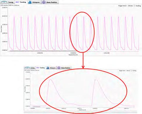
33 23
34 End of tutorial. 24

35 Measuring Real-time Integrated Energy using Host Commands This mode provides real-time pulse-to-pulse integrated energy readings through direct host commands. The hardware samples the PowerMax-Pro output at 40 MHz and begins integrating pulses upon an internal or external trigger signal. After each pulse is integrated the value is available in the host interface buffer. This feature enables high-speed measurement of high pulse energy modulated lasers (such as QCW fiber lasers) real-time within laser processing systems. An eleven-line com port utility is used to demonstrate the host command sequence in the following example. It shows what a typical host command sequence looks like using this mode. Lines shown in bold are the required command sets and required sequence to collect an energy measurement. Entering these commands out of sequence causes error codes. 25
36 Answer: CMD>SYST:*IDN? REPLY>OK SYSTEM INFORMATION CMD>CONF:PRI,FLAG,SEQ,PER REPLY>OK CMD>CONF:MEAS:SOUR:SEL FAST REPLY>OK CMD>CONF:MEAS:MOD J REPLY>OK CMD>TRIG:SOUR:INT REPLY>OK CMD>CONF:ZERO REPLY>OK CMD>TRIG:LEV MIN REPLY>OK CMD>CONF:MEAS:WIN REPLY>OK CMD>STAR REPLY>OK CMD>STOP The SCPI commands shown below give additional information on the commands used in the exercise just discussed. For a complete listing of user commands, refer to the Host Interface section of the PowerMax-Pro USB/RS User Manual ( ), available in Adobe PDF format on the installation CD sent with your system. SCMD>SYST:*IDN? The first command validates the connection settings. A standard *idn? queries the sensor for its identity. If the sensor does not return with a response, then the connection is not valid. 26
37 CMD>CONF:PRI,FLAG,SEQ,PER In this example the user samples the incoming period (rep rate) of the incoming pulses. This command lets you clearly read the energy level, sequence number, and rep rate in the sample. More information is available under Data Item Select in the Host Interface section of the PowerMax-Pro USB/RS User Manual. CMD>CONF:MEAS:SOUR:SEL FAST This command puts the PowerMax-Pro into a fast measurement (20 khz). Use this command before setting the meter to Joules mode and setting up the trigger. The PowerMax-Pro defaults to SLOW unless told to run in FAST mode. CMD>CONF:MEAS:MOD J This command prepares the sensor for an energy measurement. The Joules mode is set and default ranges based on the sensor are automatically applied. CMD>TRIG:SOUR:INT The Trigger source is now set to Internal and the Sensor tries to capture pulses based on a trigger level. Default trigger levels are applied. External triggering is also possible in this mode. For setup details, refer to the trigger parameters in the Host Interface section of the PowerMax-Pro USB/RS User Manual. CMD>CONF:ZERO Always zero the sensor before taking measurements. Make sure the laser is gated off when you configure Zero. Having any laser power causes a bias and, more importantly, this bias also determines the range of the energy permitted in the software. Low and high ranges are based on the sensor first and then on the bias applied during the zeroing operation. 27
38 CMD>TRIG:LEV MIN This command selects the value of the trigger level used in the measurement, based on the range found in an earlier step. The minimum range in this mode is essentially an autoset trigger level. The meter analyzes the baseline noise and sets a minimum trigger above the noise. When using Joules mode, try the MIN internal trigger setting before you try to enter absolute trigger percentages. The MIN internal trigger also makes the most efficient use of the pre-trigger (buffer). The trigger level can be set at minimum maximum in addition to percentage values. You can query the values of any given setting. For more information, reference the host commands in the Host Interface section of the PowerMax-Pro USB/RS User Manual. CMD>CONF:MEAS:WIN The configure measurement window sets the range where the PowerMax-Pro looks for and integrates a pulse. Always set a window that is just slightly longer than the laser pulse length, but not so long that the next pulse arrives before the window closes. If the window is set shorter than the laser pulse length, not all of the pulse will be captured and integrated. The algorithm integrates baseline noise if the window is set longer than the laser pulse length. This is likely to result in a low amount of error, so caution on the side of a slightly longer pulse length window than one that is too short. The value is in microseconds. In the above example, to set a measurement window of 20 milliseconds enter CONF:MEAS:WIN You can increase and decrease this value based on the application. CMD>STAR The Start command tells the system when to start collecting measurements. There are variations of commands for how many lines to collect and different times to use. For more information on SCPI, refer to the Host Interface section of the PowerMax-Pro USB/RS User Manual. CMD>STOP The Stop command discontinues the measurements. End of tutorial 28

39 Setting up the Cursor Feature This tutorial describes how to set up the Cursor feature within the LabMax-Pro PC software. The Cursor feature is a powerful tool for analyzing pulses that are captured in the LabMax-Pro software. You can use it after stopping live data collection or after importing a saved data file into the software. Procedure 1. [Graphics panel] Right-click in the Graphics panel to open the Trending Window Options menu. Trending Window Options menu Right-click in this general area to open the Trending Window Options menu. 29


40 2. Click the Show Selection Bounds Cursors checkbox in the drop-down menu. Cursors are dragged within the trend screen to fit around certain pulse shapes or features. Selection Bound cursors 30


41 Based on the region of the plot selected by the cursors, the Selection Bounds statistics automatically update. You can use the Time Axis - Width measurement to determine pulse width, rise-time, or fall-time of a pulse in the plot. The software also shades the area under the curve within the cursors and calculates the energy of a pulse or pulses within that region. The Energy Baseline setting can be used to determine if the pulse energy calculation is based on the 0 mw baseline level or the lower cursor level. 31

42 The Snap To Triggers setting can be used to set the cursors to the trigger point at the start of successive pulses. Then the Time Axis - Width measurement can be used to determine the period between pulses. Trigger points To reset the cursors to their original positions, make sure Snap To Triggers is not checked, then uncheck and recheck the Show Selection Bounds Cursors checkbox. This will reset the cursors in the Trend display. uncheck/recheck uncheck Original position of cursors End of tutorial 32
43
44 PowerMax -Pro PC Software Installation and Quick Start Guide Coherent Inc., 11/2015, printed in the USA Part No Rev. AA
User Guide. LabMax -Pro Mobile for ios
 User Guide LabMax -Pro Mobile for ios User Guide LabMax-Pro Mobile for ios 27650 SW 95th Ave. Wilsonville, OR 97070 LabMax-Pro Mobile for ios User Guide This document is copyrighted with all rights reserved.
User Manual. PowerMax -USB/RS. Sensor System
 User Manual PowerMax -USB/RS Sensor System User Manual PowerMax-USB/RS Sensor System 27650 SW 95th Ave. Wilsonville, OR 97070 PowerMax-USB/RS User Manual This document is copyrighted with all rights reserved.
MESURgauge Software. User s Guide
 MESURgauge Software User s Guide MESURgauge Software Thank you! Thank you for purchasing MESURgauge software, a data collection and analysis program developed to: Measure Collect data from digital force
MESURgauge Software. User s Guide
 MESURgauge Software User s Guide Thank you Thank you for purchasing MESURgauge software, a data collection and analysis program developed to: Measure Collect data from digital force gauges, torque gauges,
PowerMax-Pro kw Sensors
 PowerMax-Pro kw Sensors 1W to 3 kw PowerMax-Pro laser detectors have been enhanced to enable multi-kw continuous power measurement of laser beams. PowerMax-Pro detectors, first introduced in 2014, are
Component Tests User Manual
 Component Tests User Manual February 2009 EAZ0007E70C Rev. C Trademarks Acknowledgements Snap-on, Scanner, Fast-Track, and MODIS are trademarks of Snap-on Incorporated. All other marks are trademarks or
TROVIS-VIEW 4 Software TROVIS Operating Instructions EB 6661 EN. Electronics from SAMSON
 TROVIS-VIEW 4 Software TROVIS 6661 Operating Instructions Electronics from SAMSON EB 6661 EN Edition January 2015 Definition of signal words DANGER! Hazardous situations which, if not avoided, will result
Agilent 34826A BenchLink Data Logger for 34980A. Getting Started Guide. Agilent Technologies
 Agilent 34826A BenchLink Data Logger for 34980A Getting Started Guide Agilent Technologies Notices Agilent Technologies, Inc. 2006 No part of this manual may be reproduced in any form or by any means (including
User Manual Australia
 User Manual Australia April 2009 EAZ0057B06A Rev. A Trademarks Acknowledgements Snap-on, ShopStream Connect, ETHOS, MODIS, SOLUS, SOLUS PRO, and Vantage PRO are trademarks of Snap-on Incorporated. All
GXLink MultiChannel Wave Inserter Model SP-631
 800173-0A Digital High Speed GXLink MultiChannel Wave Inserter Model SP-631 User Manual Copyright 2009 It is prohibited to copy, reproduce or distribute this information in whole or in part without the
Deckblatt. APL Operator Guide SIMATIC PCS 7. Application description June Applikationen & Tools. Answers for industry.
 Deckblatt SIMATIC PCS 7 Application description June 2011 Applikationen & Tools Answers for industry. Industry Automation and Drive Technologies Service & Support Portal This article is taken from the
D A X A D D - I N AMPLICON DATA ACQUISITION EXCEL ADD-IN
 D A X A D D - I N AMPLICON DATA ACQUISITION EXCEL ADD-IN This Instruction Manual is supplied with the Data Acquisition Add-in to provide the user with sufficient information to utilise the purchased product
PowerMax-Pro USB and RS Sensors
 PowerMax-Pro USB and RS Sensors 200 mw to 150W PowerMax-Pro USB and RS sensors incorporate LabMax-Pro instrumentation directly within the sensor cable. Similar to other Coherent USB and RS sensors, this
GE Fanuc Automation. CIMPLICITY HMI Plant Edition. Trend and XY Chart. CIMPLICITY Monitoring and Control Products.
 GE Fanuc Automation CIMPLICITY Monitoring and Control Products CIMPLICITY HMI Plant Edition Trend and XY Chart Operation Manual GFK-1260H July 2001 Following is a list of documentation icons: GFL-005 Warning
Component Tests User Manual
 Component Tests User Manual February 2009 ZEEMS308G Rev. C Trademarks Acknowledgements Snap-on, Scanner, Fast-Track, and MODIS are trademarks of Snap-on Incorporated. All other marks are trademarks or
Spectrometer Visible Light Spectrometer V4.4
 Visible Light Spectrometer V4.4 Table of Contents Package Contents...3 Trademarks...4 Manual Driver and Application installation...5 Manual Application Installation...6 First Start of the Application...8
Agilent ChemStation Plus
 Agilent ChemStation Plus Getting Started Guide Agilent Technologies Notices Agilent Technologies, Inc. 2004, 2006-2008 No part of this manual may be reproduced in any form or by any means (including electronic
HikCentral Control Client. User Manual
 HikCentral Control Client User Manual Legal Information User Manual 2018 Hangzhou Hikvision Digital Technology Co., Ltd. About this Manual This Manual is subject to domestic and international copyright
TROVIS-VIEW 4 Software TROVIS Operating Instructions EB 6661 EN. Electronics from SAMSON
 TROVIS-VIEW 4 Software TROVIS 6661 Operating Instructions Electronics from SAMSON EB 6661 EN Edition August 2017 Definition of signal words DANGER! Hazardous situations which, if not avoided, will result
HawkEye 45T Display User Manual
 HawkEye 45T Display User Manual Rev 1.0.1, December 2006 EM-20889-1V101 Safety Guidelines This manual contains notices you have to observe in order to ensure your personal safety, as well as to prevent
User Manual. PowerMax-Pro USB/RS Sensor System
 User Manual TM PowerMax-Pro USB/RS Sensor System User Manual PowerMax-Pro USB/RS Sensor System 27650 SW 95th Ave. Wilsonville, OR 97070 PowerMax-Pro USB/RS User Manual This document is copyrighted with
Microscan Barcode Reader
 Microscan Barcode Reader Device Driver Guide For Research Use Only. Not for use in diagnostic procedures. Original Instructions Notices Agilent Technologies, Inc. 2017 No part of this manual may be reproduced
PICO LOGGING APPLICATION...
 1 Table of contents TABLE OF CONTENTS... 2 ABOUT THIS MANUAL... 3 IMPORTANT NOTES... 3 PICO LOGGING APPLICATION... 5 ABOUT THE PICO LOGGING PC APPLICATION... 5 WHERE TO GET A HOLD OF THE PICO LOGGING APPLICATION...
User Manual. LabMax -TOP Laser Power/Energy Meter
 User Manual LabMax -TOP Laser Power/Energy Meter User Manual LabMax-TOP Laser Power/Energy Meter 27650 SW 95th Ave. Wilsonville, OR 97070 LabMax-TOP User Manual This document is copyrighted with all rights
LabMax-Pro PC data collection
 LabMax-Pro PC data collection Table of Contents 1. The Question 2. Setting up data logging ahead of time 3. Exporting data after it s already been collected 4. Importing and exporting data from the LabMax-Pro
SIMATIC HMI. Configuring Graphics Displays. Product Brief. Edition 12/01. Table of Contents. Introduction. Commissioning Operating Units
 SIMATIC HMI Configuring Graphics Displays Table of Contents Introduction Commissioning Operating Units Product Brief Basic Steps for a Configuration Extend Configuration with Simple Elements Edition 12/01
Power and Energy Measurement Overview
 and Measurement Overview Compatibility Chart for Our Most Popular and LabMax-Pro LabMax-TOP and -TO FieldMate FieldMaxII-TOP and -TO & Standard Mode + High Speed Standard Mode Standard Mode Thermal SmartSensor
Operating Instructions
 Operating Instructions Before Using This Machine How to Use Converting into the Image Data Printer Driver Troubleshooting Read this manual carefully before you use this product and keep it handy for future
User Manual. LaserPAD PC. Multi-Channel Laser Power Analysis Display
 User Manual LaserPAD PC Multi-Channel Laser Power Analysis Display User Manual LaserPAD PC Multi-Channel Laser Power Analysis Display 27650 SW 95th Ave. Wilsonville, OR 97070 LaserPAD PC User Manual This
SequencePro Data Analysis Application. User Guide
 SequencePro Data Analysis Application User Guide SequencePro Data Analysis Application User Guide DRAFT October 31, 2001 12:52 pm, Title_page.fm Copyright 2001, Applied Biosystems. All rights reserved.
IMAGE STUDIO LITE. Tutorial Guide Featuring Image Studio Analysis Software Version 3.1
 IMAGE STUDIO LITE Tutorial Guide Featuring Image Studio Analysis Software Version 3.1 Notice The information contained in this document is subject to change without notice. LI-COR MAKES NO WARRANTY OF
Agilent ChemStation Plus
 Agilent ChemStation Plus Getting Started Guide Agilent Technologies Notices Agilent Technologies, Inc. 2004 No part of this manual may be reproduced in any form or by any means (including electronic storage
EOS-6000 Series Optical A/B Switch User Manual DC Version
 EOS-6000 Series Optical A/B Switch User Manual DC Version For more information on this and other products: Contact Sales at EMCORE 626-293-3400, or visit www.emcore.com. Table of Contents Table of Contents...2
WebPakCS Software Version 1.0
 WebPakCS Software Version 1.0 Instruction Manual D2-3447 The information in this manual is subject to change without notice. Throughout this manual, the following notes are used to alert you to safety
Lens Selection Software. User Manual
 Lens Selection Software User Manual Legal Information User Manual 2018 Hangzhou Hikvision Digital Technology Co., Ltd. About this Manual This Manual is subject to domestic and international copyright protection.
Agilent Technologies. Connectivity Guide. USB/LAN/GPIB Interfaces. Agilent Technologies
 Agilent Technologies USB/LAN/GPIB Interfaces Connectivity Guide Agilent Technologies Notices Agilent Technologies, Inc. 2003-2006 No part of this manual may be reproduced in any form or by any means (including
Opazity User Guide Setup, First Use & Advanced Technique
 Opazity User Guide Contents Introduction, T&C 1 Part 1. Installation and Setup 2 Part 2. Instructions for First Use 3 Part 3. Advanced technique: Highlighting areas of a slide at random 6 Appendix: End
Agilent Series Logic Analysis System
 Agilent 16900-Series Logic Analysis System Quick Start Guide for 16700-Series Users Agilent Technologies Notices Agilent Technologies, Inc. 2003-2004 No part of this manual may be reproduced in any form
Quick Start Guide Agilent Technologies 14565A Device Characterization Software for Windows 98, Windows NT 4.0, Windows 2000 and Windows XP
 Quick Start Guide Agilent Technologies 14565A Device Characterization Software for Windows 98, Windows NT 4.0, Windows 2000 and Windows XP sa Contents Description...3 System Requirements...3 Installing
PostScript3. Operating Instructions. PostScript 3 - Setting Up for Printing Printer Utility for Mac Appendix
 Operating Instructions PostScript3 2 3 PostScript 3 - Setting Up for Printing Printer Utility for Mac Appendix Read this manual carefully before you use this machine and keep it handy for future reference.
3M RFID Tracking Pad Model 770
 3M RFID Tracking Pad Model 770 Owners Manual 3M Information and Materials Security 3M Center, Building 225-4N-14 St. Paul, Minnesota 55144-1000 xx-xxxx-xxxx-x Rev 1 Copyright 2003 3M IPC. All rights reserved.
MODEL GE4138 DIGITAL CD/MP3/USB/SD ENCODING WITH PLL AM/FM ALARM CLOCK STEREO RADIO - USER MANUAL -
 MODEL GE4138 DIGITAL CD/MP3/USB/SD ENCODING WITH PLL AM/FM ALARM CLOCK STEREO RADIO - USER MANUAL - CAUTION RISK OF ELECTRIC SHOCK DO NOT OPEN CAUTION: TO REDUCE THE RISK OF ELECTRIC SHOCK, DO NOT REMOVE
Logger Pro 3. Quick Reference
 Logger Pro 3 Quick Reference Getting Started Logger Pro Requirements To use Logger Pro, you must have the following equipment: Windows 98, 2000, ME, NT, or XP on a Pentium processor or equivalent, 133
C CURE HDVR Integration User Guide. Version 1.93 REVISION A0
 C CURE 9000 Version 1.93 HDVR Integration User Guide REVISION A0 6 Technology Park Drive Westford, MA 01886-3140 http://www.swhouse.com Fax: 978-577-4392 Phone: 978-577-4000 Copyright and Trademarks C
Thermal Transient Test Installation and Operating Manual
 Thermal Transient Test Installation and Operating Manual 2705A De La Vina Street Santa Barbara, California 93105 Telephone (805) 682-0900 descon@silcom.com www. santabarbaraautomation.com Installation
3. Software Operation
 3. Software Operation Limitation of Liability Michigan Instruments, Inc. warrants that the PneuView software will conform to the published specifications and documentation, provided that it is used on
Upgrading BMDM and BMRG Software and MPM, BDS and DCM Firmware
 Upgrading BMDM and BMRG Software and MPM, BDS and DCM Firmware 990 South Rogers Circle, Suite 11 Boca Raton, FL 33487 Tel: 561-997-2299 Fax: 561-997-5588 www.alber.com 1. Warranty and Limitation of Liability
DriveWizard Plus Instruction Manual
 DriveWizard Plus Instruction Manual To properly use the product, read this manual thoroughly. MANUAL NO. TOEP C730600 20C Table of Contents Safety Symbols and Markings...4 Manual Overview...5 Related Manuals...5
Meterless Laser Power/Energy Measurement Simplifies Embedding
 White Paper Meterless Laser Power/Energy Measurement Simplifies Embedding Traditional laser power and energy measurement instruments typically comprise a sensor head connected to separate meter electronics.
User Guide 701P Wide Format Solution Wide Format Scan Service
 User Guide 701P44865 6204 Wide Format Solution Wide Format Scan Service Xerox Corporation Global Knowledge & Language Services 800 Phillips Road Bldg. 845-17S Webster, NY 14580 Copyright 2006 Xerox Corporation.
Roland CutChoice. Ver. 1 USER S MANUAL
 Roland CutChoice Ver. 1 USER S MANUAL Thank you very much for purchasing the Roland cutter. To ensure correct and safe usage with a full understanding of this product s performance, please be sure to read
User Guide. Model Temperature Datalogger Kit Model Temperature and Humidity Datalogger Kit Model SW276 Datalogging Software SW276
 User Guide Model 42265 Temperature Datalogger Kit Model 42275 Temperature and Humidity Datalogger Kit Model SW276 Datalogging Software SW276 Introduction Congratulations on your purchase of Extech Instrument
TDSPTD Protocol Trigger and Decode Application Online Help
 xx ZZZ TDSPTD Protocol Trigger and Decode Application Online Help *P077002502* 077-0025-02 ZZZ TDSPTD Protocol Trigger and Decode Application Online Help www.tektronix.com 077-0025-02 Copyright Tektronix.
General Information 1. Connection 2. User Interface 3 ATC5300. Menus 4. Automatic Transfer Controller. Remote Control Software Manual A5E
 s General Information 1 Connection 2 Automatic Transfer Controller User Interface 3 Menus 4 Remote Control Software Manual Edition 01/2010 A5E02469028-01 Legal information Warning notice system This manual
41126 Cognento (MODENA) Italy Via Bottego 33/A Tel: +39-(0) Internet: Fax: +39-(0)
 Italy Via Bottego 33/A Tel: +39-(0) Internet: Fax: +39-(0)") QUICK ANALYZER User Guide Version 5.3 Index 1.0 Generality... 2 LICENSE AGREEMENT... 3 2.0 Channels Configuration... 4 2.1 IdroScan Data Log Management... 6 3.0 Test Results... 9 4.0 Excel Export... 10
QUICK ANALYZER User Guide Version 5.3 Index 1.0 Generality... 2 LICENSE AGREEMENT... 3 2.0 Channels Configuration... 4 2.1 IdroScan Data Log Management... 6 3.0 Test Results... 9 4.0 Excel Export... 10
Master Oscillator Power Amplifier SLD System MOPA-SLD-850
 Master Oscillator Power Amplifier SLD System MOPA-SLD-850 1. Product Description The Superlum MOPA-SLD-850 is an ultra-high power SLD-based light source that features an extremely weak sensitivity to optical
A variety of ECONseries modules provide economical yet flexible solutions. Waveform Generation
 ECONseries BUS: USB Type: Economy, Mini-Instruments ECONseries Economy USB Mini-Instruments Flexible Yet Economical A variety of low-cost ECONseries modules are available to provide flexible yet economical
MotionView Configuration and Programming Software USER S MANUAL
 MotionView Configuration and Programming Software USER S MANUAL IM94MV01C Table of Contents 1 MotionView Software Overview......................................... 3 1.1 Installation and Package Revision.................................................
About this Guide How the Document is Organized... 5 Definition of Terms Chapter 1 PMManager and Devices... 6
 Table of Contents About this Guide... 5 How the Document is Organized... 5 Definition of Terms... 5 Chapter 1 PMManager and Devices... 6 PMManager Features... 6 Package Contents... 6 System Requirements...
Smart Monitor ZG2 User s Manual
 Smart Monitor ZG2 User s Manual Smart Sensors ZG2 Series 2D Profile Measuring Sensors CONTENTS SMART MONITOR ZG2 USER S MANUAL...1 SECTION 1 PREPARATIONS...2 Installing the Smart Monitor ZG2 on a Computer...
NuFlo TM. SCM Viewer TM. User Manual. Manual No , Rev. A
 NuFlo TM SCM Viewer TM User Manual Manual No. 30165020, Rev. A Revision History The following table shows the revision history for this document: Date Description Approved by 2-6-2006 Initial release of
NCH Software TwelveKeys Music Transcription Software
 NCH Software TwelveKeys Music Transcription Software This user guide has been created for use with TwelveKeys Music Transcription Software Version 1.xx NCH Software Technical Support If you have difficulties
Manual Version: V1.00. Video Decoder User Manual
 Manual Version: V1.00 Video Decoder User Manual Thank you for purchasing our product. If there are any questions, or requests, please do not hesitate to contact the dealer. Copyright Copyright 2016 Zhejiang
VANGUARD LOAD TAP CHANGER ANALYZER (LTCA) VERSION 2.xx SOFTWARE MANUAL. LTCA-10, LTCA-40, WRM-10P, WRM-40, TRM-20, TRM-40, TRM-203, and TRM-403
 VERSION 2.xx SOFTWARE MANUAL. LTCA-10, LTCA-40, WRM-10P, WRM-40, TRM-20, TRM-40, TRM-203, and TRM-403") VANGUARD LOAD TAP CHANGER ANALYZER (LTCA) VERSION 2.xx SOFTWARE MANUAL For Use with Vanguard s LTCA-10, LTCA-40, WRM-10P, WRM-40, TRM-20, TRM-40, TRM-203, and TRM-403 Load Tap Changer Analyzers and Winding
VANGUARD LOAD TAP CHANGER ANALYZER (LTCA) VERSION 2.xx SOFTWARE MANUAL For Use with Vanguard s LTCA-10, LTCA-40, WRM-10P, WRM-40, TRM-20, TRM-40, TRM-203, and TRM-403 Load Tap Changer Analyzers and Winding
Portable CD/MP3 Stereo
 Portable CD/MP3 Stereo User Guide Now you have purchased a Tevion product you can rest assured in the knowledge that as well as your 3 year parts and labour warranty you have the added peace of mind of
Cal-Bay Systems XY Plotter, Time-Base Recorder, Automated Tester. Users Guide. Rev 3.1
 Cal-Bay Systems XY Plotter, Time-Base Recorder, Automated Tester Users Guide Rev 3.1 Contents... 1 Quick Start Guide... 2 Selecting a Test Specification... 3 Clearing Traces... 4 Saving Traces...4 Loading
Startup Software Quick Start Guide
 Startup Software Quick Start Guide Safety precautions Observe the following safety precautions before using this product and any associated instrumentation. Although some instruments and accessories would
User Guide. PlexBright 4 Channel Optogenetic Controller with Radiant Software. Part of the PlexBright Optogenetic Stimulation System
 User Guide Radiant Version 2, November 2016 PlexBright 4 Channel Optogenetic Controller with Radiant Software Part of the PlexBright Optogenetic Stimulation System Plexon Inc 6500 Greenville Avenue, Suite
CiM-25. Quick Start Guide. IP-Enabled M&C Part Number CD/CIM25QSG.IOM Rev. 0
 CiM-25 Quick Start Guide IP-Enabled M&C Part Number Rev. 0 CiM-25 Quick Start Guide Comtech EF Data is an ISO 9001 Registered Company. IP Enabled M&C Part Number REV. 0 March 3, 2004 Copyright Comtech
FIREPOWER M04 RGB MMO LASER MOUSE INSTRUCTION MANUAL ADXLM0418
 FIREPOWER M04 RGB MMO LASER MOUSE INSTRUCTION MANUAL ADXLM0418 Contents Safety Warnings... 4 Unpacking... 5 Product Overview... 6 Adjusting the Weight... 7 System Requirements... 8 Software Installation...
Student Quick Reference Guide
 Student Quick Reference Guide How to use this guide The Chart Student Quick Reference Guide is a resource for PowerLab systems in the classroom laboratory. The topics in this guide are arranged to help
User's Guide. Model RPM10 Laser Photo / Contact Tachometer with IR Thermometer
 User's Guide Model RPM10 Laser Photo / Contact Tachometer with IR Thermometer Introduction Congratulations on your purchase of Extech's Laser Photo/Contact Tachometer with Non-Contact IR Thermometer, Model
MindSphere. Fleet Manager. Introduction to "Fleet Manager" 1. User interface for "Fleet Manager" 2. User rights in "Fleet Manager" 3.
 Introduction to "Fleet Manager" 1 User interface for "Fleet Manager" 2 MindSphere User rights in "Fleet Manager" 3 Asset navigation 4 Using extensions 5 System Manual V1801.K0507 V1801.K0214 Legal information
Chapter 1 Introducing the OM-USB-1608FS-Plus... 6 Functional block diagram... 6
 Table of Contents Preface About this User's Guide... 5 What you will learn from this user's guide... 5 Conventions in this user's guide... 5 Where to find more information... 5 Chapter 1 Introducing the
VIBbox 64-Channel Sound & Vibration Solution
 VIBbox 64-Channel Sound & Vibration Solution VIBbox is a high-accuracy, high channel count, dynamic signal analyzer system for sound and vibration applications. VIBbox packages four DT9857E modules in
Operator Manual. MS1000 Software. Trencher Monitoring System
 Operator Manual MS1000 Software Trencher Monitoring System MS1000 Software Trencher Monitoring System Operator Manual Release 1.2 This manual provides you with the basic information required to operate
CS3000 MMI SW-Version 6.1 Control and Configuration Software for FlexPak3000 V , GV3000 V and Liqui-Flo. Instruction Manual
 CS3000 MMI SW-Version 6.1 Control and Configuration Software for FlexPak3000 V2.0-4.3, GV3000 V2.0-6.0 and Liqui-Flo Instruction Manual Manual P/N: 899.05.84 Firmware P/N: 788.05.30 User Manual: 49 1307e
Wavy for PAX Ver. 4.0
 Operation Manual Sequence Creation Software Wavy for PAX Ver. 4.0 SPEC70289 Version 4.0 Prepared: June 21, 2006 KIKUSUI ELECTRONICS CORPORATION 1/34 Contents Note Before contacting us to request repair,
User s Manual. AQ6150/AQ6151 Optical Wavelength Meter IM AQ EN. 1st Edition
 User s Manual AQ6150/AQ6151 Optical Wavelength Meter 1st Edition Notes Trademarks Revisions Thank you for purchasing the AQ6150/AQ6151 Optical Wavelength Meter. The AQ6150/ AQ6151 is a high-speed wavelength
Configuration Guide for Microsoft Internet Connection Sharing
 Configuration Guide for Microsoft Internet Connection Sharing HUB INTERNET HOST CLIENTS Copyright 2002 Hughes Network Systems, Inc., a wholly owned subsidiary of Hughes Electronics Corporation. All rights
VIBBOX. 32, 48, or 64-Channel Sound & Vibration Solution Expansion to 256 Channels. Key Feature of Each VIBbox: Table 1. Key Features of VIBbox Models
 VIBBOX 32, 48, or 64-Channel Sound & Vibration Solution Expansion to 256 Channels VIBbox is a high-accuracy, high channel count, dynamic signal analyzer system for sound and vibration applications. Each
CORD-XL Dual-Channel Electronic Chart Recorder User s Manual
 CORD-XL Dual-Channel Electronic Chart Recorder User s Manual Rohrback Cosasco Systems Inc. 11841 E. Smith Ave Santa Fe Springs, CA 90670 Tel: (562) 949-0123 Fax: (562) 949-3065 P/N 720701-Manual Rev E
Toast Audio Assistant User Guide
 Toast Audio Assistant User Guide Toast Audio Assistant lets you capture audio from a variety of sources. You can then edit the audio, break it up into tracks, add effects, and export it to itunes or burn
HikCentral Control Client. User Manual
 HikCentral Control Client User Manual Legal Information User Manual 2018 Hangzhou Hikvision Digital Technology Co., Ltd. About this Manual This Manual is subject to domestic and international copyright
Wavy for PLZ-4W Ver. 4.0
 Operation Manual Sequence Creation Software Wavy for PLZ-4W Ver. 4.0 Version 4.0 Prepared: June 21, 2006 KIKUSUI ELECTRONICS CORPORATION 1/35 Note Before contacting us to request repair, inspection, or
vippaq Main App. User Guide
 vippaq Main App. User Guide Edition 1d July 2008 Contents 1 INTRODUCTION 3 1.1 3 2 SYSTEM PREPARATION 4 2.1.1 Measuring Head Connection 5 2.1.2 Position the Measuring Heads 5 2.1.3 Start Job 5 3 MEASURE
Desktop Studio: Charts. Version: 7.3
 Desktop Studio: Charts Version: 7.3 Copyright 2015 Intellicus Technologies This document and its content is copyrighted material of Intellicus Technologies. The content may not be copied or derived from,
Nano Laptop Laser Mouse
 Nano Laptop Laser Mouse RF-NANMSE User Guide Rocketfish RF-NANMSE Nano Laptop Laser Mouse Contents Introduction... 3 Features... 3 Using the mouse...12 Maintaining...20 Troubleshooting...20 Specifications...21
Wavy for PAS&PWR Ver. 5.0
 Kikuchi 07 22 08 Operation Manual Sequence Creation Software Kobayashi 07 22 08 Wavy for PAS&PWR Ver. 5.0 Version 5.0 Prepared: July 22, 2008 KIKUSUI ELECTRONICS CORPORATION IB01809 1 1/34 Note Before
Komodo CAN Interface. Komodo TM CAN Interface GUI. Komodo GUI User s Manual v1.50 Octorber 26, 2012
 Komodo CAN Interface Komodo GUI User s Manual v1.50 Octorber 26, 2012 Summary The Komodo GUI is a graphical application for use with the Komodo CAN Interface. The application provides access to CAN Bus
Agilent E4418/19A Power Meter Hardware Upgrade Kit
 Agilent E4418/19A Power Meter Hardware Upgrade Kit (E9300 Compatible) Installation Guide Agilent Technologies Notices Agilent Technologies, Inc. 2009 No part of this manual may be reproduced in any form
HDMI MATRIX SWITCHER B-120-HDMATRIX-4x4/8x8 CONFIGURATION UTILITY MANUAL
 HDMI MATRIX SWITCHER B-120-HDMATRIX-4x4/8x8 CONFIGURATION UTILITY MANUAL IMPORTANT SAFETY INSTRUCTIONS To reduce the risk of fire or electric shock, read and follow all instructions and warnings in this
Engineering Tool for PC SDWP001 Operating Manual
 Inverter HF-520/HF-X20 Series SF-520 Series Engineering Tool for PC SDWP001 Operating Manual 1 Manual No. DM2308E-1 Table of Contents Safety Symbols and Markings...4 Safety Notes and Instructions...4 Manual
E3xA, E3xB, E3xC, E3xE
 ZL0140-0C Page 1 of 21 2017 Veris Industries USA 800.354.8556 or +1.503.598.4564 / support@veris.com 0717 Commissioning Guide Power Monitoring E34E E31 * E30E & E31E E34A E30 *The CE mark indicates RoHS2
Quick Start Guide for Administrators and Operators Cyber Advanced Warning System
 NSS Labs Quick Start Guide for Administrators and Operators Cyber Advanced Warning System Introduction to the Cyber Advanced Warning System and RiskViewer... 1 Activating Your Account... 2 Adding a New
FlukeView Forms. Users Manual. Documenting Software
 FlukeView Forms Documenting Software September 2000, Rev. 6, 2/09 2002, 2003, 2005, 2007, 2009 Fluke Corporation. All rights reserved. All product names are trademarks of their respective companies. Table
CyberComm Pro Data Acquisition Software Installation & User Guide
 CyberComm Pro 2.2.3 Data Acquisition Software Installation & User Guide ph 1100 and ph 2100 Bench ph and Bench ph/ion Meter Technology Made Easy... 68X090822 rev 1 Aug 2002 2 PREFACE Thank you for selecting
User's Guide. Model RPM10 Laser Photo / Contact Tachometer with IR Thermometer. Patented
 User's Guide 99 Washington Street Melrose, MA 02176 Fax 781-665-0780 TestEquipmentDepot.com Model RPM10 Laser Photo / Contact Tachometer with IR Thermometer Patented Introduction Congratulations on your
User Manual (Vers. 1.03)
") PLUSSoftUsb Power Meter Mode User Manual (Vers. 1.03) Laserpoint srl - Via Burona, 51-20090 Vimodrone (Milano) - Italy Phone +39 02 27 400 236 - Telefax +39 02 25 029 161 www.laserpoint.it 1 Contents CONTENTS
PLUSSoftUsb Power Meter Mode User Manual (Vers. 1.03) Laserpoint srl - Via Burona, 51-20090 Vimodrone (Milano) - Italy Phone +39 02 27 400 236 - Telefax +39 02 25 029 161 www.laserpoint.it 1 Contents CONTENTS
MindSphere. Fleet Manager. Introduction to "Fleet Manager" 1. User interface for "Fleet Manager" 2. User rights in "Fleet Manager" 3
 Introduction to "Fleet Manager" 1 User interface for "Fleet Manager" 2 MindSphere User rights in "" 3 Asset navigation 4 Using extensions 5 System Manual 08/2018 V1801.K0730 Legal information Warning notice