Software Setup Instructions for the Foster Control System used in the Explora Dome Observatories
|
|
|
- Lora Cole
- 5 years ago
- Views:
Transcription


1 Software Setup Instructions for the Foster Control System used in the Explora Dome Observatories
2 Contents Pages 3 & 4 The new tic counter system & home position sensor Page 5 Control Boxes Pages 6-8 Down Loading procedure of the ASCOM program Page 9 Unzipping the Zipped Dome Set up Folder Pages 10 & 11 Installing the AstroMc program Page 12 Setting the AstroMc Program to run as Administrator Page Basic set up of the Dome Rotation Page Shutter Doors Setup Page Updating Firmware in the Control Boxes Page 27 Various errors if you don t install ASCOM first. Page Connecting the Control Boxes to the Dome Hardware Page Setting Up the Telescope in the AstroMC Program


3 This is the New Style Tic Counter and Home Sensor Home Sensor & Mount Home Sensor Mounted


4 This is the New Style Charging System with the Home Sensor mounted to it.


 (Note the newer rotation and shutter boards now use a USB connection.")
5 The shape and size of these boxes change from time to time. Here is a list of steps that have been put together to help you understand what you need to do and the order they need to be done in. In order for you to have the best results during basic set up of the software and hardware. We try to set up the control boxes with the latest Firmware, you will know if this has been done to your control box by the label with what firmware is loaded on the board in the control and a software version number on a label on the box itself. If there is a label telling you the information on the box you can ship through the general setup info. But keep it handy so you can update the firmware when needed. (Always keep the firmware and software versions grouped together in the package down loaded) (Note the newer rotation and shutter boards now use a USB connection.) The Older Foster System do use a Serial to USB cable and supplies a cable that has a proven driver that works with it, BUT if you have a Serial port on your Desk Top Computer it is always best to use that rather then the USB adaptor. There is a program called Snap Shot that is included with Windows 10, it is used to take a snap shot of an area of the screen if you run into a problem during the set up as seen in the instructions. Then forward it to stanralph@fostersystems.com or Dan@PolyDome.com and we will find the answer needed to solve the problem and return an answer as soon as we can. Then we will add the issue to the instructions so there can be answers for others who may run into the same problem in the future.
.")
 This will start the down load, you should be able to save as and put it where you want (Desk Top is my preference just to find it easer) Than go to the Ascom web site")
6 Down Loading Needed Software & Firmware You may have trouble down loading the Dome Update file using the Explore program we have found that the Firefox Program work best to use. The first thing you want to do is go to the Foster Systems website ( Than go to the Download Center click on software (Picture 1) than scroll down to Dome Update and click Dome Update. (Picture2) This will start the down load, you should be able to save as and put it where you want (Desk Top is my preference just to find it easer) Than go to the Ascom web site and down load the Ascom Platform again (save as) option and save it to where you want.(picture 3) Picture 1 Picture 2 Picture 3

 click on the run button.")
 click the")
7 Installing Ascom Software Now the first program you want to install is the ASCOM program this needs to be installed before you install the Dome Install Software. (Picture 9) Double click the ASCOM Platform icon. This will open the Open File Security Warning box (Picture 10) click on the run button. The Install Aware Wizard will appear and show progress of install bar. (Picture 11). Once completed the ASCOM Platform6 SP1 Install ware Wizard will appear (Picture 12) click the Install button at the bottom of the window. Picture 9 Picture 10 Picture 11 Picture 12
.")


 just move them to where you want them on the desktop.")
8 Now you will see the progress bar (Picture 14) when it reaches the end it will look like (Picture 15). If you do not uncheck the Display the Ascom Platform 6 SP1 box it will automatically open the pdf file when you push the Finish button. (Picture 16). Once you close the pdf file you should see the 3 different Ascom icons on the desktop. (Picture 17) just move them to where you want them on the desktop. This program just runs in the back ground when you are using the AstroMc program and your telescope program. Picture 14 Picture 15 Picture 16 Picture 17


9 Unzipping the AstroMC Program Make sure all Anti Vires Programs are turned off Now we move on to the Dome Install Folder. (Picture 1) Select the Dome Install zipped folder and double click on it. This will open another Dome Install folder. (Picture 2) Double click on the Dome Install folder. In side the Dome Install folder there are a number of folders. (Picture 3) Double click on Dome Setup This opens the language box if English is your choice click Ok (Picture 4) (The CPS USB Drivers are only used in special installs) Picture 1 Picture 2 Picture 3 Picture 4
 Click on")


 That bring you to the Install screen just click Next.")
10 Installing the AstroMc Program Now you should be in the Welcome to the AstroMC Setup box (Picture 1) Click on the Next button. It brings you to the License Agreement check the I accept the agreement box and click Next (Picture 2) That brings you to the Information screen read it and if all Foster Programs are closed click Next (Picture 3) That bring you to the Install screen just click Next. (Picture 4) Picture 1 Picture 3 Picture 2 Picture 4

 for this first installation.")
 This should bring up the Registration Window.")

11 When the install process is done (Picture 9) This brings you to the Information window read this before proceeding, than click on the Next button (Picture 10) This opens the Finish window. Uncheck the (Launch AstroMC) for this first installation. Click Finish for completion. (Picture 11) This should bring up the Registration Window. (Picture 12) By registering you software you will be kept up to date when software & firmware changes have been made along with warranty information. Once this is done The AstroMc program icon will appear on the Desk top. The software is now installed. Picture 9 Picture 10 Picture 11 Picture 12


 that opens the AstroMc Properties")
 once done")

12 Setting the AstroMc Program to run as Administrator The first thing you want to do is set the AstroMc program to run as administrator, start by right clicking the AstroMc Icon on the desk top, (Picture 1) that will open a window and at the bottom of the window click on the Properties button, (Picture 2) that opens the AstroMc Properties box, under Compatibility tab click, Run this program as administrator, (Picture3) once done close the windows. Now you are ready to start the AstroMC program, double click the AstroMC Icon. Picture 1 Picture 2 Picture 3

 If you did not register your software during set up then the first time you open the program the Register your product window will open, (Picture 2) enter your name and email then click")
 If there has been a change and you have registered your program you will see a notice displayed on the program window telling you there is a newer version available.")
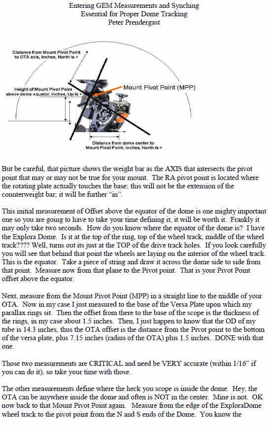
13 Set Up of the Basic AstroMc Rotation Program You are now ready to plug in your Rotation Control box. Once you plug the USB cord in, the computer should recognize it and give you a found new hardware and it is working properly notice. Now power up the control box. After that is complete, double-click on the AstroMc icon on the Desktop. (Picture 1) If you did not register your software during set up then the first time you open the program the Register your product window will open, (Picture 2) enter your name and then click OK. (This registration helps keep you informed when changes have been made to the software or firmware and service help.) After a short time, the main Dome Control Panel will be displayed. (Picture 3) If there has been a change and you have registered your program you will see a notice displayed on the program window telling you there is a newer version available. (Picture 4) Click on the bar for more information and to down load the Up Date package. Updating the software/firmware is reasonably simple (See Appendix 2) It is important to keep reasonably current since Foster Systems always improves addresses an issue using the current release. Your installation package may be Release while the update may be Release Keeping current is a good idea, but it is also a good idea to archive the previous update package so that you can fall back in case there s a problem with an update. Picture 1 Picture 3 Picture 2 Picture 4
 a box will appear on the screen this box will most likely be blank (Picture 2) Now click")


14 Running the AstroMc Rotation Program Click on the Tool drop down menu, under Tool select Traffic (Picture 1) a box will appear on the screen this box will most likely be blank (Picture 2) Now click on ObsClt Menu and select Setup (Picture 3) a new window will open called Setup (Picture 4) set your comport, if there are several you may need to go through them until you see traffic movement in the Traffic window (Picture 5) The Comms OK light will turn green if the connection is correct. if you are connected to the internet the Net Ok will be green also. Picture 2 Picture 1 Picture 4 Picture 3 Picture 5
15 Before going any further, you need to make sure that your Tick Counter Led light flashes each time it pass a hole in the Tic Disk. This function is very important since counting ticks is the way the software tell the Dome how far to move. Test this by using the hand paddle supplied with the System. Just plug it into the RJ connector on the right side on the front of the board. You need the control box open to do this. Also have the home sensor mounted to the Mounting ring in a location that allows the magnet mounted to the drive track to past back and forth past the sensor as often as possible during normal operations, The reason is every time the magnet passes the sensor it relines the Dome tracking position. Now shut down the AstroMc program and restart it, the reason for this step is because every time you use the hand paddle you disconnect the program form the control box and the only way to reconnect it is to restart the program. (Keep this in mind as you work with the program and the hand paddle.) The next step is to check and make sure the Dome is rotating the right direction, under the ObsCtl menu click on the Wiring/ Speed Setup (Picture 1) and the window will open up (Picture 2) click on Direction Test, it will say moving East and another window will open, (Picture 4) read it and do what is needed to correct it. Picture 1 Picture 4 Picture 2 Picture 3
 This will open a window called Setup, go to the AZ Auto Cal. Button and click it.")
16 Now you want to do an Auto Cal of the Dome before you do any other steps. Click on the ObsClt menu and select Wiring/Motor Control label (Picture 1) This will open a window called Setup, go to the AZ Auto Cal. Button and click it. (picture 2) The button will turn Green (Picture 3) The dome will rotate to the Home Position and stop then it will make one full rotation and stop at the Home Position again. The software will display the number of ticks upon completion. (Picture 4) Calibration is complete and the dome is ready for next setup operation. Picture 1 Picture 2 Picture 3 Picture 4

 and select Reverse under Rotation section. (Picture 2) then click Set New Parameters for these changes to take affect.")
 the button should turn Green and the dot to the left Red.")
17 Now you should be able to slew your Dome East and West by clicking the buttons on the Control Panel. A word of definition: Slew East means that the Dome moves counter clockwise. Slew West is clockwise in motion If these directions are not correct on your first start up then you need to go to the ObsCtl drop down menu and select Wiring/Motor window (Picture 1) and select Reverse under Rotation section. (Picture 2) then click Set New Parameters for these changes to take affect. Similar options are available to reverse Shutter switches and shutter motor directions if required. With the tick counter & Home Sensor working properly, click the Slew East button (Picture 3) the button should turn Green and the dot to the left Red. If slewing East click on the button to stop the slew. Now click on the Slew West button (Picture 4) the button should also turn Green and the Dot to the right should be Red now also. Now click the Slew West button to stop the Dome rotation. Picture 1 Picture 3 Picture 2 Picture 4


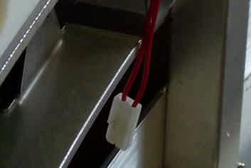
18 Setting up the Shutter Control Box Operation The Shutter control box works on a wireless connection to the Rotation control box, so that needs to be set up and working properly before the Automatic Shutter controls will work with the control panel in the AstroMc program. The Shutter control box can be operated manually with the hand paddle also. This works on a basic program into the shutter control box from the factory. It works well this way for testing the motors and limit switches during set up and can be used to override the computer control during operations if needed. It has a delay from the time you push the toggle switch until the motor in engaged so count to 30 before you try the switch in the other direction when you first try it. The hand paddle works one way at a time. It will only work with the doors starting in the closed position. This means when you start the open cycle you need to go all the way through until both doors are in the open position. You can stop during the cycle and restart but you can not back up a door. During testing you trigger the limit switch by hand to simulate operations and check to see that the open and close limit switch are working properly. When you first engage the upper shutter motor it starts out at full speed but after a few seconds it will slow down. This is programmed this way because of the limit switch set up on the older Domes and can not be changed for now. If you purchased the system to install on your own the first thing you should do is test the system before you install it. This will also tell you if the motors are working in the right direction and the wright order. If they are not then check to make sure they are plugged into the wright connection on the control box. If they are and the motors are truing the wrong way the easiest way to fix this problem is to open the control box and revers the red and black wires on that motor plug. (Picture 1&2) This can also be done through the AstroMc program but is of little use during this test period. But when you open the program for the first time and the motors are running in the wrong direction then it is the way to reverse them. Picture 1 Picture 2
 and you are going to operate the shutter doors from the AstroMc program.")
19 Now if you have all the limit switches mounted and in working order, the shutter motors installed and working properly, the rotation control box is plugged in and working properly, and you have the Shutter control box plugged in and powered up, (the little green light flashes on both control boxes) and you are going to operate the shutter doors from the AstroMc program. (You should have the Automatic Shutter box in the Set Up field check already but if the Open Shutter button is not showing look to see that it is checked.) When you first open the AstroMc program the Shutter Link OK is red (Picture3) but in a few seconds it will turn green if everything is working, (it can takes up to 30 seconds). (Picture 4) The (Open Shutter) button will be gray in color the (Upper & Lower) buttons to the right of the Open Shutter Button will be gray also. (Picture 5) When you click on the (Open Shutter) button to open the shutter doors it will turn light gray (Picture 6) the upper & lower buttons will stay gray until the first limit switch is trigger wile the upper doors is opening and it will turn green. (Picture 7) When both doors are open they both will turn Green (Picture 8) Picture 3 Picture 4 Picture 5 Picture 6 Picture 7 Picture 8

 and the upper button will turn from green to gray when it reaches")

 If every thing is working you are ready to move to the next setup stage.")
20 When you Close the Shutter Doors The Close Shutter button will turn light gray and say Shutter Open in green. (Picture 9) The Lower button will turn from green to gray when it is triggered by the door reaching the closed position, (Picture 10) and the upper button will turn from green to gray when it reaches the closed position. (Picture 10). When the both door are closed the Upper button will turn Gray, and it will say Shutters Closed in Green and the shutter button will say Open Shutter. (Picture 11) If every thing is working you are ready to move to the next setup stage. Remember you can watch the limit switches by opening the ObsCtl drop down menu and clicking on wiring/motor check link. Here you can change different aspects of the setup also. Bottom of this page. Picture 9 Picture 11 Picture 10

 and double click on it.")

 highlight the folder Mcloader and double click it to open")
21 Updating Firmware in the Control Boxes Photos on this page show the dialog boxes you would see when you install the MCloader program. Start in the folder Dome Install highlight the folder Firmware (Picture B1) and double click on it. This will open the Firmware folder, highlight the folder Firmware Updater and double click on it. (Picture B2) This will open a folder (Firmware Updater), (Picture B3) highlight the folder Mcloader and double click it to open another folder Firmware. (Picture B4) Picture B1 Picture B2 Picture B3 Picture B4
 This will open")

 click the Next button at the bottom, this")

22 Now with the Mcloader folder opened highlight and double click on the MCloader icon (Picture B5) This will open the Compressed (Zipped) Folder Warning box, click on the extract all button. (Picture B6) This brings up the Extraction Wizard folder (Picture B7) click the Next button at the bottom, this will open the next window as to where you want to put the file chose where then click the next button. (Picture B8) Picture B5 Picture B7 Picture B6 Picture B8
 This brings you to a")
 This will open the folder")
 Now drag the program icon")
 Picture B9 Picture B10")
23 Now click on the Finish button at the bottom (Picture 9) This brings you to a new folder with the Mcloader folder in it. (Picture B10) This will open the folder Mcloader where the program icon is located (Picture 11) Now drag the program icon onto your desktop and close the folder. (Picture 12) Picture B9 Picture B10 Picture B11 Picture B12
 Select the (AstroMC DR A6.")
 opens (Picture B15) you will want close it and then")
 click on the down arrow of the com box and then select the correct COM")

24 With the MC Loader icon on the desk top double click on it to open the program and then go to the open folder in the top left corner (Picture B13) Select the (AstroMC DR A6. HEX) file and then click the Open button in the lower right corner (Picture B14) Now if the Warning box (Reset Required) opens (Picture B15) you will want close it and then check the Com button located in the lower half of the data area of the window. (Picture B16) click on the down arrow of the com box and then select the correct COM for the cable connecting the computer to the control box if there are several it is just a guessing game until you find the right com port. Picture B13 Picture B14 Picture B15 Picture B16
25 Now click the Program button on the menu bar. (Picture B17) and the Loader Status window will open and show a progress bar until it is loaded, (Picture B18) when the progress bar closes the window will say Ready in the lower left corner. (Picture B19) If you want you can click on the Verify button (Picture B20) to check the programing. Once this box is done you can close the program or if you have the shutter control box you will want to check the programing in that box as well. Picture B17 Picture B19 Picture B18 Picture B20
 file and then click the Open button in the lower right corner (Picture B21) Now if the Warning box (Reset Required) opens (Picture B15) you will want to close it and then check the Com button")
26 With the MC Loader open go to the Open folder in the top left corner (Picture B21) Select the (AstroMC DS A9. HEX) file and then click the Open button in the lower right corner (Picture B21) Now if the Warning box (Reset Required) opens (Picture B15) you will want to close it and then check the Com button located in the lower half of the data area of the window. (Picture B16) click on the down arrow of the com box and then select the correct COM for the cable connecting the computer to the control box if there are several it is just a guessing game until you find the right com port. Now click the Program button (Picture B22) and a progress window will open (Picture B23) once it is done and closed the window will say Ready in the lower left corner (Picture B24) Disconnect the box from the computer and install it in the Dome. Picture B21 Picture B22 Picture B23 Picture B24


27 Appendix A Various errors if you don t install ASCOM first Photos on this page show the dialog boxes you would see, if you try to install the AstroMc program before the ASCOM Program. You will also get a time out error message if you try to uninstall the programs in the wrong order. You need to uninstall AstroMc first if you need to uninstall it sometime in the process. There are other problems that can come up in the install process also and that is when you need to call for help. Just keep in mind that ASCOM provides an astronomy infrastructure to allow you to connect all your equipment, so it must be there first.
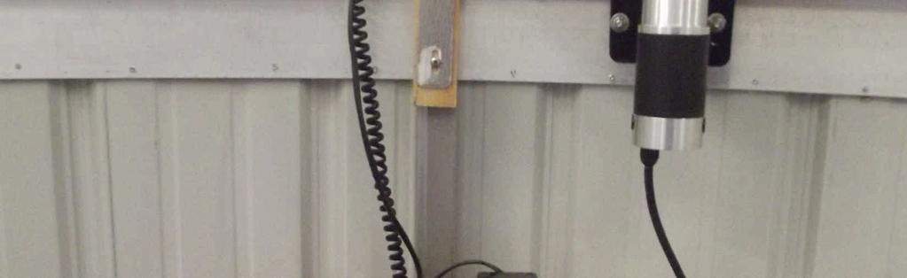
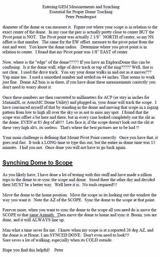
28 Connecting the Control Boxes to the Dome Hardware The Photos on this page shows a typical 8 Dome Rotation setup. You can see the tic counter lined up with the holes in the drive track and how it connects to the control box. You can see 2 copper strips mounted onto the drive track just to the left of the tic counter, they are used to send current to charge the battery in a Dome with shutter operation. There are also 2 copper strips on the face of the tic counter that make contact with the 2 copper strips on the drive track when in the parked position. At the bottom of the picture you see a typical setup for the mounting of the system, the battery on the left the control box on the top right and a battery charger on the bottom left.

29 EDII Rotation & Shutter Layout
30 The box on top in the photo below is the Shutter Control Box the Control Box on the bottom is the Rotation Control Box. Depending on when your control box was made it may have pig tails with Molex connectors or the connections are right in the box itself. The RJ connecters are always the same layout in every box.


31 Start by plugging in the Rotation Control Box Serial Cable. It can be the Serial to USB cable supplied or it can be just a serial cable you have if your computer has a serial port on it. This is also the connection you would use to connect the control box to your computer to check or update the firmware. Next you would plug in the tick and home sensor cord, it is an RJ11 connection to the left of the serial port connection on the Rotation Control box. The Tic & Home Sensor would normally be installed in the Dome when doing this procurer. There is a hand paddle also, This is used to rotate the Dome manually during set up (but if done wile tracking a star it will disrupt the timing and you will lose tracking of the star and will have to turn the program off and restart start the program to continue tracking the star.) Tic & Home Sensor Motor Cable Hand Paddle Tic & Home Sensor Serial to USB Cable Power & Motor Cable


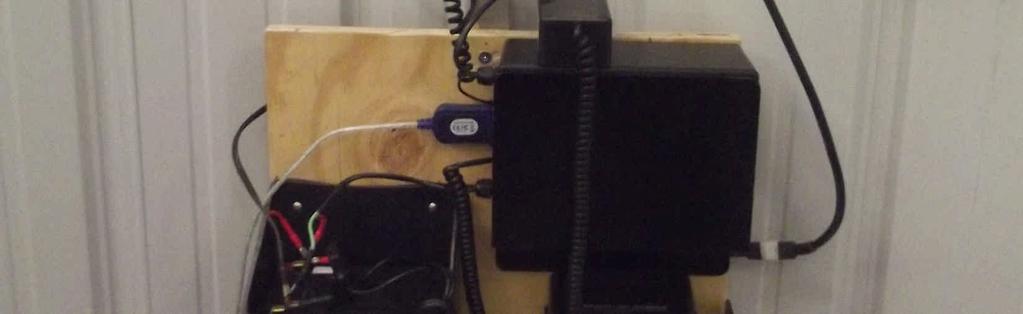
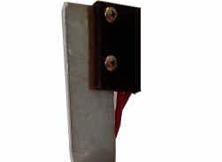
32 The picture below shows what it should look like when everything is connected inside the Dome. Here you see the rotation motor plugged into the control box and the control box plugged into the power supply, In this photo you also see the charging system mounter to the mounting ring, it has the home position sensor mounter to it also, If you are not fully automated there is an arm with the sensor mounted to it and you would mount the magnet to the drive track as seen in the photo below. (Note this photo show one of the older control boxes we used, but the new box connects the same way.)
 Plug the RJ11 cables into there proper connection ports and to the modular jacks on the limit switches.")

33 The Shutter Control box below is the latest control box it has a (Lower Door Power and RJ11 connector jack) a RJ11 Paddle jack is the Middle port and an (Upper Door Power and RJ11 connector.) Plug the RJ11 cables into there proper connection ports and to the modular jacks on the limit switches. There is a port for a hand paddle also which can be used to open and close the shutter doors manually. The Shutter Control Box commutates with the Rotation Control box wirelessly and so the Rotation box needs to be commutating with the computer in order for the wireless commutations between the two boxes to work. You can use the paddle to open or close the shutter doors but you need to cycle them through completely, you can not stop midway through and return to the starting position. When you finish setting up you lay the cables out the notches in the front of the box. Modular Jack Modular Jack Modular Jack Modular Jack on control board Modular Jack on control board Hand Paddle Port Shutter Door Connection for motor Shutter Door Connection for motor Power cable 12vdc


34 Setting Up the Telescope in the AstroMC Program After you have the basics set up in the Astro Mc program the next step is to match the Telescope position to the Dome Slit or opening. First with the Astro Mc program open click on the ObsCtl drop down button on the upper left corner of the program window. Click on setup to open the setup window then check the Astro MC Manages Dome AZ calculations, then the Dome utility window open and you click the Setup button to open the Telescope and Mount Setup. Click the Select Scope button in the upper left corner and select your scope.

35
36
37
IRF90 - Rotating Focuser
 IRF90 - Rotating Focuser Part # 600180 REV092111 Page 1 Contents Introduction and Overview... 3 Limitations... 3 Packing List... 4 Installation... 5 Remove Existing Focuser... 5 Installing the Rotating
SMM501/501-H (Surveillance Mode Module) Ford Police Interceptors (Sedan and SUV)
 Ford Police Interceptors (Sedan and SUV)") An ISO 9001:2008 Registered Company SMM501/501-H (Surveillance Mode Module) 2013-2014 Ford Police Interceptors (Sedan and SUV) Introduction The SMM501/501-H is intended for 2013 and 2014 Ford Police Interceptors
An ISO 9001:2008 Registered Company SMM501/501-H (Surveillance Mode Module) 2013-2014 Ford Police Interceptors (Sedan and SUV) Introduction The SMM501/501-H is intended for 2013 and 2014 Ford Police Interceptors
Pulsed Frequency TM. Joint PEMF Software Download, Installation and User Guide
 Pulsed Frequency TM Joint PEMF Software Download, Installation and User Guide Account Registration... 3 Create an Account... 4 Download the Software... 6 Install the Software... 7 Connect JOINT PEMF to
1. Introduction P Package Contents 1.
 1 Contents 1. Introduction ------------------------------------------------------------------------------- P. 3-5 1.1 Package Contents 1.2 Tablet Overview 2. Using the Tablet for the first time ---------------------------------------------------
Total Connect 2.0 Online Help
 Security Events Users Locations Video Hints for use. After logging in hit F11 to toggle full screen mode. Hover over icons for tool tip help. Upon the initial login, control panel data should be imported
Pulsed Frequency TM. Joint PEMF Software Download, Installation and User Guide
 Pulsed Frequency TM Joint PEMF Software Download, Installation and User Guide Contents Account Registration... 3 Create an Account... 4 Download the Software... 6 Chrome... 7 Edge... 8 Firefox... 10 Install
Optec Pyxis Help 1 / 56
 Optec Pyxis Help 1 / 56 Table of contents Introduction... 3 License... 4 What's new... 6 Getting Started... 7 System requirements... 7 Installation... 9 Setup... 10 Adding new Instances... 14 Troubleshooting...
Pulsed Frequency TM. Plasma Software Download, Installation and User Guide
 Pulsed Frequency TM Plasma Software Download, Installation and User Guide Contents Account Registration... 3 Create an Account... 4 Download the Software... 6 Install the Software... 9 Connect PLAZOMICS
ipcam-wo Wireless Outdoor
 POWER NETWORK Total Connect Online Help Guide for: ip Cameras ipcam-wi Wireless Indoor ipcam-pt Pan and Tilt ipcam-wo Wireless Outdoor 800-08456 3/11 Rev. A TRADEMARKS Honeywell is a registered trademark
Using GIGABYTE Notebook for the First Time
 Congratulations on your purchase of the GIGABYTE Notebook! This Manual will help you to get started with setting up your notebook. For more detailed information, please visit our website at http://www.gigabyte.com.
MEEM Memory Ltd. User Guide ios
 MEEM Memory Ltd. User Guide ios 1. WHAT IS MEEM? MEEM is a mobile phone charger and backup device in one cable. So every time you charge your phone you back up the data stored on it to the MEEM cable itself.
Click Here to Begin OS X. Welcome to the OS X Basics Learning Module.
 OS X Welcome to the OS X Basics Learning Module. This module will teach you the basic operations of the OS X operating system, found on the Apple computers in the College of Technology computer labs. The
DIGITAL GAME CAMERA. Model DC-6SS
 DIGITAL GAME CAMERA Model DC-6SS CONTENTS: WELCOME... 2 GETTING STARTED... 3 MOTION DETECTOR... 4-8 CAMERA MENUS... 9-10 CONNECTING TO A COMPUTER... 11 TROUBLESHOOTING... 12 WARRANTY... 13 Leaf River Outdoor
Instructions for Installing FlashUpdate and Downloading Updates for Super Buddy Satellite Meter
 Instructions for Installing FlashUpdate and Downloading Updates for Super Buddy Satellite Meter Updates to the Field Guide and to the instrument firmware are available from the Applied Instruments website.
TOC F1 Operations Manual
 TOC F1 Operations Manual - 1 - General Description The TOC F1 is a single channel wireless lens control system. The system can be used on most broadcast or cinema lenses. The TOC F1 includes a hand held
PC Focus Control Operator's Guide
 PC Focus Control Operator's Guide Copyright 2008 JMI Telescopes Jim's Mobile, Incorporated 8550 West 14th Avenue Lakewood, CO 80215 U.S.A. Phone (303) 233-5353 Fax (303) 233-5359 Order Line (800) 247-0304
Installing the Focus Motor
 The MicroTouch Autofocuser is designed to work with Feathertouch Focusers from Starlight Instruments. It allows automatic focusing with CCD and DSLR cameras. Included is FocusMax software to automatically
Introduction. This manual is divided into seven parts:
 Introduction The MAGPiX B350 is a digital camera with a specially designed 5x telescopic lens. Combined with its very high-speed shutter, the MAGPiX B350 produces amazing freeze-frame action pictures.
WVL2 Wireless Vehicle Link 2 Installation and Setup Manual
 WVL2 Wireless Vehicle Link 2 Installation and Setup Manual Chapter 1: Introducing the Wireless Vehicle Link 2...1 WVL2 Components...2 Component Checklist...3 Product Specifications...4 System Requirements...5
1. Introduction P Package Contents 1.
 1 Contents 1. Introduction ------------------------------------------------------------------------------- P. 3-5 1.1 Package Contents 1.2 Tablet Overview 2. Using the Tablet for the first time ---------------------------------------------------
Installing the SDM Program
 Quick Start This guide is for people who just want the basics for getting started with StereoData Maker (SDM) to take digital stereo photos. There are other guides that will give you intermediate and advanced
Black Maverick Covert Scouting Camera Instruction Manual
 Black Maverick Covert Scouting Camera Instruction Manual Page1 Table of Contents Camera button info diagram: (Fig. 1)...4 Installing the batteries..5 Installing the SD card....5 Understand the main screen
Basic Computer and Mouse Skills Windows 10
 Basic Computer and Mouse Skills Windows 10 Hardware--is a term for the physical parts of the computer. The computer consists of four basic pieces of hardware. The Monitor The monitor displays the content
Installing LE History Record Reader program software.
 INSTALLATION & OPERATING INSTRUCTIONS FOR THE LE HISTORY RECORD READER These Instructions will inform you on how to install software to use the RS-232/USB Isolator- Adapter and your LE History Record Reader
Instruction Sheet Updating SmartPAC 2 Firmware
 Instruction Sheet Updating SmartPAC 2 Firmware This document shows you how to update SmartPAC 2 firmware, using a USB disk, and load SmartPAC 2 firmware installed on a replacement Compact Flash (CF) card.
Datalogging IAQ Meter Instruction Manual
 Datalogging IAQ Meter 800050 Instruction Manual Datalogging IAQ Meter 800050 Copyright 2014 by Sper Scientific ALL RIGHTS RESERVED Printed in the USA The contents of this manual may not be reproduced or
MCS-TOUCHSCREEN Auto Disk Clean up
 APP093 - MCS-Touchscreen Error 16 Auto Diskcleanup Procedure Micro Control Systems APPLICATION NOTE APP-093 MCS-TOUCHSCREEN Auto Disk Clean up Revision History Date Author Revision Description 07/31/2014
Installation Guide for. Phase One ixg Camera. Developed for Phase One Cultural Heritage, Scientific and Industrial Imaging Solutions
 Installation Guide for Phase One ixg Camera Developed for Phase One Cultural Heritage, Scientific and Industrial Imaging Solutions Installation Guide for Phase One ixg Camera Developed for Phase One Cultural
Active Power Programmer Instructions
 Active Power Programmer Instructions Installation 1. Before you install the software, DO NOT PLUG the devices usb port into your computer. You will be ask to do this later in the installation 2. Run the
Pulsed Frequency TM. Joint PEMFBasic Software Download, Installation and User Guide
 Pulsed Frequency TM Joint PEMFBasic Software Download, Installation and User Guide Contents Account Registration... 3 Create an Account... 4 Download the Software... 6 Chrome... 7 Edge... 8 Firefox...
The port replicator may have features that are not supported by your computer.
 Please refer to the product label for the HP product number and serial number. This is useful information if you ever need to contact technical support. Getting Started This section identifies the visible
ASTRO-PHYSICS GTO CONTROL BOX FOR SERVO DRIVE Model GTOCP1
 ASTRO-PHYSICS GTO CONTROL BOX FOR SERVO DRIVE Model GTOCP1 GTO CONTROL BOX GTOCP1 The GTO control box contains all of the circuitry to drive the two servo motors and the logic required to navigate the
Firmware install with Windows XP
 Firmware install with Windows XP Step 1. Go to our website www.midnitesolar.com and Left Click on Firmware. Step 2. Left Click on Download Firmware. Step 3. Read the Notes in red first and then Left Click
INTERFACE & SOFTWARE GUIDE
 TM INTERFACE & SOFTWARE GUIDE Wireless Remote Display USB Converter Battery Sensor Setup DataLogger Software r e m o t e i n t e r f a c e escape enter status w w w. s k y s t r e a m e n e r g y. c o
VP- X Pro & VP- X Sport
 VP- X Configurator Release Notes As of version 1.6 (May 13, 2013) This document updated October 31, 2013 Contents 1. Models...1 2. Updating the VP-X Pro and Sport firmware (Automatic)...1 3. Software Upgrade
The following documents are included with your Sony VAIO computer.
 Documentation The following documents are included with your Sony VAIO computer. Printed Documentation Quick Start Guide Describes the process from unpacking to starting up your VAIO. Troubleshooting and
Installing the Focus Motor
 The MicroTouch Wireless Autofocuser is designed to work with Feathertouch Focusers from Starlight Instruments. It allows automatic focusing with CCD and DSLR cameras. Included is FocusMax software to automatically
READ ME FIRST Windows 98/ME/2000
 READ ME FIRST Windows 98/ME/2000 *DSL Equipment Installation Guide: Alcatel Speed Touch PC *Digital Subscriber Line Part Number: AlcatelPC9x02A Version 1.2-A Table of Contents Follow Steps 1 through 7
* IMPORTANT * REGISTERING YOUR MACHINE
 * IMPORTANT * REGISTERING YOUR MACHINE Thank you for your purchase of the Keyline 994 Laser. Before continuing with machine setup and use, please complete the following; COMPLETE PRODUCT REGISTRATION FORM
NERGY SIREN CONFIGURATION. Friday, May 06, 2016 Version 1.02
 NERGY SIREN CONFIGURATION Friday, May 06, 2016 Version 1.02 Author Date Version Description SD 7/1/2014 1.00 Original Document JD 7/8/2014 1.01 Changes for public release SD 5/6/2016 1.02 Updates for SoundOff
Ice Cam Covert Scouting Camera Instruction Manual
 Ice Cam Covert Scouting Camera Instruction Manual Page1 Page2 Table of Contents Camera button info diagram:..4 Installing the batteries & SD card:...5 Understanding the main screen info:....6 Accessing
CellSync Manager. User Manual F8V7D006-SS F8V7D008-SS. Get online and synchronize anywhere. Web Access. Phone Book Manager
 CellSync Manager Get online and synchronize anywhere Web Access Phone Book Manager User Manual F8V7D006-SS F8V7D008-SS TABLE OF CONTENTS Introduction...2 Interactive Phone Menu...3 LG 5350 CellSync Software
TouchKit Touch Panel User manual for Windows9X/ME Version: 3.1.4
 TouchKit Touch Panel User manual for Windows9X/ME Version: 3.1.4 TouchKit Touch Panel v3.1.4 0 CONTENT CHAPTER 1. TOUCH PANEL CONTROLLER... 2 1.1 CONTROLLER... 2 1.2 SPECIFICATIONS AND FEATURES... 3 CHAPTER
EXM Configuration Tool EXM System Configuration Instructions
 EXM Configuration Tool EXM System Configuration Instructions 1302 WEST BEARDSLEY AVE ELKHART, IN 46514 1-574-295-8330 1-800-346-0250 98510000 REV B 2014 ELKHART BRASS MFG. CO., INC. WWW.ELKHARTBRASS.COM
DriveWizard Plus Instruction Manual
 DriveWizard Plus Instruction Manual To properly use the product, read this manual thoroughly. MANUAL NO. TOEP C730600 20C Table of Contents Safety Symbols and Markings...4 Manual Overview...5 Related Manuals...5
Hi-Res 8 Wi-Fi Digital Picture Frame with MP3 player Table of Contents
 Hi-Res 8 Wi-Fi Digital Picture Frame with MP3 player Table of Contents Before Using the Digital Picture Frame...3 Introduction...3 Features and Specs...3 Package contents...4 Digital Picture Frame Layout...5
Handout Objectives: a. b. c. d. 3. a. b. c. d. e a. b. 6. a. b. c. d. Overview:
 Computer Basics I Handout Objectives: 1. Control program windows and menus. 2. Graphical user interface (GUI) a. Desktop b. Manage Windows c. Recycle Bin d. Creating a New Folder 3. Control Panel. a. Appearance
FREEDOM-Pad Installation and Operation
 FREEDOM-Pad Installation and Operation Quick Start Steps for installing FREEDOM-Pad Page 2 Desktop Install Overview Page 2 Mobile Device Installation Overview Page 2 Activating the Battery Page 2 Resetting
Trouble shooting the DeskCNC controller:
 Checking for a functional card. 1) Unplug/Disconnect all connections to the I/O and step and direction pins/terminals. 2) Apply regulated 5vdc to the +5 and gnd terminals. CHECK FOR CORRECT POLARITY WITH
CDR Wireless / SDX Software Installation Guide
 CDR Wireless / SDX Software Installation Guide Schick Technologies, Inc. 30-00 47 th Avenue Long Island City, NY 11101 (718) 937-5765 (718) 937-5962 (fax) PART NUMBER B1051504 REV. Copyright 2004 by Schick
Quick Installation Guide
 V50.02 Model: FI8918W Quick Installation Guide Indoor Pan/Tilt Wireless IP Camera Black White For Windows OS ------- Page 1 For MAC OS ------- Page 14 Quick Installation Guide For Windows OS Package Contents
10 How to Setup a Home or Small Network
 How to Setup a Home or Small Network Objectives.1 Installing a Network Interface Card (NIC).2 Installing Network Components.3 Identifying Ports and Cable Types.4 Preparing Straight-through Network Cables.5
Driver Installation. Getting Started for Windows user (Setting up your Robot)
") Getting Started for Windows user (Setting up your Robot) Get the drivers and download the software to make your robots go! Programmer Driver Arduino Software IDE Ringo & Wink Software Libraries Driver
Getting Started for Windows user (Setting up your Robot) Get the drivers and download the software to make your robots go! Programmer Driver Arduino Software IDE Ringo & Wink Software Libraries Driver
TouchKit TouchScreen Controller User Guide for Windows 2000 / XP Version: 3.2.4
 TouchKit TouchScreen Controller User Guide for Windows 2000 / XP Version: 3.2.4 TouchKit Guide for Win2000/XP v3.2.4 0 CONTENT CHAPTER 1. TOUCH PANEL CONTROLLER...2 1.1 CONTROLLER...2 1.2 SPECIFICATIONS
Technical Information
 Technical Information DATE: January 16, 2014 MODEL: RSP 1570, RSX 1550, RSX 1560 Main Software Upgrade Instructions The RSP-1570, RSX-1550 and RSX-1560 have three separate software modules main software,
Product User Guide. OctProcessV2 and QuadProcessV2. QuadProcessV2-3A 4-Channel Low Level DC Current
 OctProcessV2-3A 8-Channel Low Level DC Current OctProcessV2-30mA 8-Channel Low Level DC Current OctProcessV2-160mA 8-Channel Low Level DC Current QuadProcessV2-3A 4-Channel Low Level DC Current QuadProcessV2-30mA
Studuino Programming Environment Manual
 Studuino Programming Environment Manual Ver 0.9.7 Jun. 02, 204 This manual explains the Studuino Programming Environment and how to use it. As the Studuino Programming Environment develops, this manual
PhotoKeeper User s Manual
 PhotoKeeper User s Manual 20071226 20080404 Table of Contents CONGRATULATIONS on your purchase of a Polaroid PhotoKeeper. Please read carefully and follow all instructions in the manual and those marked
Quick Start. Chapter. In This Chapter:
 Chapter Quick Start In This Chapter: Getting to Know Windows.... - Installation of irectsoft 6.... - Getting Started.... -8 Welcome to irectsoft00.... - Begin Editing a Program.... -4 Establish the Communication
Pulsed Frequency TM. MR7 Software Download, Installation and User Guide
 Pulsed Frequency TM MR7 Software Download, Installation and User Guide Contents Account Registration... 3 Create an Account... 4 Download the Software... 6 Install the Software... 8 Connect MR7 to Your
Frequently Asked Questions
 FAQs 10010410NC-RR Frequently Asked Questions Connecting Your Valet to the Internet 1 What computer operating systems does the Valet/Valet Plus support? 1 Why can t I connect my computer or device to my
Chapter 3 Operating instructions
 Chapter 3 Operating instructions Summary This chapter describes the how to control and navigate through the TVR 30 s menus and options. Content Control interfaces 10 Controlling the TVR 30 10 Front panel
HSIP2 User Manual. ios Application Android Application PC Setup
 HSIP2 User Manual ios Application Android Application PC Setup Please read all instructions carefully before use to get the most out of your HSIP2 Wireless Surveillance Camera. The design and features
HSIP2 User Manual. ios Application Android Application PC Setup
 HSIP2 User Manual ios Application Android Application PC Setup Please read all instructions carefully before use to get the most out of your HSIP2 Wireless Surveillance Camera. The design and features
GEN 6 LOCKPICK INSTALLATION OPTIONS COPYRIGHT 2010 COASTAL ELECTRONIC TECHNOLOGIES, INC.
 AFTERMARKET FRONT/BABY CAMERA VIDEO CONNECT HERE FRONT/BABY CAM POWER TO LOCKPICK RED W/BLACK STRIPE WIRE TO LOCKPICK BLACK GROUND WIRE UNPLUG ORIGINAL RADIO CONNECTORS THEN PLUG IN HERE PLUG AND PLAY
Pulsed Frequency TM. PlasmaBasic Software Download, Installation and User Guide
 Pulsed Frequency TM PlasmaBasic Software Download, Installation and User Guide Contents Account Registration... 3 Create an Account... 4 Download the Software... 6 Chrome... 7 Edge... 8 Firefox... 10 Install
X-CAM A10-3H 3 Axis Gimbal for GOPRO. User Manual ( V2.00 )
") X-CAM A10-3H 3 Axis Gimbal for GOPRO User Manual ( V2.00 ) The X-CAM A10-3H 3 Axis Gimbal has been setup and calibrated for use with GOPRO cameras, it is ready to use straight from the box. Specifications:
X-CAM A10-3H 3 Axis Gimbal for GOPRO User Manual ( V2.00 ) The X-CAM A10-3H 3 Axis Gimbal has been setup and calibrated for use with GOPRO cameras, it is ready to use straight from the box. Specifications:
HVR LINE INSTALL GUIDE
 HVR LINE INSTALL GUIDE 4.9.07 HVR v2.4.1 455 E. Industrial Drive P.O. Box 94 Hartland, WI 53029 Technical Support: 262.369.8798 Sales & Service: 262.369.8797 efax: 312.602.1356 www.visioncontrols.net Basic
WHAT YOU LL NEED TABLE OF CONTENTS. Second Shooter Plus Slider Motor Mount Camera Control Cable (or external intervalometer)
") SECOND SHOOTER PLUS USER GUIDE WHAT YOU LL NEED Second Shooter Plus Slider Motor Mount Camera Control Cable (or external intervalometer) TABLE OF CONTENTS The Controller... 2 Getting Started: Hardware
SECOND SHOOTER PLUS USER GUIDE WHAT YOU LL NEED Second Shooter Plus Slider Motor Mount Camera Control Cable (or external intervalometer) TABLE OF CONTENTS The Controller... 2 Getting Started: Hardware
FAC-R Frequency to Analog Converter Installation, Operating & Maintenance Manual
 COMPANY FAC-R Frequency to Analog Converter Installation, Operating & Maintenance Manual 2017 AW-Lake Company. All rights reserved. Doc ID:FACMAN12082017 V4 Table of Contents Product Overview...3 Operation...3
One Click Technologies Limited. Customisation Cable & Software Manual. Part Number AVCP01
 One Click Technologies Limited Customisation Cable & Software Manual Part Number AVCP01 1 Installation One Click Customisation Cable & Software Manual IMPORTANT Use the AVCP01 customisation cable only
KNOW THE OPTIONS for your next hunt!
 KNOW THE OPTIONS for your next hunt! The Day6 PlotWatcher Time Lapse HD Video Camera records up to 84 hours of activity at a potential hunting location onto a USB drive. All of the activity can then be
Performer to DP2 Hot Folder Reference Manual Rev There is only one file involved with installing the Performer to DP2 Hot Folder.
 Performer to DP2 Hot Folder Reference Manual Rev. 07.11.05 Install Files: There is only one file involved with installing the Performer to DP2 Hot Folder. The installer file is named PP2DP2_1.x.x.EXE.
Paramount Electronics Replacement Instructions
 Paramount Electronics Replacement Instructions Revision 1.7, October 2017 2017 Software Bisque, Inc. All rights reserved. Contents Replacing Paramount Electronics... 3 Step 1: Save Existing Control System
Finding information on your computer
 Important Be sure to create recovery discs immediately after your computer is ready for use because there are no recovery discs provided with the computer. For instructions on how to create the recovery
Using GIGABYTE Notebook for the First Time
 Congratulations on your purchase of the GIGABYTE Notebook. This manual will help you to get started with setting up your notebook. The final product configuration depends on the model at the point of your
The Pipe Reader. Please read this Instruction Manual
 THE PIPE READER The Pipe Reader Please read this Instruction Manual Contents Contents... 2 Quick start guide for the NLIS Pipe Reader... 4 Installation of software... 5 Standard Reader (USB Cable) Installation...
DODGE Challenger Charger Journey. 6-Pin Video Input Cable 6-Pin Audio In/Out Cable GPS Magnetic Antenna
 CHRYSLER 2011-2014 300c DODGE 2011-2014 Challenger 2011-2014 Charger 2011-2014 Journey FIAT 2011-2014 Freemont Plug and Play connectors make installation simple and easy. Utilizes the latest mapping version
Welcome to COMP 388 Tutorial on:
 Welcome to COMP 388 Tutorial on: 5.0 By: Chris Abplanalp TABLE OF CONTENTS 1. What are the ways to go back to the originally working window when accidentally switched to another program by pushing some
Contents. Emma User Guide
 Emma User Guide Emma User Guide i Contents Getting Started with Emma... 2 Prerequisites... 2 Installation... 4 Installing Emma... 4 Uninstalling Emma... 4 Start and registration... 4 Starting Emma... 4
XTS36 Touch Screen X10 Lighting Control System Operating Manual
 X10 Lighting Control System Operating Manual 1 X10 Lighting Control System Operating Manual Rev 1.2 Introduction...3 Software Overview...4 How to Install...5 USB Driver Installation...6 Configuration Software
sbdconfig.exe Software
 Installing the Please Note: The software only works with the 3200 or 3300 digital clocks series. Sapling s USB to RS485 converter needs to be purchased separately. Other USB to RS485 converters will not
DATABANK WEB SITE Cod. M0251 Rev. 2.2 (06/2018) User Manual 1. FIRST DATABANK INSTALLATION 2. DATABANK UPDATE
 User Manual 1. FIRST DATABANK INSTALLATION 2. DATABANK UPDATE") User Manual 1. FIRST DATABANK INSTALLATION 2. DATABANK UPDATE INDEX 0 FOREWORD... 3 1 SETTINGS TO ENABLE THE POP-UPS... 5 1.1 If you have Chrome... 5 1.1 If you have Firefox... 7 1.2 If you have Internet
User Manual 1. FIRST DATABANK INSTALLATION 2. DATABANK UPDATE INDEX 0 FOREWORD... 3 1 SETTINGS TO ENABLE THE POP-UPS... 5 1.1 If you have Chrome... 5 1.1 If you have Firefox... 7 1.2 If you have Internet
LinkMotion and CorelDraw 9, 10, 11, 12, X3, X4, X5, X6, X7 and X8:
 LinkMotion and CorelDraw 9, 10, 11, 12, X3, X4, X5, X6, X7 and X8: After you install LinkMotion software and set up all settings launch CorelDraw software. Important notes: Solustan s LinkMotion driver
MallinCam Micro Extended Control Software
 MallinCam Micro Extended Control Software Overview This is a description of the MallinCam Micro Extended Control (MMEC) software for the MallinCam Micro video camera for Astronomy. This is a Windows based
Getting Started. Here's how to get started using your Zip 250 drive: 1. Unpack the Zip 250 drive and accessories.
 Getting Started IMPORTANT! Before installing or using your Zip 250 drive, read and follow the USB guidelines to ensure reliable performance of your USB devices. Here's how to get started using your Zip
Instructions for Installing FlashUpdate and Downloading Updates for NPRT 2200 Noise Power Ratio Test Set
 Instructions for Installing FlashUpdate and Downloading Updates for NPRT 2200 Noise Power Ratio Test Set Updates to the instrument firmware are available from the Applied Instruments website. Requirements
TSMIU Wireless Bridge Installation and Configuration
 ation uration EPM Software must be 7.6.0.16 or greater and latest 750-E700B MIU code Hardware Installation 1. To install wireless bridge / bracket assembly and antenna, the MIU must be turned off and the
Digivu Quick Start Guide. Digivu User Instructions
 Digivu Quick Start Guide Digivu User Instructions Page - 2 Digivu User Instructions Page - 3 Table of contents Quick Start Guide 2 Digivu Functions 6 Connecting to a Vehicle Unit 6 Digivu Internal Memory
& Technical Specifications
 User Manual & Technical Specifications User manual Contents Pidion BM-170 Technical specifications... 2 Micro Rolltalk basic package... 3 Micro Rolltalk functions and buttons... 3 Preparing Micro Rolltalk...
Setup and Activation Guide for the TravelNet Data/Voice Terminal
 Setting up your Carrier Account. Setup and Activation Guide for the TravelNet Data/Voice Terminal Your TravelNet-DV requires both a data plan for internet service and a voice plan for analog phone service.
ASSAN ESC PC Interface Software User s Guide
 ASSAN ESC PC Interface Software User s Guide Dear customer, Welcome to use ASSAN ESC PC Connector and Interface Software. It allows of the Electronic Speed Controller programming in the desktop PC and
Enter your Appserv username and password to sign in to the Website
 Appserv Desktop Access Logging on from a Windows 10 Device Step 1. To sign in to the Appserv Desktop Access website, either enter the following address into the Microsoft Edge browser address bar, or click
Pulsed Frequency TM. EM272/EM272A Software Download, Installation and User Guide
 Pulsed Frequency TM EM272/EM272A Software Download, Installation and User Guide Account Registration... 3 Create an Account... 4 Download the Software... 6 Install the Software... 7 Connect EM272 / EM272A
1 Drobo 8D User Guide Before You Begin Product Features at a Glance Checking Box Contents... 9
 Drobo 8D User Guide 1 Drobo 8D User Guide... 6 1.1 Before You Begin... 7 1.1.1 Product Features at a Glance... 8 1.1.2 Checking Box Contents... 9 1.1.3 Checking System Requirements... 10 1.1.3.1 Operating
TouchKit TouchScreen Controller User Manual for Windows NT4 Version: 3.4.0
 TouchKit TouchScreen Controller User Manual for Windows NT4 Version: 3.4.0 1 CONTENT CHAPTER 1. TOUCH PANEL CONTROLLER 2 1.1 Controller 2 1.2 Specifications and Features 3 CHAPTER 2. INSTALLING TOUCHKIT
Product User Guide PR2000. PR2000 Pressure Data Logger with LCD
 Product User Guide PR2000 PR2000 Pressure Data Logger with LCD PR2000 Table of Contents Quick Start Steps... 3 Product Overview... 4 Software Installation... 5 Device Operation... 5 Computer Interface...
SmartPick Service Interface Installation, Setup and Event Log Download, Windows XP
 SmartPick Service Interface Installation, Setup and Event Log Download, Windows XP Seite: 1/15 1 Introduction 2 2 Flowchart 3 3 Installation 4 3.1 Installing the USB to Serial Adapter 4 3.2 Installing
How to use the HTC Desire C mobile devices
 How to use the HTC Desire C mobile devices Orientation First, a quick overview of your primary buttons and areas of your phone. A B C D E F G H A) Headphone Jack B) Power Hold down to power your phone
VisualPST 2.4. Visual object report editor for PowerSchool. Copyright Park Bench Software, LLC All Rights Reserved
 VisualPST 2.4 Visual object report editor for PowerSchool Copyright 2004-2015 Park Bench Software, LLC All Rights Reserved www.parkbenchsoftware.com This software is not free - if you use it, you must