MP3 audio amplifier. Build Instructions. Issue 2.0
|
|
|
- Albert Manning
- 5 years ago
- Views:
Transcription

1 MP3 audio amplifier Build Instructions Issue 2.0

: R1 is a 10K (brown, black, orange coloured bands) R2 is a 100 (brown, black, brown coloured bands) R3 is a 1 (brown, black, gold coloured bands)")

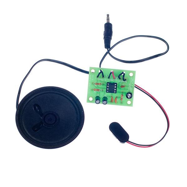
2 Build Instructions Before you put any components in the board or pick up the soldering iron, just take a look at the Printed Circuit Board (PCB). The components go in the side with the writing on and the solder goes on the side with the tracks and silver pads. You will find it easiest to start with the small components and work up to the taller larger ones. Step 1 Start with the three resistors (shown right): R1 is a 10K (brown, black, orange coloured bands) R2 is a 100 (brown, black, brown coloured bands) R3 is a 1 (brown, black, gold coloured bands) The text on the PCB shows where R1, R2 & R3 go. Make sure that you put the resistors in the right. Step 2 Solder the Integrated Circuit (IC) holder in to IC1. When putting this into the board, be sure to get it the right way around. The notch on the IC holder should line up with the notch on the lines marked on the PCB. Step 3 There are three ceramic disc capacitors, the smaller one is a 470pF capacitor and is printed with the number 471. This should be soldered into C1. The other two capacitors are 100nF capacitors and are printed with 104. These need soldering in to C2 and C3. Step 4 The other three capacitors are electrolytic capacitors, the two smaller capacitors are marked 100 F. Place these two capacitors in to the board where it is labeled C4 and C5. Make sure the device is the correct way around. The capacitors have a - sign marked on them which should match the same sign on the PCB. The bigger capacitor is a 220 F, which should be soldered in to C6. Step 5 The three connections to your amplifier PCB need to go through the strain relief holes as shown in the picture on the right. Start with the connection labeled Speaker. The kit is supplied with ½ a meter of twin cable with a 3.5mm Jack connector on one end. This cable will be used to connect both the speaker and the MP3 player. You will need to cut a length from the end that does not have the jack connector on which will be used to connect the speaker. Make sure you leave enough cable so that you have a long enough lead to connect your MP3 player! Take the piece of wire that you have cut off and strip the ends of the wire. Connect one end to the two terminals on the speaker and the other end to the board marked speaker. It does not matter which way around these connections go. The middle connection is for the power. The PP3 battery clip (shown left) should be attached to the power connection. Connect the red wire to + and the black wire to -.
3 Build Instructions (continued) The final connection is the audio input. Strip the insulation off the other end of the remaining cable that has the jack plug on. Run some solder in to the wire and trim the wire so only 2 or 3 mm of bare wire is left. Solder these wires into the board where it is labeled input. It doesn t matter which of the pair of wires goes each of the two pads. Step 6 The IC can now be put into the holder ensuring the notch on the chip lines up with the notch on the holder. Your amplifier is ready for use. You can use the volume control on your MP3 player to control how loud the amplifier is. Just make sure it s mid volume when you test the amplifier. Adding an on / off switch If you wish to add a power switch, don t solder both ends of the battery clip directly into the board, instead: Solder one end of the battery clip to the PCB, either black to - or red to +. Solder the other end of the battery clip to the on / off switch. Using a piece of wire, solder the remaining terminal on the on / off switch to the remaining power connection on the PCB. ing Your Amplifier PCB Carefully check the following before you insert the batteries: Audio equipment may become damaged if connected to an incorrectly built amplifier. the bottom of the board to ensure that: All holes (except the 4 large (3 mm) holes in the corners) are filled with the lead of a component. All these leads are soldered. Pins next to each other are not soldered together. the top of the board to ensure that: The three wires are connected to the right. The - on the capacitors match the same marks on the PCB. The colour bands on R1 are brown, black, orange & R2 are brown, black, brown. The battery clip red and black wires match the red & black text on the PCB. The notch on the IC is next to the power connection.
4 Fault finding flow chart Start Power up the board with it connected to a music source IC1 is in the right way around For dry joints on the power / speaker / input connectors The input connector is in the right IC1 for dry joints on one of the following pins 3, 4, 5, 6, or 7 IC1 for shorts between pins 3-4, 5-6, or 7-8 C1, C4, C5 & C6 for shorts C6 for dry joints C1 and C6 are in the correct No No Does it pop when the power is connected? Is the speaker making any kind of sound? The power clip & batteries are connected the right way around C1 is in the correct The speaker & power connections are in the right That resistor R3 is in the correct R3 for dry joints That C1 and C3 are in the correct C2 for dry joints No it s muffled or unintelligible noise Is the speaker playing the music clearly? IC1 for a short between pins 2-3 R1 & R2 are in the right. For a dry joint on C4, R2 or IC1 pin 2. IC1 for a short between pins 1&2 or 6&7 Quiet Is the volume as expected? Stop
5 How the Amplifier Works At the centre of the circuit is an audio amplifier Integrated Circuit or IC. Inside the IC are lots of transistors, which are connected together to allow the small input signal to be amplified into a more powerful output that can drive a speaker. All amplifiers need to use feedback to ensure the amount of gain stays the same. This allows the output to be an exact copy of the input just bigger. The gain is the number of times bigger the output is compared to the input, so if an amplifier has a gain of 10 and there is 1 volt on the input there will be 10 volts on the output. Before looking at how the feedback works, we first need to understand how a standard amplifier works. An operational amplifier has two inputs these are called the inverting (-) and non-inverting (+) inputs. The output of the operational amplifier is the voltage on the noninverting input less the voltage on the inverting input multiplied by the amplifiers gain. In theory an operational amplifier has unlimited gain so if the non-inverting input is a fraction higher than the inverting input (there is more + than -) the output will go up to the supply voltage. Change the inputs around and the output will go to zero volts. In this format the operational amplifier is acting as a comparator, it compares the two inputs and changes the output accordingly. Input Amp Gain x10 90% 10% Output With an infinite gain the amplifier is no good to amplify audio, which is where the feedback comes in. By making one of the input a percentage of the output the gain can be fixed, which allows the output to be a copy of the input but bigger. Now when the two inputs are compared and the output is adjusted, instead of it going up or down until it reaches 0 volts or V+, it stops at the point when the two inputs match and the output is at the required voltage. Looking at the circuit diagram for the audio amplifier it s not obvious where the feedback is, this is because inside the IC is a 6K resistor between the output (pin 5) and the gain setting input (pin 2). The internal 6K resistor and the 100 resistor (R2) on the gain setting pin make up a potential divider that feeds back approximately a sixtieth of the output. This fixes the gain so the output is about 60 times bigger than the input. Battery Input TBA 820M 3 2 C1 470pF C6 220µF C3 100nF C5 100µF R1 10K R2 100Ω C4 100µF R3 1Ω C2 100nF The rest of the components are needed as follows: C3 & C5 are connected across the supply to make sure it remains stable. The other capacitors have a filtering role, either to cut out high frequency noise or get the best out of the speaker.
DELUXE STEREO AMPLIFIER KIT
 ESSENTIAL INFORMATION BUILD INSTRUCTIONS CHECKING YOUR PCB & FAULT-FINDING MECHANICAL DETAILS HOW THE KIT WORKS CREATE YOUR OWN SPEAKER DOCK WITH THIS DELUXE STEREO AMPLIFIER KIT Version 2.0 Build Instructions
High Power (15W + 15W) Stereo Amplifier
 Stereo Amplifier") High Power (15W + 15W) Stereo Amplifier Build Instructions Issue 1.0 Build Instructions Before you put any components in the board or pick up the soldering iron, just take a look at the Printed Circuit
High Power (15W + 15W) Stereo Amplifier Build Instructions Issue 1.0 Build Instructions Before you put any components in the board or pick up the soldering iron, just take a look at the Printed Circuit
XYLOPHONE KIT ESSENTIAL INFORMATION. Version 2.0 CREATE YOUR OWN ELECTRONIC MUSICAL INTRUMENT WITH THIS
 ESSENTIAL INFORMATION BUILD INSTRUCTIONS CHECKING YOUR PCB & FAULT-FINDING MECHANICAL DETAILS HOW THE KIT WORKS CREATE YOUR OWN ELECTRONIC MUSICAL INTRUMENT WITH THIS XYLOPHONE KIT Version 2.0 Build Instructions
RECORD & PLAYBACK KIT
 ESSENTIAL INFORMATION BUILD INSTRUCTIONS CHECKING YOUR PCB & FAULT-FINDING MECHANICAL DETAILS HOW THE KIT WORKS ADD AN AUDIO MESSAGE TO YOUR PRODUCT WITH THIS RECORD & PLAYBACK KIT Version 2.1 Build Instructions
solutions for teaching and learning
 RKAmp1 Component List and Instructions PCB layout Constructed PCB Schematic RKAmp1 Stereo Amplifier Page 1 Description The RKAmp1 stereo amplifier PCB has been designed around the 2 x 1watt stereo amplifier
solutions for teaching and learning
 RKAmp3 Component List and Instructions PCB layout Constructed PCB Schematic RKAmp3 Stereo Amplifier Page 1 Description The RKAmp3 stereo amplifier PCB has been designed around the 2 x 7watt stereo amplifier
BLUETOOTH AMPLIFIER KIT
 PRODUCT INFORMATION BUILD INSTRUCTIONS CHECKING YOUR PCB & FAULT-FINDING MECHANICAL DETAILS HOW THE KIT WORKS CREATE YOUR OWN WIRELESS SPEAKER WITH THIS BLUETOOTH AMPLIFIER KIT Version 1.2 Index of Sheets
Electronics Construction Manual
 Electronics Construction Manual MitchElectronics 2018 Version 1 07/05/2018 www.mitchelectronics.co.uk CONTENTS Introduction 3 How To Solder 4 Resistors 5 Capacitors 6 Diodes and LEDs 7 Switches 8 Transistors
Installation/assembly manual for DCC/Power shield
 Installation/assembly manual for DCC/Power shield The DCC circuit consists of the following components: R1/R6 R2/R3 R4/R5 D1 C2 2 kω resistor ½ Watt (colour code Red/Black/Black/Brown/Brown) 10 kω resistor
Electronics Construction Manual
 Electronics Construction Manual MitchElectronics 2019 Version 3 04/02/2019 www.mitchelectronics.co.uk CONTENTS Introduction 3 How To Solder 4 Resistors 5 Capacitors 6 Diodes and LEDs 7 Switches 8 Transistors
STAGE INTERCOM KIT 1.1 SPECIFICATION. General: The lower section is a small power amplifier designed to drive headphones or a small 8ohm speaker.
 STAGE INTERCOM KIT Version 2.1.1 - March 2018 - EduTek Ltd 1.0 DESCRIPTION This intercom module comprises of two separate circuits sharing the same supply. The upper section is a pre-amplifier designed
1/Build a Mintronics: MintDuino
 1/Build a Mintronics: The is perfect for anyone interested in learning (or teaching) the fundamentals of how micro controllers work. It will have you building your own micro controller from scratch on
Micro USB Lamp Kit ESSENTIAL INFORMATION. Version 2.0 DESIGN A STYLISH LAMP WITH THIS
 ESSENTIAL INFORMATION BUILD INSTRUCTIONS CHECKING YOUR PCB & FAULT-FINDING MECHANICAL DETAILS HOW THE KIT WORKS DESIGN A STYLISH LAMP WITH THIS Micro USB Lamp Kit Version 2.0 Build Instructions Before
Assembly Guide. LEDs. With these assembly instructions, you can easily build your own SWT16. All required components are included in this kit.
 Assembly Guide With these assembly instructions, you can easily build your own SWT16. All required components are included in this kit. You need the following tools: soldering iron, wire cutter and solder.
PicoTurbine Mark 8.3 Generator Field Controller Kit
 PicoTurbine Mark 8.3 Generator Field Controller Kit Based on a design published in Home Power magazine by Richard Perez. Used with permission. Reprint of original article included with kit. An easy-to-build
The GENIE Light Kit is ideal for introducing simple lighting projects, such as an electronic die, a wearable badge or a night-time warning system.
 Introduction 1 Welcome to the GENIE microcontroller system! The GENIE Light Kit is ideal for introducing simple lighting projects, such as an electronic die, a wearable badge or a night-time warning system.
AUDIO AMPLIFIER PROJECT
 Intro to Electronics 110 - Audio Amplifier Project AUDIO AMPLIFIER PROJECT In this project, you will learn how to master a device by studying all the parts and building it with a partner. Our test subject:
These are the illustrated step-by-step guidelines for upgrading your Quad 306 with the Dada Electronics upgrade-kit.
 Quad 306 DIY illustrated guidelines version 1.1 These are the illustrated step-by-step guidelines for upgrading your Quad 306 with the Dada Electronics upgrade-kit. We will replace all electrolytic capacitors,
SRI-02 Speech Recognition Interface
 SRI-02 Speech Recognition Interface Data & Construction Booklet The Speech Recognition Interface SRI-02 allows one to use the SR-07 Speech Recognition Circuit to create speech controlled electrical devices.
TuBbika SMR-4-PLUS voicecard
 TuBbika SMR-4-PLUS voicecard Assembly instructions We assume you know soldering. If you don t, look first at this tutorial. Be patient! And if you have any doubt, head to the forum never be afraid to ask!
Chill Interface PCB Assembly Instructions
 ExcelValley Chill Interface PCB Waveblaster Module MIDI Interface Board Chill Limited Edition V2 Assembly Kit Standalone midi interface board for Waveblaster synthesizer modules. Suitable for most Waveblaster
Uzebox Kit Assembly Guide
 Uzebox Kit Assembly Guide V1.3 Page 1 of 18 Revision History Version Date Author Description 1.0 01-Nov-2012 A.Bourque Initial release 1.1 6-Nov-2012 A.Bourque Minor corrections 1.2 28-Jan-2014 A.Bourque
Post Tenebras Lab. Written By: Post Tenebras Lab
 Post Tenebras Lab PTL-ino is an Arduino comptaible board, made entirely out of through-hole components. It is a perfect project to learn how to solder and start getting into the world of micro controllers.
LushOne Inca Synth Module Build Instructions
 LushOne Inca Synth Module Build Instructions Getting started If you can build the LushOne base module then then building the Inca should be easy Remember: Accuracy and neatness is more important than speed
BuffaloLabs WiFi Lantern Assembly guide version 1
 BuffaloLabs WiFi Lantern Assembly guide version 1 Needed equipment: Solder iron Solder wire Cutter Wire stripper (optional) Hot glue gun Overview of the components (not including USB cable and box panels)
solutions for teaching and learning
 Circuit Construction Op-Amp Comparator Project The circuit diagram on the right is the circuit for your project, it is called an op-amp comparator circuit, it is called a comparator circuit as it compares
Assembly Instructions (8/14/2014) Your kit should contain the following items. If you find a part missing, please contact NeoLoch for a replacement.
 Your kit should contain the following items. If you find a part missing, please contact NeoLoch for a replacement.") NeoLoch NLT-28P-LCD-5S Assembly Instructions (8/14/2014) Your kit should contain the following items. If you find a part missing, please contact NeoLoch for a replacement. Kit contents: 1 Printed circuit
NeoLoch NLT-28P-LCD-5S Assembly Instructions (8/14/2014) Your kit should contain the following items. If you find a part missing, please contact NeoLoch for a replacement. Kit contents: 1 Printed circuit
Building the RGBW LED Controller
 Building the RGBW LED Controller A guide for the assembly and operation of your RGBW LED Controller. ver 3.1 Getting Started Parts list - You should have received the following parts: (1) Circuit Board,
Onwards and Upwards, Your near space guide Overview of the NearSys Two Sensor Temperature Array Figure 1. A complete Two Sensor Temperature Array
 The NearSys Two Sensor Temperature Array is a kit that permits a BalloonSat to measure two separate temperatures. When plugged into a flight computer like the BalloonSat Mini, the flight computer provides
Figure 1. A complete Temperature Sensor
 The NearSys Temperature Sensor is a kit that permits a BalloonSat to measure the temperature of the air, interior, or object the sensor itself is placed in contact with. When plugged into a flight computer
UF-3701 Power Board Construction Guide
 Page 1/5 Soldering and Part Placement See the Chapter 3 of the MIT 6270 Manual for information on electronic assembly, including soldering techniques and component mounting. Construction Information All
Using solderless breadboards
 Page 1 of 9 Using solderless breadboards This document describes how to use the solderless breadboards available in the experimental didactic lab (LED, previously LADISPE) of Politecnico di Torino. 1 Setting
Images Scientific OWI Robotic Arm Interface Kit (PC serial) Article
 Article") Images Scientific OWI Robotic Arm Interface Kit (PC serial) Article Images Company Robotic Arm PC Interface allows real time computer control and an interactive script writer/player for programming and
Images Scientific OWI Robotic Arm Interface Kit (PC serial) Article Images Company Robotic Arm PC Interface allows real time computer control and an interactive script writer/player for programming and
RC-210 Repeater Controller Assembly Manual
 Arcom Communications 24035 NE Butteville Rd Aurora, Oregon 97002 (503) 678-6182 arcom@ah6le.net RC-210 Repeater Controller Assembly Manual Hardware Version 3.0 Original Release Date September 13, 2004
IR TRANSMITTER BLOK PCB ASSEMBLY INSTRUCTIONS. Copyright EduTek Ltd Rev. 2
 IR TRANSMITTER BLOK PCB ASSEMBLY INSTRUCTIONS Copyright EduTek Ltd Rev. 2 Circuit Details The circuit is shown below with a parts list of components. Check through this list and identify each component.
The Sudden Storm Kit. by QRPme. Builder s Guide. version4.2. for. Sudden Storm ][ Ver4 (red pcb) Updated 01/10/2012
![The Sudden Storm Kit. by QRPme. Builder s Guide. version4.2. for. Sudden Storm ][ Ver4 (red pcb) Updated 01/10/2012](/thumbs/75/72448638.jpg "The Sudden Storm Kit. by QRPme. Builder s Guide. version4.2. for. Sudden Storm ][ Ver4 (red pcb) Updated 01/10/2012") The Sudden Storm Kit by QRPme Builder s Guide version4.2 for Sudden Storm ][ Ver4 (red pcb) Updated 01/10/2012 Open the can and the adventure begins 1 Organize the parts and take an inventory Bill of Materials
The Sudden Storm Kit by QRPme Builder s Guide version4.2 for Sudden Storm ][ Ver4 (red pcb) Updated 01/10/2012 Open the can and the adventure begins 1 Organize the parts and take an inventory Bill of Materials
Step 1 - Modifying the power-supply from 12 to 16 Volts Increasing the power-supply voltage to 16V increases the headroom and reduces distortion. Also
 Dada Electronics - Quad 33 Revision - Illustrated Guidelines V 2.4 First of all, thanks for your purchase of our upgrade kit! Hereunder, you will find the step-by-step guidelines for upgrading the Quad
Part 2: Building the Controller Board
 v3.01, June 2018 1 Part 2: Building the Controller Board Congratulations for making it this far! The controller board uses smaller components than the wing boards, which believe it or not, means that everything
RC210 Repeater Controller Assembly Manual
 Arcom Communications 24035 NE Butteville Rd Aurora, Oregon 97002 (503) 678-6182 arcom@ah6le.net http://www.arcomcontrollers.com/ RC210 Repeater Controller Assembly Manual Hardware Version 3.3 Reproduction
RKP08 Component List and Instructions
 RKP08 Component List and Instructions PCB layout Constructed PCB RKP08 Scematic RKP08 Project PCB Page 1 Description The RKP08 project PCB has been designed to use PIC microcontrollers such as the Genie
Step 1 The tools & the Components The tools you need: A good quality soldering iron with a fine point (max 30) Watt or a soldering-station. A desolder
 Watt or a soldering-station. A desolder") Upgrade/revision manual Quad 44 pre amplifier. V2.5 These are the illustrated step-by-step guidelines for upgrading your Quad 44 with the Dada Electronics upgrade-kits. The Quad 44 preamp was the first
Upgrade/revision manual Quad 44 pre amplifier. V2.5 These are the illustrated step-by-step guidelines for upgrading your Quad 44 with the Dada Electronics upgrade-kits. The Quad 44 preamp was the first
Code Practice Oscillator (CPO)
") Code Practice Oscillator (CPO) Overview Many thanks for your purchase of this code practice oscillator or CPO, this guide is intended to allow you to quickly get operational. The CPO comprises an approx.
Code Practice Oscillator (CPO) Overview Many thanks for your purchase of this code practice oscillator or CPO, this guide is intended to allow you to quickly get operational. The CPO comprises an approx.
Microsystems. SCI-6 Sound Card Interface Kit Version 1.09 January 2015
 UM Unified Microsystems SCI-6 Sound Card Interface Kit Version 1.09 January 2015 The SCI-6 interface was designed to be a low cost, high quality interface between your PC s sound card and radio transceiver.
Pacific Antenna Two Tone Generator
 Pacific Antenna Two Tone Generator Description Our Two Tone Generator kit provides two non-harmonic, sine wave signals for testing audio circuits Outputs of approximately 700Hz and 1900Hz and the combination
Attention: The connectors on the BMD16N are not normal network plugs. Never connect the decoder to a PC or any other network device!
 BMD16N version 1.2 Feedback decoder with 16 contacts for the S88-bus Compatible with a.o. Märklin Digital, Uhlenbrock Intellibox, Fleischmann Twin-Center and LDT HSI-88 Compatible with the s88-n standard
Uzebox Kit Assembly Guide
 Uzebox Kit Assembly Guide V1.7 Page 1 of 21 Revision History Version Date Author Description 1.0 01-Nov-2012 A.Bourque Initial release 1.1 6-Nov-2012 A.Bourque Minor corrections 1.2 28-Jan-2014 A.Bourque
QRPGuys Digital Dial/Frequency Counter
 QRPGuys Digital Dial/Frequency Counter First, familiarize yourself with the parts and check for all the components. If a part is missing, please contact us and we will send one. You must use qrpguys.parts@gmail.com
3 pyro output datalogger altimeter with an ATmega 328 microcontroller Kit assembly instructions
 3 pyro output datalogger altimeter with an ATmega 328 microcontroller Kit assembly instructions Version date Author Comments 1.0 29/05/2013 Boris du Reau Initial version Rocket Type Micro-max Model Mid
Solder the Harlequin, Revision F, March Solder the Harlequin - please read carefully (also the addendum!) before starting
 before starting") Solder the Harlequin, Revision F, March 2014 Page 1 of 8 Solder the Harlequin - please read carefully (also the addendum!) before starting You should check the kit for completeness (see addendum). If you
Solder the Harlequin, Revision F, March 2014 Page 1 of 8 Solder the Harlequin - please read carefully (also the addendum!) before starting You should check the kit for completeness (see addendum). If you
Morse Code Practice Oscillator
 Features Description Keyer speed range: Limited only by keying source True Sine wave tone output Tone Volume Control Tone Frequency Control Internal Speaker 1/8 External Speaker/Headphone Jack RCA Key
Arduino shield kit. 1) Low Pass Filter (LPF) kit (available for LF/MF/HF/VHF bands 2,200m to 6m)
 Low Pass Filter (LPF) kit (available for LF/MF/HF/VHF bands 2,200m to 6m)") Arduino shield kit 1. Introduction The QRP Labs Arduino shield kit is a versatile shield that can be used for various purposes. Write your own Arduino sketch to define the functionality! For example: 1)
Arduino shield kit 1. Introduction The QRP Labs Arduino shield kit is a versatile shield that can be used for various purposes. Write your own Arduino sketch to define the functionality! For example: 1)
LED Knight Rider. Yanbu College of Applied Technology. Project Description
 LED Knight Rider Yanbu College of Applied Technology Project Description This simple circuit functions as a 12 LED chaser. A single illuminated LED 'walks' left and right in a repeating sequence, similar
EXTENDED RECORD PLAYBACK KIT. Allows you to record and play messages of up to 8 minutes long.
 K8094P 1 ILLUSTRATED LUS TED ASSEMBLY MANUAL AL H8094IP 1 EXTENDED RECORD PLAYBACK KIT Allows you to record and play messages of up to 8 minutes long. The K8094 allows you to record and play messages of
Advanced Strobe 1.0 Kit
 Kit Instruction Manual Eastern Voltage Research, LLC December 2013, Rev 1 1 http://www.easternvoltageresearch.com Kit Introduction to the Kit Thank you for purchasing the Kit. If you are looking for a
OpenSprinkler v2.2u Build Instructions
 OpenSprinkler v2.2u Build Instructions (Note: all images below are 'clickable', in order for you to see the full-resolution details. ) Part 0: Parts Check Part 1: Soldering Part 2: Testing Part 3: Enclosure
BalloonSat Sensor Array
 BalloonSat Sensor Array The PICAXE-08M2 in the BalloonSat flight computer is a digital device. Being digital, it functions best with a series of on and off voltages and does not interact very well with
KAA Watt x 2 Class-D Audio Amplifier Kit
 KAA10021 50 Watt x 2 Class-D Audio Amplifier Kit This amplifier kit uses Texas Instruments TPA3116D2 stereo audio amplifier IC for driving speakers up to 50 watts @ 4 ohm per channel in stereo mode and
Build Your Own Home Security System
 Build Your Own Home Security System Student Lab Guide Engineering Teaching Laboratory Name Date Lab Partner(s) NEW TERMS Electric Circuit: Electric circuits are paths for transmitting electric current,
TKEY-1. CW touch key. (no electromechanical contacts) Assembly manual. Last update: June 20,
 Assembly manual. Last update: June 20,") TKEY-1 CW touch key (no electromechanical contacts) Assembly manual Last update: June 20, 2017 ea3gcy@gmail.com Updates and news at: www.ea3gcy.com Thanks for constructing the TKEY-1A CW touch key Have
TKEY-1 CW touch key (no electromechanical contacts) Assembly manual Last update: June 20, 2017 ea3gcy@gmail.com Updates and news at: www.ea3gcy.com Thanks for constructing the TKEY-1A CW touch key Have
Pacific Antenna Easy TR Switch Kit
 Pacific Antenna Easy TR Switch Kit Kit Description The Easy TR Switch is an RF sensing circuit with a double pole double throw relay that can be used to automatically switch an antenna between a separate
by illumicon APRSTRACKER Pietershoek XA Veldhoven The Netherlands fax
 by illumicon www.ezkits.eu APRSTRACKER Pietershoek 3 5503XA Veldhoven The Netherlands fax +31-40-2230020 Contents Introduction...3 Soldering Tips...3 Assembly...4 Schema...5 Connections...6 Adjustments...6
solutions for teaching and learning
 RKP18Motor Component List and Instructions PCB layout Constructed PCB Schematic Diagram RKP18Motor Project PCB Page 1 Description The RKP18Motor project PCB has been designed to use PIC microcontrollers
Universal Keying Adapter 3+
 Universal Keying Adapter 3+ The Universal Keying Adapter Version 3+ kit will allow you to key nearly any transmitter or transceiver with a straight key, electronic keyer, computer serial or parallel port
Button Code Kit. Assembly Instructions and User Guide. Single Button Code Entry System
 Button Code Kit Single Button Code Entry System Assembly Instructions and User Guide Rev 1.0 December 2009 www.alan-parekh.com Copyright 2009 Alan Electronic Projects Inc. 1. Introduction... 4 1.1 Concept
An open-source hardware+software project. For design files and additional documentation, please visit:
 An open-source hardware+software project. For design files and additional documentation, please visit: http://www.evilmadscientist.com/go/diavolino Support: http://www.evilmadscientist.com/forum/ Distributed
revolution How does the ibutton work? Full kit including PCB, PICAXE-08M chip and ibutton key. Spare ibutton Key
 AXE109S LOG020 Full kit including PCB, PICAXE-08M chip and ibutton key. Spare ibutton Key The ibutton is an electronic chip armoured in a 16mm stainless steel can. Because of this unique, durable package,
Connecting igaging DigiMAG Scales to the Caliper2PC Interface A step by step Guide
 What is an igaging DigiMAG Scale? The igaging DigiMAG are digital linear scales that are easily connectable to the Caliper2PC interface. They consist of two parts, the encoder and the readout unit. The
VG-305A AC Traffic Light Controller Kit
 Galak Electronics Electronic kits and components Website: GalakElectronics.com Email: sales@galakelectronics.com Phone: (302) 832-1978 VG-305A AC Traffic Light Controller Kit Thank you for your purchase
Parts List: Part # Tools List: Instructions:
 Parts List: Part # 1 pair of Dayton Audio B652s 300-652 1 Dayton Audio DTA-2 amplifier 300-385 1 MP3 module 320-350 1 7805 +5 VDC voltage regulator 7805 1 12 VDC 2A power supply 129-077 1 2.1 mm panel
Strobe Light. Student Lab Guide. Engineering Teaching Laboratory. Lab Partner(s) Page 1 of 10
 Page 1 of 10") Strobe Light Student Lab Guide Engineering Teaching Laboratory Name Date Lab Partner(s) Page 1 of 10 NEW TERMS Electric Circuit: Electric circuits are paths for transmitting electric current, or moving
Strobe Light Student Lab Guide Engineering Teaching Laboratory Name Date Lab Partner(s) Page 1 of 10 NEW TERMS Electric Circuit: Electric circuits are paths for transmitting electric current, or moving
Cumbria Designs T-1. C-1 Controller. User Manual
 Cumbria Designs T-1 C-1 Controller User Manual CONTENTS 1 INTRODUCTION 2 2 CIRCUIT DESCRIPTION 2 3 ASSEMBLY 3 4 CONNECTIONS AND CONFIGURATION 4 5 TESTING 6 Appendix A C-1 Circuit Diagram and PCB Component
Construction Construction Instructions
 Semi-Virtual Diskette SVD Construction Construction Instructions PCB version 2.0 September 2004 Eric J. Rothfus Table of Contents Table of Contents... i Parts List...1 Construction Overview...5 PCB Construction...
Insert the male, 90 angled, 2x10 connectors into the corresponding 2x10 sockets and put them in place, flat under the PCB. Solder.
 MC624 Assembly guide Safety warning The kits are main powered and use potentially lethal voltages. Under no circumstance should someone undertake the realisation of a kit unless he has full knowledge about
Sample assessment task. Task details. Content description. Task preparation. Year level 9 Learning area Subject Title of task
 Sample assessment task Year level 9 Learning area Subject Title of task Task details Description of task Type of assessment Purpose of assessment Assessment strategy Evidence to be collected Suggested
Installation instructions DC Protection and Delay unit, Version 1.2 The package should contain: A piece of normal gauge yellow wire for the AC connect
 Installation instructions DC Protection and Delay unit, Version 1.2 How does the unit work? Delay: Basically a capacitor is charged via a resistor, when the voltage of the capacitor reach a certain level,
K1EL Morse Code Practice Oscillator CPO
 Features This is an oscillator not a Morse keyer Input source can be a keyer or straight key Near Sine wave tone output CPO Tone Volume Control CPO Tone Frequency Control Use headphones or external speaker
W0EB/W2CTX DSP Audio Filter Construction Manual V3.02.1
 W0EB/W2CTX DSP Audio Filter Construction Manual V3.02.1 Manual and photographscopyright W0EB/W2CTX, January 01, 2019. This document may be freely copied and distributed so long as no changes are made and
The Basic Counter. Hobby Electronics Soldering Kit. Instruction Guide
 The Basic Counter Hobby Electronics Soldering Kit Instruction Guide TM For the best outcome, follow each step in order. We recommend reading this guide entirely before you get started. Tools required:
University of Florida EEL 4744 Drs. Eric M. Schwartz, Karl Gugel & Tao Li Department of Electrical and Computer Engineering
 Page 1/9 Revision 1 OBJECTIVES In this document you will learn how to solder and to debug a board as you are building it. REQUIRED MATERIALS Website documents o UF 68HC12 Development Board Manual (board
4.1 Parts and Components... IV Assembly Tips... IV Assembly Precautions... IV Required Tools, Equipment and Materials..
 IV PERSONALITY MODULE ASSEMBLY 4.1 Parts and Components............ IV-1 4.2 Assembly Tips............... IV-1 4.3 Assembly Precautions............ IV-1 4.4 Required Tools, Equipment and Materials.. IV-1
OpenSprinkler v2.1u Build Instructions
 OpenSprinkler v2.1u Build Instructions (Note: all images below are 'clickable', in order for you to see the full-resolution details. ) Part 0: Parts Check Part 1: Soldering Part 2: Testing Part 3: Enclosure
Assembling the Printed Circuit Board for the EDE1200 Robot
 This board receives instructions from either a CBL2, a LabPro or (with an adapter cable) an original CBL. The board has two 595 shift registers (each providing 8 bits of on-board memory) and two EDE1200
Advanced Lantern 1.0 Kit. Introduction to the Advanced Lantern 1.0 Kit
 Advanced LED Lantern 1.0 Instruction Manual Eastern Voltage Research, LLC Introduction to the Advanced Lantern 1.0 Kit Thank you for purchasing the Advanced Lantern 1.0 Kit. This kit is an advanced microprocessor
Bill of Materials: 8x8 LED Matrix Driver Game PART NO
 8x8 LED Matrix Driver Game PART NO. 2171031 This Game Maker II kit is a game design platform using a single color 8x8 matrix LED without the need for a shift register or expensive Arduino. The kit includes
PowerAmp Design EVAL117 EVALUATION KIT FOR PAD117A
 EVALUATION KIT FOR PAD117A INTRODUCTION The EVAL117 evaluation kit provides a convenient method to become familiar with the operation of the PAD117A operational amplifier before your application circuit
RC-210 Repeater Controller Assembly Manual
 Arcom Communications 24035 NE Butteville Rd Aurora, Oregon 97002 (503) 678-6182 arcom@ah6le.net RC-210 Repeater Controller Assembly Manual Hardware Version 2.5 Reproduction or translation of any part of
dual bipolar voltage controlled step sequencer DIY ASSEMBLY MANUAL v1.03
 dual bipolar voltage controlled step sequencer DIY ASSEMBLY MANUAL v1.03 Contents Contents... 2 Introduction... 3 Part Sourcing Notes for Non Kit Builders... 3 Eurorack Kit Assembly... 4 Resistors and
Mini B lue M idnight
 Mini Blue Midnight 2011 by Shattered Glass Audio. All rights reserved. No part of this document may be reproduced or transmitted in any form or by any means, electronic, mechanical, photocopying, recording,
BATC Kit MTK2 for MiniTiouner
 BATC Kit MTK2 for MiniTiouner Serit FTS4335V NIM Converter Document Change Log 2017-02-22 v1.01 First release 2017-03-01 v1.04 Minor mods Serit FTS4335V, Converter and MiniTiouner (built by G4KLB) Serit
MAIN PCB (The small one)
") THANKS FOR CHOOSING ONE OF OUR KITS! This manual has been written taking into account the common issues that we often find people experience in our workshops. The order in which the components are placed
THANKS FOR CHOOSING ONE OF OUR KITS! This manual has been written taking into account the common issues that we often find people experience in our workshops. The order in which the components are placed
Infrared Add-On Module for Line Following Robot
 1 Infrared Add-On Module for Line Following Robot January 3, 2015 Jeffrey La Favre The infrared add-on module allows multiple line following robots to operate on the same track by preventing collisions
USB Controlled DMX interface
 USB Controlled DMX interface Control DMX fixtures using a PC and USB interface. Stand-alone test function that outputs all 512 channels at a time, with adjustable levels. Total solder points: 117 Difficulty
Have Mercy Building instructions v1.1
 Have Mercy Building instructions v1.1 Table of contents Have Mercy v1.1 PCB layout... 3 Components... 4 Power section... 5 Build sequence... 5 Calibration... 6 Off board wiring... 6 Potentiometers... 6
ME 3210: Mechatronics Signal Conditioning Circuit for IR Sensors March 27, 2003
 ME 3210: Mechatronics Signal Conditioning Circuit for IR Sensors March 27, 2003 This manual and the circuit described have been brought to you by Adam Blankespoor, Roy Merril, and the number 47. The Problem:
Fuzz Face. Vintage fuzz with optional voltage inverter
 Fuzz Face Vintage fuzz with optional voltage inverter Contents of this document are 2014 Pedal Parts Ltd. No reproduction permitted without the express written permission of Pedal Parts Ltd. All rights
Introduction 1. Liquid crystal display (16 characters by 2 rows) Contrast dial: turn the dial to adjust the contrast of the display (see page 5)
 Contrast dial: turn the dial to adjust the contrast of the display (see page 5)") Welcome to the GENIE Serial LCD module. Introduction 1 The GENIE Serial LCD module allows GENIE-based projects to display messages on a 16 character by 2 row liquid crystal display (LCD). This worksheet
Welcome to the GENIE Serial LCD module. Introduction 1 The GENIE Serial LCD module allows GENIE-based projects to display messages on a 16 character by 2 row liquid crystal display (LCD). This worksheet
HARDWARE OPERATIONS MANUAL
 HARDWARE OPERATIONS MANUAL Table of Contents INTRODUCTION... 2 SECTION 1: HARDWARE COMPONENT ASSEMBLIES... 2 MECHANICAL HARDWARE AND CASE... 2 PCB ASSEMBLY... 4 ISD RECORDING CIRCUIT... 5 BREADBOARD ASSEMBLY...
Building the Super-VMW CPU Meter by Vincent M. Weaver 18 May 2011
 Building the Super-VMW CPU Meter http://www.deater.net/weave/vmwprod/meter/super.html by Vincent M. Weaver 18 May 2011 1 Parts List Part No Description Quantity Source LED Board 1 SVMW-Meter-LED-Board
DPScope SE Assembly Guide
 DPScope SE Assembly Guide Version 1.0 (Jan. 26, 2012) Congratulations for purchasing the DPScope SE oscilloscope kit! This guide will lead you through all the steps required to put it together so you ll
Assembly Instructions for the KA Electronics RIAA EQ Monitor Switcher
 Assembly Instructions for the KA Electronics RIAA EQ Monitor Switcher Install IC sockets EQ Monitor Switcher PC Board Stuffing Guide Place the PC Board on the bench silkscreen side face up. Drop eleven