Parts List: Part # Tools List: Instructions:
|
|
|
- Lindsay Booth
- 5 years ago
- Views:
Transcription
1 Parts List: Part # 1 pair of Dayton Audio B652s Dayton Audio DTA-2 amplifier MP3 module VDC voltage regulator VDC 2A power supply mm panel mount jack mm panel mount stereo jack Belkin 18 AWG 25 ft. speaker wire mm Stereo Metal Phone Plug Belkin Cat 5e 3 ft. Patch Cable #8 x 1/2" Self-Tapping Truss Head Screws Heat Shrink 2:1 Black Assorted Sizes Tools List: Jigsaw, or handsaw Electric or battery powered drill 7/32" drill bit 5/16" drill bit 1/2" drill bit Soldering iron Solder #2 Phillips screw driver Hot glue and hot glue gun, or two-part epoxy Wire strippers Diagonal cutters Helping hands for soldering Instructions: There are many different ways to build this project. The following documents the steps we used here at Parts Express. Feel free to stray from these directions as needed. The wiring, though, should be followed. Begin by removing the drivers (tweeter and woofer) and stuffing from one of the B652 cabinets. Two pairs of wires (one white and black pair for the woofer, one red and black pair for the tweeter) and an electrolytic capacitor are attached to the internal cup terminals on the inside of the speaker cabinet. Cut and remove the wires about two inches from the terminals for future connection to the DTA-2 left speaker output. A capacitor lead is soldered to the positive terminal. Cut this connection as close to the terminal as possible and gently remove the capacitor from the glue on the terminal; set aside for future use.
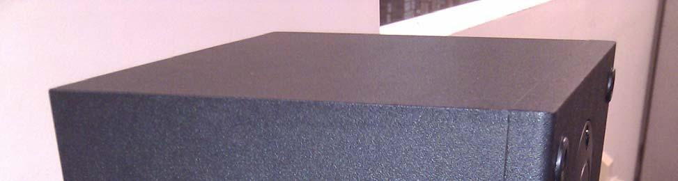
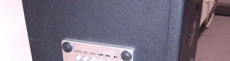
2 Mark a center-line on the side of the cabinet where you plan to install the MP3 player module ( ) and DTA-2's volume control ( ). The DC power jack ( ), and optional 3.5 mm stereo input jack ( ) should be rear mounted, and the easiest place is on the speaker terminal cup. We chose to install the MP3 module and volume control on the left side of the right master speaker cabinet so that we could still use its remote control and easily adjust volume while sitting at the desk where we planned to use them. The power jack and optional 3.5 mm stereo input jack are mounted on the rear to keep the master speaker from looking too cluttered on the side. After marking where the items will reside on the master speaker, cut a 2-1/2" wide by 1-1/4" rectangular hole for the MP3 module. Pay close attention to the dimensions listed for the module so that the four mounting screws have enough material to hold the module in place after cutting out the hole. About an inch below the MP3 module, we drilled a 5/16" through hole and a 1/2" recess hole for the mounting of the volume control included with the DTA-2. The recess hole allows you to adjust how far the volume control protrudes from the cabinet. We made our recess hole on the outside of the cabinet (for ease of drilling), pressing the volume control's mounting nut into place. In order to make the volume control completely level with regards to the cabinet surface, a few washers were used to make the back surface (on the inside of the cabinet) level with the metal finger that would otherwise hold the volume control in place when used with a molded plastic cabinet. Once tightened in place, connect the ribbon cable that will later feed to the DTA-2. Next, drill the holes for the 3.5 mm audio input (optional) and the 2.1 mm power jack, which are 7/32" and 5/16" respectively. We chose to place these on the rear of the cabinet spanning the speaker input terminals on the vertical axis of the terminal cup. The reason for using the speaker terminal cup was that the material thickness facilitated easy mounting. The hardest part of this project is the wiring. That's not to say that it's too tough, it just takes some time, planning, and a careful touch. The first part we began wiring was the MP3 module. At the time we were working without the included harnesses, so this should be easier for you. For all of the connections on the MP3 module, we used 18 AWG Belkin speaker wire and marked which wire went where using different color Sharpie brand markers. In order to make future work with each electronic component easier, each wire run was about 12" longer than it had to be for performing all work outside of the speaker enclosure. See the image below for reference:

3 The +5 VDC and ground wires were soldered to the bottom of the MP3 module at the solder points that feed to the pins above. The left and right wires were soldered to the bottom of the board, but due to close proximity, the ground wire was soldered directly to the adjacent pin on the top of the board. Once the solder cooled, we wrapped the board with a cable tie to hold the wires firmly in place. This is a safety measure and is optional. The MP3 module was then installed using #8 x 1/2" self-tapping truss head screws (which are a little on the large side with regards to the hole diameter), was what we had on hand. Substitute with any screw that suits your taste and needs. #6 fits the screwhole diameter properly. Prior to installing the 3.5 mm jack (centered above the speaker terminals), cut and separate the eight wires within the Belkin Cat5 cable removing them from the cable assembly. These will serve as the conductors for the audio input jack. Cat5 cable conductors were chosen for their flexibility, and feed into the through holes on the 3.5 mm jack perfectly for soldering. We soldered a solid blue conductor to the center tab of the jack for ground, a white striped wire to the small silver tab for the left positive, and a solid orange on the small gold tab for right positive. Again, 12" of extra wire was added to each conductor to facilitate ease of future installation and wiring. When connected to a patch cable, the wiring follows the tip (L+), ring (R+), sleeve (ground) convention. Install the jack into the speaker terminal cup and once you are satisfied with its position (the inner ring abutting the patch plug should be flush with terminal cup) use epoxy to hold it in place. After five minutes we tested the jack to make sure it would stay in place while testing continuity between the opposite end patch plug and the internal wiring. Next, solder the DC power jack with the 18 AWG Belkin speaker wire observing polarity. With this particular jack, there are two ground tabs; one centered, and one on the right with tabs in the 9, 12, and 3 o'clock position. The left tab is your +12 VDC. Once soldered, be sure to cover your connections using heat shrink.

4 Install the DC power plug into place on the terminal cup, centered and below the speaker terminals. There is an angle to the lower section, so make sure you have your hole drilled as low as the cup allows. Once installed, use a small amount of epoxy to hold it in place. After the epoxy dries, connect the 12 VDC power supply listed on the parts list and check for proper voltage and polarity. Up to 12.5 VDC is perfectly fine when not under load. The MP3 module requires 5 VDC power, and if you would like to use the USB port for charging a smart phone (in addition to reading MP3 files) it is highly recommended to use a voltage regulator in conjunction with the 12 VDC power supply. We chose a 7805 IC for the voltage regulator due to the wide operating input voltage (in case something was to go wrong with the power supply). We have listed a regulated power supply in the parts list, so we are operating safely with two regulated voltages. The three pins on the 7805 are (from the left): 1 for voltage (+) in, 2 for shared ground (-), and 3 for voltage (+) out. See the image below for reference: Feed the +12 wire from the 2.1 mm DC input jack to pin 1 of the Additionally, cut a section of positive conductor from the speaker cable to create the +12 for the DTA-2 power input. Strip away about 3/8" from the end of the wire from the jack and 3/8" from each end of the second positive conductor. Solder the two separate cables together and place about and 1-1/2" piece of heatshrink over the pair. Solder this pair to pin 1, placing the heatshrink over the assembly butting against the chip section of the 7805 and shrink into place. Solder the +5 VDC wire from the 7805 IC to the +5 VDC on the MP3 module (make sure you place a piece of heatshrink over one of the wires) and then heatshrink to insulate the joint. Do this also with one of the ground wires from the 7805 to the ground wire of the MP3 module. At this time you can mount the voltage regulator onto a small copper covered coin (drill a hole through this coin; it is to be used as a heatsink) and secure inside the speaker cabinet using a 4-40 pan head screw no more than 1/2" long. Keep in consideration that the second +12 VDC wire from the 7805 and second ground wire still need to be connected to the DTA-2. See the image below for reference.

5 DTA-2 connection locations: (A) Left speaker output (B) Right speaker output (C) Power input (D) Optional LED connection First, solder a pair of speaker wires onto the + and terminals for A; repeat for B. Separate red and black wires are included with the DTA-2 kit. Use these for the power connection at C. Two ferrite cores are included with the kit, as well as two output nonpolarized capacitors. Loop each pair of speaker wires coming from the DTA-2 through and around its ferrite core and set to the side. Slide a piece of heatshrink over, connect, and solder together the +12 VDC and ground wires, from both the 7805 and DTA-2, together; heatshrink the joints for insulation. Next cover (with heatshrink), connect, and solder together the right speaker output negative (from the DTA-2) to both of the black terminated speaker wires that were removed from the speaker terminals at the beginning of the project, and one lead of the output capacitor. Cover (with heatshrink), connect, and solder together the positive right speaker output (from the DTA-2), white terminated speaker wire (for the woofer), a lead from the capacitor removed from the terminal cup, and the other lead of the output capacitor included with the DTA-2. Cover (with heatshrink) and solder together the other lead of the capacitor from the terminal cup to the red terminated speaker wire (for the tweeter). Solder the left DTA-2 speaker outputs to the internal speaker terminals, red to the left for positive and black to the right for negative. The output capacitor is then soldered in parallel between these terminals. Connect the ribbon cable from the volume control to the DTA-2, and locate a free, noninterfering location within the cabinet to epoxy or hot glue the DTA-2 board to. Epoxy and position the DTA-2 in place. We chose the area directly behind the woofer since it will sweep air across this position (which vents through small gaps on the MP3 module).
 and then to a 3.")
6 The gaps on the MP3 module slightly affect bass performance, but it's not enough of an issue to seal the entire unit up. We now need to feed the audio signal connections from both the 3.5 mm jack and MP3 module to the DTA-2. Due to the number of connections, we found it easiest to solder the audio signal connections together (left + to left +...etc.) and then to a 3.5 mm stereo plug, observing the image below: Once you have this internal patch cable is finished, connect it to the DTA-2 and epoxy (or hot glue) into place. After the epoxy dries, lay the cabinet on its side and temporarily connect the woofer and tweeter to their respective wires. Now it's time for testing. Connect the left slave speaker terminals to the master speaker's external speaker terminals. Connect the 12 VDC power supply to the 2.1 DC jack. Right away, the green LED on the MP3 module should illuminate. Save a few MP3 files into the root directory of a USB memory stick or SD card. Connect the storage device to the MP3 module, after a few moments the module should find the MP3 files and start to play automatically; the green LED will flash when playing songs. If not, press the USB/SD button on the module, then play. Once you have a flashing LED, turn the amplifier on with the volume control and adjust to a reasonable level. While playing an MP3 file, connect an external audio device to the 3.5 mm stereo input. As soon as a signal is seen over this connection by the amplifier, the amplifier should auto switch to external signal. You should notice that you are able to get a higher volume using an external device, this is normal. Remove the external device from the 3.5 mm stereo input. The amplifier will switch back to the MP3 player automatically. After verifying everything above works, reinstall the stuffing and install the speakers. Congratulations, you're finished! For portability, we do offer an 8 AA cell battery holder ( ) that can be used to power this system with the addition of a 2.1 x 5.5 DC power plug ( ) wired center positive. Additionally, you could use a cigarette lighter adapter ( ) with a 2.1 x 5.5 DC power plug.
7 Side
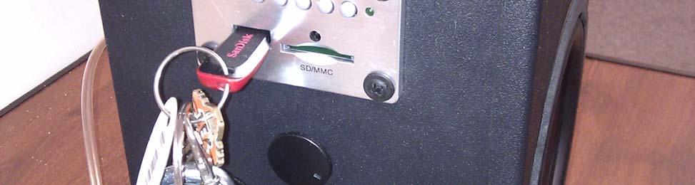
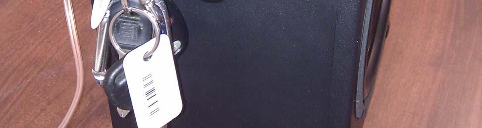
8 Rear


9
BuffaloLabs WiFi Lantern Assembly guide version 1
 BuffaloLabs WiFi Lantern Assembly guide version 1 Needed equipment: Solder iron Solder wire Cutter Wire stripper (optional) Hot glue gun Overview of the components (not including USB cable and box panels)
SDR Cube Transceiver Online Assembly Guide
 Page 1 of 13 SDR Cube Transceiver Online Assembly Guide Detailed construction notes for building and testing the SDR Cube Kit Home Bill of Materials I/O Board Controls Board DSP Board Softrock SR-Base
Button Code Kit. Assembly Instructions and User Guide. Single Button Code Entry System
 Button Code Kit Single Button Code Entry System Assembly Instructions and User Guide Rev 1.0 December 2009 www.alan-parekh.com Copyright 2009 Alan Electronic Projects Inc. 1. Introduction... 4 1.1 Concept
EQ573 Assembly guide. EQ573 Assembly guide Main board 1. Diodes. 2. Resistors (1) 3. Test pins. 4. Ceramic capacitors.
 3. Test pins. 4. Ceramic capacitors.") EQ573 Assembly guide Safety warning The kits are main powered and use potentially lethal voltages. Under no circumstance should someone undertake the realisation of a kit unless he has full knowledge about
EQ573 Assembly guide Safety warning The kits are main powered and use potentially lethal voltages. Under no circumstance should someone undertake the realisation of a kit unless he has full knowledge about
Single cable kit for the FCB1010
 Single cable kit for the FCB1010 1. What is it? With this kit, you can turn your FCB1010 into a phantom powered floorboard, which can do 2-way MIDI communication over one single cable. After installing
Advanced Strobe 1.0 Kit
 Kit Instruction Manual Eastern Voltage Research, LLC December 2013, Rev 1 1 http://www.easternvoltageresearch.com Kit Introduction to the Kit Thank you for purchasing the Kit. If you are looking for a
Upgrading the Mark5 motherboard to the SE7520BD2 Server Board
 Upgrading the Mark5 motherboard to the SE7520BD2 Server Board Joint Institute for VLBI in Europe Martin Leeuwinga (leeuwinga@jive.nl) February 2008 1. Introduction This document describes how to upgrade
Seeburg JCU-DEC Kit Convert Your Seeburg DEC Wallbox Into a Jukebox
 Seeburg JCU-DEC Kit Convert Your Seeburg DEC Wallbox Into a Jukebox MP3 Compact Flash Player Coin Operated or Free Play Integrated Power Amplifier Line-Out to External Amplifier Programmable Autoplay IR
High Power (15W + 15W) Stereo Amplifier
 Stereo Amplifier") High Power (15W + 15W) Stereo Amplifier Build Instructions Issue 1.0 Build Instructions Before you put any components in the board or pick up the soldering iron, just take a look at the Printed Circuit
High Power (15W + 15W) Stereo Amplifier Build Instructions Issue 1.0 Build Instructions Before you put any components in the board or pick up the soldering iron, just take a look at the Printed Circuit
Connecting igaging DigiMAG Scales to the Caliper2PC Interface A step by step Guide
 What is an igaging DigiMAG Scale? The igaging DigiMAG are digital linear scales that are easily connectable to the Caliper2PC interface. They consist of two parts, the encoder and the readout unit. The
Supplemental guide on Camera Fabrication
 Supplemental guide on Camera Fabrication This document describes the steps for fabricating your camera and lighting system. 1 Materials needed Gather all your materials. You will need the small lexan sheet
SM010, Assembly Manual PCB Version 1.0
 180 SM010, Assembly Manual MATRIXARCHATE 16 8 IO SEQUENTIAL MATRIX SIGNAL ROUTER SM010 1 2 1 2 3 4 5 3 4 5 6 7 8 9 10 11 12 6 7 8 9 10 11 12 13 14 15 16 PROGRAM A B C D E F G H f1 f2 20.000 180 SSSR Labs
OpenSprinkler v2.1u Build Instructions
 OpenSprinkler v2.1u Build Instructions (Note: all images below are 'clickable', in order for you to see the full-resolution details. ) Part 0: Parts Check Part 1: Soldering Part 2: Testing Part 3: Enclosure
OpenSprinkler v2.2u Build Instructions
 OpenSprinkler v2.2u Build Instructions (Note: all images below are 'clickable', in order for you to see the full-resolution details. ) Part 0: Parts Check Part 1: Soldering Part 2: Testing Part 3: Enclosure
Insert the male, 90 angled, 2x10 connectors into the corresponding 2x10 sockets and put them in place, flat under the PCB. Solder.
 MC624 Assembly guide Safety warning The kits are main powered and use potentially lethal voltages. Under no circumstance should someone undertake the realisation of a kit unless he has full knowledge about
Gospeed.Racer Hub Assembly for the Asus EEEpc
 Gospeed.Racer Hub Assembly for the Asus EEEpc Before you begin: Please understand that these harnesses are all tested one at a time before I ship them. By installing this harness, you agree to assume any
Constructing a Low-Cost Mobile Eye Tracker
 ==== Constructing a Low-Cost Mobile Eye Tracker ==== Section 1: Introduction This is a detailed set of instructions on how to build a low-cost mobile eye-tracking system from off-the-shelf components.
KAA Watt x 2 Class-D Audio Amplifier Kit
 KAA10021 50 Watt x 2 Class-D Audio Amplifier Kit This amplifier kit uses Texas Instruments TPA3116D2 stereo audio amplifier IC for driving speakers up to 50 watts @ 4 ohm per channel in stereo mode and
Universal Keying Adapter 3+
 Universal Keying Adapter 3+ The Universal Keying Adapter Version 3+ kit will allow you to key nearly any transmitter or transceiver with a straight key, electronic keyer, computer serial or parallel port
CONSOLE CONNECTOR KIT 9501 INSTALLATION INSTRUCTIONS
 CONSOLE CONNECTOR KIT 9501 INSTALLATION INSTRUCTIONS FOR USE WITH: HAMMOND Organ Models L-100, M-100 Series, M-l, M-2, M-3 LESLIE Speaker Models 760, 770, 825 KIT CONTENT Console Connector Assembly 043075
USBCNC USB Disk Key reader for CNC Controls Machine Mount instructions
 USBCNC USB Disk Key reader for CNC Controls Machine Mount instructions 2008-2015 Calmotion LLC, All rights reserved Calmotion LLC 21720 Marilla St. Chatsworth, CA 91311 www.calmotion.com Introduction This
SharpSky Focuser Construction. SharpSky Focuser. Construction Document V st December 2012 Dave Trewren 1
 SharpSky Focuser Construction Document V0.12 1st December 2012 Dave Trewren 1 Contents 1 General... 3 1.1 Change Record... 3 1.2 References... 3 2 Introduction... 5 3 SharpSky driver installation... 5
Part 2: Building the Controller Board
 v3.01, June 2018 1 Part 2: Building the Controller Board Congratulations for making it this far! The controller board uses smaller components than the wing boards, which believe it or not, means that everything
Elecraft K3 KPA3 Power Connector Replacement Revision B, June 30, 2017 Copyright 2017, Elecraft, Inc. All Rights Reserved
 Introduction Elecraft K3 KPA3 Power Connector Replacement Revision B, June 30, 2017 Copyright 2017, Elecraft, Inc. All Rights Reserved The connectors furnishing high current to the KPA3 module have failed
Advanced Lantern 1.0 Kit. Introduction to the Advanced Lantern 1.0 Kit
 Advanced LED Lantern 1.0 Instruction Manual Eastern Voltage Research, LLC Introduction to the Advanced Lantern 1.0 Kit Thank you for purchasing the Advanced Lantern 1.0 Kit. This kit is an advanced microprocessor
Installing a Power over Ethernet injector
 Installing a Power over Ethernet injector AlphaEclipse StreetSmart and RoadStar signs The instructions in this document explain how to install/replace a Power over Ethernet (PoE) injector in a StreetSmart
MP3 audio amplifier. Build Instructions. Issue 2.0
 MP3 audio amplifier Build Instructions Issue 2.0 Build Instructions Before you put any components in the board or pick up the soldering iron, just take a look at the Printed Circuit Board (PCB). The components
RSL PSM-2 Power Supply Module Project: Modifying a FlatCap2
 RSL PSM-2 Power Supply Module Project: Modifying a FlatCap2 Dear Do-It-Yourselfer, The stock FlatCap2 is less than a stellar performer. Used with a CD5 CD player, for example, it gives flabby bass control,
VG-305A AC Traffic Light Controller Kit
 Galak Electronics Electronic kits and components Website: GalakElectronics.com Email: sales@galakelectronics.com Phone: (302) 832-1978 VG-305A AC Traffic Light Controller Kit Thank you for your purchase
Patch Bay. Model 9746 Assembly and Using Manual PAiA Corporation
 Patch Bay Model 9746 Assembly and Using Manual This second-generation 9700-series processing element for modular sound synthesizers is designed to provide great sound and excellent value. A two-section
Assembly Guide. LEDs. With these assembly instructions, you can easily build your own SWT16. All required components are included in this kit.
 Assembly Guide With these assembly instructions, you can easily build your own SWT16. All required components are included in this kit. You need the following tools: soldering iron, wire cutter and solder.
[Note: Power adapter is not included in the kits. Users need to prepare a 9 12 V ( >300mA capacity ) DC power supply]
![[Note: Power adapter is not included in the kits. Users need to prepare a 9 12 V ( >300mA capacity ) DC power supply]](/thumbs/76/74094055.jpg "[Note: Power adapter is not included in the kits. Users need to prepare a 9 12 V ( >300mA capacity ) DC power supply]") 062 LCD Oscilloscope Assembly Notes Applicable Models: 06203KP, 06204KP DN062-18v02 Important Notes 1. Some components shown in the schematic and PCB layout are for options or adjustments. They do not
062 LCD Oscilloscope Assembly Notes Applicable Models: 06203KP, 06204KP DN062-18v02 Important Notes 1. Some components shown in the schematic and PCB layout are for options or adjustments. They do not
How to build an Olympus D-360L Trail Camera using the PixController Universal "Digital Trail Camera Kit" w/ RS-232-U PIC Chip
 Copyright, PixController, Inc. http://www.pixcontroller.com, all rights reserved. How to build an Olympus D-360L Trail Camera using the PixController Universal "Digital Trail Camera Kit" w/ RS-232-U PIC
Assembly of the TACOS WAT-910BD Housing v2
 1) Circuit Diagram 2) Assembly of PCB a)tools Required. Only simple hand tools are necessary to complete the assembly of the PCB. - Soldering Iron and solder - Needle nose pliers - Wire clippers/trimmers
RC Tractor Guy Controller V2.1 Assembly Guide
 RC Tractor Guy Controller V. Assembly Guide Features 0 Push button inputs Dual axis thumb sticks with built-in push button Rotary encoders with built-in push button MCU Socket to suit Meduino Mega 560
DELUXE STEREO AMPLIFIER KIT
 ESSENTIAL INFORMATION BUILD INSTRUCTIONS CHECKING YOUR PCB & FAULT-FINDING MECHANICAL DETAILS HOW THE KIT WORKS CREATE YOUR OWN SPEAKER DOCK WITH THIS DELUXE STEREO AMPLIFIER KIT Version 2.0 Build Instructions
Revised: Page 1
 Brought To You By And Designed By: Revised: 2017-05-07 Page 1 Features Of The Universal PSU Kit: Fits all standard Apple II and /// Power Supply Enclosures. (all parts included, user supplies household
Teensy 3.5/3.6 Breakout (Revision A, Standard)
") Teensy 3.5/3.6 Breakout (Revision A, Standard) This is a breakout for the Teensy 3.5 and Teensy 3.6 development boards by PJRC. Included are all the pin headers you need to assemble it, a switch to select
Teensy 3.5/3.6 Breakout (Revision A, Standard) This is a breakout for the Teensy 3.5 and Teensy 3.6 development boards by PJRC. Included are all the pin headers you need to assemble it, a switch to select
QRPGuys Single Lever Keyer/Paddle
 QRPGuys Single Lever Keyer/Paddle First, familiarize yourself with the parts and check for all the components. If a part is missing, please contact us and we will send one. You must use qrpguys.parts@gmail.com
Digital Candle 1.0 Kit
 Kit Instruction Manual Eastern Voltage Research, LLC June 2012, Rev 1 1 http://www.easternvoltageresearch.com Introduction to the Kit Thank you for purchasing the Kit. This kit is definitely a favorite
Digital Flame 1.0 Kit
 Digital Flame 1.0 Kit Instruction Manual Eastern Voltage Research, LLC June 2012, Rev 1 1 http://www.easternvoltageresearch.com Introduction to the Digital Flame 1.0 Kit Thank you for purchasing the Digital
Reflowing Xbox 360 Motherboard
 Reflowing Xbox 360 Motherboard Reflow the solder on your Xbox 360's motherboard. Written By: Andrew Bookholt ifixit CC BY-NC-SA www.ifixit.com Page 1 of 31 INTRODUCTION Use this guide to reflow the solder
CONEC Industrial Ethernet Circular Sealed RJ45 Connector System consists of a RJ45 Plug Kit, a Receptacle Kit and a Protective Cover Assembly.
 Revised Sept-28-2009 Sealed Industrial Ethernet Circular IP67 Cat. 5e RJ45 Connector System Instructions CONEC Industrial Ethernet Circular Sealed RJ45 Connector System consists of a RJ45 Plug Kit, a Kit
LED Sequencer 1.0 / 1.5
 LED Sequencer 1.0 / 1.5 Instruction Manual Eastern Voltage Research, LLC May 2012, Rev 2 1 http://www.easternvoltageresearch.com Introduction to the LED Sequencer 1.0 Thank you for purchasing the LED Sequencer
HARDWARE OPERATIONS MANUAL
 HARDWARE OPERATIONS MANUAL Table of Contents INTRODUCTION... 2 SECTION 1: HARDWARE COMPONENT ASSEMBLIES... 2 MECHANICAL HARDWARE AND CASE... 2 PCB ASSEMBLY... 4 ISD RECORDING CIRCUIT... 5 BREADBOARD ASSEMBLY...
QUASAR ELECTRONICS KIT No Hi-Fi PREAMPLIFIER WITH REMOTE CONTROL
 QUASAR ELECTRONICS KIT No. 1070 Hi-Fi PREAMPLIFIER WITH REMOTE CONTROL General Description This is a hi-fi STEREO preamplifier based on a single integrated circuit which employs a revolutionary new method
IQ32 Upgrade Kit Assembly Instructions
 IQ32 Upgrade Kit Assembly Instructions Jim Veatch WA2EUJ September 17, 2018 TABLE OF CONTENTS 1. INTRODUCTION... 3 2. IQ-32 UPGRADE KIT INVENTORY... 4 3. PREPARING THE RS-HFIQ AND SIDE PANELS... 6 4. CONNECTING
The DIG-CXXXX Installation and User s Manual
 The DIG-CXXXX Installation and User s Manual Table of Contents Last Updated: August 23, 2002 READ THIS FIRST!!!... 1 Introduction to the Installation Process:... 2 Connecting to the Player Circuit Board...
TECHKNOW, INC. Kiosk Order Confirmation System INSTALLATION MANUAL. Revision Date: July 11, 2012 Part # Version 3.2
 document Page 1 of 18 TECHKNOW, INC Kiosk Order Confirmation System INSTALLATION MANUAL Revision Date: July 11, 2012 Part # Version 3.2 Techknow, Inc. 393 Mayfield Road Duncan, SC 29334 www.gotechknow.com
Written By: Ben Eisenman
 iphone 3GS Rear Panel Replacement Replace a broken rear case on your iphone 3GS. Written By: Ben Eisenman ifixit CC BY-NC-SA www.ifixit.com Page 1 of 22 INTRODUCTION The plastic rear half of the iphone.
Obtained from Omarshauntedtrail.com
 Getting Started Boombox Amplifier http://www.deathlord.net/boomboxamp/boom.htm BoomBox AmplifiER Difficulty Rating: For years I imagined that my old, broken boom boxes I had laying around could be used
Installation Notes TII Model 341 Protector
 Installation Notes TII Model 341 Protector (ATT-IS PEC 32918) for MERLIN Communications System In Range Out of Building (IROB) Station Installation By Trained Technician Only WARNING: Failure to follow
The Radio Control Temperature Logger (RCTL) Manual For hardware version 1.0 Manual version 1.0b
 Manual For hardware version 1.0 Manual version 1.0b") The Radio Control Temperature Logger (RCTL) Manual For hardware version 1.0 Manual version 1.0b All materials owned by Dan Gebhardt Introduction This device records the temperature of a model engine during
The Radio Control Temperature Logger (RCTL) Manual For hardware version 1.0 Manual version 1.0b All materials owned by Dan Gebhardt Introduction This device records the temperature of a model engine during
ARRL ETP Solder Hour Clock Kit Construction Manual
 ARRL ETP Solder 101 24-Hour Clock Kit Construction Manual Do a complete parts check cross checking the individual parts against the parts list. Pay particular attention to the color code for the resistors:
imac Intel 27" Retina 5K Display CPU Replacement
 imac Intel 27" Retina 5K Display CPU Replacement Replace or upgrade the CPU in your imac Intel 27" Retina 5K Display. Written By: Sam Lionheart ifixit CC BY-NC-SA www.ifixit.com Page 1 of 36 INTRODUCTION
A Backlighted LCD for your K1
 A Backlighted LCD for your K1 (K1BKLTKIT) Tom Hammond - NØSS, July 27, 2006 Rev C Thanks to Wayne Burdick, N6KR for suggesting this implementation of backlighting the K1 display. APPLICABILITY This modification
Megatouch FORCE Monitor Chassis Board Replacement
 Megatouch FORCE Monitor Chassis Board Replacement Visit the Merit Industries, Inc. Web site http://www.meritind.com merit industries, inc. PM0337-01 Rev C Table of Contents FORCE Classic Monitor Chassis
REMOTE HEAD ADAPTER INSTALLATION GUIDE
 REMOTE HEAD ADAPTER INSTALLATION GUIDE The Remote Head adapter is a valuable accessory for the Uniden BC-780, 785 and 796 scanners. It allows the scanner's control panel to be removed from the radio and
Make Kits and Casemods
 Make Kits and Casemods This weekend, you ll learn how to make a Minty Boost usb charger and a Daisy mp3 player. After you put these together you can put them into customized cases. I made my charger fit
ipad Mini Wi-Fi Front Facing Camera Replacement
 ipad Mini Wi-Fi Front Facing Camera Replacement Replace the Front Facing Camera in your ipad Mini Wi-Fi. Written By: Andrew Optimus Goldberg ifixit CC BY-NC-SA www.ifixit.com Page 1 of 42 INTRODUCTION
Alesis MMT8 16x Memory Expansion Modification (Black model MMT8 s) Equipment. Components required. Other bits:
 Equipment. Components required. Other bits:") Alesis MMT8 16x Memory Expansion Modification (Black model MMT8 s) by Graham Meredith, 006 Revised 15 th January 009 gmeredith1@yahoo.com.au This modification expands the memory of the Alesis MMT8 to 16x
Alesis MMT8 16x Memory Expansion Modification (Black model MMT8 s) by Graham Meredith, 006 Revised 15 th January 009 gmeredith1@yahoo.com.au This modification expands the memory of the Alesis MMT8 to 16x
Custom O2+ODAC Soldering Instructions
 Custom O2+ODAC Soldering Instructions Preparations The following components should be omitted during basic assembly: R1, R2 D2, D6 BT2 The following components should be omitted based on required customization:
dual bipolar voltage controlled step sequencer DIY ASSEMBLY MANUAL v1.03
 dual bipolar voltage controlled step sequencer DIY ASSEMBLY MANUAL v1.03 Contents Contents... 2 Introduction... 3 Part Sourcing Notes for Non Kit Builders... 3 Eurorack Kit Assembly... 4 Resistors and
January Bob Wright. 1 P age Bob Wright
 The upgrade is completed using the 401 control board and three Step1 driver boards supplied as a kit by Conqueror Design and Engineering Ltd. The kit includes all cable terminators for connections to the
Mini B lue M idnight
 Mini Blue Midnight 2011 by Shattered Glass Audio. All rights reserved. No part of this document may be reproduced or transmitted in any form or by any means, electronic, mechanical, photocopying, recording,
Installation Manual. Balboa Bluetooth Audio bba 2
 Installation Manual Balboa Bluetooth Audio bba 2 WARNING There are no user serviceable parts inside the system pack. All connections must be made by a qualified electrician in accordance with the country
Installing PRO/DGX or Pro Soloist MIDI interface. R Grieb 9/08/2017
 Installing PRO/DGX or Pro Soloist MIDI interface. R Grieb 9/08/2017 Please read these instructions before purchasing the MIDI interface, to make sure you are comfortable performing the necessary steps.
AB-2D AB-2D SPEAKER A,B OR A+B SELECTOR INSTALLATION & OPERATION GUIDE
 M O D E L AB-2D AB-2D SPEAKER A,B OR A+B SELECTOR INSTALLATION & OPERATION GUIDE AB-2D Speaker/Amplifier Selector TABLE OF CONTENTS Introduction 1 Features and Benefits 1 Installation Considerations 3
Assembly Instructions IV-11 DCF, melody
 This IV-11 clock is the next generation to the IV-11 Quartz, DCF, melody. This is not a beginner kit. It requires soldering experience on the IV-18 and the IV-3A board The switching power supply wall adapter
CP5176 Assembly guide. Soldering. CP5176 Assembly guide Main PCB PCB split. Document revision 2.1 Last modification : 12/11/17
 CP5176 Assembly guide Safety warning The kits are main powered and use potentially lethal voltages. Under no circumstance should someone undertake the realisation of a kit unless he has full knowledge
Written By: Sam Lionheart
 iphone 5s Lightning Connector Replacement Remove the Lightning connector/headphone jack assembly from your iphone 5s. Written By: Sam Lionheart ifixit CC BY-NC-SA www.ifixit.com Page 1 of 26 INTRODUCTION
Replacing the Power Supply
 APPENDIX B This appendix includes information on how to replace the power supply for the Cisco AS550XM universal gateway and contains the following sections: Safety Recommendations, page B-1 Required Tools
527F CNC. Retrofit controller for machines made by Fadal Machining Centers. Installation and set-up manual Calmotion LLC
 527F CNC Retrofit controller for machines made by Fadal Machining Centers Installation and set-up manual 2008-2018 Calmotion LLC Calmotion LLC 7536 San Fernando Road Sun Valley, CA 91352 www.calmotion.com
Plasma Panel Replacement Guide DU-42PX12X
 Plasma Panel Replacement Guide DU-42PX12X Panel Replacement: At this point, the panel has been determined to be defective and replacement is necessary. Upon receiving the replacement panel, it must be
Assembling the Cassette Audio Digitization System from the Indigitization Project
 Assembling the Cassette Audio Digitization System from the Indigitization Project Tools Required: Box Cutter Phillips screwdriver Pen Scissors Label Maker Supplies Required: Screws for rack case (included
LANCNC FTP Data Server for CNC Controls Machine Mount instructions
 LANCNC FTP Data Server for CNC Controls Machine Mount instructions 2008-2016 Calmotion LLC, All rights reserved Calmotion LLC 21720 Marilla Street Chatsworth, CA 91311 www.calmotion.com Introduction This
Tubbutec Sumtiple Kit Version Construction Manual
 Tubbutec Sumtiple Kit Version Construction Manual This document describes the construction of the Sumtiple Kit. The following parts are included: 1x Sumtiple PCB with SMD-Parts already soldered 1x Front
Casio CZ. Non volatile memory modification Installation instructions version copyright 2013 Artefacts
 Casio CZ Non volatile memory modification Installation instructions version 2.0 2017 www.artefacts.nl copyright 2013 Artefacts Introduction The Casio CZ-101 and CZ-1000 do not have a separate backup battery
solutions for teaching and learning
 RKAmp1 Component List and Instructions PCB layout Constructed PCB Schematic RKAmp1 Stereo Amplifier Page 1 Description The RKAmp1 stereo amplifier PCB has been designed around the 2 x 1watt stereo amplifier
TKEY-1. CW touch key. (no electromechanical contacts) Assembly manual. Last update: June 20,
 Assembly manual. Last update: June 20,") TKEY-1 CW touch key (no electromechanical contacts) Assembly manual Last update: June 20, 2017 ea3gcy@gmail.com Updates and news at: www.ea3gcy.com Thanks for constructing the TKEY-1A CW touch key Have
TKEY-1 CW touch key (no electromechanical contacts) Assembly manual Last update: June 20, 2017 ea3gcy@gmail.com Updates and news at: www.ea3gcy.com Thanks for constructing the TKEY-1A CW touch key Have
Quicksilver 606 TR-606 CPU Upgrade
 Quicksilver 606 TR-606 CPU Upgrade D650C 128 Installation Guide Social Entropy Electronic Music Instruments TABLE OF CONTENTS WARNINGS... 1 OVERVIEW... 2 WHAT'S IN THE BOX... 3 OPENING THE TR-606 CASE...
Apex Tablet 7 Battery Replacement
 Apex Tablet 7 Battery Replacement This guide will instruct you on how to replace the lithium-ion battery inside the Apex 7" Tablet. Written By: Corrine Nief ifixit CC BY-NC-SA www.ifixit.com Page 1 of
A-dec 570L Dental Light on a DCS System INSTALLATION GUIDE
 A-dec 570L Dental Light on a DCS System INSTALLATION GUIDE C ONTENTS Choose an Installation Guide...... Before You Begin.............. 3 Disconnect the Light Cable........ 3 Cut the Light Cable............
Zero2Go. User Manual (revision 1.03) Wide Input Range Power Supply for Your Raspberry Pi. Copyright 2017 UUGear s.r.o. All rights reserved.
 Wide Input Range Power Supply for Your Raspberry Pi. Copyright 2017 UUGear s.r.o. All rights reserved.") Zero2Go Wide Input Range Power Supply for Your Raspberry Pi User Manual (revision 1.03) Copyright 2017 UUGear s.r.o. All rights reserved. Table of Content Product Overview... 1 Product Details... 3 Package
Zero2Go Wide Input Range Power Supply for Your Raspberry Pi User Manual (revision 1.03) Copyright 2017 UUGear s.r.o. All rights reserved. Table of Content Product Overview... 1 Product Details... 3 Package
Figure 1. The completed programming kit List of Parts
 Many NearSys kits are programmed through a three pin header soldered to the PCB. Since a three pin receptacle is not a common termination for a serial cable, this kit contains the parts to make one. In
QUASAR KIT No DIGITAL DOWN TIMER 99 MIN WITH PIC
 QUASAR KIT No 1173 - DIGITAL DOWN TIMER 99 MIN WITH PIC KIT 1173 is a digital countdown timer based on a micro controller, thus securing reliability and excellent operation under any circumstances. It
Onwards and Upwards, Your near space guide. Figure 1. CheapBot Line Follower
 The CheapBot Line Follower is a plug-in single-board sensor for almost any programmable robot brain. With it, a robot can detect the presence of a black or white zone beneath its two sensors. In its simplest
Sony NEX-7 Screen Replacement
 Sony NEX-7 Screen Replacement If your camera's screen is broken or non functioning, this guide will show you how you can replace the screen. Written By: Jay Miley ifixit CC BY-NC-SA www.ifixit.com Page
Written By: Sam Lionheart
 iphone 5s Earpiece Speaker Replacement Replace the earpiece speaker in an iphone 5s. Written By: Sam Lionheart ifixit CC BY-NC-SA www.ifixit.com Page 1 of 22 INTRODUCTION Use this guide to replace a broken
Chapter 2 Working Inside Desktop Computers and Laptops
 Chapter 2 Working Inside Desktop Computers and Laptops TRUEFALSE 1. When disassembling a computer, it's okay to stack circuit boards on top of each other as long as you follow ESD protection rules. (A)
solutions for teaching and learning
 RKAmp3 Component List and Instructions PCB layout Constructed PCB Schematic RKAmp3 Stereo Amplifier Page 1 Description The RKAmp3 stereo amplifier PCB has been designed around the 2 x 7watt stereo amplifier
When you are ready to build your computer you will have the following materials to work with.
 Copyright 2009 BOSMA Enterprises Chapter 3 Putting the Computer Together When you are ready to build your computer you will have the following materials to work with. 1. One motherboard. 2. One ribbon
ipod Touch 4th Generation 30 Pin Dock Connector Replacement
 ipod Touch 4th Generation 30 Pin Dock Connector Replacement Learn how to replace the 30 pin dock connector on an ipod touch 4th generation. Written By: Gabe Keehn ifixit CC BY-NC-SA www.ifixit.com Page
Nvidia Shield Tablet K1 Micro USB Port Replacement
 Nvidia Shield Tablet K1 Micro USB Port Replacement This is a guide for the removal and replacement of the Micro USB Port. Written By: Ryan Butler ifixit CC BY-NC-SA www.ifixit.com Page 1 of 14 INTRODUCTION
XYLOPHONE KIT ESSENTIAL INFORMATION. Version 2.0 CREATE YOUR OWN ELECTRONIC MUSICAL INTRUMENT WITH THIS
 ESSENTIAL INFORMATION BUILD INSTRUCTIONS CHECKING YOUR PCB & FAULT-FINDING MECHANICAL DETAILS HOW THE KIT WORKS CREATE YOUR OWN ELECTRONIC MUSICAL INTRUMENT WITH THIS XYLOPHONE KIT Version 2.0 Build Instructions
imac Intel 21.5" EMC 2389 Stand Replacement
 imac Intel 21.5" EMC 2389 Stand Replacement Replace a broken or cosmetically unappealing stand on the imac 2389 21.5 Written By: Aaron Cooke ifixit CC BY-NC-SA www.ifixit.com Page 1 of 30 INTRODUCTION
HOW TO ADD TWO USB PORTS TO LINKSYS WRT54GS Ver.1 AND WRT54G Ver.2 ROUTERS OPENING THE CASE
 HOW TO ADD TWO USB PORTS TO LINKSYS WRT54GS Ver.1 AND WRT54G Ver.2 ROUTERS By Danuel Quaintance, AF7EF April 23, 2014 OPENING THE CASE To do this mod requires opening the case of the router. To do so you
INSTRUCTIONS FOR THE INSTALLATION OF THE INFINITY "L" DISPLAY HOOD (INTO PREVIOUSLY INSTALLED INFINITY "L" SYSTEMS)
") Doc. 6001025 Rev B INSTRUCTIONS FOR THE INSTALLATION OF THE INFINITY "L" DISPLAY HOOD (INTO PREVIOUSLY INSTALLED INFINITY "L" SYSTEMS) Rev. B Doc. 6001025 Page 1 of 13 IMPORTANT NOTICE This document covers
Doc. 6001025 Rev B INSTRUCTIONS FOR THE INSTALLATION OF THE INFINITY "L" DISPLAY HOOD (INTO PREVIOUSLY INSTALLED INFINITY "L" SYSTEMS) Rev. B Doc. 6001025 Page 1 of 13 IMPORTANT NOTICE This document covers
UF-3701 Power Board Construction Guide
 Page 1/5 Soldering and Part Placement See the Chapter 3 of the MIT 6270 Manual for information on electronic assembly, including soldering techniques and component mounting. Construction Information All
imac Intel 27" EMC 2639 Hard Drive
 imac Intel 27" EMC 2639 Hard Drive Replacement Replace the Hard Drive in your imac Intel 27" EMC 2639. Written By: Walter Galan ifixit CC BY-NC-SA www.ifixit.com Page 1 of 26 INTRODUCTION Replacing the