vsync912i & 1612i User Guide vsync DVR December 2007 Rev A. December 2007
|
|
|
- Vincent Underwood
- 5 years ago
- Views:
Transcription
1
2 TABLE OF CONTENTS 1. Introduction Overview Summary of the Specifications of VSync912i & 1612i Packing List Product Description Front Panel Rear Panel Remote Controller Alphabet Input with Remote Controller Getting Started Setting Up the DVR Setup Main Screen Setup Live Setup Recording Mode Motion Zone Set Up Record Schedule Setup Device Mode ALARM-OUT PTZ Control SPOT-OUT Setup System Mode Setup Security Mode Setup Network Mode Ports Network Types Setup - Storage Mode Saving Setup Local Viewing Live Window SEARCH Window Play mode PTZ Control
3 5. Archiving Video via USB or CD-RW Capturing images or video Transferring still images or video onto USB or CD-RW Firmware Upgrade Preparing USB memory with upgrade firmware Network Client - Remote Monitoring and Playback Remote Setup Using Embedded Web-Server of vsync912i & 1612i
4 CAUTION THIS PRODUCT HAS MULTIPLE-RATED VOLTAGES (110V AND 220V). MAKE SURE TO SET THE VOLTAGE SELECTION SWITCH AT THE REAR PANEL TO THE PROPER VOLTAGE LEVEL OF YOUR REGION. THIS PRODUCT USES A LITHIUM BATTERY. THERE IS RISK OF EXPLOSION IF THE BATTERY ON THE MAIN BOARD IS INSTALLED INCORRECTLY. DISPOSE OF USED BATTERIES ACCORDING TO INSTRUCTIONS. THIS EQUIPMENT AND ALL COMMUNICATION WIRING IS INTENDED FOR INDOOR USE. TO REDUCE THE RISK OF FIRE OR ELECTRIC SHOCK, DO NOT EXPOSE THE UNIT TO RAIN OR MOISTURE. Rack Mount Instructions A) Elevated Operating Ambience - If installed in a closed or multi-unit rack assembly, the operating ambient temperature of the rack environment may be greater than room ambient. Therefore, consideration should be given to installing the equipment in an environment compatible with the maximum ambient temperature (Tma) specified by the manufacturer. B) Reduced Air Flow - Installation of the equipment in a rack should be such that the amount of air flow required for safe operation of the equipment is not compromised. C) Mechanical Loading - Mounting of the equipment in the rack should be such that a hazardous condition is not achieved due to uneven mechanical loading. D) Circuit Overloading - Consideration should be given to the connection of the equipment to the supply circuit and the effect that overloading of the circuits might have on overcurrent protection and supply wiring. Appropriate consideration of equipment nameplate ratings should be used when addressing this concern. E) Reliable Earthing - Reliable grounding of rack-mounted equipment should be maintained. Particular attention should be given to supply connections other than direct connections to the branch circuit (e.g. use of power strips)." 4


5 CD-RW Installation Guide 1. Open the top cover of vsync DVR set and Install the CD-RW inside the DVR. 2. Fasten the screws on both side of CD-RW as indicated in red circle below. 3. Connect the IDE CD-RW 40pin cable and Power cable to the point on both CD-RW and Main board as indicated in red circles below. Set the CD-RW jumper setting as MASTER Compatible CD-RW model Sony CRX230EE or contact the vsync DVR distributor for other models. 5


6 HDD Installation Guide 1. Mount the bracket to the hard disk using the supplied HDD mounting bracket screws. 2. Connect the supplied IDE HDD 80pin cable and Power cable to the hard disk and mount the hard disk to the unit using the supplied HDD screws. 3. HDD JUMPER SETTING 1 ST HDD = MASTER 2 nd HDD = SLAVE IDE HDD CABLE CONNECTION ORDER BLUE: MAIN BOARD WHITE: SLAVE HDD BLACK: MASTER HDD 6
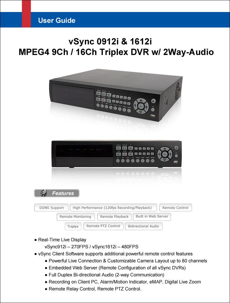
7 1. Introduction 1.1. Overview Triplex MPEG-4 9/16 Channel DVR with Real-Time Live Display and Simultaneous Play Back. vsync912i & 1612i, (vsync912i Nine channel model & vsync1612i Sixteen channel model). vsync912i & 1612i features powerful embedded RTOS (Real Time Operating System). MPEG-4 video codec (video encoder/decoder), delivers uncompromised performance providing high compression plus high quality video images. vsync912i & 1612i increases the days of recording between overwrite periods while improving the quality of video images. Full triplex capability ensures uninterrupted recording. vsync DVR supports simultaneous: 1. Video Recording 2. Live Video Monitoring up to 80 cameras Locally via video outputs. Remotely via vsync network client software and visync Central Monitoring Software. 3. Play Back or File archiving via USB 2.0 port and CD-RW. Or 1. Video Recording 2. Remote Playback via vsync network client software and visync CMS. vsync software also allows the administrator to remotely connect to, monitor, and manage multiple networked DVRs. The vsync software logs the operation, motion, and alarm statuses of sites throughout the day for later analysis. The vsync software lets you search based on time or event, record on a remote PC, and retrieve video clips from remote sites. vsync software supports additional powerful remote control features, Powerful Live Connection & Customizable Camera Layout up to 80 channels, Embedded Web Server (Remote Configuration of all vsync DVRs) Full Duplex Bi-directional Audio (2-way Communication) Recording on Client PC, Alarm/Motion Indicator, emap, Digital Live Zoom Remote Relay Control, Remote PTZ Control. 7
8 NAFS (Network-Attached File Server) file systems provide a cluster-based network-attached file server which offers a high level of performance, reliability, and availability. - Ex. Prevention of data loss and corruption in the event of a power failure. Multiplexing operation. State-of-the-art live monitoring and playback both locally and remotely. Individual channel recording and playback with different frame rates. Hidden Channel Mode on selected channels provides extra privacy and uninterrupted recording. Embedded Web-Viewer provides direct access using IP address or DDNS address in Internet Explorer. Multi-site management via network: up to 80 cameras. - Supported by vsync network client software and visync CMS. - Remote live monitoring & recording, playback, backup, PTZF control & Presets, relay sensor control, emap, Digital Live Zoom, and 2-way communication. - Remote DVR management via embedded Web-Browser for easy adjustments. - Mobile phone & PDA viewing integration. Network via LAN, DDNS, DHCP, ADSL (Dynamic and Static IP addresses). Full duplex 4 Channel G.711 synchronized audio recording and Bi-directional Audio Communication. Built-in Quad Multiplexer provides sequential or quad display on all or selected channels. User-friendly setup menu with simplified G.U.I.(Graphic User Interface). Easy to schedule weekly recording plans. Motion detection Use the 30x24 grid to define motion zones for each camera. Internal Pan/Tilt/Zoom/Focus controller. Easy operation via front panel and optional remote controller. Increased security by user name and password verification. Video loss detection. Backup - Still-images or AVI data onto USB storage device, internal CD-RW, or Network. USB port for JPEG/MPEG data backup and software upgrade using USB storage device. Still image capture and review as JPEG format. Variety of Hard Drive Sizes - up to 1TB internally (500GB HDD X 2) for long-term recording. Multi-Languages - User can easily select language from Setup menu. Various Video Outputs - VGA(800x Bit Color), TV-Out, S-Video, SPOT-Out, Loop-Out. 8
9 1.2. Summary of the Specifications of VSync912i & 1612i Item Description Remarks Operating System RTOS in firmware Video/Audio MPEG-4(video) / G.711-PCM (audio) Compression Triplex Function Record/Playback/Live Streaming or Record/USB archive/live Streaming Video Input Format NTSC/PAL Auto-Detection Video Input 9 Ch (16 Ch) In Video Output 1Ch VGA, 1 Ch BNC (Composite), 1Ch Spot-Out. 9Ch(16Ch) Loop-Out, 1 Ch S-VIDEO Display NTSC Frame Rate Recording Frame Rate 270(480) frames/sec Real-Time 9 Ch(16 Ch) x 30 frames/sec (Hidden Display Function) PAL 225(400)frames/sec 25 frames/sec/ch 120 frames/sec NTSC (Hidden Record Function) 352x240 resolution (Quad) PAL 100 frames/sec 352x288 resolution Recording Frame Rate NTSC 30 frame /sec (total) 704 x 480 resolution (Full) PAL 25 frame /sec (total) 704 x 576 resolution Record Modes Record Quality Resolution Audio Input/Output Channel Alarm In/Alarm Output HDD CD-RW Motion Detection Search Mode Playback Speed Continuous/Motion/Schedule/Sensor/Manual Network/Standard/High/Superior/Ultra NTSC : 704 x 480(1 CH), 352x 240(Quad) PAL : 704 x 576(1 CH), 352 x 288(Quad) Supports CIF, Half D1 & Full D1 4 Ch Input/1 Ch Output 2-way communication(bi-directional) Audio via network 9/16 Alarm Input (NC/NO selectable) / 8 Relay Output 3.5, IDE type9 (IDE ATA133 Type), Min 80GB up to 2 IDE HDDs Optional CD-RW Motion-Triggered Recording Date/Time/Event Search 1x, 2x, 4x, 8x 9
, Firmware upgrade USB 2.")
10 Serial Interface USB Upgrade Method PTZ Control Network Interface Client PC S/W ( vsync ) Remote Playback Power 1 RS-232C (POS text inserter connection) 1 RS-422/485 (for PTZ control) Archiving (still images in JPEG format, video in AVI format), Firmware upgrade USB 2.0 Port or Web-Browser Local & vsync Client Software LAN(10/100Base-T), Static, DHCP, PPPoE, and DDNS Window2000/XP/Vista Live Connection & Customizable Camera Layout up to 80 channels Embedded Web Server (Remote Configuration of all vsync DVRs) Full Duplex Bi-directional Audio (2-way Communication) Recording on Client PC, Alarm/Motion Indicator, emap, Digital Live Zoom Remote Relay Control, Remote PTZ Control Via vsync Client Software 110/220V, 50/60Hz 1.3. Packing List vsync912i or vsync1612i Support CD includes: vsync Network Client, Utility Programs, Manual(s). Infrared Remote Control Vsync.exe Batteries Screws for mounting HDD. (Preinstalled when unit is shipped with HDD) HDD connection cables (2 ea). (Preinstalled when unit is shipped with HDD(s)) 10
11 HDD Mounting Brackets (2ea) (Preinstalled when unit is shipped with HDD(s)) 2. Product Description 2-1. Front Panel Figure 2.1. Front Panel of vsync912i & 1612i 11
12 Name HDD REC ALARM NETWORK POWER Table Indication LEDs Description LED illuminates when system is accessing the hard disk drive. LED illuminates when recording is enabled. LED illuminates when alarm sensor(s) is/are triggered or detects video motion. (Alarm sensor(s) and/or video motion detection must be configured first). LED illuminates when clients connect through vsync software via network port. LED illuminates when the DVR unit is on. Table Buttons on the Front panel Name Description POWER Power ON/OFF. (Prompts for password before shutdown) Configure settings for power down in the SECURITY Setup Menu. The default password is DIS Press to select full, quad, 9 or 16 split-screens in live display mode. SEQ Press to start auto-sequencing in 1 Ch, 4 Ch, 9 Ch, or 16 Ch display modes. AUDIO Press to select audio mode. Disable or Mute all 4 channels or selected channels only. PTZ Press to initiate PTZ control SETUP Press to launch SETUP menu. ALARM Press to silence alarm operation. ARCHIVE Press to review the ARCHIVE LIST in live display mode. CAP/USB Press to take a snapshot, or capture still images (JPEG format), during live or playback modes. REW/LOG (During Playback) Press to rewind video footage at 1x, 2x, 4x, and 8x speeds or to see the LOG LIST in live display mode. F/REW Jump/Step backward. In playback mode, the playback position reverses/jumps backwards 60 seconds. F/ADV Jump/Step forward. In playback mode, the playback position moves forward 60 seconds. FF (From Playback Mode) Pressing fast forward advances footage at 1x, 2x, 4x, and 8x speeds. PLAY/PAUSE From Live Display Mode: Press to enter SEARCH menu. From Playback Mode: Press to play or pause video. REC Press to start or stop manual recording. 12
 Press to scroll right in the menu or to change values in setup mode. (Also used as the number 2 when entering a password.) Press to scroll down in the menu or to change values in setup mode.")
 (Surrounded by the direction control keys) Pressing selects desired menu item or saves setup values in menus.")
13 UP RIGHT DOWN LEFT SEL ESC USB Port Press to scroll up in the menu or to change values in setup mode. (Also used as the number 1 when entering a password.) Press to scroll right in the menu or to change values in setup mode. (Also used as the number 2 when entering a password.) Press to scroll down in the menu or to change values in setup mode. (Also used as the number 3 when entering a password.) Press to move left in the menu or to change values in setup mode. (Also used as the number 4 when entering a password.) (Surrounded by the direction control keys) Pressing selects desired menu item or saves setup values in menus. Press for temporary storage of the changed value or to return to the previous menu screen. The USB Port is located on front panel s bottom right corner. This USB port is used to archive recordings onto a USB storage device or upgrade firmware with a USB storage device Rear Panel vsync912i vsync1612i Figure 2.2. Rear Panel 13
14 Table Connectors and Switches on Rear Panel Name VIDEO IN VIDEO OUT SPOT VIDEO S-VHS VGA AUDIO IN AUDIO OUT RS-232 LAN RS-485/422 SENSOR IN Function 9/16 BNC connectors for video input. Connect camera output to Video-in (NTSC/PAL) 9/16 BNC connectors for video output. (Loop-Out) Composite video output for spot monitoring. (Built-in Quad Multiplexer) Composite video output in NTSC or PAL format S-Video output Connect to a VGA monitor 15-pin connector 4 RCA connectors for audio input. 1 RCA connector for audio output. POS text inserter connection RJ-45 connector for Ethernet connection. For Pan/Tilt/Zoom control. Connector for external alarm sensor/contact devices alerts the vsync DVR and allows it to respond to events. 9/16 sensors can be connected to the DVR sensor 1~9/16 dedicated to Video Channel 1~9/16 correspondingly. Connect 2 wires to activate a sensor input to the Terminal Block on the rear panel of the vsync DVR. A ground wire from the external device to the unit ensures that the ground reference voltage is identical. This line connects to the Terminal Block G input. ALARM OUT POWER 8 (PGM) connectors for alarm device connection. Provides simple On/Off switching using relay (not included). 0.5A/125V or 1A/30V. The relay is open when not triggered. The relay can be close by either a motion or a sensor input, only if enabled in the Recording Setup menu. Connector for AC115/220V power cable. 14

15 DIP SWITCHES TEST For future use. When you change the position of the RSV Reserved. switch, reboot the DVR to apply the new VGA Turn ON for VGA monitor use. setting. When VGA is on, Video-Out will PAL Turn ON for PAL use. be disabled! 2-3. Remote Controller POWER Power On/Off DISPLAY Displays Full, Quad or 9/16 Ch. Split View F/REW Jump 60 Seconds Backwards PLAY Play/Pause F/ADV Jump 60 Seconds Forwards FREEZE/CAP Freeze/Screen Capture FF Fast Forward ALARM Silence/Mute Alarm Operation SETUP Setup Menu ARCHIVE Displays Archive List AUDIO Disable/Mute or Highlighted Channel Only LOCK Locks front panel and remote for all functions SEQ Sequences Full or Quad View RECORD Manual Recording SEARCH Search Menu Screen DIRECTION SELECT Direction or Number 1 to 4 Enter ID DVR ID (ID Button + DVR ID number) ESC Escape PTZ PTZ Menu Screen NUMBER Channel 1 to 9 CH 10->press +10 and number CH 11->press +10 and number 1 CH 12->press +10 and number 2 CH 13->press +10 and number 3 CH 14->press +10 and number 4 CH 15->press +10 and number 5 CH 16->press +10 and number 6 15
16 Alphabet Input with Remote Controller The Numeric keys of the remote controller can be used to enter letters when alphabet input is needed in parameter setting. The scheme follows the same pattern of a telephone keypad. For example, press the number 2 continuously to change the input value to 2, A, B, C, a, b, c, 2. This mode is useful for assigning channel names, DDNS, or ADSL configuration information. The following table details the assignment of letters to the numeric keypad. Table Alphabet Input with Numeric Keypad of the Remote Controller Numeric Key Input Values A, B, C, a, b, c, 2 3 D, E, F, d, e, f, 3 4 G, H, I, g, h, i, 4 5 J, K, L, j, k, l, 5 6 M, N, O, m, n, o, 6 7 P, Q, R, S, p, q, r, s, 7 8 T, U, V, t, u, v, 8 9 W, X, Y, Z, w, x, y, z, 9 16

17 3. Getting Started Setting Up the DVR The following sections detail the initial setup of the vsync DVR Setup Main Screen Pressing the Setup button prompts a user for entry of a password. The default password is Input the default password by pressing the Up button 4 times, followed by the SELECT button. (We recommend that you protect your DVR system by assigning a new password. Refer to section 3.6 for instructions.) After assigning a new password, enter it by using the direction arrow keys (representing 1, 2, 3, & 4) or using the keypad, and then press the SEL button for entering into the Setup menu shown in Figure Navigate through the menu icons using the directional buttons and press the SELECT button to enter into sub-category menus. Figure Setup menu screen 17
18 3-2. Setup Live - Used for setting up the live display mode. Navigate through menu items using the Up/Down buttons. Change the values using the Left/Right buttons. Figure Live mode setup screen Item OSD SEQUENCE SEQ-DWELL TIME OSD CONTRAST CHANNEL DISPLAY BRIGHTNESS CONTRAST HUE SATURATION Table Menu items in LIVE mode setup Description Enables/disables on-screen-display. Enables/disables sequential video channels display in full screen mode. Sets dwell time for each channel in sequential display mode. Sets the contrast level of On Screen Display (OSD) Selects channel to apply settings. Enables/disables Hidden Channel Mode on selected channel. Brightness value for the specified channel. Contrast value for the specified channel. Hue value for the specified channel. Saturation value for the specified channel. 18
.")
19 3-3. Setup Recording Mode - Controls video recording attributes Navigate through the menu items using Up/Down buttons. Change values using Left/Right buttons. Figure Recording mode setup screen Menu item RESOLUTION CHANNEL FRAME RATE Table Menu Items in Record Mode Setup Description Configures resolution as 704x480, 704x240, or 352x240(NTSC). Selects channel to apply settings. Configures the frame rate for selected channel. Frame Rate and Recording Resolution are interdependent. The 9/16 channel frame rate sum may not exceed the maximum frame rate supported by the resolution. The following table shows the maximum frame rate for NTSC video. Resolution Max. Frame Rate 320x FPS 704x FPS 704x FPS 19
20 QUALITY Configures the recording quality for selected channel. Network, Standard, High, Super, Ultra. Video quality is the best on Ultra setting (Network quality is designed for very low upload bandwidth conditions (i.e. weak WAN connections). RECORDING Assigns the recording method for a channel: Disable, Continuous, Motion, Sensor, or Schedule. MOTION ZONE Sets full zone or partial zone. MOTION SENSITIVITY Sets motion detection sensitivity for selected channel from 1 to 9. (9 is the most sensitive setting.) SENSOR RECORDING Configures Alarm/Sensor Inputs for triggered recording. There are 16 sensors total (9 for vsync912i). A maximum of 4 sensor/alarm Inputs may be assigned to an individual channel. PRE RECORD Enables/disables pre-event/pre-alarm recording. Pre-event/pre-alarm recording is 5 sec. Only i-frames are recorded. POST EVENT RECORD Set the length of time for post-event/post-alarm recording video. Configurable by channel from 1 to 30 seconds. AUDIO Enables/disables audio by channel. There are 4 channels of audio inputs and a single audio output. SCHEDULE Configures recording schedules. Launches new menu as shown in Figure

21 Motion Zone set up By selecting Partial Zone, users can define motion zones within a screen area, as shown in Figure Move each rectangular zone around using the four direction key buttons. Press the SELECT button to save the defined rectangular region as part of the motion zone. Upon saving, the defined rectangular blocks will change color. Important: Only selected zones will trigger motion recording. Figure Motion Zone selection screen Record Schedule - Records video based on a defined schedule. The following table (3.3.3) defines button functions within this menu. Navigate through menu items using the Up/Down buttons. Change the values using the Left/Right buttons. Each vertical bar corresponds to one hour. See Figure for a menu example. Rules: 1. Choosing ALL, vsync DVR globally applies the schedule to all time periods and channels. 2. Within a selected channel, a recording mode applies to the entire time period for the specific channel. 3. Within a selected time period, when highlighting one of the vertical bars, the selected recording mode applies to all channels. 21

22 Table Button Functions in Recording Time Scheduling Mode Button Function REW Use to set Continuous recording mode. F/REW Use to Disable recording setting. PLAY/PAUSE Use to enable Motion detection triggered recording. FF Use to enable Sensor triggered recording UP Move up in menu item. RIGHT Move right in menu item. DOWN Move down in menu item. LEFT Move left in menu item. SEL Exit from scheduling mode. Copying of a Schedule: The following picture shows the copying of a schedule from Ch 1 to Ch 2 (useful for copying the schedule of one channel to another channel). Figure Recording Schedule Set-up Screen 22
23 3-4. Setup Device Mode - Configures values for device settings. Navigate through menu items using the Up/Down buttons. Change the values using the Left/Right buttons. Figure Device mode setup screen Table Menu items in Device Setup screen Item Description ALARM-OUT Set the sensor, motion, video loss, and options for each alarm. PTZ Sets the camera s pan speed, number, type and ID SPOT-OUT Configures the spot monitor output type (sequential or quad), and channel select. KEY TONE Enable/disable key tone audio. The vsync DVR beeps for each keystroke on the front panel or remote controller. REMOTE CONTROL ID Enter an ID for the remote controller. ID can range from 00 to 99, and is convenient when using multiple vsync DVR. SENSOR Select a sensor from 1 to 16. TYPE Set the style of contact/alarm input for a specified sensor number. Choose None, N/O (normally open), and N/C (normally closed). 23
24 ALARM-OUT Figure Alarm-out setup screen Table Menu Items in ALARM-OUT Setup Screen Item Description ALARM OUT Select alarm outputs from 1 to 8. SENSOR IN Enable up to 4 sensors out of a total of 16. MOTION ON Enable up to 4 cameras out of a total of 16. VIDEO LOSS ON Enable up to 4 cameras out of 16 cameras. (From Multi Channel the video loss occurs simultaneously, one initial channel is notified with address in network setup) ALARM DURATION Sets the alarm duration from 1 to 60 seconds. 24
 is needed (not included).")
25 PTZ Control To control the PTZ functions of a camera, connect the controller to the RS-485 port. For speed dome cameras that supports RS-485, connect them directly to the RS-485 port. For cameras using RS-232C, a Signal Converter (RS-485 to RS-232C) is needed (not included). From the PTZ Control setting setup menu, select/set the protocol for the camera manufacturer you wish to control. If the camera uses a specific camera ID, select the camera ID by using the Left or Right buttons. Figure PTZ setup screen Table Menu item in PTZ Setup screen Item Description CH Select the channel number for the PTZ device setup. NAME Navigate through the list of PTZ cameras (protocol type) by using the LEFT and RIGHT arrow buttons and make a selection. SPEED Configure the speed (baud rate) of the RS-485 communication port by using the LEFT and RIGHT buttons. ID Program the PTZ address. (0-63) 25

26 SPOT-OUT Figure Spot-Out Setup Screen Table Menu Items in SPOT-OUT Setup Screen Item Description SPOT TYPE Configure the display mode, either full or quad view for the spot monitor output. SPOT ON EVENT Enable/disable spot monitor upon events. SPOT EVENT Set the dwell time for the spot event monitor from 1 to 10 seconds. DWELL TIME SEQUENCE Enable/disable SEQ button. SEQ-DWELL TIME Set the channel sequence dwell time. SPOT CHANNEL Select the channel(s) to display on the Spot Monitor. 26

27 3-5. Setup System Mode - Configures system parameters Navigate through menu items using the Up/Down buttons. Change the values using the Left/Right buttons. Figure System Setup Screen Table Menu Items in System Setup Screen Item Description DVR ID Defines the system name. Navigate through the position for each alphanumeric character by using the left and right buttons. Up/down buttons change characters. DESCRIPTION Displays system information: Firmware Version, Storage Size, IP Address, and MAC Address. LANGUAGE Select a language for all OSD (on screen display) LOAD FACTORY Select OFF or ON. To load default values, choose ON, then press DEFAULT the SEL button. LOAD DEFAULT Select OFF or ON. ON loads the default values, with the following exceptions: Password, Date format, DLS setting, Network parameters, HDD overwrite mode. DATE FORMAT Configures the preferred display style for the date and time. 27

28 Figure DVR ID Setup Screen Figure DVR Information Display Screen 28
29 Figure Set Date & Time Setup Screen SET DATE&TIME DAYLIGHT SAVINGS Table Menu Items in Date & Time Setup Warning! Changing this setting initiates a system reboot. Set date and time. After changing, press the SEL button and select CONFIRM. Configures automatic adjustment for Daylight Savings Time. Use the LEFT or RIGHT buttons to enable/disable. After selecting ON, move the cursor to the BEGIN (MM/DD/HH) field. Press the SELECT button to set the DLS start time. Scroll to the END (MM/DD/HH) field. Set the DLS stop time by using the UP or DOWN buttons. CAUTION : PLEASE NOTE TO PREVENT ERRORS -DLS can t start from 23:00. -The BEGIN DATE and END DATE CANNOT be the same. 29
30 3-6. Setup Security Mode - Assign new password and security parameters here. Navigate through menu items using the Up/Down buttons. Change the values using the Left/Right buttons. Figure Security Setup Screen Table Menu Items in Security Setup Screen Item Description ADMIN PASSWORD Sets the administrator password. Once selected, the DVR will prompt for the current password and new password. Follow the prompts. The numbers 1, 2, 3 and 4 can be input by using direction keys UP, RIGHT, DOWN, and LEFT, respectively. The keypad can be used to input all characters from 0 9. The default password is The Admin Password allows access to all DVR features. USER PASSWORD Sets the user password. Once selected, the DVR will prompt for the current password and new password. Follow the prompts. The numbers 1, 2, 3 and 4 can be input by using direction keys UP, RIGHT, DOWN, and LEFT, respectively. The keypad can be used to input all characters from 0 9. The default password is User has access only for search features. 30

31 NETWORK PASSWORD Sets the network client connect password. The DVR prompts for the entire process of setting up a network password. The numbers 1, 2, 3 and 4 can be input by using direction keys UP, RIGHT, DOWN, and LEFT, respectively. The keypad can be used to input all characters from 0 9. The default user ID is root and the default password is Setup Network Mode - Configures network parameters used for remote clients that connect to the DVR over a network or other network features. Navigate through menu items using the Up/Down buttons. Change the values using the Left/Right buttons. If you do not understand the following settings, consult your network administrator. Figure Network Setup Screen Table Menu Items in Network Set-up Setup Screen Item Description PORT RTSP port number HTTP PORT HTTP Port number 31
32 CLIENT ACCESS Enables/Disables network client access BANDWIDTH SAVING Enables/Disables key frame transmission only. This feature is useful when network bandwidth is not enough for live streaming. NETWORK TYPE Type of network DHCP Enables/Disables DHCP connection (Dynamic IP address) IP Static IP address GATEWAY Gateway IP address SUBNET MASK Network Subnet Mask address DNS DNS server IP address. Valid DNS address is needed for transmission and use of DDNS. DDNS Domain name for the DDNS server. DDNS is used to resolve dynamic IP address by assigning a host name to replace the IP address for the connection. Send Setting this value to ON initiates transmission as follows through the designated server. Set to ON, and press SEL button to BEGIN configuration. For use with DHCP (Dynamic IP) servers. On : 1. ALARM + IP 2. ALARM EVENT 3. NOTIFY IP Off : alarm = alarm event : capture JPG file and s 1. Alarm + IP A combination of Alarm Event and Notify IP 2. Alarm Event If an event occurs, the DVR sends an to a specified recipient with a JPG file of the event. 3. Notify IP If the DHCP server assigns a new IP address to vsync DVR, the DVR sends an to a specified recipient with the new IP address.. Mail Address Input the designated recipient s address. Mail Server Name Enter the name of your SMTP server. ID Enter your SMTP server user ID. Password Enter your SMTP server password. Return Address Warning: Some incoming servers block reception from unverified return addresses. Enter a valid address associated with the passwords above. 32
33 Ports Port-Forwarding for Access from a WAN When one or more DVRs are connected through a IP sharing device (i.e. router) to a larger network (i.e. the internet), in order to access each unit from outside the local area network, each device must have a unique RTSP (Real Time Stream Protocol) and HTTP port number. You must also configure your IP sharing device for port-forwarding, so that each port, when accessed on the IP sharing device, will forward to the appropriate DVR s IP and or MAC address. The port number is listed next to the Port menu option in the Network menu. If you only plan to access multiple units from within a local area network, you do not need to change the RTSP and HTTP port numbers, unless other IP sharing devices establish in-between the client and the DVRs. To access the DVR, you must have the following information: Table Information Needed for Network Access When accessing from the same LAN When accessing from outside the LAN DVR IP Address The router or Gateway IP addresses (The IP address of the IP sharing device) RTSP port number RTSP port number HTTP port number HTTP port number Username Username Password Password Network Types Configure one of three network types: LAN, DHCP, or ADSL Each type requires different settings. LAN To use the LAN option when connecting the DVR to a network, the following information is required. If you do not have this information, see your network administrator. Item IP GATEWAY SUBNET MASK Table Network Parameters for LAN Description The fixed IP address of the DVR The IP address of the gateway The subnet mask for the LAN 33
34 DHCP Select DHCP (for Dynamic IP Addressing) to enable this feature. The DHCP server or a router automatically assigns the unit an IP address and other appropriate TCP/IP settings. After connecting to the network, view the assigned IP address by selecting DESCRIPTION from the SYSTEM menu. If the network connection does not offer additional IP addresses, use an IP sharing device to remedy the issue. Port-Forwarding may be necessary in order to connect to this device. Also, if a firewall is deployed in the IP sharing device, the selected ports must be opened to the outside network. For more information on Port-Forwarding, see the documentation for your IP sharing device (router) or contact your local authorized vsync DVR distributor. ADSL vsync DVR supports direct PPPoE connections to ADSL modems without a router. The following information is required. If you do not have this information, contact your network administrator. Item ID PASSWORD Table Network Parameters for ADSL Description The user ID for the ADSL connection The password for the ADSL connection The ADSL modem connection must have an RJ-45 jack to connect to the DVR (USB Networking is not supported). Sharing an ADSL connection with other devices requires an IP sharing device such as router. In this case, select LAN as the NETWORK type. Port-forwarding is required in order to access the vsync DVR through a GATEWAY/Router and/or Firewall. See the documentation for your IP sharing device or contact your network administrator to learn more about port-forwarding. If your router has QoS (Quality of Service) and gaming feature, you may want to enable this for the IP address of the DVR. Some ISPs block some ports commonly used for streaming video. If your ISP blocks the default port, simply change the port number to an unblocked port. See the ISP technical support web page for additional help troubleshooting blocked ports. 34
35 3-8. Setup - Storage Mode -Configures the hard disk record mode, or initiates a hard disk format. Navigate through menu items using the Up/Down buttons. Change the values using the Left/Right buttons. Figure Storage Setup Screen Table Menus in Storage Setup Item Description When enabled, the DVR will continue recording and overwrite the OVERWRITE oldest existing recorded data once the hard drive is full. When disabled, recording will stop once the hard drive is full. FORMAT Formats the hard disk drive. DISK INFO Displays HDD(s) disk information. LOAD SETUP FROM A USB Loads DVR setup parameters from the USB memory. Stores DVR setup values to USB memory. SAVE SETUP TO A USB This feature is useful when copying the setup parameters of one DVR to other DVRs or for building templates. RECORD LIMIT Turns recording limit on/off for overwrite. RECORD LIMIT DAYS Set number of days for the record limit. Only functions when Record Limit is on. 35

36 3-9. Saving Setup To preserve changed setup values, select the SAVE SETUP menu and select YES. Unsaved setup values will be lost if this step is ignored or not applied properly. Figure Save Setup Screen Certain changes require that the system is restarted in order to take place. These features will ask for a confirmation and are as follows: Load Factory Default, Set Time & Date, Network, Format, Load Setup from a USB Figure Save Setup Screen 36

37 4. Local Viewing 4-1. Live Window Video from connected cameras are displayed on the Live Setup configuration screen. Symbols indicate the DVR s status. Refer to Table for a legend. Figure Live Window Icon Table Indicator ICONS in Live Window Description Continuous recording in progress Manual recording in progress Motion recording in progress Sensor recording in progress 37
38 Alarm indicator. This icon changes to bright red upon alarm activation (sensor alarm or motion alarm) for any video channel. Indicates activated alarm output. Indicates network client is connected to the DVR. Indicates sequencing mode is enabled. Indicates Audio status is enabled/disabled. Indicates the vsync DVR is locked Button SETUP SEQ PLAY/PAUSE Directional Buttons SEL ESC REC Table Button Functions in Live Window Description Launches SETUP menu. Enables/disables automatic sequential switching in full or quad modes. Quad mode also follows these settings. Launches the SEARCH window. Select a channel by using the directional keys. Selected channels show the channel ID in yellow. When a channel is selected, press SEL button to expand the channel to full screen. No action, backs out of last menu. Starts manual recording for all channels. 38


39 4-2. Search Window Press PLAY/PAUSE button to launch the search menu. The screenshot shown in Figure 4.2.will appear. Select TIMELINE, EVENT, or DIRECT to initiate a search for recorded video. Figure 4.2. Search Mode Screen TIMELINE Window Figure Timeline Search Mode Screen 39

40 1. Select the option TIMELINE and a calendar will appear (Figure 4.2.1). 2. Select the date of the video by using the LEFT, RIGHT, UP, and DOWN buttons to navigate through the days. 3. Press the SEL button to move to the timeline search window. 4. Use LEFT/F. REW or RIGHT/F. ADV buttons to select a starting time period on the 24 hour timetable. NOTE: The modes used during recording are indicated below. C: Continuous M: Motion S: Sensor R: Emergency Record 5. Once you have selected the date, press the SEL button to move to the hourly timetable. 6. Select a specific channel or All Channels by using the UP and DOWN arrow buttons. 7. Once you have selected the channel(s), use the LEFT/F. REW or RIGHT/F. ADV buttons to move the timeline select bar (purple) to the point you wish to start playing the video clip. 8. Press the SEL button to playback the recorded video. Figure Motion Recording Search Mode Screen 40

41 EVENT Window Figure Event Search Mode Screen 1. Select the option EVENT and a calendar will appear (Figure 4.2.3). 2. Select the date of the video by using the LEFT, RIGHT, UP, and DOWN buttons to navigate through the days. 3. Press the SEL button to move to CHANNEL selection. 4. Use the LEFT, RIGHT, UP, and DOWN buttons to select a specific channel or All Channels. 5. Press the SEL button to move to TYPE selection. 6. Use the LEFT, RIGHT, UP, and DOWN buttons to select All, Motion Only, Sensor Only, Emergency Record Only, or Continuous Record Only. 7. Press the SEL button to see the event list. 8. Use the UP and DOWN buttons to scroll through the list and use the RIGHT and LEFT buttons to move between pages. 9. Press the SEL button to playback the recorded video. 41

42 Icon A M S R C Table ICONS in Event Search Mode Screen Description Select All recording Select Motion alarm recording only Select Sensor alarm recording only Select Manual recording only Select Continuous recording only Figure Event Search List 42

43 4-2-3 DIRECT Window Figure Direct Search List Go To First Time You can access the oldest recorded data on the DVR hard drive by selecting GO TO FIRST TIME under the DIRECT option. Go To Last Time You can access the latest recorded data on the DVR hard drive by selecting GO TO LAST TIME under the DIRECT option. Go To Specific Time You can search for video data from a specific instance by setting the date and time in the GO TO SPECIFIC TIME search window. Use the LEFT or RIGHT arrow buttons to move through the date and time values in this menu. Use the UP and DOWN arrow buttons to change the date and time values. Press SEL when the appropriate date and time is entered to playback the recorded video file. 43

44 4-3. Play Mode During recorded event playback, vsync DVR switches from the SEARCH screen to PLAY mode. To return to the SEARCH LIST press the ESC button. Figure Play Mode Screen Button ESC REW F/REW PLAY/PAUSE F/ADV Table Button Functions in Play Mode Description Returns to the previous menu screen or exits from the setup menu. Rewinds. Pressing repeatedly adjusts playback speed. Reverse playback speeds are indicated as -1x, -2x, -4x and -8x for normal, twice, 4 and 8 times normal speed. The current speed is shown on the bottom right hand corner of the screen. Caution: Max 4x when playing 16 channels at once. Jumps/Step Backward The playback position moves 60 seconds backward. Plays or pauses recorded video. Jumps/Step Forward The playback position moves 60 seconds forward. 44

45 FF Directional Buttons SEL CAP/USB Fast forwards. Pressing repeatedly adjusts playback speed. Fast forward playback speeds are indicated as +1x, +2x, +4x and +8x for normal, twice, 4 and 8 times normal speed. The current speed is shown on the bottom right hand corner of the screen. Caution: Max 4x when playing 16 channels at once. Used to move between the channels. Change to full, quad, or 9/16 split display by using the SEL button. Press to launch the archive feature PTZ Control NOTE: Requires previous configuration of PTZ devices in SETUP Mode. Press the PTZ button to initiate device control features for a selected channel. See Figure Select a menu item for the respective control features. Figure PTZ Control Screen. Item PAN/TILT ZOOM/FOCUS INITIALIZE Table PTZ Control Menus Description Select menu and use the directional keys for Pan and Tilt. Select menu and use the UP/DOWN keys for Zoom control. Use the LEFT/RIGHT keys to control focus. Initializes PTZ function on selected cameras. 45

46 5. Archiving Video via USB, or CD-RW Archives a still image or video clip onto a USB storage device or CD. Data must be captured before archiving Capturing Images or Video Clip Capture still images in live mode or while playing back recorded video. In Live mode, pressing the CAP/USB button twice initiates capturing a still image. See Figure for an example. Figure Archive Mode Screen The still image is stored on the hard disk drive and may be transferred to a USB storage device by selecting YES, or a CD-RW disk by selecting CD-RW. User can select backup to USB or CD-RW. Do you want to backup? NO YES Select media to backup USB stick CD-RW 1. From playback mode, pressing the CAP/USB button launches the archiving menu. 2. vsync DVR offers two choices, store still image or video. Selecting still images or video captures the respective type of file to the hard disk. 3. Insert a USB storage device or CD. Select the corresponding type of storage device, USB or CD-RW. vsync DVR converts the file to a AVI file type and writes to the selected device. 46
47 5-2. Transferring Still Images or Video Clips onto USB or CD-RW From live mode, press the ARCHIVE button. This launches the ARCHIVE screen, which prompts with a calendar for date selection. Figure Archive Menu Screen 1. Press the SEL button to retrieve a list of archived images or video clips for the selected date. 2. Select a file from the archive list by using the UP or DOWN buttons and the RIGHT or LEFT buttons to move between pages. 3. Press the CAP/USB button to transfer to a USB storage device or CD-RW. vsync DVR checks for free space and will not save a file if there is insufficient free space on the storage media. 4. Video files are automatically converted to the AVI file format allowing easy playback from Windows Media Player, or other Media Players supporting MPEG4/AVI file formats. Figure List of Archived Files 47
48 vsync DVR converts USB archived video to the AVI file format for easy viewing with Windows Media Player 10 or higher. If the archived video from vsync DVR can not be played with standard video software, it is recommend that you install the FFDSHOW codec included on the installation CD on your Microsoft Windows based PC to properly review archived video files saved on the USB storage device or CD How to install Codec 1. Insert the vsync installation CD provided with vsync DVR into the CD drive of your computer. 2. Open Codec folder. 3. Double-click the file ffdshow-rev1322_xxxxx.exe to install codec program. 4. Follow the setup wizard and install using the initial settings for codec, filters, etc. Note: In case of any technical difficulties with replaying archived video clip, please contact the vsync DVR distributor or download GOM Player from: GOM Player is a multimedia player that is free to download with a relatively small file at 4.13MB, free of spyware and malware. 48

49 Time Stamp Display Due to the enhanced security of Windows Media Player 10 running on Windows XP, some further setup is required. In Windows Media Player, go to Tools->Options->Security, then check Show local captions when present as shown below. Figure Setup Screen for Window Media Player 10 Caution! Always backup the contents of your USB storage device before archiving data from vsync DVRs. - Improper handling of a USB storage device may cause it to become unstable. Unplugging the USB storage device during a data transfer can cause system errors on the USB storage device s file system. Before archiving to a USB storage device, always ensure that there is enough free storage space remaining in the device. 49
50 6. Firmware Upgrade 6-1. Preparing USB storage device with Upgraded Firmware 1. Before upgrading the system with your USB storage device, create the following directory E:\upgrade (E:\ is just an example, your drive letter may be different). 2. Copy the firmware file to the \upgrade folder. 3. Double-check the name of the firmware file. The filename should be app9.bin for the vsync912i (9 Channel DVR) and app16.bin for the vsync1612i (16 channel DVR) Steps to Complete Upgrade 1. Press the Setup button and enter the password. Default password is Select Security menu from the Setup Screen. 3. Select Admin Password followed by and the SEL button. 4. The DVR will reboot in Test Mode. 5. Plug in the USB storage device containing the upgrade firmware. 6. Select the USB UPGRADE option to start the upgrade. 7. After the upgrade is finished, select the BOOT APPLICATION option and the DVR will restart to launch the new, upgraded firmware Verifying Software Installation. 1. Press Setup and log on. 2. Select System and press SEL. 3. Select Description and press SEL. 4. Check the version displayed. The version number should match the new firmware version you have installed. 50

51 7. Network Client - Remote Monitoring and Playback 1. Install the vsync network client software to your PC. 2. Follow the appropriate instructions in the instructions detailed in section Connect the vsync DVR to the Network via the Ethernet Port on the rear of the DVR 4. The vsync Network Client Software features are explained in a separate manual. When recording is in progress, vsync streams/transmits video identical to the quality settings applied in the record setup menu. Figure 7.1. vsync Remote Client for Live Monitoring and Remote Search/Playback For Networks with Limited Upload Bandwidth Turning BANDWIDTH SAVING ON forces the vsync DVR to send only i-frames, saving network bandwidth. You can find this feature in the Network setup screen. 51
52 8. Remote Setup Using Embedded Web-Server of vsync912i & 1612i ******** Requires Configuring Network Settings in Section 3-7 ************* vsync client software provides a remote web interface to access most setup parameters. Please note that Schedule and Motion Zone setup parameters are not supported via the web interface. To connect to the admin page over the web you can either click on the Magic Wand/Admin button in the vsync client program or type in Microsoft Internet Explorer. (ex: (Only Microsoft Internet Explorer is supported, we do not support other third-party browsers, i.e. FireFox.) Before loading the admin page, the browser will prompt for the User ID and Password. The default values are root and dw2001, respectively. See Figures below for examples of Setup pages for each category. After setting all the parameters for each page, make sure to press the APPLY button at the bottom of the page to temporarily store these settings. After inputting all setup values, go to the Save Setup menu and press the SAVE button. The system will reboot to allow the new parameters to take place. To protect your DVR from unauthorized use, we strongly recommend changing the User ID and Password. 52

53 Figure 8.1. Live Control Setup Page After finishing the set up on the page click on APPLY for temporal storage of the parameters. 53

54 Figure 8.2. Record Setup Page 54

55 Figure 8.3. System Setup Page 55

56 Figure 8.4. Device Setup Page 56

57 Figure 8.5. Network Configuration Page 57

58 Figure 8.6. Storage Setup Page 58
59 Figure 8.7. Save Setup Page 59
Preliminary The contents of this document can be changed without prior notice.
 Preliminary The contents of this document can be changed without prior notice. TABLE OF CONTENTS 1. Introduction... 5 1.1. Overview... 5 1.2. Summary of the Specification of MyDVR1630/930... 5 1.3. Packing
USER GUIDE VCT-STDDVR9-1 = /16 channel MPEG-4 Triplex DVR V. 1.0
 USER GUIDE VCT-STDDVR9-1 = 16-1 9/16 channel MPEG-4 Triplex DVR V. 1.0 This document contains preliminary information and subject to change without notice. 2 SAFETY PRECAUTIONS EXPLANATION OF SYMBOLS This
USER GUIDE STAND-ALONE. 4 channel MPEG-4 Triplex DVR V Stand-Alone DVR User Guide
 USER GUIDE STAND-ALONE 4 channel MPEG-4 Triplex DVR V. 1.4 This document contains preliminary information and subject to change without notice. SAFETY PRECAUTIONS EXPLANATION OF SYMBOLS This symbol is
USER GUIDE. EST9120/EST /16 channel MPEG-4 Triplex DVR V. 1.5
 EST9120/EST16120 User Guide USER GUIDE EST9120/EST16120 9/16 channel MPEG-4 Triplex DVR V. 1.5 This document contains preliminary information and subject to change without notice. EST9120/EST16120 User
H.264 4/8/10/16-Channel High-Definition DVR Quick Start Guide
 H.264 4/8/10/16-Channel High-Definition DVR Quick Start Guide Products: BLK-HD4D, BLK-HD4E, BLK-HD8D, BLK-HD10D, BLK-HD16D BLK-HD4E (upper) BLK-HD4D and BLK-HD8D (middle) BLK-HD10D and BLK-HD16D (lower)
NUBIX H.264 DVR Setup Guide
 Package Content NUBIX H.264 DVR Setup Guide Inspect the packaging carton. Make sure the NUBIX H.264 DVR is properly delivered. Remove all items from the box and make sure the box contains the following
Lite H.264 DVR Setup Guide
 Package Content Lite H.264 DVR Setup Guide Inspect the packaging carton. Make sure the Lite H.264 DVR is properly delivered. Remove all items from the box and make sure the box contains the following items.
AVE DR16X / AVE DR8X Quick Installation Guide
 AVE DR16X / AVE DR8X Quick Installation Guide Package Content Inspect the packaging carton. Make sure your AVE DR16X / AVE DR8X is properly delivered. Remove all items from the box and make sure the box
4CH/ 8CH/ 16CH Digital Video Recorder
 4CH/ 8CH/ 16CH Digital Video Recorder DVR204B/ 208B/ 216B INSTRUCTION MANUAL DIRECTORY CHAPTER 1 Hard Disk Installing (Standard shipping products include neither HDD or R/W)...2 CHAPTER 2 Panel Appearance...4
CONTENTS Chapter 1: DVR Features... 4 Chapter 2: Overview... 5 Chapter 3: Starting the DVR... 8
 1 CONTENTS Chapter 1: DVR Features... 4 Chapter 2: Overview... 5 2.1 Front Panel... 5 2.2 Rear Panel... 6 2.3 Remote Control... 7 Chapter 3: Starting the DVR... 8 3.1 Firmware Version... 8 3.2 Detecting
9/16CH Triplex MPEG-4 DVR
 DVR 9CH User Guide 9/16CH Triplex MPEG-4 DVR Release Version : 1.4 This document contains preliminary information and subject to change without notice. 目录. THE LIST OF CONTENTS DVR SET CLIENT SOFTWARE
Standard H.264 DVR Setup Guide
 Package Content Standard H.264 DVR Setup Guide Inspect the packaging carton. Make sure the Standard H.264 DVR is properly delivered. Remove all items from the box and make sure the box contains the following
HRDE4X4. Digital Video Recorder. User Guide. Document /06 Rev 2.00
 HRDE4X4 Digital Video Recorder User Guide Document 900.0399 Rev 2.00 Revisions Issue Date Revisions 1.00 09/05 New document. 2.00 Updated Remote Access Software sections with screenshots and function changes.
Chapter 1 Features FEATURES
 Chapter 1 Features Operation Playback, recording and network transmission simultaneously Real time full screen or quad screen display 2X digital zoom and Picture-in-picture display Easy operations by shuttle
R4, R8, R16 Digital Video Recorders Quick Setup Guide
 R4, R8, R16 Digital Video Recorders Quick Setup Guide This guide provides instructions to initially setup the R16 (16 channel) digital video recorders (DVR). The DVR supports these advanced features: 2
DVR RANGE ENGINEER MANUAL
 INSPIRE DVR RANGE ENGINEER MANUAL Contents Hardware Inspire DVR range Connections Connecting a mouse Connecting keyboard Connecting PTZ cameras Connecting Keyboard/PTZ Alarm connections Using front panel
960H H.264 DVR Setup Guide
 Package Content 960H H.264 DVR Setup Guide Inspect the packaging carton. Make sure the 960H H.264 DVR is properly delivered. Remove all items from the box and make sure the box contains the following items.
HD SDI DVR & Analog (960H) DVR User s Guide (Ver. 3.2)
 DVR User s Guide (Ver. 3.2)") HD SDI DVR & Analog (960H) DVR User s Guide (Ver. 3.2) HD-SDI DVR Models: HDH4, HDH8, HDH16, HDR4, HDR8, HDR16 Analog (960H) DVR Models: HR4, HR8, HR16 About This User s Guide Before operating the unit,
HD SDI DVR & Analog (960H) DVR User s Guide (Ver. 3.2) HD-SDI DVR Models: HDH4, HDH8, HDH16, HDR4, HDR8, HDR16 Analog (960H) DVR Models: HR4, HR8, HR16 About This User s Guide Before operating the unit,
4CH Real Time DVR. User Guide INFORMATION MAY CHANGE WITHOUT NOTICE. Digital Video Recorder
 User Guide INFORMATION MAY CHANGE WITHOUT NOTICE. Table of Contents Caution... 4 Package Contents... 4 Introduction... 5 1. Product Overview...5 2. Front Panel...5 3. Rear Panel...6 4. IR Remote Controller
CCTV42 System2 DVR Quick Start Guide 4/8/16-Ch DVR
 CCTV42 System2 DVR Quick Start Guide 4/8/16-Ch DVR If you have purchased a DVR / Hard drive package from us then we will have already installed the hard drive(s) and configured the basic settings on your
Chapter 3 Operating instructions
 Chapter 3 Operating instructions Summary This chapter describes the how to control and navigate through the TVR 30 s menus and options. Content Control interfaces 10 Controlling the TVR 30 10 Front panel
Quick Start Guide. Plug n Play NVR DS-7604NI-SE/P DS-7608NI-SE/8P.
 Quick Start Guide Plug n Play NVR DS-7604NI-SE/P DS-7608NI-SE/8P Note: For more information refer to the complete User Manual located on the CD-ROM OVERVIEW 1. Overview 2. Main Menu Layout 3. Formatting
Digital Video Surveillance System Engineering Service Manual
 Digital Video Surveillance System Engineering Service Manual The picture might differ according to the specification and model. Contents of this manual are protected under copyrights and computer program
User s Guide. Combo DVR. Thank you for purchasing our product. Please read this User s Manual before using the product. Change without Notice
 Thank you for purchasing our product. Please read this User s Manual before using the product. Change without Notice Combo DVR User s Guide User please operate according to the DVR model that you purchased
Analog High Definition DVR. Stand alone digital video recorder. User Manual H.264 AHD DVR
 Analog High Definition DVR Stand alone digital video recorder User Manual H.264 AHD DVR WARNING To reduce the risk of fire or electric shock, do not expose this appliance to rain or moisture. All the safety
follow BLK-D20xx00D RQ 2011 DIGIOP, Inc.
 H.264 4/8/16 Channel DVR Quick Start Guide Products: BLK-DH2004 400D, BLK-DH200800D, BLK-DH201600D PLEASE READ THIS GUIDE BEFORE USING YOUR RECORDER, and always the instructions for safety and proper use.
Appendix A. esync DVR Manual Appendix A. FCC Compliance Statement WARNING. Revision A esync Manual esync
 Appendix A Appendix A FCC Compliance Statement Model Name: esync Series (SSA-1648e, SSA-0824e, SSA-0424e). This device complies with Part 15 of the FCC Rules. Operation is Subject to the following two
HLong Asia Industrial
 SDI DVR Stand alone digital video recorder HLong Asia Industrial Thank you for using the company's products! This manual describes only the host functions basic operation. Product design and specification
Lorex Client 7.0 & Lorex Message Master
 Lorex Client 7.0 & Lorex Message Master Software Manual English Version 1.0 MODELS: L19WD Series www.lorexcctv.com Includes L19WD800 & L19WD1600 Copyright 2008 Lorex Technology Inc. Table of Contents Table
4CH H.264 Multiplex DVR
 4CH H.264 Multiplex DVR User Manual VER.:1.0, P/N: R040199A This symbol is intended to alert the user to the presence of unprotected Dangerous voltage" within the product's enclosure that may be strong
4Ch Real time / Triplex / Mux Stand Alone DVR
 4Ch Real time / Triplex / Mux Stand Alone DVR User s Manual VER 1.2 VSD-31 4 Channel Stand Alone DVR USB Backup available The most stable and reliable real stand alone Digital Video Multiplex Recorder
DHE-04 DHE-08 DHE H H.264 DVR 4 / 8 / 16 CH. Quick Setup Guide PACKAGE CONTENTS A. B. C. D. E. F. G. H. Inside the DVR I.
 960H H.264 DVR 4 / 8 / 16 CH. Quick Setup Guide DHE-04 DHE-08 DHE-16 PACKAGE CONTENTS A. One (1) DHE-04 / DHE-08 / DHE-16 DVR B. One (1) Remote Controller C. Two (2) AAA Battery for Remote Controller D.
DDR-08 DDR-16 Full D1 Realtime H.264 DVR 8 / 16 CH. Quick Setup Guide
 DDR-08 DDR-16 Full D1 Realtime H.264 DVR 8 / 16 CH. Quick Setup Guide PACKAGE CONTENTS A. One (1) DDR-08 / DDR-16 DVR B. One (1) Remote Controller C. Two (2) AAA Battery for Remote Controller D. One (1)
TruVision DVR 30 Quick Start Guide
 TruVision DVR 30 Quick Start Guide Content Contact information 1 Package contents 1 Installation environment 1 Setting up the TVR 30 1 Connecting the devices 2 Turning on the TVR 30 2 Operating the TVR
Quick Start Guide 4/8/16-CH DVR.
 Quick Start Guide 4/8/16-CH DVR 1. Install Hard Drive &DVD Writer 1.1 Install Hard Drive Notice: 1. Support two SATA hard drives. Please use the hard drive the manufacturers recommend specially for security
Downloaded from manuals search engine
 INDEX 1. DVR Features...1 2. Layout 2.1 Front Panel...1 2.2 Rear Panel...2 2.3 Remote Control...2 3. Installation 3.1 Installing the Hard Drive...3 3.2 Connecting Camera and Monitor...3 3.3 Connecting
TruVision DVR 60 Quick Start Guide
 Content Package contents 1 Installation environment 1 Setting up the TVR 60 1 Connecting the devices 2 Turning on and off the TVR 60 2 Operating the TVR 60 3 DDNS settings 5 Live mode 5 Quick Archive 5
NVR&IPCAM USER MANUAL V1.0 (USER MANUAL) V1.0. Thanks for choosing our products, please read this manual carefully before use!
 V1.0. Thanks for choosing our products, please read this manual carefully before use!") NVR&IPCAM (USER MANUAL) V1.0 Thanks for choosing our products, please read this manual carefully before use! NOTICE Installation condition 1) In order to ensure your rights, please read this manual carefully
NVR&IPCAM (USER MANUAL) V1.0 Thanks for choosing our products, please read this manual carefully before use! NOTICE Installation condition 1) In order to ensure your rights, please read this manual carefully
16CH Digital Video Recorder INSTRUCTION MANUAL
 16CH Digital Video Recorder INSTRUCTION MANUAL Trademarks and registered trademarks Microsoft, Windows 2000, Windows XP, Internet Explorer are registered trademarks of Microsoft Corporation in the U.S.
Intelligent Security and Fire Ltd
 Quantum PLUS (H.264) Quick User guide Quick user guide for the Vista Quantum Plus range of H264 DVRs, including the models QP04-xxxhf QP08-xxxhf QP16-xxxhf Full manual found on the CD supplied with the
Triplex MPEG-4 DVR. OSD Setup Guide
 Triplex MPEG-4 DVR OSD Setup Guide 00940A01 Version 1.1 00940A01 Table of Content Menu System Overview...5 ...5 Key Usage in OSD Menu...5 Key Usage in Virtual Keyboard...6 System Setup...8 ...8
DVR DVR VENEZIA series
 DVR DVR VENEZIA series Main features - Real Esaplex (Recording, Live, Play, Control, Backup, Network) - Quick connection by mobile/ PDA phone without using any software - H264 compression - Real time Recording,
Quick Start Guide 4/8/16/24-Ch DVR
 Quick Start Guide 4/8/16/24-Ch DVR 1.1 Install Hard Drive 4/8/16/24-CH DVR Quick Start Guide Notice: 1.4/3/16-ch DVR supports one SATA hard drive. 24-ch DVR supports three SATA hard drives. Please use
H.264 Network DVR. Quick Start
 341Z H.264 Network DVR Quick Start GUI Display with USB Mouse Control Please read instructions thoroughly before operation and retain it for future reference. For the actual display & operation, please
truvision DVR 31 Quick Start Guide
 truvision DVR 31 Quick Start Guide Content Contact information 1 Package contents 1 Installation environment 1 Setting up the DVR 31 1 Connecting the devices 2 Turning on the DVR 31 2 Operating the DVR
Quick Start Guide 4/8-CH DVR
 Quick Start Guide 4/8-CH DVR 1 1. Install Hard Drive &DVD Writer 1.1 Install Hard Drive Notice: 1. this series support one SATA hard drives. Please use the hard drive the manufacturers recommend specially
Before you install 4 Notice for Installation 5 Notice 6 SPECIFICATION 11 Package Contents 13 System Configuration 14 Remote Controller 16
 UX User Guide Contents Before you install 4 Notice for Installation 5 Notice 6 SPECIFICATION 11 Package Contents 13 System Configuration 14 Remote Controller 16 HDD 17 USB MEMORY 18 1. DVR Setup 19 1-1.
DVR CH Digital Video Recorder SW242-LP4 / SW242-LPN
 DVR4-1100 4CH Digital Video Recorder SW242-LP4 / SW242-LPN User Manual INDEX 1. DVR Features... 1 2. Layout 2.1 Front Panel...1 2.2 Rear Panel...2 2.3 Remote Controller...2 3. Installation 3.1 Installing
RAS (Remote Administration System)
") RAS (Remote Administration System) Digital Video Recorder Software User Guide Document 900.0314 Rev 2.00 RAS User Guide Revisions Issue Date Revisions 1.00 08/04 New document. 1.01 04/05 Update template,
RAS (Remote Administration System) Digital Video Recorder Software User Guide Document 900.0314 Rev 2.00 RAS User Guide Revisions Issue Date Revisions 1.00 08/04 New document. 1.01 04/05 Update template,
H.264 Network DVR. Quick Start
 H.264 Network DVR Quick Start GUI Display with USB Mouse Control Please read instructions thoroughly before operation and retain it for future reference. For the actual display & operation, please refer
Triplex MPEG-4 DVR. OSD Setup Guide
 Triplex MPEG-4 DVR OSD Setup Guide 79100A03 Version 1.3 79100A03 Table of Content Menu System Overview...5 ...5 Key Usage in OSD Menu...5 Key Usage in Virtual Keyboard...6 System Setup...7 ...7
Active Vision SX-340 User's Manual
 Active Vision SX-340 Real Time Triplex Stand Alone DVR Active Vision SX-340 User's Manual Real Time Triplex Stand Alone DVR [ 4 / 8 / 16 Channel DVR ] V 1.23 1 Active Vision SX-340 Real Time Triplex Stand
QSD2308L/QSD2316L DVR User s Manual
 QSD2308L/QSD2316L DVR User s Manual NOTE: We use two different front panel designs on these models. They have the same function buttons but they are arranged differently. Please match the front panel on
Digital Video Surveillance System
 Digital Video Surveillance System Engineering Manual The picture might differ according to the specification and model. Contents of this user manual are protected under copyrights and computer program
User s Manual. Combo DVR. Thank you for purchasing our product. Please read this User s Manual before using the product. Change without Notice
 Thank you for purchasing our product. Please read this User s Manual before using the product. Change without Notice Combo DVR User s Manual User please operate according to the DVR model that you purchased
USER S MANUAL GV-DVR1042. Real Time DVR System. Stand Alone 4 Channel.
 USER S MANUAL GV-DVR1042 Stand Alone 4 Channel Real Time DVR System www.gviss.com 1 B E F O R E I N S T A L L A T I O N - - - - - - - - - - - - - - - - - - - - - - - - - - - - - - - - - - - - - - - - -
H.264 Network DVR. Quick Start. GUI Display with USB Mouse Control 336Z
 336Z H.264 Network DVR Quick Start GUI Display with USB Mouse Control Please read instructions thoroughly before operation and retain it for future reference. For the actual display & operation, please
20.1 Wide LCD Screen All in One System Built-in 8Ch DVR
 INSTRUCTION MANUAL 20.1 Wide LCD Screen All in One System Built-in 8Ch DVR MODEL: LCD2084, LCD2088 Ver. 051309, 061009 Copyright 2009 Clover Electronics U.S.A. All Rights Reserved. 1 2 CONTENTS Contents
Real Time Triplex Stand Alone DVR. User's Manual. Real Time Triplex Stand Alone DVR. [ TITAN 4 / 8 / 16 Channel DVR ] V 1.19
![Real Time Triplex Stand Alone DVR. User's Manual. Real Time Triplex Stand Alone DVR. [ TITAN 4 / 8 / 16 Channel DVR ] V 1.19](/thumbs/74/70354128.jpg "Real Time Triplex Stand Alone DVR. User's Manual. Real Time Triplex Stand Alone DVR. [ TITAN 4 / 8 / 16 Channel DVR ] V 1.19") User's Manual Real Time Triplex Stand Alone DVR [ TITAN 4 / 8 / 16 Channel DVR ] V 1.19 1 Contents SAFETY WARNING AND CAUTION.... 5 CHAP 1. INTRODUCTION.. 11 1. Overview..... 11 2. Common Features... 11
User's Manual Real Time Triplex Stand Alone DVR [ TITAN 4 / 8 / 16 Channel DVR ] V 1.19 1 Contents SAFETY WARNING AND CAUTION.... 5 CHAP 1. INTRODUCTION.. 11 1. Overview..... 11 2. Common Features... 11
VIDEO WEB SERVER. User s Manual. Please read instructions thoroughly before operation and retain it for future reference. PATENT 732 V1.
 VIDEO WEB SERVER PATENT User s Manual Please read instructions thoroughly before operation and retain it for future reference. 732 V1.0 WARNING The apparatus shall not be exposed to dripping or splashing
Network Video Recorder Quick Operation Guide
 Network Video Recorder Quick Operation Guide UD.6L0202B1351A01 TABLE OF CONTENTS NVR Pre-Installation... 2 NVR Installation... 2 Hard Disk Installation... 2 Front Panels... 6 DS-9500NI-ST/RT Front Panel...
LOREX CLIENT Remote Agent Software
 LOREX CLIENT Remote Agent Software Instruction Manual English Version 1.0 MODEL: L500 Series www.lorexcctv.com Copyright 2006 LOREX Technology Inc. Table of Contents Table of Contents About the Lorex Client...
HIGH STORAGE MODELS WITH CD-RW DRIVE
 208 CPD HIGH STORAGE MODELS WITH CD-RW DRIVE CPD505HC_CPD507HC_QUICK_V1.2 1. OVERVIEW 1.1 Product Description With the high storage capacity feature, this MPEG-4 DVR model is designed to accommodate up
ALL-IN-ONE SECURITY SYSTEM
 DO NOT OPEN CAUTION : TO REDUCE THE RISK OF ELECTRICAL SHOCK DO NOT OPEN COVERS. NO USER SERVICEABLE PARTS INSIDE. REFER SERVICING TO QUALIFIED SERVICE PERSONNEL. WARNING : TO PREVENT FIRE OR SHOCK HAZARD.
Configuring and Managing the IP Camera
 CHAPTER 3 The Cisco Video Surveillance IP Camera provides configuration windows that you use to configure and manage the IP camera. This chapter explains how to access the configuration windows, describes
Quick Guide Manual. DVR-4xxx
 Quick Guide Manual DVR-4xxx 1 Front panel view REC LOCK FRZ SEARCH UP R.PLAY PTZ ZOOM MISC/SH REW FF STOP MULTI MENU SEQ LEFT OK RIGHT PLAY PAUSE DOWN POWER REC 1 2 3 4 8 6 10/0 5 7 9 11 12 13 14 15 16
ALI-HVR3000H Series 4/8/16-Channel 960H HD-TVI Hybrid+ DVR Quick Setup Guide
 ALI-HVR3000H Series 4/8/16-Channel 960H HD-TVI Hybrid+ DVR Quick Setup Guide This quick setup guide provides instructions to initially setup and use the ALI-HVR3000H series digital video recorder (DVR).
ROHS AND WEEE COMPLIANCE
 210Z ROHS AND WEEE COMPLIANCE All lead-free products offered by the company comply with the requirements of the European law on the Restriction of Hazardous Substances (RoHS) directive, which means our
Quick Start Guide 4/8/16-Ch DVR
 Quick Start Guide 4/8/16-Ch DVR 1 1. Install Hard Drive &DVD Writer 1.1Install Hard Drive Notice: 1.This series support one SATA hard drive. Please use the hard drive the manufacturers recommend specially
H.264 Video Compression
 INSTRUCTION MANUAL (N:M_Ver. 2.1_110125) H.264 Video Compression Digital Video Recorder About this user guide Before installing and using this unit, please read this user guide carefully. Be sure to keep
User s Manual November 2004 V 1.1
 User s Manual Please read instructions thoroughly before operation and retain it for future reference. November 2004 V 1.1 WS2 WARNING The apparatus shall not be exposed to dripping or splashing and that
H.264 Video Compression
 INSTRUCTION MANUAL (HDEX Ver 1.1(2011-12-13) H.264 Video Compression Digital Video Recorder About this user guide Before installing and using this unit, please read this user guide carefully. Be sure to
TVR 44HD Quick Start Guide
 TVR 44HD Quick Start Guide Figure 1: Back panel connections (16-channel model shown) 1. Connect one audio input to RCA connector. 2. Connect to speakers for audio output. 3. Line in. 4. Connect one CCTV
VMS-A1 Client Software. User Manual
 VMS-A1 Client Software User Manual Contents Contents... 2 Chapter1. Overview... 4 1.1 Description... 4 1.2 Features & Functions... 4 Chapter2. Update Info... 6 Chapter3. Starting VMS-A1... 7 3.1 Installing
Figure 2: Front panel controls For detailed information on all the button functions, please refer to the user manual.
 TruVision NVR 22 (S/P) Quick Start Guide Figure 1: Back panel connections (TVN 22S shown) 1. Connect one audio input to RCA connectors. 2. Connect to an HDTV. The HDMI connection supports both digital
SE Series DVR Manual
 2 Table of Contents General Safety Precautions 4 About This Manual 5 Front Panel Layout 7 Rear Panel Layout 8 Main Screen Layout 9 Mouse Control 10 Operation using Front Panel Buttons/IR Remote Control
Quick Start Guide 4/8/16-Ch DVR
 Quick Start Guide 4/8/16-Ch DVR 1 1. Install Hard Drive &DVD Writer 1.1Install Hard Drive Notice: 1. Support two SATA hard drives. Please use the hard drive the manufacturers recommend specially for security
QSTD2404/QSTD2408/QSTD2416 Digital Video Recorders User s Manual
 QSTD2400 Series DVR User s Manual QSTD2404/QSTD2408/QSTD2416 Digital Video Recorders User s Manual For H.264-4-channel/ 8-channel/16-channel Digital Video Recorders All rights reserved Rev 091708 i QSTD2400
H.264 Video Compression
 INSTRUCTION MANUAL (E_Ver. 1.1_090609_N) H.264 Video Compression Digital Video Recorder Elite Series H.264 DVR HDVR-0412E HDVR-0812E HDVR-1612E About this user guide Before installing and using this unit,
IP / CCTV OUTDOOR SPEED DOME CAMERA
 242Z IP / CCTV OUTDOOR SPEED DOME CAMERA Quick Installation Guide All lead-free products offered by the company comply with the requirements of the European law on the Restriction of Hazardous Substances
Digital Video Recorder DVR-400. User s manual
 Digital Video Recorder DVR-400 User s manual 1 Copyright Copyright (C) 2005 PLANET Technology Corp. All rights reserved. The products and programs described in this User s Manual are licensed products
Stand Alone Type. Digital Video Recorder USER S MANUAL. XRS 1000 Series. This manual is written based on 1016
 Stand Alone Type Digital Video Recorder USER S MANUAL XRS 1000 Series This manual is written based on 1016 Index CHAPTER 1 Specification & System organization 1. Product Contents List --------------------------------------------------------
Video Web Server. User s s Manual MPEG-4 VIDEO WEB SERVER. Please read instructions thoroughly before operation and retain it for future reference.
 13 Video Web Server MPEG-4 VIDEO WEB SERVER User s s Manual Please read instructions thoroughly before operation and retain it for future reference. 733_V0.95 Thank-You Note Before You Get Start First
SDI Digital Video Recorder. Quick Operation Guide
 SDI Digital Video Recorder Quick Operation Guide Thank you for purchasing our product. If there is any question or request, please do not hesitate to contact dealer. This manual is applicable to HDDVRXXXX-SDI
User Manual CONTENTS Chapter 1: DVR Features...1 Chapter 2: Overview...1 Chapter 3: Installation...4 Chapter 4: Starting the DVR...
 0 User Manual CONTENTS Chapter 1: DVR Features...1 DVR Feature...1 Chapter 2: Overview...1 2.1 Front Panel...1 2.2 Rear Panel...2 2.3 Remote Control...3 Chapter 3: Installation...4 3.1 Install Hard Disk...4
User Manual Table of Contents
 Table of Contents Chapter 1: DVR Features...1 Chapter 2: Overview...2 2.1 Front Panel...2 2.2 Rear Panel...3 2.3 Remote Control... 错误! 未定义书签 Chapter3: Installation...4 3.1 Installing Hard Drive...4 3.2
SPY-DVR4HYB & SPY-DVR8HYB SPY-DVR4HYB2ND & SPY-DVR8HYB2ND
 SPY-DVR4HYB & SPY-DVR8HYB SPY-DVR4HYB2ND & SPY-DVR8HYB2ND Instructions 1.0 INTRODUCTION 1.1 Main menu 2.0 SPLIT SCREEN 3.0 SYSTEM SETUP 3.1 General Setup 3.2 Time Setup 3.3 HDD Setup 3.4 Screen Setup 3.5
Quick Start. H.264 Network DVR 303Z
 303Z H.264 Network DVR Quick Start Please read instructions thoroughly before operation and retain it for future reference. The image shown above may differ from the actual product appearance. 792_Quick_V0.9
SmartWatch Eco/Eco Compact
 SmartWatch Eco/Eco Compact Digital Video Recorders SmartWatch Eco SmartWatch Eco Compact Quick User Guide Index Box Contents...3 Front Panel Controls...4-5 SmartWatch Eco Compact...4 SmartWatch Eco...5
Figure 2: Front panel controls For detailed information on all the button functions, please refer to the user manual.
 TruVision NVR 22 (S/P) Quick Start Guide Figure 1: Back panel connections (TVN 22S shown) 1. Connect one audio input to RCA connectors. 2. Connect to an HDTV. The HDMI connection supports both digital
Central Management Software. Cam Viewer 3 Lite. User Manual
 Central Management Software Cam Viewer 3 Lite User Manual Version 1.0.0 Table of Contents 1. System Requirement...4 2. Software Installation...5 3. Configuration Wizard...9 3.1 Channel...10 3.1.1 Adding
MPEG4 Pentaplex Standalone DVR
 MPEG4 Pentaplex Standalone DVR [ 4 / 8 / 16 Channel DVR ] V 2.36 1 Contents SAFETY WARNING AND CAUTION.... 5 CHAP 1. INTRODUCTION.. 11 1. Overview..... 11 2. Common Features... 11 3. Specifications....
USER MENU Chapter 1: Features...4 Chapter 2: Layout...5 Chapter 3: DVR Installation...7 Chapter 4: DVR Boot up...8 Chapter 5 DVR Menu...
 + USER MENU 0 CONTENTS 1 USER MENU Chapter 1: Features...4 DVR Features...4 Chapter 2: Layout...5 2.1 Front Panel (Details please refer to the real product)...5 2.2 Rear Panel (Details please refer to
Video Server D1. User s Manual
 Video Server D1 User s Manual i Video Server D1 10 th Oct, 2004 Table of Contents H1 INTRODUCTION 1-1 1.1 PACKAGE CONTENTS...1-1 1.2 FEATURES AND BENEFITS...1-2 1.3 PHYSICAL DESCRIPTION...1-4 1.3.1 RS-485
TVR 12 Quick Start Guide
 TVR 12 Quick Start Guide Figure 1: Back panel connections 1. Loop through for up to 16 analog cameras (depends on DVR model). 2. Connect to a RS-232 device. 3. Connect up to four alarm inputs. 4. Connect
Quick user guide for the Vista Quantum TVI range of DVRs, models included:
 Quick user guide for the Vista Quantum TVI range of DVRs, models included: QTVI08-xxx QTVI16-xxx Full manual found on the CD supplied with the DVR Quantum TVI DVR range User guide V1.0 2 Contents SCOPE
261Z. DR040_Quick_V1.0 PLAY RE C
 261Z MPEG4 4CH DVR Quick Guide REC PLAY PA USE ST OP REW FF HDD HD D Fu ll ALAR M TIMER PLAY RE C MENU ENTER LIST SLOW ZOOM SEQ Please read instructions thoroughly before operation and retain it for future
DiViS Net (Integration)
") DiViS Net (Integration) Installation and User s Guide Ver 12.00.1 Digital Video Security System Digital Video Recorder www.divisdvr.com Chance-i USA Corp. *All contents of this document may change without
DiViS Net (Integration) Installation and User s Guide Ver 12.00.1 Digital Video Security System Digital Video Recorder www.divisdvr.com Chance-i USA Corp. *All contents of this document may change without
4 Channel Digital Video Recorder / Camera Kit. Model No QV-3024 USER S MANUAL
 4 Channel Digital Video Recorder / Camera Kit Model No QV-3024 USER S MANUAL 1 Important Note: Please keep this manual in a safe location in case you need to refer to it at a later date. 1 INDEX CHAPTER
User s Manual. 8 Channel Digital Video Recorder
 Thank you for purchasing our product. Please read this User s Manual before using the product. Change without Notice 8 Channel Digital Video Recorder User s Manual Safety Precautions CAUTION RISK OF ELECTRICAL