KRAMER ELECTRONICS LTD. USER MANUAL MODEL: VA-8xl 8-Channel Balanced Stereo Audio Amplifier. P/N: Rev 1
|
|
|
- Kristian Atkinson
- 5 years ago
- Views:
Transcription

1 KRAMER ELECTRONICS LTD. USER MANUAL MODEL: VA-8xl 8-Channel Balanced Stereo Audio Amplifier P/N: Rev 1
2
3 Contents 1 Introduction 1 2 Getting Started Achieving the Best Performance 2 3 Overview Defining the VA-8xl 8-Channel Balanced Stereo Audio Amplifier 3 4 Connecting the VA-8xl 6 5 Operating the VA-8xl Adjusting the Gain/Attenuation of the Channels Storing and Recalling Setups 9 6 Controlling the VA-8xl Controlling a Single VA-8xl Unit Preparing the RS-232 Port on a Single Unit Configuring up to a 120 Channel Balanced Stereo Audio Amplifier 13 7 Upgrading the Flash Memory Downloading from the Internet Connecting the PC to the RS-232 Port Upgrading Firmware 19 8 Technical Specifications 24 9 Default Communication Parameters Kramer Protocol Hex Codes for Attenuation Gain Control Hex Codes for Amplification Gain Control Channel Number Codes 28 Figures Figure 1: VA-8xl 8-Channel Balanced Stereo Audio Amplifier Front Panel 4 Figure 2: VA-8xl 8-Channel Balanced Stereo Audio Amplifier Rear Panel 5 Figure 3: Balanced Stereo Audio Connection 6 Figure 4: Unbalanced Stereo Audio Input Connection 6 Figure 5: Unbalanced Stereo Audio Output Connection 6 Figure 6: Connecting the VA-8xl 8-Channel Balanced Stereo Audio Amplifier 7 Figure 7: Crossed Cable RS-232 Connection 11 Figure 8: Straight Cable RS-232 Connection with a Null Modem Adapter 12 Figure 9: Rear Panel DIP-switches (Factory Default) 12 Figure 10: Configuring up to 15 VA-8xl Units 14 Figure 11: Preparing the RS-232 Connectors 15 Figure 12: An RS-485 Control Interface Setup 17 Figure 13: Splash Screen 19 Figure 14: Atmel Flip Window 20 Figure 15: Open Configuration File Select Window 20 Figure 16: Atmel Flip Window (RS-232 Communication) 21 Figure 17: RS-232 Window 21 Figure 18: Atmel Flip Window (Connected) 22 Figure 19: Atmel Flip Window (Operation Completed) 23 VA-8xl Contents i
4 1 Introduction Welcome to Kramer Electronics! Since 1981, Kramer Electronics has been providing a world of unique, creative, and affordable solutions to the vast range of problems that confront the video, audio, presentation, and broadcasting professional on a daily basis. In recent years, we have redesigned and upgraded most of our line, making the best even better! Our 1,000-plus different models now appear in 11 groups that are clearly defined by function: GROUP 1: Distribution Amplifiers; GROUP 2: Switchers and Matrix Switchers; GROUP 3: Control Systems; GROUP 4: Format/Standards Converters; GROUP 5: Range Extenders and Repeaters; GROUP 6: Specialty AV Products; GROUP 7: Scan Converters and Scalers; GROUP 8: Cables and Connectors; GROUP 9: Room Connectivity; GROUP 10: Accessories and Rack Adapters and GROUP 11: Sierra Products. Congratulations on purchasing your Kramer VA-8xl 8-Channel Balanced Stereo Audio Amplifier, which is ideal for the following typical applications: Large presentation audio level control Audio broadcast and editing studios PA remote audio level control VA-8xl - Introduction 1
5 2 Getting Started We recommend that you: Unpack the equipment carefully and save the original box and packaging materials for possible future shipment Review the contents of this user manual Use Kramer high performance high resolution cables Use only the power cord that is supplied with this machine i Go to to check for up-to-date user manuals, application programs, and to check if firmware upgrades are available (where appropriate). 2.1 Achieving the Best Performance To achieve the best performance: Use only good quality connection cables to avoid interference, deterioration in signal quality due to poor matching, and elevated noise levels (often associated with low quality cables) Avoid interference from neighboring electrical appliances that may adversely influence signal quality Position your Kramer VA-8xl away from moisture, excessive sunlight and dust 2 VA-8xl - Getting Started
6 3 Overview The VA-8xl 8-Channel Balanced Stereo Audio Amplifier is a high performance 8-channel, balanced stereo input volume controller for balanced audio signals on terminal block connectors. The volume of each L and R stereo channel can be adjusted independently of the other stereo channel. In particular, the VA-8xl features: A digitally controlled volume control function, with gain from -95dB (attenuation) up to +31dB (amplification) - in increments of 0.5dB Clean, noise-free transition during gain setting changes Transparent performance even in the most critical broadcast applications 8 independent channels Control of the amplifier gain of the left and right channels together or separately via the front panel buttons, or remotely via RS-232 or RS-485 Daisy-chaining of up to 15 machines in a single system using RS-485 or RS-232, allowing control of up to 120 stereo audio channels! Storing and recalling up to 15 configuration setups via the nonvolatile memory, using the front panel buttons, or remotely via RS-232 or RS-485 A LED display on the front panel, showing the gain of the selected channel (that is, its left and right decibel status) Easy-to-connect detachable terminal block connectors A rugged, professional 1U rack mountable enclosure and ship with Windows -based software 3.1 Defining the VA-8xl 8-Channel Balanced Stereo Audio Amplifier This section defines the VA-8xl. VA-8xl - Overview 3
7 4 VA-8xl Overview Figure 1: VA-8xl 8-Channel Balanced Stereo Audio Amplifier Front Panel # Feature Function 1 POWER Switch Illuminated switch supplying power to the unit 2 CHANNEL SELECTOR Buttons (a). Select/deselect the stereo channel (from 1 to 8) (b). Select a setup number (from 1 to 15) 3 LEVEL Control Buttons DOWN 4 LEFT Selects/deselects the left channel (a). Decreases the volume in increments of 0.5dB from -95dB to +31dB gain (b). Stores the current setting in the non-volatile memory 5 UP (a). Increases the volume in increments of 0.5dB from -95dB to +31dB gain (b). Recalls a setup from the non-volatile memory 6 RIGHT Selects/deselects the right channel 7 LEFT/dB LED Display Shows the gain of the selected left channel 8 RIGHT/dB LED Display Shows the gain of the selected right channel 4 VA-8xl - Overview
 11 RS-485 Detachable Terminal Block Port Pin # 1 is for Ground; Pin # 2 is for +; Pin # 3 is for 12 RS-232 9-pin D-sub Port Connects to the PC or")
8 VA-8xl Overview 5 Figure 2: VA-8xl 8-Channel Balanced Stereo Audio Amplifier Rear Panel # Feature Function 9 IN Terminal Block Connectors Connect to audio sources (from 1 to 8) 10 OUT Terminal Block Connectors Connect to audio acceptors (from 1 to 8) 11 RS-485 Detachable Terminal Block Port Pin # 1 is for Ground; Pin # 2 is for +; Pin # 3 is for 12 RS pin D-sub Port Connects to the PC or the Remote Controller 13 SETUP DIP-switches DIP-switches for setup of the unit 14 Power Connector with FUSE AC connector enabling power supply to the unit VA-8xl - Overview 5
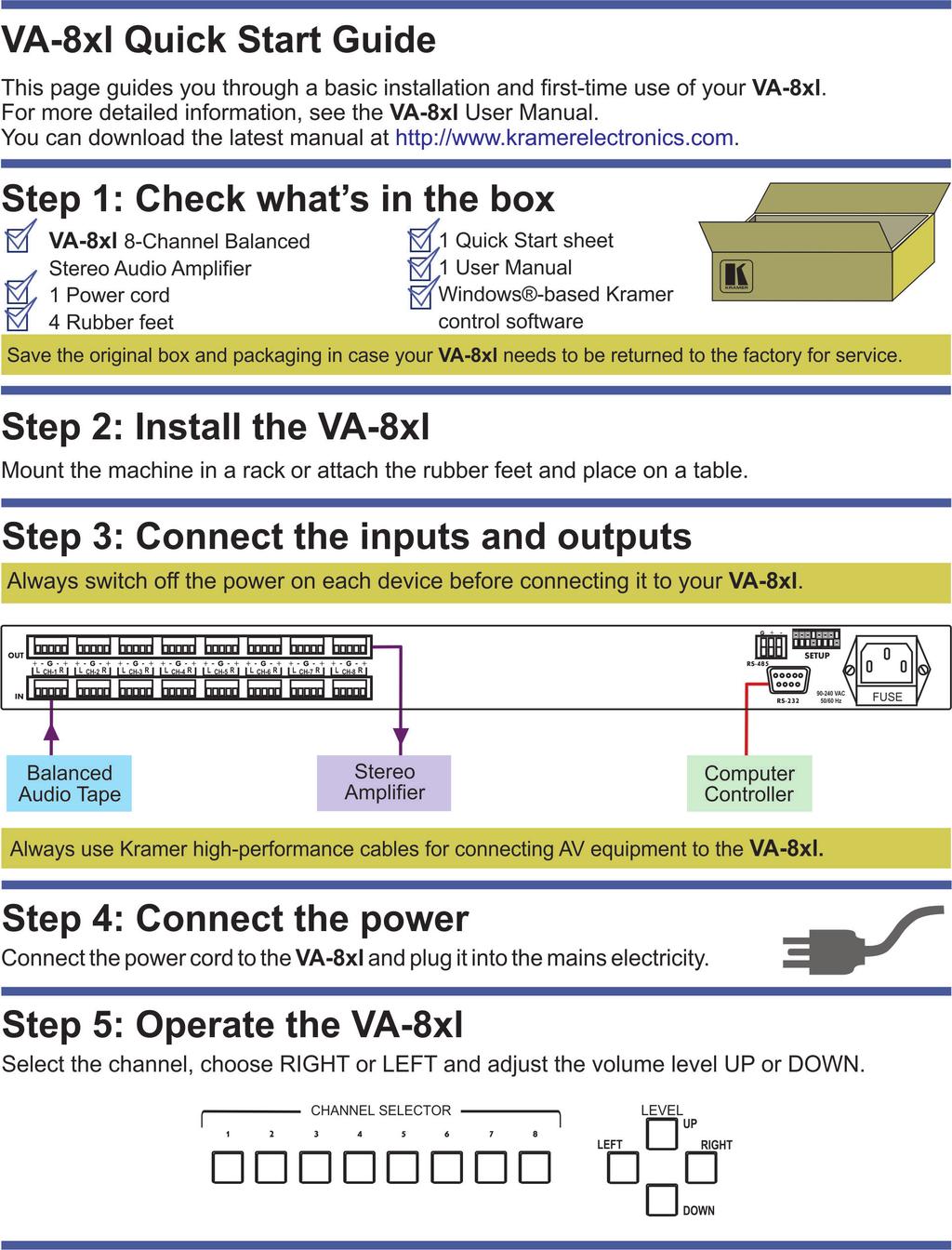
9 4 Connecting the VA-8xl i Always switch off the power to each device before connecting it to your VA-8xl. After connecting your VA-8xl, connect its power and then switch on the power to each device. To connect the VA-8xl as illustrated in the example in Figure 6: 1. Using the appropriate wiring shown in the figures below, connect up to 8 balanced stereo audio sources (for example, a tape deck) to INPUT CHANNEL 1 8 via terminal block connectors: You do not have to connect all channels. 2. Using the appropriate wiring shown in the figures below, connect up to 8 balanced stereo audio acceptors (for example, a stereo amplifier) to OUTPUT CHANNEL 1 8 via terminal block connectors: You do not have to connect all channels. 3. If required, connect a PC via RS-232, (see Page 8). Figure 3: Balanced Stereo Audio Connection Figure 4: Unbalanced Stereo Audio Input Connection Figure 5: Unbalanced Stereo Audio Output Connection 6 VA-8xl - Connecting the VA-8xl

10 Figure 6: Connecting the VA-8xl 8-Channel Balanced Stereo Audio Amplifier VA-8xl - Connecting the VA-8xl 7
11 5 Operating the VA-8xl When switching on the VA-8xl (after a previous session), the VA-8xl briefly scans each channel (stored in the non-volatile memory), showing the settings in the LED displays. After that, the VA-8xl goes to channel 1, and shows its gain/attenuation level in db. During regular work, the VA-8xl shows the status of the last channel you observed and/or changed. To observe the status of a channel: Press a CHANNEL SELECTOR button. That CHANNEL SELECTOR button illuminates for about 20 seconds and the decibel values of the selected channel appear in the dimmed LED displays When the LEDs are dimmed, you cannot change the gain or attenuation - the values are for observation only You can control the amplifier gain of the left and right channels via the front panel buttons, or remotely via RS-232 or RS-485. You can increase or decrease the gain in increments of 0.5dB from -95dB up to +31dB. You can control the amplifier gain of the left and/or right channels separately or together (see Section 5.1). 5.1 Adjusting the Gain/Attenuation of the Channels To adjust the amplifier gain or the attenuation: 1. Press the appropriate CHANNEL SELECTOR button. That CHANNEL SELECTOR button illuminates and the decibel values of the selected channel appear in the dimmed LED displays (stored in the non-volatile memory). (When the LEDs are dimmed, you cannot change the gain or attenuation - the values are for observation only). 2. Press the LEFT LEVEL and/or the RIGHT LEVEL button. The decibel values of the selected channel appear in the bright LEFT and/or RIGHT LED display. 8 VA-8xl - Operating the VA-8xl
12 3. Press the UP or DOWN button once to increase or decrease, as appropriate, in increments of 0.5dB. Press and hold the UP or DOWN button, to increase or decrease the decibel level by a significant amount. 4. Press the LEFT LEVEL or the RIGHT LEVEL button to set the level. The bright LEFT and/or RIGHT LED display becomes dim again, preventing unintentionally altering the settings. 5.2 Storing and Recalling Setups You can store/recall up to 15 settings in the non-volatile memory, via the front panel buttons, or remotely via RS-232 or RS-485. A setting refers to the gain/attenuation level of the selected channel that appears in the dimmed LED displays, and each setting includes all 8 channels. To store a setting, via the front panel buttons: 1. When the LED displays are dimmed, press the DOWN button. The abbreviation StO (store) appears in the LEFT LED display. 2. Choose a setup number (between 1 to 8), by pressing the appropriate CHANNEL SELECTOR button. The abbreviation StO (store) appears in the LEFT LED display and the setup number appears in the RIGHT LED display. 3. Press the same CHANNEL SELECTOR button again. The memory stores the chosen setup number. As confirmation, for a few seconds, YES appears in the LEFT LED display and the setup number appears in the RIGHT LED display. Note: Saving a setup to an previously allocated setup number, overwrites the previous setup To cancel, press the LEFT or RIGHT button VA-8xl - Operating the VA-8xl 9
13 To recall a setting, via the front panel buttons, do the following: 1. When the LED displays are dimmed, press the UP button. The abbreviation rcl (recall) appears in the LEFT LED display. 2. Press the appropriate CHANNEL SELECTOR button. The abbreviation rcl (recall) appears in the LEFT LED display and the number of that CHANNEL SELECTOR button appears in the RIGHT LED display. 3. Press the same CHANNEL SELECTOR button again. The memory recalls the setup. As confirmation, for a few seconds, YES appears in the LEFT LED display and the setup number appears in the RIGHT LED display. If no setting is stored in the non-volatile memory with that setup #, NO appears in the LEFT LED display and the setup number appears in the RIGHT LED display. Note: Recalling a setup implements the amplifier gain or the attenuation immediately 10 VA-8xl - Operating the VA-8xl
14 6 Controlling the VA-8xl You can control a single VA-8xl unit (see Section 6.1) or configure up to a 120 channel balanced stereo audio amplifier, using 15 units via RS-485 or RS-232 (see Section 6.3). 6.1 Controlling a Single VA-8xl Unit To connect and control a single VA-8xl unit, connect the following to the rear panel: PC or other controller, see Section 6.2: Preparing the RS-232 Port on a Single Unit Set the DIP-switches, see Section Power cord 6.2 Preparing the RS-232 Port on a Single Unit You can connect to the unit via a crossed RS-232 connection, using for example, a PC. A crossed cable or null-modem is required as shown in method A and B respectively. If a shielded cable is used, connect the shield to pin 5. Method A (Figure 7) Connect the RS pin D-sub port on the unit via a crossed cable (only pin 2 to pin 3, pin 3 to pin 2, and pin 5 to pin 5 need be connected) to the RS pin D-sub port on the PC. Note: There is no need to connect any other pins PC Figure 7: Crossed Cable RS-232 Connection Hardware flow control is not required for this unit. In the rare case where a controller requires hardware flow control, short pin 1 to 7 and 8, and pin 4 to 6 on the controller side. VA-8xl - Controlling the VA-8xl 11
15 Method B (Figure 8) Connect the RS pin D-sub port on the unit via a straight (flat) cable to the null-modem adapter, and connect the null-modem adapter to the RS pin D-sub port on the PC. The straight cable usually contains all nine wires for a full connection of the D-sub connector. Because the null-modem adapter (which already includes the flow control jumpering described in Method A above) only requires pins 2, 3 and 5 to be connected, you are free to decide whether to connect only these 3 pins or all 9 pins Null-Modem Adapter to PC Figure 8: Straight Cable RS-232 Connection with a Null Modem Adapter DIP-Switch Settings Configure the VA-8xl by setting the DIP-switches as defined in Figure 9: Figure 9: Rear Panel DIP-switches (Factory Default) DIP # Function: 1-4 Set the MACHINE # (see Section 6.2.2) 5 Not used 6 RS-485 termination for first and last machine = ON (RS-485 line terminates with 110Ω); for others = OFF (RS-485 line is open) 7/8 Used for the firmware upgrade procedure (see Section 7) Setting the MACHINE # To control a unit via RS-232 or RS-485, each unit has to be identified via its unique MACHINE #. Set the MACHINE # on a VA-8xl unit according to the following table. A valid MACHINE # is from 1 to VA-8xl - Controlling the VA-8xl
16 For a single, stand alone machine, set as MACHINE # 1. MACHINE # DIP-SWITCH ON OFF OFF OFF 2 OFF ON OFF OFF 3 ON ON OFF OFF 4 OFF OFF ON OFF 5 ON OFF ON OFF 6 OFF ON ON OFF 7 ON ON ON OFF 8 OFF OFF OFF ON 9 ON OFF OFF ON 10 OFF ON OFF ON 11 ON ON OFF ON 12 OFF OFF ON ON 13 ON OFF ON ON 14 OFF ON ON ON 15 ON ON ON ON 6.3 Configuring up to a 120 Channel Balanced Stereo Audio Amplifier To connect up to 15 VA-8xl units, do the following: Connect the balanced/unbalanced audio sources/acceptors to the rear panel on each unit (see Section 4) Connect a PC or other controller (see Section 6.3.1) Set the DIP-switches on each unit (see Section 6.2.1) Connect the power cord on each unit Figure 10 illustrates how to configure up to 15 VA-8xl units. VA-8xl - Controlling the VA-8xl 13
17 Figure 10: Configuring up to 15 VA-8xl Units Connecting a Control Interface on a Set of Units To connect the control interface on a set of units, do one of the following: Connect the RS-232 port on the first VA-8xl unit to a PC or other controller, and then connect the RS-232 port on each of the VA-8xl units, using the specially prepared RS-232 cable (see Section 6.3.2) or Connect a PC or other controller to the RS-232 in 9-pin D-sub (F) port on a Kramer Tools VP-43xl Interface Converter and connect the RS-485 port on the VP-43xl to the RS-485 ports on each of the VA-8xl units (see Section 6.3.3) Preparing the RS-232 Port on a Set of Units To connect a PC to a set of VA-8xl units do the following: 1. Prepare the RS pin D-sub (F) connector (A), by connecting PIN 4 to PIN 6 and connecting PINS 8, 7, and 1 together. 14 VA-8xl - Controlling the VA-8xl
18 2. Attach the RS pin D-sub (F) connector (A) to another RS pin D-sub (M) connector (B) by connecting PIN 5 to PIN 5, PIN 3 to PIN 2, and PIN 2 to PIN Connect the RS pin D-sub (F) connector (A) to your PC s RS pin D-sub (M) port. 4. Attach the RS pin D-sub (M) connector (B) to another RS pin D-sub (M) connector (C), by connecting PIN 5 to PIN 5, PIN 8 to PIN 3, PIN 9 to PIN Connect the RS pin D-sub (M) connector (B) to the RS pin D-sub (F) port on the first VA-8xl unit. 6. Attach the RS pin D-sub (M) connector (C) to another RS pin D-sub (M) connector, if required, by connecting PIN 5 to PIN 5, PIN 8 to PIN 3, PIN 9 to PIN Connect the RS pin D-sub (M) connector (C) to the RS pin D-sub (F) port on the next VA-8xl unit. Figure 11: Preparing the RS-232 Connectors VA-8xl - Controlling the VA-8xl 15
19 6.3.3 Connecting the RS-485 Control Interface To connect an RS-485 connector on one VA-8xl unit to an RS-485 connector on another unit: 1. Connect the + PIN on the first VA-8xl unit to the + PIN on the second VA-8xl unit 2. Connect the - PIN on the first VA-8xl unit to the - PIN on the second VA-8xl unit 3. If shielded cable is used for an RS-485 connection, connect the shield to the Ground PIN. Figure 12 illustrates the RS-485 line that connects: Between each VA-8xl unit To the PC via a Kramer Tools VP-43xl Interface Converter (connect the PC s 9-pin D-sub COM port to the RS-232 in 9-pin D-sub (F) port on the VP-43xl. Next, connect the RS-485 port on the VP-43xl to the RS-485 ports on the VA-8xl units) 16 VA-8xl - Controlling the VA-8xl
20 Figure 12: An RS-485 Control Interface Setup VA-8xl - Controlling the VA-8xl 17
21 7 Upgrading the Flash Memory The VA-8xl firmware is located in FLASH memory, which lets you upgrade to the latest Kramer firmware version in minutes! The process involves: Downloading from the Internet (see Section 7.1) Connecting the PC to the RS-232 port (see Section 7.2) Upgrading Firmware (see Section 7.3) 7.1 Downloading from the Internet You can download the up-to-date file from the Internet. To do so: 1. Go to our Web site at and download the file: FLIP_Va8xl.zip from the Technical Support section. 2. Extract the file: FLIP_Va8xl.zip to a folder (for example, C:\Program Files\Kramer Flash). 7.2 Connecting the PC to the RS-232 Port Before installing the latest Kramer firmware version on a VA-8xl unit, do the following: 1. Connect the RS pin D-sub rear panel port on the VA-8xl unit to the null modem adapter and connect the null modem adapter with a 9-wire flat cable to the RS pin D-sub COM port on your PC (see Section 4). It is recommended that you use COM port 2 (default). However, if your computer has only one COM port, open the file: Va8xl.cfg (located at C:\Program Files\Kramer Flash\Va8xl.cfg) in Notepad, and change set port COM2 to set port COM1. 2. Set the DIP-switches as follows: Set DIP 8 ON Set DIP 7 ON 18 VA-8xl - Upgrading the Flash Memory

22 3. Connect the power cord and turn the POWER switch on the VA-8xl ON. The LED displays may show erratic data, which should be ignored. 7.3 Upgrading Firmware Follow these steps to upgrade the firmware: 1. Double click the desktop icon: Shortcut to FLIP.EXE. The Splash screen appears as follows: Figure 13: Splash Screen 2. After a few seconds, the Splash screen is replaced by the Atmel Flip window: VA-8xl - Upgrading the Flash Memory 19
.")
. If COM 2 was not selected (see Section 7.2), an RS-232 error message appears.")
23 Figure 14: Atmel Flip Window 3. Press the keyboard shortcut key F4 (or select the Read Configuration File command from the File menu, or press the keys: Alt FR). The Open Configuration File window appears: Figure 15: Open Configuration File Select Window 4. Choose the file: Va8xl.cfg (by double-clicking it). If COM 2 was not selected (see Section 7.2), an RS-232 error message appears. In the Atmel Flip window, the Operations Flow column is disabled, and crosses appear in the third column. 20 VA-8xl - Upgrading the Flash Memory


24 Figure 16: Atmel Flip Window (RS-232 Communication) 5. Click OK and press the keyboard shortcut key F3 (or select the Communication / RS232 command from the Settings menu, or press the keys: Alt SCR). The RS232 window appears. Change the COM port: Figure 17: RS-232 Window 6. Click Connect. In the Atmel Flip window, in the Operations Flow column, the Run button is active, and the name of the chip appears as the name of the third column: T89C51RD2. Verify that in the Buffer Information column, the HEX File: Va8xl.hex appears. VA-8xl - Upgrading the Flash Memory 21
.")
25 Figure 18: Atmel Flip Window (Connected) 7. Click Run. After each stage in the operation is completed, the check-box for that stage becomes colored green (see also the blue progress indicator on the status bar). When the operation is completed, all 4 check-boxes will be colored green and the status bar message: Memory Verify Pass appears: If an error message: Not Finished shows, click Run again. 22 VA-8xl - Upgrading the Flash Memory

26 Figure 19: Atmel Flip Window (Operation Completed) 8. Close the Atmel Flip window. 9. Turn the POWER switch on the VA-8xl OFF. 10. Disconnect the RS pin D-sub rear panel port on the VA-8xl unit from the null modem adapter. 11. Set DIP 7 OFF. 12. Set DIP 8 OFF. 13. Turn the POWER switch on the VA-8xl ON. Upon initialization, the new VA-8xl software version shows in the RIGHT LED display. VA-8xl - Upgrading the Flash Memory 23
27 8 Technical Specifications INPUTS: OUTPUTS: GAIN: 8 balanced stereo audio +4dBm / 30kΩ on detachable terminal blocks 8 balanced stereo audio +4dBm / 50Ω on detachable terminal blocks -95dB to +31dB MAX. OUTPUT LEVEL: >20dBu balanced (TND +N <0.01) BANDWIDTH (-0.3dB): NOISE FLOOR: THD + NOISE: CONTROLS: INDICATORS: OPERATING TEMPERATURE: STORAGE TEMPERATURE: HUMIDITY: POWER SOURCE: DIMENSIONS: WEIGHT: ACCESSORIES: 20 Hz to 40 khz <90dB (GAIN 0dB) 0.006%, +4dBu 1kHz Front pushbuttons, RS-232, and RS-485 Gain in db for left and right channels 0 to +55 C (32 to 131 F) -45 to +72 C (-49 to 162 F) 10% to 90%, RHL non-condensing V AC, 13VA 19 x 7 x 1U (W, D, H) rack-mountable 3.5kg (7.8lbs) approx. Power cord, null modem adapter, Windows -based control software Specifications are subject to change without notice at 24 VA-8xl - Technical Specifications
28 9 Default Communication Parameters RS-232 Protocol 2000 Baud Rate: 9600 Data Bits: 8 Stop Bits: 1 Parity: None Command Format: HEX Example (Output 1 to Input 1): 0x01, 0x81, 0x81, 0x81 Ethernet IP Address: TCP Port Number: 5000 Network Mask: Default Gateway: VA-8xl - Default Communication Parameters 25
29 10 Kramer Protocol 2000 The VA-8xl is compatible with Kramer s Protocol 2000 (version 0.50). This RS-232 / RS-485 communication protocol uses four bytes of information as defined below: 1st BYTE: Bit 7 (MSB) Defined as 0. Bit for sending information to the switchers (from the PC) 1 - for sending to the PC (from the switcher). Bits 5 0 INSTRUCTION The function that the switcher is to perform is defined in the INSTRUCTION table below. Similarly, if a function is performed via the machine s front panel, then these bits are set according to the INSTRUCTION NO. that was performed. 2nd BYTE: Bit 7 (MSB) Defined as 1. Bits 4 0 Channel number Bit 5 Left (set to 1 when referring to the left channel) Bit 6 Right (set to 1 when referring to the right channel) Note: To mute with regular attenuation use Bit 5 and 6 = 1 To mute immediately use Bit 5 and 6 = 0, however there may be a pop or click on the output of the muted channel. 3rd BYTE: Bit 7 (MSB) Defined as 1. Bits least significant bits of data 4th BYTE: Bit 7 (MSB) Defined as 1. Bit 5 MSB of data (7 LSBs are in 3rd byte). Bits 4 0 MACHINE NUMBER. For RS-232, a null-modem connection between the machine and controller is used. For both RS-232/RS-485 interfaces the default data rate is 9600 baud, with no parity, 8 data bits and 1 stop bit. All the values in the table are decimal, unless otherwise stated INSTRUCTION # DESCRIPTION 3rd BYTE 22dec SET AUDIO GAIN Set 7 LSBs of gain value (16hex) Gain (db) = 31.5 (0.5x(255-DATA)) 24dec (18hex) 25dec (19hex) EXAMPLES INCREASE / DECREASE AUDIO GAIN REQUEST AUDIO GAIN 0 - increase gain 1 - decrease gain As in Instruction 22dec above. When requesting both channels, the reply is: For equal left and right gain: bits 5 = bit 6 For unequal left and right gain: bits 6 = 0; bit 5 = 1 for reply for left channel In addition to the above, instructions 15, 18, 19, 20, 61, 62 (decimal) of Kramer s Protocol 2000 are also fully implemented in the unit. For instructions 18 and 19, setups 01 to 15 (decimal) are valid. See the following examples: COMMAND EXAMPLES (MACHINE # 1) 16h E7h 90h 81h Set channel 7 both left and right gain -88dB 16h AAh FFh 81h Set channel 10 left gain -32.5dB 16h CAh COh A1h Set channel 10 right gain 0dB 16h FOh DOh A1h Set channel 16 both left and right gain +8dB 18h EFh 80h 81h Increment (increase) gain on 0.5dB on left and right of channel 15 19h CFh 80h 81h Request gain of channel 15 right. If the gain is 0dB for both left and right channels, then the reply would be: 59h EFh COh A1h 19h EEh 80h 81h Request gain of channel 14 both left and right. If the gain is different for the left and right channels, then, for +3dB gain in the left channel the reply would be: 59h AEh C6h A1h 26 VA-8xl - Kramer Protocol 2000
30 The following tables define the VA-8xl hex codes for attenuation gain control, amplification gain control and the channel number codes Hex Codes for Attenuation Gain Control Gain (db) LED Hex Codes Gain (db) LED Hex Codes Gain (db) VA-8xl - Kramer Protocol LED Hex Codes Mute XX XX B XX F XX XX B XX F XX XX BA XX F XX XX BB XX F XX XX BC XX F XX XX BD XX F XX XX BE XX F XX XX BF XX F XX XX C XX F XX XX C XX F XX 8A XX C XX FA XX 8B XX C XX FB XX 8C XX C XX FC XX 8D XX C XX FD XX 8E XX C XX FE XX 8F XX C XX FF XX XX C XX 80 A XX XX C XX 81 A XX XX CA XX 82 A XX XX CB XX 83 A XX XX CC XX 84 A XX XX CD XX 85 A XX XX CE XX 86 A XX XX CF XX 87 A XX XX D XX 88 A XX XX D XX 89 A XX 9A XX D XX 8A A XX 9B XX D XX 8B A XX 9C XX D XX 8C A XX 9D XX D XX 8D A XX 9E XX D XX 8E A XX 9F XX D XX 8F A XX A XX D XX 90 A XX A XX D XX 91 A XX A XX DA XX 92 A XX A XX DB XX 93 A XX A XX DC XX 94 A XX A XX DD XX 95 A XX A XX DE XX 96 A XX A XX DF XX 97 A XX A XX E XX 98 A XX A XX E XX 99 A XX AA XX E XX 9A A XX AB XX E XX 9B A XX AC XX E XX 9C A XX AD XX E XX 9D A XX AE XX E XX 9E A XX AF XX E XX 9F A XX B XX E XX A0 A XX B XX E XX A1 A1
31 Gain LED Hex Codes Gain LED Hex Codes Gain LED Hex Codes (db) (db) (db) XX B XX EA XX A2 A XX B XX EB XX A3 A XX B XX EC XX A4 A XX B XX ED XX A5 A XX B XX EE XX A6 A XX B XX EF XX A7 A XX A8 A XX B0 A XX B8 A XX A9 A XX B1 A XX B9 A XX AA A XX B2 A XX BA A XX AB A XX B3 A XX BB A XX AC A XX B4 A XX BC A XX AD A XX B5 A XX BD A XX AE A XX B6 A XX BE A XX AF A XX B7 A XX BF A BHex Codes for Amplification Gain Control Gain (db) LED Hex Codes Gain (db) LED Hex Codes Gain (db) LED Hex Codes XX C0 A XX D6 A XX EC A XX C1 A XX D7 A XX ED A XX C2 A XX D8 A XX EE A XX C3 A XX D9 A XX EF A XX C4 A XX DA A XX F0 A XX C5 A XX DB A XX F1 A XX C6 A XX DC A XX F2 A XX C7 A XX DD A XX F3 A XX C8 A XX DE A XX F4 A XX C9 A XX DF A XX F5 A XX CA A XX E0 A XX F6 A XX CB A XX E1 A XX F7 A XX CC A XX E2 A XX F8 A XX CD A XX E3 A XX F9 A XX CE A XX E4 A XX FA A XX CF A XX E5 A XX FB A XX D0 A XX E6 A XX FC A XX D1 A XX E7 A XX FD A XX D2 A XX E8 A XX FE A XX D3 A XX E9 A XX FF A XX D4 A XX EA A XX D5 A XX EB A BChannel Number Codes Channel Left Right Both (L & R) Channel Left Right Both (L & R) 1 A1 C1 E1 9 A9 C9 E9 2 A2 C2 E2 10 AA CA EA 3 A3 C3 E3 11 AB CB EB 4 A4 C4 E4 12 AC CC EC 5 A5 C5 E5 13 AD CD ED 6 A6 C6 E6 14 AE CE EE 7 A7 C7 E7 15 AF CF EF 8 A8 C8 E8 16 B0 D0 F0 28 VA-8xl - Kramer Protocol 2000

32 VA-8xl - Kramer Protocol


33 !! " " P/N: Rev: 1
KRAMER ELECTRONICS LTD. USER MANUAL MODEL: VS Port RS-422 Matrix Switcher. P/N: Rev 4
 KRAMER ELECTRONICS LTD. USER MANUAL MODEL: VS-4228 8-Port RS-422 Matrix Switcher P/N: 2900-002033 Rev 4 6 Contents 1 Introduction 1 2 Getting Started 2 2.1 Achieving the Best Performance 2 3 Overview
USER MANUAL. VS Port RS-422 Matrix Switcher MODEL: P/N: Rev 5
 KRAMER ELECTRONICS LTD. USER MANUAL MODEL: VS-4228 8-Port RS-422 Matrix Switcher P/N: 2900-0033 Rev 5 Contents 1 Introduction 1 2 Getting Started 2 2.1 Achieving the Best Performance 2 2.2 Safety Instructions
KRAMER ELECTRONICS LTD. USER MANUAL MODEL: VS-808TP 8x8 Twisted Pair Matrix Switcher. P/N: Rev 1
 KRAMER ELECTRONICS LTD. USER MANUAL MODEL: VS-808TP 8x8 Twisted Pair Matrix Switcher P/N: 2900-300147 Rev 1 Contents 1 Introduction 1 2 Getting Started 2 2.1 Achieving the Best Performance 2 2.2 Using
USER MANUAL. VS-311H Automatic HDMI/Audio Switcher MODEL: P/N: Rev 3
 KRAMER ELECTRONICS LTD. USER MANUAL MODEL: VS-311H Automatic HDMI/Audio Switcher P/N: 2900-000666 Rev 3 Contents 1 Introduction 1 2 Getting Started 2 2.1 Achieving the Best Performance 2 2.2 Safety Instructions
KRAMER ELECTRONICS LTD. USER MANUAL MODEL: VM-24H 2 Input 1:4 HDMI Distributor. P/N: Rev 4
 KRAMER ELECTRONICS LTD. USER MANUAL MODEL: VM-24H 2 Input 1:4 HDMI Distributor P/N: 2900-000664 Rev 4 Contents 1 Introduction 1 2 Getting Started 2 2.1 Achieving the Best Performance 2 2.2 Safety Instructions
Kramer Electronics, Ltd. USER MANUAL. Model: TP Channel UXGA/Audio/RS-232 to CAT 5 Transmitter
 Kramer Electronics, Ltd. USER MANUAL Model: TP-185 8 Channel UXGA/Audio/RS-232 to CAT 5 Transmitter Contents Contents 1 Introduction 1 2 Getting Started 1 2.1 Quick Start 2 3 Overview 3 3.1 Shielded Twisted
KRAMER ELECTRONICS LTD. USER MANUAL MODEL: VS-41H 4x1 HDMI Switcher. P/N: Rev 7
 KRAMER ELECTRONICS LTD. USER MANUAL MODEL: VS-41H 4x1 HDMI Switcher P/N: 2900-000667 Rev 7 Contents 1 Introduction 1 2 Getting Started 2 2.1 Achieving the Best Performance 2 2.2 Safety Instructions 3
KRAMER ELECTRONICS LTD. USER MANUAL MODEL: 905xl Power Amplifier. P/N: Rev 3
 KRAMER ELECTRONICS LTD. USER MANUAL MODEL: 905xl Power Amplifier P/N: 2900-300196 Rev 3 Contents 1 Introduction 1 2 Getting Started 2 2.1 Achieving the Best Performance 2 2.2 Safety Instructions 2 2.3
Kramer Electronics, Ltd. USER MANUAL. Model: VS-3232A. 32x32 Audio Matrix Switcher
 Kramer Electronics, Ltd. USER MANUAL Model: VS-3232A 32x32 Audio Matrix Switcher Contents Contents 1 Introduction 1 2 Getting Started 1 2.1 Quick Start 1 3 Overview 3 4 Your Balanced Stereo Audio Matrix
USER MANUAL. VM-28H 2 Input 1:8 HDMI Distributor. VM-216H 2 Input 1:16 HDMI Distributor MODEL: P/N: Rev 5
 KRAMER ELECTRONICS LTD. USER MANUAL MODEL: VM-28H 2 Input 1:8 HDMI Distributor VM-216H 2 Input 1:16 HDMI Distributor P/N: 2900-000662 Rev 5 Contents 1 Introduction 1 2 Getting Started 2 2.1 Achieving
Kramer Electronics, Ltd. USER MANUAL. Model: VS-1616A. 16x16 Balanced Stereo Audio Matrix Switcher
 Kramer Electronics, Ltd. USER MANUAL Model: VS-1616A 16x16 Balanced Stereo Audio Matrix Switcher Contents Contents 1 Introduction 1 2 Getting Started 1 3 Overview 2 4 Your Balanced Stereo Audio Matrix
USER MANUAL. VS-88H 8x8 HDMI Matrix Switcher MODEL: P/N: Rev 5
 KRAMER ELECTRONICS LTD. USER MANUAL MODEL: VS-88H 8x8 HDMI Matrix Switcher P/N: 2900-000654 Rev 5 Contents 1 Introduction 1 2 Getting Started 2 2.1 Achieving the Best Performance 2 2.2 Safety Instructions
USER MANUAL V/100V Power Amplifier MODEL: P/N: Rev 4
 KRAMER ELECTRONICS LTD. USER MANUAL MODEL: 920 70V/100V Power Amplifier P/N: 2900-300308 Rev 4 Contents 1 Introduction 1 2 Getting Started 2 2.1 Achieving the Best Performance 2 2.2 Safety Instructions
USER MANUAL. VP-311DVI Automatic DVI/Audio Switcher MODEL: P/N: Rev 3
 KRAMER ELECTRONICS LTD. USER MANUAL MODEL: VP-311DVI Automatic DVI/Audio Switcher P/N: 2900-000120 Rev 3 Contents 1 Introduction 1 2 Getting Started 2 2.1 Achieving the Best Performance 2 2.2 Safety Instructions
KRAMER ELECTRONICS LTD. USER MANUAL MODEL: VP-4x8 4x8 VGA/UXGA Matrix Switcher. P/N: Rev 3
 KRAMER ELECTRONICS LTD. USER MANUAL MODEL: VP-4x8 4x8 VGA/UXGA Matrix Switcher P/N: 2900-000372 Rev 3 Contents 1 Introduction 1 2 Getting Started 2 2.1 Achieving the Best Performance 2 2.2 Recycling Kramer
Kramer Electronics, Ltd. USER MANUAL. Model: VS-162V. 16x16 Video Matrix Switcher
 Kramer Electronics, Ltd. USER MANUAL Model: VS-162V 16x16 Video Matrix Switcher Contents Contents 1 Introduction 1 2 Getting Started 1 2.1 Quick Start 1 3 Overview 3 4 Your Video Matrix Switcher 4 4.1
KRAMER ELECTRONICS LTD. USER MANUAL MODEL: VS-161H 16x1 HDMI Switcher. P/N: Rev 6
 KRAMER ELECTRONICS LTD. USER MANUAL MODEL: VS-161H 16x1 HDMI Switcher P/N: 2900-000665 Rev 6 Contents 1 Introduction 1 2 Getting Started 2 2.1 Achieving the Best Performance 2 3 Overview 3 3.1 About HDMI
Kramer Electronics, Ltd. USER MANUAL. Model: PL-8. Low Voltage Relay Controller
 Kramer Electronics, Ltd. USER MANUAL Model: PL-8 Low Voltage Relay Controller Contents Contents 1 Introduction 1 2 Getting Started 1 2.1 Quick Start 2 3 Overview 2 4 Your PL-8 Low Voltage Relay Controller
USER MANUAL. VP-211K Automatic UXGA / Audio Switcher MODEL: P/N: Rev 3
 KRAMER ELECTRONICS LTD. USER MANUAL MODEL: VP-211K Automatic UXGA / Audio Switcher P/N: 2900-000414 Rev 3 Contents 1 Introduction 1 2 Getting Started 2 2.1 Achieving the Best Performance 2 2.2 Safety
Kramer Electronics, Ltd.
 Kramer Electronics, Ltd. Preliminary USER MANUAL Model: VA-1VGAN EDID Capture Introduction Contents 1 Introduction 1 2 Getting Started 1 2.1 Quick Start 2 3 Overview 3 3.1 Defining EDID 4 4 Your VA-1VGAN
KRAMER ELECTRONICS LTD. USER MANUAL MODEL: VA-1VGAN EDID Capture. P/N: Rev 2
 KRAMER ELECTRONICS LTD. USER MANUAL MODEL: VA-1VGAN EDID Capture P/N: 2900-000513 Rev 2 Contents 1 Introduction 1 2 Getting Started 2 2.1 Achieving the Best Performance 2 2.2 Recycling Kramer Products
Kramer Electronics, Ltd.
 Kramer Electronics, Ltd. Preliminary USER MANUAL Model: FC-50 RS-232 Range Extender Contents Contents 1 Introduction 1 2 Getting Started 1 2.1 Quick Start 2 3 Overview 3 3.1 About the Power Connect Feature
USER MANUAL. VS-21HDCP-IR 2x1 DVI Switcher MODEL: P/N: Rev 5
 KRAMER ELECTRONICS LTD. USER MANUAL MODEL: VS-21HDCP-IR 2x1 DVI Switcher P/N: 2900-000556 Rev 5 Contents 1 Introduction 1 2 Getting Started 2 2.1 Achieving the Best Performance 2 2.2 Safety Instructions
USER MANUAL. VS-808TP 8x8 Twisted Pair Matrix Switcher MODEL: P/N: Rev 2
 KRAMER ELECTRONICS LTD. USER MANUAL MODEL: VS-808TP 8x8 Twisted Pair Matrix Switcher P/N: 2900-300147 Rev 2 Contents 1 Introduction 1 2 Getting Started 2 2.1 Achieving the Best Performance 2 2.2 Safety
USER MANUAL. VA-1USB-T USB Transmitter. VA-1USB-R USB Receiver MODELS: P/N: Rev 3
 KRAMER ELECTRONICS LTD. USER MANUAL MODELS: VA-1USB-T USB Transmitter VA-1USB-R USB Receiver P/N: 2900-300209 Rev 3 Contents 1 Introduction 1 2 Getting Started 2 2.1 Achieving the Best Performance 2 2.2
USER MANUAL. PT-1C EDID Processor MODEL: P/N: Rev 3
 KRAMER ELECTRONICS LTD. USER MANUAL MODEL: PT-1C EDID Processor P/N: 2900-300276 Rev 3 Contents 1 Introduction 1 2 Getting Started 2 2.1 Achieving the Best Performance 2 2.2 Recycling Kramer Products
USER MANUAL. SL-1N Master Room Controller MODEL: P/N: Rev 1
 KRAMER ELECTRONICS LTD. USER MANUAL MODEL: SL-1N Master Room Controller P/N: 2900-300399 Rev 1 Contents 1 Introduction 1 2 Getting Started 2 2.1 Achieving the Best Performance 2 2.2 Safety Instructions
WAV-5 WAV-5C WAV-3 WA-1H WAV-1R WAV-1RP
 KRAMER ELECTRONICS LTD. USER MANUAL MODELS: WAV-5 WAV-5C WAV-3 WA-1H WAV-1R WAV-1RP Wall Plate Series P/N: 2900-300124 Rev 2 Contents 1 Introduction 1 2 Getting Started 2 2.1 Achieving the Best Performance
USER MANUAL. VM-2HDCPxl 1:2 DVI Distributor MODEL: P/N: Rev 3
 KRAMER ELECTRONICS LTD. USER MANUAL MODEL: VM-2HDCPxl 1:2 DVI Distributor P/N: 2900-000510 Rev 3 Contents 1 Introduction 1 2 Getting Started 2 2.1 Achieving the Best Performance 2 2.2 Safety Instructions
USER MANUAL. VM-2Hxl 1:2 HDMI Distributor MODEL: P/N: Rev 3
 KRAMER ELECTRONICS LTD. USER MANUAL MODEL: VM-2Hxl 1:2 HDMI Distributor P/N: 2900-000672 Rev 3 Contents 1 Introduction 1 2 Getting Started 2 2.1 Achieving the Best Performance 2 2.2 Safety Instructions
USER MANUAL. PT-101UHD HDMI Repeater MODEL: P/N: Rev 3.
 USER MANUAL MODEL: PT-101UHD HDMI Repeater P/N: 2900-300492 Rev 3 www.kramerav.com Contents 1 Introduction 1 2 Getting Started 2 2.1 Achieving the Best Performance 2 2.2 Safety Instructions 2 2.3 Recycling
Kramer Electronics, Ltd. USER MANUAL. Model: VA-1VGA. EDID Capture
 Kramer Electronics, Ltd. USER MANUAL Model: VA-1VGA EDID Capture Contents Contents 1 Introduction 1 2 Getting Started 1 2.1 Quick Start 2 3 Overview 3 3.1 Defining EDID 3 4 Your VA-1VGA EDID Capture 4
KRAMER ELECTRONICS LTD. USER MANUAL MODEL: VS-401USB 4x1 USB Switcher. P/N: Rev 1
 KRAMER ELECTRONICS LTD. USER MANUAL MODEL: VS-401USB 4x1 USB Switcher P/N: 2900-300029 Rev 1 Contents 1 Introduction 1 2 Getting Started 2 2.1 Achieving the Best Performance 2 2.2 Recycling Kramer Products
Kramer Electronics, Ltd. USER MANUAL. Models: VM-8H, 1:8 HDMI Distributor VM-16H, 1:16 HDMI Distributor
 Kramer Electronics, Ltd. USER MANUAL Models: VM-8H, 1:8 HDMI Distributor VM-16H, 1:16 HDMI Distributor Contents Contents 1 Introduction 1 2 Getting Started 1 2.1 Quick Start 2 3 Overview 3 3.1 Recommendations
KRAMER ELECTRONICS LTD. USER MANUAL MODELS: TP-125xl UXGA/Audio/Data Line Transmitter. TP-126xl UXGA/Audio/Data Line Receiver. P/N: Rev 4
 KRAMER ELECTRONICS LTD. USER MANUAL MODELS: TP-125xl UXGA/Audio/Data Line Transmitter TP-126xl UXGA/Audio/Data Line Receiver P/N: 2900-300206 Rev 4 Contents 1 Introduction 1 2 Getting Started 2 2.1 Achieving
USER MANUAL. RC-43SL 6-Button Room Controller MODEL: P/N: Rev 3.
 USER MANUAL MODEL: RC-43SL 6-Button Room Controller P/N: 2900-300450 Rev 3 www.kramerav.com Contents 1 Introduction 1 2 Getting Started 2 2.1 Achieving the Best Performance 2 2.2 Safety Instructions
KRAMER ELECTRONICS LTD. USER MANUAL MODEL: VS-41HC 4x1 HDMI Switcher. P/N: Rev 4
 KRAMER ELECTRONICS LTD. USER MANUAL MODEL: VS-41HC 4x1 HDMI Switcher P/N: 2900-000423 Rev 4 Contents 1 Introduction 1 2 Getting Started 2 2.1 Achieving the Best Performance 2 2.2 Safety Instructions 3
Kramer Electronics, Ltd. USER MANUAL. Models: TP-125, UXGA / Audio / Data Line Transmitter TP-126, UXGA / Audio / Data Line Receiver
 Kramer Electronics, Ltd. USER MANUAL Models: TP-125, UXGA / Audio / Data Line Transmitter TP-126, UXGA / Audio / Data Line Receiver Contents Contents 1 Introduction 1 2 Getting Started 1 2.1 Quick Start
USER MANUAL. VS-88HDCPxl 8x8 DVI Matrix Switcher MODEL: P/N: Rev 9
 KRAMER ELECTRONICS LTD. USER MANUAL MODEL: VS-88HDCPxl 8x8 DVI Matrix Switcher P/N: 2900-300016 Rev 9 Contents 1 Introduction 1 2 Getting Started 2 2.1 Achieving the Best Performance 2 2.2 Safety Instructions
KRAMER ELECTRONICS LTD. USER MANUAL MODEL: VM-73 Multiformat 1:3 Distribution Amplifier. P/N: Rev 3
 KRAMER ELECTRONICS LTD. USER MANUAL MODEL: VM-73 Multiformat 1:3 Distribution Amplifier P/N: 2900-000544 Rev 3 Contents 1 Introduction 1 2 Getting Started 2 2.1 Achieving the Best Performance 2 2.2 Recycling
Kramer Electronics, Ltd. USER MANUAL. Model: VP-727A-BA. Balanced Audio Switcher
 Kramer Electronics, Ltd. USER MANUAL Model: VP-727A-BA Balanced Audio Switcher Contents Contents 1 Introduction 1 2 Getting Started 1 2.1 Quick Start 1 3 Overview 3 4 Your VP-727A-BA Balanced Audio Switcher
USER MANUAL. RC-43SL 6-Button Room Controller MODEL: P/N: Rev 1.
 USER MANUAL MODEL: RC-43SL 6-Button Room Controller P/N: 2900-300450 Rev 1 www.kramerav.com Contents 1 Introduction 1 2 Getting Started 2 2.1 Achieving the Best Performance 2 2.2 Safety Instructions
USER MANUAL. SL-10 Master Room Controller MODEL: P/N: Rev 4
 KRAMER ELECTRONICS LTD. USER MANUAL MODEL: SL-10 Master Room Controller P/N: 2900-000581 Rev 4 Contents 1 Introduction 1 2 Getting Started 2 2.1 Achieving the Best Performance 2 2.2 Safety Instructions
USER MANUAL. RS-232 Extender MODEL: P/N: Rev 1
 USER MANUAL MODEL: RS-232 Extender P/N: 2900-300284 Rev 1 Contents 1 Introduction 1 2 Getting Started 2 2.1 Achieving the Best Performance 2 2.2 Safety Instructions 3 2.3 Recycling Kramer Products 3 3
Kramer Electronics, Ltd. USER MANUAL. Model: VM-50AN. 1:5 Audio Distributor
 Kramer Electronics, Ltd. USER MANUAL Model: VM-50AN 1:5 Audio Distributor Contents Contents 1 Introduction 1 2 Getting Started 1 2.1 Quick Start 1 3 Overview 3 4 Your Audio VM-50AN 1:5 Distributor 4 5
Kramer Electronics, Ltd. USER MANUAL. Model: VP-8x8. 8x8 VGA / UXGA Matrix Switcher
 Kramer Electronics, Ltd. USER MANUAL Model: VP-8x8 8x8 VGA / UXGA Matrix Switcher Contents Contents 1 Introduction 1 2 Getting Started 1 3 Overview 2 4 Your VP-8x8 8x8 VGA / UXGA Matrix Switcher 2 5 Connecting
Kramer Electronics, Ltd. USER MANUAL. Model: VP :8 XGA / Balanced Stereo Audio DA
 Kramer Electronics, Ltd. USER MANUAL Model: VP-18 1:8 XGA / Balanced Stereo Audio DA Contents Contents 1 Introduction 1 Getting Started 1.1 Quick Start 1 3 Overview 3 4 Your VP-18 1:8 XGA / Balanced Stereo
KRAMER ELECTRONICS LTD. USER MANUAL MODEL: VA-1VGAxl EDID Capture/Emulator. P/N: Rev 2
 KRAMER ELECTRONICS LTD. USER MANUAL MODEL: VA-1VGAxl EDID Capture/Emulator P/N: 2900-300011 Rev 2 Contents 1 Introduction 1 2 Getting Started 2 2.1 Achieving the Best Performance 2 3 Overview 3 3.1 Defining
USER MANUAL. PT-5T/R IR Extender/Repeater MODEL: P/N: Rev 3
 KRAMER ELECTRONICS LTD. USER MANUAL MODEL: PT-5T/R IR Extender/Repeater P/N: 2900-300010 Rev 3 Contents 1 Introduction 1 2 Getting Started 2 2.1 Achieving the Best Performance 2 2.2 Safety Instructions
SES-SBA-150W USER MANUAL
 SES-SBA-150W USER MANUAL www.sescom.com Contents Contents 1 Introduction 1 2 Getting Started 1 3 Overview 1 4 Your SES-SBA-150W 2 5 Connecting the SES-SBA-150W 3 5.1 Connecting the Stereo Audio Input 3
USER MANUAL RC-76M/RC-712M MODEL: P/N: Rev 3
 KRAMER ELECTRONICS LTD. USER MANUAL MODEL: RC-76M/RC-712M P/N: 2900-300329 Rev 3 Contents 1 Introduction 1 2 Getting Started 2 2.1 Achieving the Best Performance 2 2.2 Safety Instructions 3 2.3 Recycling
USER MANUAL. TP-145 XGA/Audio/Data Line Transmitter. TP-146 UXGA/Audio/Data Line Receiver MODELS: P/N: Rev 3
 KRAMER ELECTRONICS LTD. USER MANUAL MODELS: TP-145 XGA/Audio/Data Line Transmitter TP-146 UXGA/Audio/Data Line Receiver P/N: 2900-000607 Rev 3 Contents 1 Introduction 1 2 Getting Started 2 2.1 Achieving
USER MANUAL. 671T DVI Optical Transmitter. 671R DVI Optical Receiver MODEL: P/N: Rev 4
 KRAMER ELECTRONICS LTD. USER MANUAL MODEL: 671T DVI Optical Transmitter 671R DVI Optical Receiver P/N: 2900-000484 Rev 4 Contents 1 Introduction 1 2 Getting Started 2 2.1 Achieving the Best Performance
KRAMER ELECTRONICS LTD. USER MANUAL MODEL: VS-801USB 8x1 USB Switcher. P/N: Rev 3
 KRAMER ELECTRONICS LTD. USER MANUAL MODEL: VS-801USB 8x1 USB Switcher P/N: 2900-300030 Rev 3 Contents 1 Introduction 1 2 Getting Started 2 2.1 Achieving the Best Performance 2 3 Overview 3 3.1 Defining
USER MANUAL. PT-580T HDMI Line Transmitter. TP-580T HDMI Line Transmitter. TP-580R HDMI Line Receiver MODELS: P/N: Rev 3
 KRAMER ELECTRONICS LTD. USER MANUAL MODELS: PT-580T HDMI Line Transmitter TP-580T HDMI Line Transmitter TP-580R HDMI Line Receiver P/N: 2900-300340 Rev 3 Contents 1 Introduction 1 2 Getting Started 2
USER MANUAL. RC-76R/RC-78R Room Controllers MODEL: P/N: Rev 2
 KRAMER ELECTRONICS LTD. USER MANUAL MODEL: RC-76R/RC-78R Room Controllers P/N: 2900-300253 Rev 2 Contents 1 Introduction 1 2 Getting Started 2 2.1 Achieving the Best Performance 2 2.2 Safety Instructions
USER MANUAL. RC-54DL KNET Auxiliary Control Panel MODEL: P/N: Rev 2
 KRAMER ELECTRONICS LTD. USER MANUAL MODEL: RC-54DL KNET Auxiliary Control Panel P/N: 2900-300130 Rev 2 Contents 1 Introduction 1 2 Getting Started 2 2.1 Achieving the Best Performance 2 3 Overview 3 3.1
Kramer Electronics, Ltd. USER MANUAL. Model: WP-101. XGA/Stereo Audio Line Driver
 Kramer Electronics, Ltd. USER MANUAL Model: WP-101 XGA/Stereo Audio Line Driver Contents Contents 1 Introduction 1 2 Getting Started 1 3 Overview 1 3.1 Defining the EDID 2 3.2 Recommendations for Achieving
KRAMER ELECTRONICS LTD. USER MANUAL MODEL: VS-211HA Automatic HDMI Standby Switcher. P/N: Rev 3
 KRAMER ELECTRONICS LTD. USER MANUAL MODEL: VS-211HA Automatic HDMI Standby Switcher P/N: 2900-300378 Rev 3 Contents 1 Introduction 1 2 Getting Started 2 2.1 Achieving the Best Performance 2 2.2 Safety
Kramer Electronics, Ltd. USER MANUAL. Model: VM-80HP. 1:8 Stereo Headphone Distributor
 Kramer Electronics, Ltd. USER MANUAL Model: VM-80HP 1:8 Stereo Headphone Distributor Contents Contents 1 Introduction 1 2 Getting Started 1 3 Overview 2 4 Your VM-80HP 1:8 Stereo Headphone Distributor
USER MANUAL. RC-43T Remote Controller MODEL: P/N: Rev 3
 KRAMER ELECTRONICS LTD. USER MANUAL MODEL: RC-43T Remote Controller P/N: 2900-300301 Rev 3 Contents 1 Introduction 1 2 Getting Started 2 2.1 Achieving the Best Performance 2 2.2 Safety Instructions 3
Kramer Electronics, Ltd. USER MANUAL VM-24HD. 2 x 1:4 HD/SD SDI DA
 Kramer Electronics, Ltd. USER MANUAL VM-24HD 2 x 1:4 HD/SD SDI DA Contents Contents 1 Introduction 1 2 Getting Started 1 2.1 Quick Start 2 3 Overview 3 4 Your VM-24HD 2 x 1:4 HD/SD SDI DA 4 5 Connecting
KRAMER ELECTRONICS LTD. USER MANUAL MODEL: RC-76R/RC-78R Room Controllers. P/N: Rev 5
 KRAMER ELECTRONICS LTD. USER MANUAL MODEL: RC-76R/RC-78R Room Controllers P/N: 2900-300253 Rev 5 Contents 1 Introduction 1 2 Getting Started 2 2.1 Achieving the Best Performance 2 2.2 Safety Instructions
KRAMER ELECTRONICS LTD. USER MANUAL MODELS: TP-580T HDMI Line Transmitter. TP-580R HDMI Line Receiver. P/N: Rev 2
 KRAMER ELECTRONICS LTD. USER MANUAL MODELS: TP-580T HDMI Line Transmitter TP-580R HDMI Line Receiver P/N: 2900-300034 Rev 2 Contents 1 Introduction 1 2 Getting Started 2 2.1 Achieving the Best Performance
Kramer Electronics, Ltd.
 Kramer Electronics, Ltd. Preliminary USER MANUAL Model: 903 Personal Stereo Amplifier Contents Contents 1 Introduction 1 2 Getting Started 1 2.1 Quick Start 2 3 Overview 3 4 Your 903 Personal Stereo Amplifier
USER MANUAL. TP-580Txr HDMI Line Transmitter. TP-580Rxr HDMI Line Receiver MODELS: P/N: Rev 5
 KRAMER ELECTRONICS LTD. USER MANUAL MODELS: TP-580Txr HDMI Line Transmitter TP-580Rxr HDMI Line Receiver P/N: 2900-300088 Rev 5 Contents 1 Introduction 1 2 Getting Started 2 2.1 Achieving the Best Performance
Kramer Electronics, Ltd. USER MANUAL. Model: Cobra MX x16 Matrix Switcher / DA
 Kramer Electronics, Ltd. USER MANUAL Model: Cobra MX-1616 16x16 Matrix Switcher / DA Contents Contents 1 Introduction 1 2 Getting Started 1 3 Overview 1 4 Cobra MX-1616 16x16 Matrix Switcher / DA Operation
Kramer Electronics, Ltd.
 Kramer Electronics, Ltd. Preliminary USER MANUAL Model: VM-1120 1:10 Balanced Stereo Audio Distributor Contents Contents 1 Introduction 1 2 Getting Started 1 2.1 Quick Start 2 3 Overview 3 4 Your Balanced
KRAMER ELECTRONICS LTD. USER MANUAL MODELS: WP-110, XGA Line Transmitter. PT-120, XGA Line Receiver. TP-120, XGA Line Receiver. P/N: Rev 1
 KRAMER ELECTRONICS LTD. USER MANUAL MODELS: WP-110, XGA Line Transmitter PT-120, XGA Line Receiver TP-120, XGA Line Receiver P/N: 2900-300180 Rev 1 Contents 1 Introduction 1 2 Getting Started 2 2.1 Achieving
KRAMER ELECTRONICS LTD. USER MANUAL MODEL: VA-2H EDID Reader-Emulator. P/N: Rev 3
 KRAMER ELECTRONICS LTD. USER MANUAL MODEL: VA-2H EDID Reader-Emulator P/N: 2900-000677 Rev 3 Contents 1 Introduction 1 2 Getting Started 2 2.1 Achieving the Best Performance 2 3 Overview 3 3.1 Defining
USER MANUAL. RC-74DL Master Room Controller MODEL: P/N: Rev 4
 KRAMER ELECTRONICS LTD. USER MANUAL MODEL: RC-74DL Master Room Controller P/N: 2900-000691 Rev 4 Contents 1 Introduction 1 2 Getting Started 2 2.1 Achieving the Best Performance 2 2.2 Safety Instructions
Kramer Electronics, Ltd. USER MANUAL. Model: VS-121HCA. 12 x 1 Stereo Audio - S/PDIF Switcher
 Kramer Electronics, Ltd. USER MANUAL Model: VS-121HCA 12 x 1 Stereo Audio - S/PDIF Switcher Contents Contents 1 Introduction 1 2 Getting Started 1 2.1 Quick Start 2 3 Overview 3 4 Your VS-121HCA Stereo
KRAMER ELECTRONICS LTD. USER MANUAL MODEL: RC-74DL Master Room Controller. P/N: Rev 5
 KRAMER ELECTRONICS LTD. USER MANUAL MODEL: RC-74DL Master Room Controller P/N: 2900-000691 Rev 5 Contents 1 Introduction 1 2 Getting Started 2 2.1 Achieving the Best Performance 2 2.2 Safety Instructions
Kramer Electronics, Ltd. USER MANUAL. Model: WP-209. Wall Plate
 Kramer Electronics, Ltd. USER MANUAL Model: WP-209 Wall Plate Contents Contents 1 Introduction 1 2 Getting Started 1 2.1 Quick Start 1 3 Overview 3 4 Your WP-209 4.1 Your WP-209 Front Panel 4 4 4.2 Your
USER MANUAL. 614T One-Fiber Detachable Optical DVI Transmitter. 614R One-Fiber Detachable Optical DVI Receiver MODELS: P/N: Rev 5
 KRAMER ELECTRONICS LTD. USER MANUAL MODELS: 614T One-Fiber Detachable Optical DVI Transmitter 614R One-Fiber Detachable Optical DVI Receiver P/N: 2900-300249 Rev 5 Contents 1 Introduction 1 2 Getting
KRAMER ELECTRONICS LTD. USER MANUAL MODEL: 622T Dual Link DVI Optical Transmitter. 622R Dual Link DVI Optical Receiver. P/N: Rev 4
 KRAMER ELECTRONICS LTD. USER MANUAL MODEL: 622T Dual Link DVI Optical Transmitter 622R Dual Link DVI Optical Receiver P/N: 2900-000104 Rev 4 Contents 1 Introduction 1 2 Getting Started 2 2.1 Achieving
Kramer Electronics, Ltd. USER MANUAL. Model: TBUS-9. Table Connection Bus
 Kramer Electronics, Ltd. USER MANUAL Model: TBUS-9 Table Connection Bus Contents Contents 1 Introduction 1 2 Getting Started 1 2.1 Quick Start 2 3 Overview 3 4 Your TBUS-9 4 5 Installing the TBUS-9 Table
USER MANUAL. 602T Two-fiber Detachable Optical DVI Transmitter 602R. DVI Receiver MODELS: P/N: Rev 3
 KRAMER ELECTRONICS LTD. USER MANUAL MODELS: 602T Two-fiber Detachable Optical DVI Transmitter 602R Two-fiber Detachable Optical DVI Receiver P/N: 2900-000646 Rev 3 Contents 1 Introduction 1 2 Getting
Kramer Electronics, Ltd.
 Kramer Electronics, Ltd. Preliminary USER MANUAL Model: VM-12HDCP 1:12 DVI Distributor Contents Contents 1 Introduction 1 2 Getting Started 1 2.1 Quick Start 2 3 Overview 3 3.1 About HDCP 4 3.2 Defining
USER MANUAL. 621T DVI Optical Transmitter. 621R DVI Optical Receiver MODEL: P/N: Rev 8
 KRAMER ELECTRONICS LTD. USER MANUAL MODEL: 621T DVI Optical Transmitter 621R DVI Optical Receiver P/N: 2900-000103 Rev 8 Contents 1 Introduction 1 2 Getting Started 2 2.1 Achieving the Best Performance
USER MANUAL. TP-780T HDMI Line Transmitter + POE TP-780R HDMI Line Receiver + POE MODELS: P/N: Rev 2.
 USER MANUAL MODELS: TP-780T HDMI Line Transmitter + POE TP-780R HDMI Line Receiver + POE P/N: 2900-300575 Rev 2 www.kramerav.com Contents 1 Introduction 1 2 Getting Started 2 2.1 Achieving the Best Performance
USER MANUAL. KDS-EN3 HD Video Encoder/Streamer. KDS-DEC3 HD Video Decoder MODELS: P/N: Rev 3
 KRAMER ELECTRONICS LTD. USER MANUAL MODELS: KDS-EN3 HD Video Encoder/Streamer KDS-DEC3 HD Video Decoder P/N: 2900-300375 Rev 3 Contents 1 Introduction 1 2 Getting Started 2 2.1 Achieving the Best Performance
Kramer Electronics, Ltd. USER MANUAL. Model: VM-4HDCPxl. 1:4 DVI Distributor
 Kramer Electronics, Ltd. USER MANUAL Model: VM-4HDCPxl 1:4 DVI Distributor Contents Contents 1 Introduction 1 2 Getting Started 1 2.1 Quick Start 2 3 Overview 3 3.1 About HDCP 3 3.2 Defining EDID 3 3.3
KRAMER ELECTRONICS LTD. USER MANUAL MODELS: TP-121EDID, XGA /Audio Line Transmitter TP-125EDID, XGA. PT-110EDID, XGA Line Transmitter
 KRAMER ELECTRONICS LTD. USER MANUAL MODELS: TP-121EDID, XGA /Audio Line Transmitter TP-123EDID, XGA /Audio/Data Line Transmitter TP-125EDID, XGA /Audio/Data Line Transmitter PT-110EDID, XGA Line Transmitter
4. Specifications and Additional Information
 4. Specifications and Additional Information AGX52004-1.0 8B/10B Code This section provides information about the data and control codes for Arria GX devices. Code Notation The 8B/10B data and control
RC Configuration and Installation Guide
 Kramer Electronics, Ltd. RC Configuration and Installation Guide Revision 8 Intended for Kramer Technical Personnel or external System Integrators. To check that you have the latest version, go to the
Kramer Electronics, Ltd. USER MANUAL. Model: VP-2x2. 2x2 XGA/Audio Matrix Switcher
 Kramer Electronics, Ltd. USER MANUAL Model: VP-2x2 2x2 XGA/Audio Matrix Switcher Contents Contents 1 Introduction 1 2 Getting Started 1 3 Overview 1 4 Your XGA/Audio Matrix Switcher 2 4.1 Connecting the
Gateway Ascii Command Protocol
 Gateway Ascii Command Protocol Table Of Contents Introduction....2 Ascii Commands.....3 Messages Received From The Gateway....3 Button Down Message.....3 Button Up Message....3 Button Maintain Message....4
CIS-331 Exam 2 Fall 2015 Total of 105 Points Version 1
 Version 1 1. (20 Points) Given the class A network address 117.0.0.0 will be divided into multiple subnets. a. (5 Points) How many bits will be necessary to address 4,000 subnets? b. (5 Points) What is
USER MANUAL. Kramer Electronics, Ltd. Models:
 Kramer Electronics, Ltd. USER MANUAL Models: VM-10FW, 1:10 FireWire Distributor/Hub VM-15FW, 1:15 FireWire Distributor/Hub VM-20FW, 1:20 FireWire Distributor/Hub Contents Contents 1 Introduction 1 2 Getting
USER MANUAL. VM-2DP 1:2 DisplayPort Distributor MODEL: P/N: Rev 2
 KRAMER ELECTRONICS LTD. USER MANUAL MODEL: VM-2DP 1:2 DisplayPort Distributor P/N: 2900-000769 Rev 2 VM-2DP Quick Start Guide This page guides you through a basic installation and first-time use of your
Kramer Electronics, Ltd. USER MANUAL. Model: VM-24HDCP. 2 Input 1:4 DVI Distributor
 Kramer Electronics, Ltd. USER MANUAL Model: VM-24HDCP 2 Input 1:4 DVI Distributor Contents Contents 1 Introduction 1 2 Getting Started 1 2.1 Quick Start 2 3 Overview 3 3.1 About HDCP 3 3.2 Defining EDID
USER MANUAL. TP-780TXR Extended Range HDMI Line Transmitter + POE TP-780RXR Extended Range HDMI Line Receiver + POE MODELS: P/N: Rev 2
 USER MANUAL MODELS: TP-780TXR Extended Range HDMI Line Transmitter + POE TP-780RXR Extended Range HDMI Line Receiver + POE P/N: 2900-300576 Rev 2 www.kramerav.com Contents 1 Introduction 1 2 Getting
Kramer Electronics, Ltd. USER MANUAL. Model: VS-121HC. 12 x 1 Component Video Switcher / Transcoder
 Kramer Electronics, Ltd. USER MANUAL Model: VS-121HC 12 x 1 Component Video Switcher / Transcoder Contents Contents 1 Introduction 1 2 Getting Started 1 2.1 Quick Start 2 3 Overview 3 4 Your VS-121HC Switcher
USER MANUAL. VM-400HDCP 1:4 DVI Distributor MODEL: P/N: Rev 2
 KRAMER ELECTRONICS LTD. USER MANUAL MODEL: VM-400HDCP 1:4 DVI Distributor P/N: 2900-300054 Rev 2 Contents 1 Introduction 1 2 Getting Started 2 2.1 Achieving the Best Performance 2 2.2 Safety Instructions
Kramer Electronics, Ltd. USER MANUAL. Model: VP-411DS. 4x1 Automatic UXGA / Audio Switcher
 Kramer Electronics, Ltd. USER MANUAL Model: VP-411DS 4x1 Automatic UXGA / Audio Switcher Contents Contents 1 Introduction 1 2 Getting Started 1 2.1 Quick Start 1 3 Overview 3 4 Your VP-411DS 4x1 Automatic
Kramer Electronics, Ltd. USER MANUAL. Model: VS-66FW. 6 Port FireWire Switcher
 Kramer Electronics, Ltd. USER MANUAL Model: VS-66FW 6 Port FireWire Switcher Contents Contents 1 Introduction 1 2 Getting Started 1 3 Overview 1 3.1 Understanding FireWire 2 3.2 FireWire Compliance 2 3.3
USER MANUAL. FC-49 DVI / Audio to HDMI Converter MODEL: P/N: Rev 6
 KRAMER ELECTRONICS LTD. USER MANUAL MODEL: FC-49 DVI / Audio to HDMI Converter P/N: 2900-000286 Rev 6 Contents 1 Introduction 1 2 Getting Started 2 2.1 Achieving the Best Performance 2 2.2 Safety Instructions
Kramer Electronics, Ltd. USER MANUAL. Model: VA-1DVIN. Virtual EDID
 Kramer Electronics, Ltd. USER MANUAL Model: VA-1DVIN Virtual EDID Contents Contents 1 Introduction 1 2 Getting Started 1 3 Overview 2 3.1 Defining EDID 3 4 Your VA-1DVIN Virtual EDID 3 5 Connecting the
USER MANUAL. Kramer Electronics, Ltd. Models:
 Kramer Electronics, Ltd. USER MANUAL Models: PT-110, XGA Line Transmitter WP-110, XGA Line Transmitter PT-120, XGA Line Receiver TP-120, XGA Line Receiver Contents Contents 1 Introduction 1 2 Getting Started