8086 Hardware Specification
|
|
|
- Chad Hood
- 6 years ago
- Views:
Transcription
1 Content: Segment Hardware Specification 8086 Modes of operation. Pin diagram and pin function of A Clock generator operation and pin functions. Prepared By: Mohammed Abdul Kader Lecturer, EEE, IIUC
2 8086 modes of operation: 8086 can operate in two modes (MN/MX) Minimum mode: The 8086 processor works in a single processor environment. All control signals for memory and I/O are generated by the microprocessor. Maximum mode is designed to be used when a coprocessor exists in the system works in a multiprocessor environment. Control signals for memory and I/O are generated by an external BUS Controller (e.g. Intel 8288)

3 Pin Functions There are 40 pins in 8086 microprocessor. They are divided as: Common Pins Maximum Mode Pins Minimum Mode Pins
4 8086 Pins
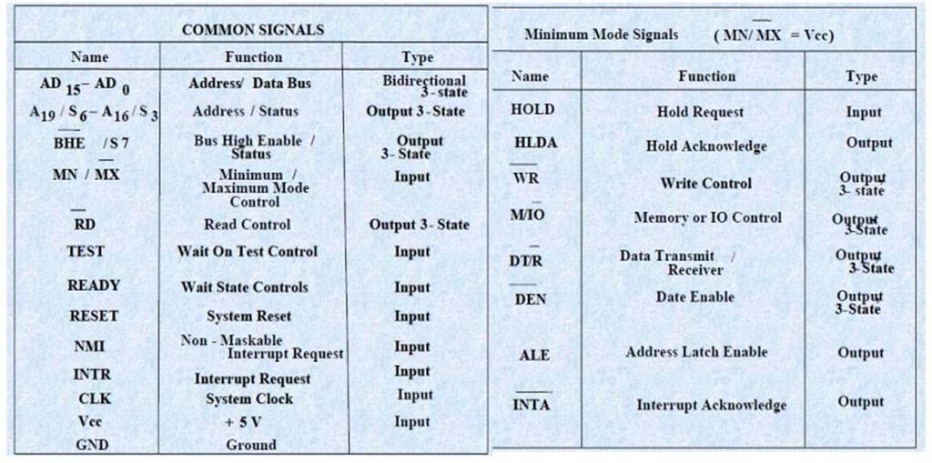
5 8086 Pins (Common Pins) AD15-AD0 (Address/Data Bus) and ALE (Address latch enable) The 8086 address/data bus lines compose the multiplexed address/data bus on the These lines contains address bits when ALE=1 and data bits when ALE=0. These pins enter a high-impedance state when a hold acknowledge occurs. ALE=1 ALE=0 AD15-AD0 act as address pins AD15-AD0 act as data pins A19/S6 A16/S3 (Address/ Status bus) Other 4 address lines (addresses are 20 bits) are the A16/S3, A17/S4, A18/S5 and A19/S6 (Multiplexed with status lines) During the first clock period of bus cycle (read or write cycle), the entire 20- bit address is available on these lines. During all other clock cycles for memory and I/O operations, AD15 AD0 contain the 16 bit data and S3, S4, S5 and S6 become status lines. S3 and S4 lines are decoded as follows(during memory operation): A17/S4 A16/S3 Function 0 0 Extra Segment 0 1 Stack Segment 1 0 Code or no segment 1 1 Data Segment During I/O operation: A18/S5 and A19/S6 will stay low during the first clock period. During all other cycles, A18/S5 indicates the status of the 8086 interrupt enable flag and A19/S6 become low, a low A19/S6 pin indicates that the 8086 is on the
6 8086 Pins (Common Pins) [Continued] RD (Read Signal) If RD =0, the data bus receives data from the memory or I/O devices. This pin floats to its high-impedance state during a hold acknowledge. READY If READY =0, the microprocessor enters into wait states and remains idle. If the READY pin=1, it has no effect on the operation of the microprocessor. The READY input is controlled to insert wait states into the timing of the microprocessor. TEST The TEST pin is an input that is tested by the WAIT instruction. If TEST is a logic 0, the wait instruction functions as a NOP and if TEST is logic 1, the wait instruction waits for TEST to become a logic zero. INTR Interrupt request is used to request a hardware interrupt. If INTR is held high when IF=1 the 8086 enters an interrupt acknowledge cycle (INTA becomes active) after the current instructions has completed execution. NMI The Non-maskable interrupt input is similar to INTR except that the NMI interrupt does not check to see whether the IF flag bit is a logic 1. If NMI is activated, this interrupt input uses interrupt vector 2.
7 8086 Pins (Common Pins) [Continued] RESET The RESET input causes the microprocessor to reset itself if this pin is held high for a minimum of four clocking period. It causes the 8086 to initialize register DS, SS, ES, IP and flags to all zeros and CS to FFFFH. CLK The CLK (clock) pin provides the basic timing signal to the microprocessor. The clock must have a duty cycle of 33% (high for one third of the clocking period and low for two thirds) to provide proper internal timing for the Vcc The power supply input provides a +5.0 V, ±10% signal to the microprocessor. GND The ground connection is the return for the power supply. Note that the 8086 microprocessors have two pins leveled GND- both must be connected to the ground for the proper operation. MN/MX The minimum/maximum mode pin selects either minimum mode or maximum mode operation for the microprocessor. If minimum mode is selected, the MN/MX pin must be connected directly to +5.0 V. BHE/S7 (Bus High Enable) The 8086 outputs a low on this pin during read, write and interrupt acknowledge cycles in which data are to be transferred in a high order byte (AD15-AD8) of the data bus. The state of S7 is always logic 1.
8 8086 Pins (Minimum Mode Pins) M/IO This pin selects memory or I/O. When the 8086 executes an I/O instruction such as IN or OUT, it outputs a LOW on M/IO. On the other hand, the 8086 outputs HIGH on the pin when it executes a memory reference instruction such as MOV AX, [SI]. WR When WR =0, the processor is performing a write memory or write I/O operation depending on the M/IO signal. INTA The interrupt acknowledge signal is a response to the INTR input pin. The INTA pin is normally used to gate the interrupt vector number onto the data bus in response to an interrupt request. ALE (Address latch enable) Used to multiplex the AD0-AD15 into A0-A15 (when ALE=1)and D0-D15 (when ALE=0).
9 8086 Pins (Minimum Mode Pins) [Continued] DT/R (Data Transmit/receive) The data transmit/receive signal shows that the microprocessor data bus is transmitting (DT/R=1) or receiving (DT/R = 0) data. The signal is used to enable external data bus buffers. DEN (Data bus enable) Data bus enable activates external data bus buffers. (e.g. Data bus buffer of 8255A) HOLD If the HOLD signal is a logic 1, the microprocessor stops executing software and places its address, data, and control bus at the high impedance state. If the HOLD pin is logic 0, the microprocessor executes software normally. HALDA (Hold Acknowledgement) Hold acknowledgement indicates that the 8086 has entered the hold state.
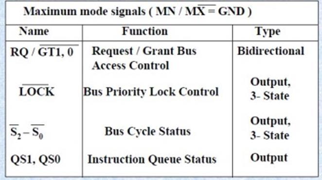
10 8086 Maximum Mode Pins S2, S1, and S0 The status bits indicate the function of the current bus cycle. These signals are normally decoded by the 8288 bus controller. Table shows the function of these three status bits in the maximum mode. S2 S1 S0 Function Interrupt acknowledge I/O Read I/O Write Halt Opcode Fetch Memory Read Memory write Passive RQ/GTI and RQ/GT0 The request/grant pins request direct memory accesses (DMA) during maximum mode operation. These lines are bidirectional and are used to both request and grant a DMA operation. [DMA: Direct memory access normally occurs between an I/O device and memory without the use of microprocessor. A DMA read transfers data from memory to the I/O device. A DMA write transfers data from an I/O device to memory]
11 8086 Maximum Mode Pins (Continued) LOCK The 8086 outputs LOW on the LOCK pin to prevent other bus masters from gaining control of the system bus. QS1 and QS0 The 8086 outputs to QS1 and QS0 pins to provide status to allow external tracking of the internal 8086 instruction queue as follows- QS1 QS0 Function 0 0 No operation 0 1 First byte of opcode from queue 1 0 Empty the queue 1 1 Subsequent byte from queue
12 Clock Generator (8284A) The 8284A provides the following basic functions or signals: Clock Generation. RESET synchronization. READY synchronization and A TTL level peripheral clock signal. Pin Functions: The 8284A is an 18-pin integrated circuit designed specially for use with the 8086/8088 microprocessor. The following is a list of each pin and its function. The address enable pins are provided to qualify the bus ready signals, RDY1 and RDY2, respectively. Wait states are generated by the READY pin of the 8088/8086 microprocessor, which is controlled by these two pins.
13 Clock Generator (8284A): Pin functions The bus ready inputs are provided from a device located on the system data bus, in conjunction with the, pins, to cause wait state in an 8086/8088- based system. Ready synchronization selection input selects either one or two stages of synchronization for the RDY1 and RDY2 inputs. When it is low, two stages of ready synchronization are provided. When it is high, a stage of ready synchronization is provided. READY is an output pin that connects to the 8086/8088 READY input. This signal is synchronized with the RDY1 and RDY2 inputs. The crystal oscillator pins connect to an external crystal used as the timing source for the clock generator and all its functions.
14 Clock Generator (8284A): Pin functions (Cont.) Frequency/Crystal select input chooses the clocking source for the 8284A. If this pin is high, clock is supplied from external source connected to EFI pin. If this pin is low, clock is supplied from crystal oscillator. External frequency input is an input pin to provide external clock pulse for the 8086/8088 microprocessor. The input external clock should be three times greater than the desired output clock. The clock output pin provides the CLK input signal to the 8086/8088 microprocessor and other components in the system. The CLK input has an output signal that is one-third of the crystal or EFI input frequency, and has a 33% duty cycle, which is required by the 8086/8088.
15 Clock Generator (8284A): Pin functions (Cont.) The peripheral clock signal is one-sixth the crystal or EFI input frequency, and has a 50% duty cycle. The PCLK output provides a clock signal to the peripheral equipment in the system. The oscillator output is a TTL-level signal that is at the same frequency as the crystal. The OSC output provides an EFI input to other 8284A clock generators in some multiple processor system. The reset input is an active low input to the 8284A which is used to generate RESET signal of microprocessor. The reset output is connected to the 8086/8088 RESET input pin. The clock synchronization pin is used whenever the EFI input provides synchronization in systems with multiple processor. If the internal crystal oscillator is used, this pin must be grounded. GND is connected to ground and Vcc to +5V with tolerance of ±10%
16 Operation of the 8254A
 Operation of the clock")
17 Operation of the 8254A (Cont.) Operation of the clock section:
 Operation of the reset")
18 Operation of the 8254A (Cont.) Operation of the reset section:
19 Operation of the 8254A (Cont.) Clock Generator Interfaced with 8086/8088 microprocessor
PIN DIAGRAM. Richa Upadhyay Prabhu. NMIMS s MPSTME January 19, 2016
 PIN DIAGRAM Richa Upadhyay Prabhu NMIMS s MPSTME richa.upadhyay@nmims.edu January 19, 2016 Richa Upadhyay Prabhu (MPSTME) 8080 Microprocessor January 19, 2016 1 / 51 Pin Diagram of 8086 Richa Upadhyay
Pin diagram Common SignalS Architecture: Sub: 8086 HARDWARE
 1 CHAPTER 6 HARDWARE ARCHITECTURE OF 8086 8086 Architecture: 6.1 8086 Pin diagram 8086 is a 40 pin DIP using CHMOS technology. It has 2 GND s as circuit complexity demands a large amount of current flowing
UMBC. 80C86/80C88: CMOS version draws 10mA with temp spec -40 to 225degF. 450mV while input max can be no higher than 800mV). 0 0.
. 0 0.") 8086/88 Device Specifications Both are packaged in DIP (Dual In-Line Packages). 8086: 16-bit microprocessor with a 16-bit data bus 8088: 16-bit microprocessor with an 8-bit data bus. Both are 5V parts:
8086/88 Device Specifications Both are packaged in DIP (Dual In-Line Packages). 8086: 16-bit microprocessor with a 16-bit data bus 8088: 16-bit microprocessor with an 8-bit data bus. Both are 5V parts:
EC 6504 Microprocessor and Microcontroller. Unit II System Bus Structure
 EC 6504 Microprocessor and Microcontroller Unit II 8086 System Bus Structure Syllabus: 8086 Signals Basic Configurations System bus timing System Design using 8086 IO Programming Introduction to multiprogramming
Overview of Intel 80x86 µp
 CE444 ١ ٢ 8088/808 µp and Supporting Chips Overview of Intel 80x8 µp ٢ ١ 8088/808 µp ٣ Both are mostly the same with small differences. Both are of bit internal Data bus Both have 0 bit address bus Capable
Microcomputer System Design
 Microcomputer System Design COE305 Lab. What is a Microprocessor? A microprocessor is a multipurpose, clockdriven, register-based electronic device that reads binary instructions from a storage device
UNIT II OVERVIEW MICROPROCESSORS AND MICROCONTROLLERS MATERIAL. Introduction to 8086 microprocessors. Architecture of 8086 processors
 OVERVIEW UNIT II Introduction to 8086 microprocessors Architecture of 8086 processors Register Organization of 8086 Memory Segmentation of 8086 Pin Diagram of 8086 Timing Diagrams for 8086 Interrupts of
SRI VIDYA COLLEGE OF ENGINEERING AND TECHNOLOGY,VIRUDHUNAGAR
 Year/sem: 02/04 Academic Year: 2014-2015 (even) UNIT II THE 8086 SYSTEM BUS STRUCTURE PART A 1. What are the three groups of signals in 8086? The 8086 signals are categorized in three groups. They are:
Pin Description, Status & Control Signals of 8085 Microprocessor
 Pin Description, Status & Control Signals of 8085 Microprocessor 1 Intel 8085 CPU Block Diagram 2 The 8085 Block Diagram Registers hold temporary data. Instruction register (IR) holds the currently executing
MICROPROCESSOR TECHNOLOGY
 MICROPROCESSOR TECHNOLOGY Assis. Prof. Hossam El-Din Moustafa Lecture 12 Ch.5 8086/8088 Hardware Specifications 22-Mar-15 1 The Buffered System If more than 10 unit loads are attached to any bus pin, the
9/25/ Software & Hardware Architecture
 8086 Software & Hardware Architecture 1 INTRODUCTION It is a multipurpose programmable clock drive register based integrated electronic device, that reads binary instructions from a storage device called
Instructions Involve a Segment Register (SR-field)
") BYTE 1 = 11000111 2 = C7 16 BYTE 2 = (MOD)000(R/M) = 100000112 = 83 16 BYTE 3 = 34 16 and BYTE 4 = 12 16 BYTE 5 = CD 16 and BYTE 6 = AB 16 The machine code for the instruction is: MOV [BP+DI+1234H], 0ABCDH
BYTE 1 = 11000111 2 = C7 16 BYTE 2 = (MOD)000(R/M) = 100000112 = 83 16 BYTE 3 = 34 16 and BYTE 4 = 12 16 BYTE 5 = CD 16 and BYTE 6 = AB 16 The machine code for the instruction is: MOV [BP+DI+1234H], 0ABCDH
UNIT-1. It is a 16-bit Microprocessor (μp).it s ALU, internal registers works with 16bit binary word.
.it s ALU, internal registers works with 16bit binary word.") UNIT-1 Introduction to 8086: 8086 Microprocessor is an enhanced version of 8085Microprocessor that was designed by Intel in 1976. It is a 16-bit Microprocessor having 20 address lines and16 data lines
UNIT-1 Introduction to 8086: 8086 Microprocessor is an enhanced version of 8085Microprocessor that was designed by Intel in 1976. It is a 16-bit Microprocessor having 20 address lines and16 data lines
EC 6504 MICROPROCESSOR AND MICROCONTROLLER Electronicsand Communication Engineering Fifth Semester UNIT-1I Part A 1. Definemachinecycle.
 EC 6504 MICROPROCESSOR AND MICROCONTROLLER Electronicsand Communication Engineering Fifth Semester UNIT-1I Part A 1. Definemachinecycle. [N/D 16] Machine cycle is defined as the time required to complete
 UNIT II SYSTEM BUS STRUCTURE 1. Differentiate between minimum and maximum mode 2. Give any four pin definitions for the minimum mode. 3. What are the pins that are used to indicate the type of transfer
UNIT 1. Introduction to microprocessor. Block diagram of simple computer or microcomputer.
 UNIT 1 Unit 1 contents at a glance: 1. Architecture of 8086 microprocessor, 2. Register organization, 3. 8086 flag register and its functions, 4. addressing modes of 8086, 5. Pin diagram of 8086, 6. Minimum
MICROPROCESSOR TECHNOLOGY
 MICROPROCESSOR TECHNOLOGY Assis. Prof. Hossam El-Din Moustafa Lecture 13 Ch.6 The 80186, 80188, and 80286 Microprocessors 21-Apr-15 1 Chapter Objectives Describe the hardware and software enhancements
Lecture 5: Computer Organization Instruction Execution. Computer Organization Block Diagram. Components. General Purpose Registers.
 Lecture 5: Computer Organization Instruction Execution Computer Organization Addressing Buses Fetch-Execute Cycle Computer Organization CPU Control Unit U Input Output Memory Components Control Unit fetches
1 MALP ( ) Unit-1. (1) Draw and explain the internal architecture of 8085.
 Unit-1. (1) Draw and explain the internal architecture of 8085.") (1) Draw and explain the internal architecture of 8085. The architecture of 8085 Microprocessor is shown in figure given below. The internal architecture of 8085 includes following section ALU-Arithmetic
(1) Draw and explain the internal architecture of 8085. The architecture of 8085 Microprocessor is shown in figure given below. The internal architecture of 8085 includes following section ALU-Arithmetic
UNIT-I. 1.Draw and explain the Architecture of a 8085 Microprocessor?
 UNIT-I INTRODUCTION TO MICROPROCESSOR A common way of categorizing microprocessors is by the no. of bits that their ALU can work with at a time. (i) The first commercially available microprocessor was
8088,80286 MICROPROCESSORS AND ISA BUS
 8088,80286 MICROPROCESSORS AND ISA BUS OBJECTIVES this chapter enables the student to: State the function of the pins of the 8088. List the functions of the 8088 data, address, and control buses. State
Topic 2 :16 Bit Microprocessor: 8086 (24 Marks)
") Topic 2 :16 Bit Microprocessor: 8086 (24 Marks) Features of 8086 8086 is a 16 bit processor. It s ALU, internal registers works with 16bit binary word 8086 has a 16bit data bus. It can read or write data
Topic 2 :16 Bit Microprocessor: 8086 (24 Marks) Features of 8086 8086 is a 16 bit processor. It s ALU, internal registers works with 16bit binary word 8086 has a 16bit data bus. It can read or write data
Chapter NINE 8088,80286 MICROPROCESSORS AND ISA BUS
 Chapter NINE 8088,80286 MICROPROCESSORS AND ISA BUS OBJECTIVES this chapter enables the student to: State the function of the pins of the 8088. List the functions of the 8088 data, address, and control
ELE 3230 Microprocessors and Computer Systems
 ELE 3230 Microprocessors and Computer Systems Chapter 4 8088 System Architecture (*Hall:ch2; Brey:ch1; Triebel:ch2) ELE 3230 - Chapter 4 1 Historical Background 1969/70 Intel 4004, first Microprocessor
LECTURE NOTES MICROPROCESSORS AND INTERFACING DEVICES
 LECTURE NOTES ON MICROPROCESSORS AND INTERFACING DEVICES III B. Tech II semester (JNTUH-R15) Mr.R Mahendhar Reddy, Associate Professor, ECE ELECTRICAL AND ELECTRONICS ENGINEERING INSTITUTE OF AERONAUTICAL
1. INTRODUCTION TO MICROPROCESSOR AND MICROCOMPUTER ARCHITECTURE:
 1. INTRODUCTION TO MICROPROCESSOR AND MICROCOMPUTER ARCHITECTURE: A microprocessor is a programmable electronics chip that has computing and decision making capabilities similar to central processing unit
8086 PIN Diagram Signals with common functions in both Modes: The following signal description is common for both the minimum and maximum modes.
 UNIT II - 8086 SYSTEM BUS STRUCTURE 8086 signals Basic configurations System bus timing System design using 8086 IO programming Introduction to Multiprogramming System Bus Structure Multiprocessor configurations
The 8086 Microprocessor
 The 8086 Microprocessor 1. Draw the pin diagram of 8086. Ans. There would be two pin diagrams one for MIN mode and the other for MAX mode of 8086, shown in Figs. 11.1 and 11.2 respectively. The pins that
1. state the priority of interrupts of Draw and explain MSW format of List salient features of
 Q.1) 1. state the priority of interrupts of 80286. Ans- 1. Instruction exceptions 2. Single step 3. NMI 4. Processor extension segment overrun 5. INTR 6. INT 2. Draw and explain MSW format of 80286. Ans-
PAPER SOLUTION. Microprocessor & Microcontroller SESSIONAL 1
 PPER SOLUTION SESSIONL 1 Microprocessor & Microcontroller - 2017-18 Department of Electronics & Telecommunication Engineering ST. VINCENT PLLOTTI COLLEGE OF ENGINEERING & TECHNOLOGY Q.1 (a) Draw and explain
The Purpose of Interrupt
 Interrupts 3 Introduction In this chapter, the coverage of basic I/O and programmable peripheral interfaces is expanded by examining a technique called interrupt-processed I/O. An interrupt is a hardware-initiated
Chapter 8 Summary: The 8086 Microprocessor and its Memory and Input/Output Interface
 Chapter 8 Summary: The 8086 Microprocessor and its Memory and Input/Output Interface Figure 1-5 Intel Corporation s 8086 Microprocessor. The 8086, announced in 1978, was the first 16-bit microprocessor
Microprocessor Architecture
 Microprocessor - 8085 Architecture 8085 is pronounced as "eighty-eighty-five" microprocessor. It is an 8-bit microprocessor designed by Intel in 1977 using NMOS technology. It has the following configuration
Chapter 1: Basics of Microprocessor [08 M]
![Chapter 1: Basics of Microprocessor [08 M]](/thumbs/77/75860546.jpg "Chapter 1: Basics of Microprocessor [08 M]") Microprocessor: Chapter 1: Basics of Microprocessor [08 M] It is a semiconductor device consisting of electronic logic circuits manufactured by using either a Large scale (LSI) or Very Large Scale (VLSI)
Microprocessor: Chapter 1: Basics of Microprocessor [08 M] It is a semiconductor device consisting of electronic logic circuits manufactured by using either a Large scale (LSI) or Very Large Scale (VLSI)
Program controlled semiconductor device (IC) which fetches (from memory), decodes and executes instructions.
 which fetches (from memory), decodes and executes instructions.") 8086 Microprocessor Microprocessor Program controlled semiconductor device (IC) which fetches (from memory), decodes and executes instructions. It is used as CPU (Central Processing Unit) in computers.
8086 Microprocessor Microprocessor Program controlled semiconductor device (IC) which fetches (from memory), decodes and executes instructions. It is used as CPU (Central Processing Unit) in computers.
1. Internal Architecture of 8085 Microprocessor
 1. Internal Architecture of 8085 Microprocessor Control Unit Generates signals within up to carry out the instruction, which has been decoded. In reality causes certain connections between blocks of the
2. List the five interrupt pins available in INTR, TRAP, RST 7.5, RST 6.5, RST 5.5.
 DHANALAKSHMI COLLEGE OF ENGINEERING DEPARTMENT OF ELECTRICAL AND ELECTRONICS ENGINEERING EE6502- MICROPROCESSORS AND MICROCONTROLLERS UNIT I: 8085 PROCESSOR PART A 1. What is the need for ALE signal in
MP Assignment III. 1. An 8255A installed in a system has system base address E0D0H.
 MP Assignment III 1. An 8255A installed in a system has system base address E0D0H. i) Calculate the system addresses for the three ports and control register for this 8255A. System base address = E0D0H
Overview. M. Krishna Kumar MM/M4/LU10/V1/2004 1
 Overview Each processor in the 80x86 family has a corresponding coprocessor with which it is compatible Math Coprocessor is known as NPX,NDP,FUP. Numeric processor extension (NPX), Numeric data processor
CHAPTER 5 : Introduction to Intel 8085 Microprocessor Hardware BENG 2223 MICROPROCESSOR TECHNOLOGY
 CHAPTER 5 : Introduction to Intel 8085 Hardware BENG 2223 MICROPROCESSOR TECHNOLOGY The 8085A(commonly known as the 8085) : Was first introduced in March 1976 is an 8-bit microprocessor with 16-bit address
Department of Computer Science and Engineering
 Department of Computer Science and Engineering QUESTION BANK Subcode/Subject : CS1304 Microprocessor & Microcontroller Year/Sem: III / V UNIT I THE 8085 MICROPROCESSOR PART A ( 2Marks) 1. How AD0-AD7 are
Features. PART NUMBER PART MARKING TEMP. RANGE ( C) PACKAGE PKG. DWG. # CP80C86-2Z (Note 1) CP80C86-2Z 0 to Ld PDIP (Note 2) (RoHS compliant)
 PACKAGE PKG. DWG. # CP80C86-2Z (Note 1) CP80C86-2Z 0 to Ld PDIP (Note 2) (RoHS compliant)") DATASHEET CMOS 16-Bit Microprocessor The high performance 16-bit CMOS CPU is manufactured using a self-aligned silicon gate CMOS process (Scaled SAJI IV). Two modes of operation, minimum for small systems
DATASHEET CMOS 16-Bit Microprocessor The high performance 16-bit CMOS CPU is manufactured using a self-aligned silicon gate CMOS process (Scaled SAJI IV). Two modes of operation, minimum for small systems
History and Basic Processor Architecture
 History and Basic Processor Architecture History of Computers Module 1 Section 1 What Is a Computer? An electronic machine, operating under the control of instructions stored in its own memory, that can
For more notes of DAE
 Created by ARSLAN AHMED SHAAD ( 1163135 ) AND MUHMMAD BILAL ( 1163122 ) VISIT : www.vbforstudent.com Also visit : www.techo786.wordpress.com For more notes of DAE CHAPTER #6 Intel 8088/86 System Timing
II/IV B.Tech (Regular/Supplementary) DEGREE EXAMINATION. Microprocessors and Microcontrollers. Answer ONE question from each unit.
 DEGREE EXAMINATION. Microprocessors and Microcontrollers. Answer ONE question from each unit.") Hall Ticket Number: 14 CS/IT 503 November, 2017 Fifth Semester Time: Three Hours Answer Question No.1 compulsorily. Answer ONE question from each unit. II/IV B.Tech (Regular/Supplementary) DEGREE EXAMINATION
Hall Ticket Number: 14 CS/IT 503 November, 2017 Fifth Semester Time: Three Hours Answer Question No.1 compulsorily. Answer ONE question from each unit. II/IV B.Tech (Regular/Supplementary) DEGREE EXAMINATION
MICROPROCESSOR MICROPROCESSOR. From the above description, we can draw the following block diagram to represent a microprocessor based system: Output
 8085 SATISH CHANDRA What is a Microprocessor? The word comes from the combination micro and processor. Processor means a device that processes whatever. In this context, processor means a device that processes
MICROPROCESSOR AND MICROCONTROLLER BASED SYSTEMS
 MICROPROCESSOR AND MICROCONTROLLER BASED SYSTEMS UNIT I INTRODUCTION TO 8085 8085 Microprocessor - Architecture and its operation, Concept of instruction execution and timing diagrams, fundamentals of
Features. PART NUMBER PART MARKING TEMPERATURE RANGE ( C) PACKAGE PKG. DWG. # MD80C88-2/883 MD80C88-2/ to LD CERDIP F40.
 PACKAGE PKG. DWG. # MD80C88-2/883 MD80C88-2/ to LD CERDIP F40.") DATASHEET 80C88/883 CMOS 8-/16-Bit Microprocessor The Intersil 80C88/883 high performance 8-/16-bit CMOS CPU is manufactured using a self-aligned silicon gate CMOS process (Scaled SAJI IV). Two modes of
DATASHEET 80C88/883 CMOS 8-/16-Bit Microprocessor The Intersil 80C88/883 high performance 8-/16-bit CMOS CPU is manufactured using a self-aligned silicon gate CMOS process (Scaled SAJI IV). Two modes of
Basics of Microprocessor
 Unit 1 Basics of Microprocessor 1. Microprocessor Microprocessor is a multipurpose programmable integrated device that has computing and decision making capability. This semiconductor IC is manufactured
80C88. CMOS 8/16-Bit Microprocessor. Description. Features. Ordering Information FN July 2004
 July 2004 Features Compatible with NMOS 8088 Direct Software Compatibility with 80C86, 8086, 8088 8-Bit Data Bus Interface; 16-Bit Internal Architecture Completely Static CMOS Design - DC.............................
Unit I Introduction. Department of Electronics and Communication Engineering VARDHAMAN COLLEGE OF ENGINEERING Shamshabad, Hyderabad , India.
 Unit I Introduction Department of Electronics and Communication Engineering VARDHAMAN COLLEGE OF ENGINEERING Shamshabad, Hyderabad 501218, India. Pre-requisites Digital Logic Design (A1404) Computer Architecture
These three counters can be programmed for either binary or BCD count.
 S5 KTU 1 PROGRAMMABLE TIMER 8254/8253 The Intel 8253 and 8254 are Programmable Interval Timers (PTIs) designed for microprocessors to perform timing and counting functions using three 16-bit registers.
Northern India Engineering College, Delhi (GGSIP University) PAPER I
 PAPER I") PAPER I Q1.Explain IVT? ANS. interrupt vector table is a memory space for storing starting addresses of all the interrupt service routine. It stores CS:IP PAIR corresponding to each ISR. An interrupt vector
PAPER I Q1.Explain IVT? ANS. interrupt vector table is a memory space for storing starting addresses of all the interrupt service routine. It stores CS:IP PAIR corresponding to each ISR. An interrupt vector
Handout 15. by Dr Sheikh Sharif Iqbal. Memory Interface of 8088 and 8086 processors
 Handout 15 Ref: Online course on EE-390, KFUPM Objective: by Dr Sheikh Sharif Iqbal Memory Interface of 8088 and 8086 processors - To introduce the read and write bus cycles of the 8088 and 8086 processors.
CHETTINAD COLLEGE OF ENGINEERING AND TECHNOLOGY COMMUNICATION ENGINEERING REG 2008 TWO MARKS QUESTION AND ANSWERS
 CHETTINAD COLLEGE OF ENGINEERING AND TECHNOLOGY B.E.,/B.TECH., ELECTRONICS EC6504 MICROPROCESSORS & MICRO CONTROLLERS COMMUNICATION ENGINEERING REG 2008 TWO MARKS QUESTION AND ANSWERS UNIT 1 AND 2 CS SUBJECT
Architecture of 8085 microprocessor
 Architecture of 8085 microprocessor 8085 consists of various units and each unit performs its own functions. The various units of a microprocessor are listed below Accumulator Arithmetic and logic Unit
Lecture 6: memory structure 8086 Outline: 1.introduction 2.memory reserve 3.bus operation
 Lecture 6: memory structure 8086 Outline: 1.introduction 2.memory reserve 3.bus operation 1 1.INRTODUCTION The 8086 memory is a sequence of up to 1 million 8-bit bytes, a considerable increase over the
Chapter 13 Direct Memory Access and DMA-Controlled I/O
 Chapter 13 Direct Memory Access and DMA-Controlled I/O The DMA I/O technique provides direct access to the memory while the microprocessor is temporarily disabled This allows data to be transferred between
BASIC INTERRUPT PROCESSING
 Interrupts BASIC INTERRUPT PROCESSING This section discusses the function of an interrupt in a microprocessor-based system. Structure and features of interrupts available to Intel microprocessors. The
Chapter 4 : Microprocessor System
 Chapter-4 Microprocessor System A microcomputer consists of a set of components or modules of three basic types CPU memory and I/O units which communicate with each other. PIN Configuration of 8085 Fig
eaymanelshenawy.wordpress.com
 Lectures on Memory Interface Designed and Presented by Dr. Ayman Elshenawy Elsefy Dept. of Systems & Computer Eng.. Al-Azhar University Email : eaymanelshenawy@yahoo.com eaymanelshenawy.wordpress.com Chapter
QUESTION BANK. EE 6502 / Microprocessor and Microcontroller. Unit I Processor. PART-A (2-Marks)
") QUESTION BANK EE 6502 / Microprocessor and Microcontroller Unit I- 8085 Processor PART-A (2-Marks) YEAR/SEM : III/V 1. What is meant by Level triggered interrupt? Which are the interrupts in 8085 level
QUESTION BANK EE 6502 / Microprocessor and Microcontroller Unit I- 8085 Processor PART-A (2-Marks) YEAR/SEM : III/V 1. What is meant by Level triggered interrupt? Which are the interrupts in 8085 level
Design with Microprocessors
 Design with Microprocessors Year III Computer Science 1-st Semester Lecture 11: I/O transfer with x86 I/O Transfer I/O Instructions We discussed IN, OUT, INS and OUTS as instructions for the transfer of
Description. SMD# -55 o C to +125 o C QA QA F40.6 CLCC -55 o C to +125 o C MR80C86/B MR80C86-
 TM 80C86 March 1997 Features Compatible with NMOS 8086 Completely Static CMOS Design - DC............................. 5MHz (80C86) - DC............................ 8MHz (80C86-2) Low Power Operation -
Microprocessor s. Address Bus. External Buses. Interfacing CPU with external word. We classify the CPU interfacing signals in three functional buses:
 Interfacing CPU with external word s interfacing signals bus bus Power supply lines a d Typical Bus arbitration Status Bus control Interrupts control Control bus Clock signal Miscellaneous External Buses
Computer Organization. Submitted By: Dalvir Hooda
 Computer Organization Submitted By: Dalvir Hooda 3 Fundamental Components of Computer The CPU (ALU, Control Unit, Registers) The Memory Subsystem (Stored Data) The I/O subsystem (I/O devices) CPU Address
MATH CO-PROCESSOR 8087
 MATH CO-PROCESSOR 8087 1 Gursharan Singh Tatla professorgstatla@gmail.com INTRODUCTION 8087 was the first math coprocessor for 16-bit processors designed by Intel. It was built to pair with 8086 and 8088.
Unit DMA CONTROLLER 8257
 DMA CONTROLLER 8257 In microprocessor based system, data transfer can be controlled by either software or hardware. To transfer data microprocessor has to do the following tasks: Fetch the instruction
8086 INTERNAL ARCHITECTURE
 8086 INTERNAL ARCHITECTURE Segment 2 Intel 8086 Microprocessor The 8086 CPU is divided into two independent functional parts: a) The Bus interface unit (BIU) b) Execution Unit (EU) Dividing the work between
PESIT Bangalore South Campus
 INTERNAL ASSESSMENT TEST 2 Date : 28/03/2016 Max Marks: 50 Subject & Code : Microprocessor (10CS45) Section: IV A and B Name of faculty: Deepti.C Time: 8:30-10:00 am Note: Answer any complete five questions
MAHALAKSHMI ENGINEERING COLLEGE TIRUCHIRAPALLI UNIT I THE 8085 & 8086 MICROPROCESSORS. PART A (2 Marks)
") MAHALAKSHMI ENGINEERING COLLEGE TIRUCHIRAPALLI-621213. UNIT I THE 8085 & 8086 MICROPROCESSORS PART A (2 Marks) 1. Give the significance of SIM and RIM instruction available in 8085. [NOV/DEC 2006] Instruction
MAHALAKSHMI ENGINEERING COLLEGE TIRUCHIRAPALLI-621213. UNIT I THE 8085 & 8086 MICROPROCESSORS PART A (2 Marks) 1. Give the significance of SIM and RIM instruction available in 8085. [NOV/DEC 2006] Instruction
DATASHEET HS-80C86RH. Features. Ordering Information. Radiation Hardened 16-Bit CMOS Microprocessor. FN3035 Rev 0.00 Page 1 of 30.
 DATASHEET HS-80C86RH Radiation Hardened 16-Bit CMOS Microprocessor The Intersil HS-80C86RH high performance radiation hardened 16-bit CMOS CPU is manufactured using a hardened field, self aligned silicon
8254 is a programmable interval timer. Which is widely used in clock driven digital circuits. with out timer there will not be proper synchronization
 8254 is a programmable interval timer. Which is widely used in clock driven digital circuits. with out timer there will not be proper synchronization between two devices. So it is very useful chip. The
32- bit Microprocessor-Intel 80386
 32- bit Microprocessor-Intel 80386 30 Marks Course Outcome: Explain memory management and concept of pipelining. Describe the concept of paging and addressing. Signal Description of 80386 Signal Descriptions
Segment A Programmable Peripheral Interface (PPI)
") Segment 6 8255A Programmable Peripheral Interface (PPI) Content Why 8255A? Handshaking and Handshaking Signal Parallel Data Transfer 8255A Internal Block Diagram Description of 8255A Internal Block Diagram
Segment 6 8255A Programmable Peripheral Interface (PPI) Content Why 8255A? Handshaking and Handshaking Signal Parallel Data Transfer 8255A Internal Block Diagram Description of 8255A Internal Block Diagram
Introduction to Microprocessor
 Introduction to Microprocessor The microprocessor is a general purpose programmable logic device. It is the brain of the computer and it performs all the computational tasks, calculations data processing
EEE3410 Microcontroller Applications Department of Electrical Engineering Lecture 4 The 8051 Architecture
 Department of Electrical Engineering Lecture 4 The 8051 Architecture 1 In this Lecture Overview General physical & operational features Block diagram Pin assignments Logic symbol Hardware description Pin
MICROPROCESSORS & MICRO CONTROLLER COLLEGE OF ENGINEERING DEPARTMENT OF COMPUTER SCIENCE AND ENGINEERING QUESTION BANK
 KINGS COLLEGE OF ENGINEERING DEPARTMENT OF COMPUTER SCIENCE AND ENGINEERING QUESTION BANK SUBJECT CODE: EC1257 SUBJECT NAME: MICROPROCESSOR AND MICROCONTROLLER YEAR : II IT SEM : IV UNIT I THE 8085 MICROPROCESSOR
Understanding the basic building blocks of a microcontroller device in general. Knows the terminologies like embedded and external memory devices,
 Understanding the basic building blocks of a microcontroller device in general. Knows the terminologies like embedded and external memory devices, CISC and RISC processors etc. Knows the architecture and
Control Unit: The control unit provides the necessary timing and control Microprocessor resembles a CPU exactly.
 Unit I 8085 and 8086 PROCESSOR Introduction to microprocessor A microprocessor is a clock-driven semiconductor device consisting of electronic logic circuits manufactured by using either a large-scale
EC6504 MICROPROCESSOR AND MICROCONTROLLER
 UNIT I THE 8086 MICROPROCESSOR 1. What do you mean by Addressing modes? (May/June 2014) The different ways that a microprocessor can access data are referred to as addressing modes. 2. What is meant by
3. The MC6802 MICROPROCESSOR
 3. The MC6802 MICROPROCESSOR This chapter provides hardware detail on the Motorola MC6802 microprocessor to enable the reader to use of this microprocessor. It is important to learn the operation and interfacing
The higher the values of above, the more powerful the CPU. Microprocessors are categorized in additional as: RISC or CISC.
 MICROPROCESSOR: A silicon chip that contains a CPU. A microprocessor (sometimes abbreviated μp) is a digital electronic component with miniaturized transistors on a single semiconductor integrated circuit
UNIT PROCESSORS:
 SYLLABUS PART - A UNIT 1 8086 PROCESSORS: Historical background, The microprocessor-based personal computer system, 8086 CPU Architecture, Machine language instructions, Instruction execution timing. (6Hours)
DEPARTMENT OF ECE QUESTION BANK SUBJECT: MICROPROCESSOR AND MICROCONTROLLER UNIT-1 PART-A (2 MARKS)
") DEPARTMENT OF ECE QUESTION BANK SUBJECT: MICROPROCESSOR AND MICROCONTROLLER CODE: EC6504 UNIT-1 1. How many memory locations are available in 8086 microprocessor? 2. What are the flags available in 8086
DEPARTMENT OF ECE QUESTION BANK SUBJECT: MICROPROCESSOR AND MICROCONTROLLER CODE: EC6504 UNIT-1 1. How many memory locations are available in 8086 microprocessor? 2. What are the flags available in 8086
INTERFACING THE ISCC TO THE AND 8086
 APPLICATION NOTE INTERFACING THE ISCC TO THE 68 AND 886 INTRODUCTION The ISCC uses its flexible bus to interface with a variety of microprocessors and microcontrollers; included are the 68 and 886. The
MICROPROCESSOR ALL IN ONE. Prof. P. C. Patil UOP S.E.COMP (SEM-II)
") MICROPROCESSOR UOP S.E.COMP (SEM-II) 80386 ALL IN ONE Prof. P. C. Patil Department of Computer Engg Sandip Institute of Engineering & Management Nashik pc.patil@siem.org.in 1 Architecture of 80386 2 ARCHITECTURE
MICROPROCESSOR UOP S.E.COMP (SEM-II) 80386 ALL IN ONE Prof. P. C. Patil Department of Computer Engg Sandip Institute of Engineering & Management Nashik pc.patil@siem.org.in 1 Architecture of 80386 2 ARCHITECTURE
PIO 8255 (cont..) M Krishna kumar MAM/M3/LU9e/V1/2004 1
 M Krishna kumar MAM/M3/LU9e/V1/2004 1") PIO 8255 (cont..) The parallel input-output port chip 8255 is also called as programmable peripheral input-output port. The Intel s 8255 is designed for use with Intel s 8-bit, 16-bit and higher capability
PIO 8255 (cont..) The parallel input-output port chip 8255 is also called as programmable peripheral input-output port. The Intel s 8255 is designed for use with Intel s 8-bit, 16-bit and higher capability
8/26/2010. Introduction to 8085 BLOCK DIAGRAM OF INTEL Introduction to Introduction to Three Units of 8085
 BLOCK DIAGRAM OF INTEL 8085 GURSHARAN SINGH TATLA Introduction to 8085 It was introduced in 1977. It is 8-bit microprocessor. Its actual name is 8085 A. It is single NMOS device. It contains 6200 transistors
Module 2. Embedded Processors and Memory. Version 2 EE IIT, Kharagpur 1
 Module 2 Embedded Processors and Memory Version 2 EE IIT, Kharagpur 1 Lesson 11 Embedded Processors - II Version 2 EE IIT, Kharagpur 2 Signals of a Typical Microcontroller In this lesson the student will
UMBC. contain new IP while 4th and 5th bytes contain CS. CALL BX and CALL [BX] versions also exist. contain displacement added to IP.
![UMBC. contain new IP while 4th and 5th bytes contain CS. CALL BX and CALL [BX] versions also exist. contain displacement added to IP.](/thumbs/74/70839578.jpg "UMBC. contain new IP while 4th and 5th bytes contain CS. CALL BX and CALL [BX] versions also exist. contain displacement added to IP.") Procedures: CALL: Pushes the address of the instruction following the CALL instruction onto the stack. RET: Pops the address. SUM PROC NEAR USES BX CX DX ADD AX, BX ADD AX, CX MOV AX, DX RET SUM ENDP NEAR
Procedures: CALL: Pushes the address of the instruction following the CALL instruction onto the stack. RET: Pops the address. SUM PROC NEAR USES BX CX DX ADD AX, BX ADD AX, CX MOV AX, DX RET SUM ENDP NEAR
Module 3. Embedded Systems I/O. Version 2 EE IIT, Kharagpur 1
 Module 3 Embedded Systems I/O Version 2 EE IIT, Kharagpur 1 Lesson 15 Interrupts Version 2 EE IIT, Kharagpur 2 Instructional Objectives After going through this lesson the student would learn Interrupts
12-Dec-11. Gursharan Singh Maninder Kaur. Introduction to 8085 BLOCK DIAGRAM OF INTEL Introduction to Introduction to 8085
 mailme@gursharansingh.in BLOCK DIAGRAM OF INTEL 8085 mailme@maninderkaur.in Introduction to 8085 It was introduced in 1977. It is 8-bit microprocessor. Its actual name is 8085 A. It is single NMOS device.
Lecture Note On Microprocessor and Microcontroller Theory and Applications
 Lecture Note On Microprocessor and Microcontroller Theory and Applications MODULE: 1 1. INTRODUCTION TO MICROPROCESSOR AND MICROCOMPUTER ARCHITECTURE: A microprocessor is a programmable electronics chip
Address connections Data connections Selection connections
 Interface (cont..) We have four common types of memory: Read only memory ( ROM ) Flash memory ( EEPROM ) Static Random access memory ( SARAM ) Dynamic Random access memory ( DRAM ). Pin connections common
MICROPROCESSOR TECHNOLOGY
 MICROPROCESSOR TECHNOLOGY Assis. Prof. Hossam El-Din Moustafa Lecture 16 Ch.7 The 80386 and 80486 Microprocessors 21-Apr-15 1 System Descriptors The system descriptor defines information about the system
Basic characteristics & features of 8086 Microprocessor Dr. M. Hebaishy
 Basic characteristics & features of 8086 Microprocessor Dr. M. Hebaishy Digital Logic Design Ch1-1 8086 Microprocessor Features: The 8086 microprocessor is a 16 bit microprocessor. The term 16 bit means
Microprocessors and Microcontrollers (EE-231)
") Microprocessors and Microcontrollers (EE-231) Main Objectives 8088 and 80188 8-bit Memory Interface 8086 t0 80386SX 16-bit Memory Interface I/O Interfacing I/O Address Decoding More on Address Decoding
Microprocessors and Microcontrollers (EE-231) Main Objectives 8088 and 80188 8-bit Memory Interface 8086 t0 80386SX 16-bit Memory Interface I/O Interfacing I/O Address Decoding More on Address Decoding
Digital System Design
 Digital System Design by Dr. Lesley Shannon Email: lshannon@ensc.sfu.ca Course Website: http://www.ensc.sfu.ca/~lshannon/courses/ensc350 Simon Fraser University i Slide Set: 15 Date: March 30, 2009 Slide
MICROPROCESSOR PROGRAMMING AND SYSTEM DESIGN
 MICROPROCESSOR PROGRAMMING AND SYSTEM DESIGN ROAD MAP SDK-86 Intel 8086 Features 8086 Block Diagram 8086 Architecture Bus Interface Unit Execution Unit 8086 Architecture 8086 Programmer s Model Flag Register