2214 EVENT LOGGER MODULE FOR THE VX2200 SYSTEM
|
|
|
- Brian Charles
- 5 years ago
- Views:
Transcription


1 2214 EVENT LOGGER MODULE FOR THE VX2200 SYSTEM
2 CONTENTS PAGE Manual Introduction 3 Product Overview 3 Operation and Connection 3 RS232 Connection 3-4 RS485 Connection PCB layout 5 RS485 Bus Terminal Jumper Setting 5 RS485/RS232 Switch Setting 5 Terminal Connections 5 Dip-Switch Settings 6-7 Technical Specification 7 Software Installation 8 Event Logger Software Set Up 8 Hardware Set Up 8 Launching the Software for the First Time 9 The Main Event Logger Screen 10 System Set Up Screen 11 Search Screen 14 Connect Function 18 Download Function 18 Delete Function 19 Activate Relay Function 20 About 20 Installation 21 Initial Installation Checks 21 Lock Release Wiring and Back EMF Protection 21 Push to Exit Connection 21 Wiring Diagrams RS232 Diagram 22 RS485 Diagram 23 Trouble Shooting 24 Additional Software Installation Note 25 Quick Software Setup Guide 25 Quick Hardware Reset & Setup Guide 25 Notes 26 Software Updates 27 Firmware Updates 27 Page 2
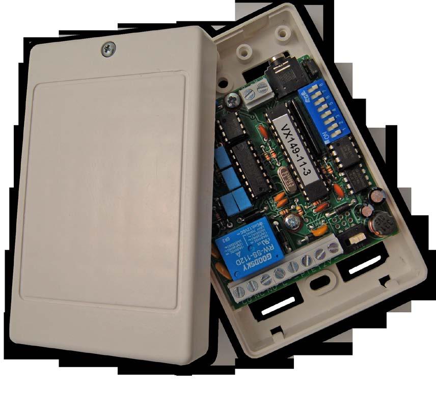
3 MANUAL INTRODUCTION The information in this manual is intended as an installation and commissioning guide for the 2214 event logger module. This manual should be read carefully before the installation commences. Any damage caused to the equipment due to faulty installations where the information in this manual has not been followed is not the responsibility of Videx Security Ltd. VIDEX run free training courses for engineers who have not installed this system before. Technical help is also available on during office hours or via An electronic copy of this user manual is available for download by scanning the QR code to the right. PRODUCT OVERVIEW The 2214 event logger module is designed for use with the VX2200 system and the VX2200 event logger software (version ). The 2214 connects between the two wire bus and a laptop or PC (via an Art.481) and records the events such as who is being called, when a conversation has taken place and who is opening the door. For higher security applications including installations in compliance with Secure By Design the 2214 also includes a remote relay and push to exit button input (as found on the 2213 remote relay) which enables it to be installed in a secure location away from the entrance. Another feature of the 2214 is that it can store up to 4000 events whilst offline, however when it is connected online in real time the events are unlimited. The 2214 event logger software also includes a caller display feature whereby information regarding the call is shown in real time when the call is made. The information that is displayed during a call is the flat/apartment being called, the name of the person or area being called and the entrance/area where the call was made from (refer to page 10). OPERATION AND CONNECTION Up to sixteen 2214 devices can be setup on any 2200 digital bus system. The 2214 device number (from device 0 to 15) can be set using dip switches 1-4 (also refer to page 6 for dip-switch settings). The 2214 is programmed using the event logger software and is connected to a PC or laptop via an Art.481 RS232/RS485 converter. The connection from the Art.481 RS232/RS485 converter to the 2214 device can be made using either the RS232 connection or by using the RS485 terminal connections but not both. RS232 Connection If only a single 2214 module is required on the system bus then it can be connected using a USB cable between the PC or laptop (using an Art.481 RS232/RS485 converter set up in RS232 mode) to the RS mm jack plug connection on the 2214 module. Fig.1 shows an example of an RS232 connection for a 1 entrance system. RS485 Connection If multipe 2214 modules are connected onto the system bus then they should be connected using a USB cable between the PC or laptop (using an Art.481 RS232/RS485 converter set up in RS485 mode) to the RS485 terminal connections on the first 2214 module in line and then an RS485 cable between subsequent 2214 modules. Fig.2 shows an example of an RS485 connection for a 1 entrance system with two 2214 modules monitoring the bus on two different legs of the system bus. Page 3
4 RS232 Connection Fig.1 RS485 Connection Fig.2 Page 4
 terminal connections (see description below).")

.")


5 2214 PCB LAYOUT RS485 bus (A,B) terminal connections (see description below). 2. RS mm jack plug connection. 3. RS485 bus termination jumper way dip-switch software chip. 6. RS485/RS232 switch way terminal connections (see description below). RS485 Bus Termination Jumper Setting Position A = RS485 termination closed. RS485/RS232 Switch Setting Switch away from the terminal block = RS485 Position B = RS485 termination open. Switch towards the terminal block = RS232 TERMINAL CONNECTIONS Connection Description CO Common connection of the relay NC Normally closed connection of the relay NO Normally open connection of the relay L Bus connection - Bus ground connection PTE Push to exit input (short to ground to activate) 12V 12V-14Vdc from power supply - 0V input from power supply A B RS485 bus connections Page 5
6 DIP-SWITCH SETTINGS Dip-switches SW1 to SW4 sets up the device number of the 2214 module (from 0 to 15). Setting Device Number Device Number SW1 SW2 SW3 SW4 Switch position 0 OFF OFF OFF OFF 1 ON OFF OFF OFF 2 OFF ON OFF OFF 3 ON ON OFF OFF 4 OFF OFF ON OFF 5 ON OFF ON OFF 6 OFF ON ON OFF 7 ON ON ON OFF 8 OFF OFF OFF ON 9 ON OFF OFF ON 10 OFF ON OFF ON 11 ON ON OFF ON 12 OFF OFF ON ON 13 ON OFF ON ON 14 OFF ON ON ON 15 ON ON ON ON SW1 to SW4 Page 6

7 Dip-switches SW5 and SW6 sets up the relay time of the 2214 module. SW5 and SW6 Setting Relay Time Relay Time SW5 SW6 Switch position 1 second OFF OFF 2 seconds ON OFF 4 seconds OFF ON 6 seconds ON ON Dip-switch SW7 sets up the data transfer of the 2214 module Data Transfer (1 door system only) Description SW7 Switch position 2214 module automatically sends data 2214 module sends data on request from software ON OFF SW7 Dip-switch SW8 sets up the 2214 module for use on a 1 level or 2 level system Data Transfer (1 door system) Description SW8 Switch position 1 level system operation OFF 2 level system operation ON SW8 Input Voltage Current (standby) TECHNICAL SPECIFICATION Current (during relay activation) PTE input open voltage PTE input closed voltage Bus voltage Maximum bus cable resistance Relay Contacts Enclosure material Enclosure dimensions 12V - 14Vdc Page 7 9mA 45-50mA 5Vdc 0Vdc 8Vdc 7Ω 24Vdc 120Vac 250Vac ABS plastic (white) 110mm (L) x 70mm (W) x 30mm (D)
. After this driver has been installed the 2214 event logger software can be installed. NOTE: The Art.")
8 SOFTWARE INSTALLATION Before installing the 2214 event logger software first install the driver for the Art.481 RS232/RS485 converter (please refer to Videx Application Note AN0002 Art.481 Driver Installation ). After this driver has been installed the 2214 event logger software can be installed. NOTE: The Art.481 RS232/RS485 converter module, RS232 cable, USB cable and driver installation program is supplied with the 2214 event logger module and the driver on the installation CD. Event Logger Software Setup Insert the 2214 CD supplied into the PC CD/DVD ROM. From the start menu select RUN. The run dialog box will appear. Type in D:\SETUP (where D is the the letter of the CD/DVD ROM drive) and then press OK. The SETUP wizard will launch. Follow the instructions on screen to complete the setup. Once the setup has completed the 2214 event logger software will be available in the start menu under Videx Logger or alternatively the program will be available by clicking on the event logger icon on the desktop (see below). Hardware Setup After both the Art.481 RS232/RS485 converter driver and 2214 Event Logger software have been installed onto the laptop/pc the Art.481 module, the 2214 Event Logger module and the laptop/pc need to be connected. As mentioned previously (refer back to pages 3 and 4) the 2214 module can be connected in one of two ways either by RS232 connection or by RS485 connection. See Fig.3 for RS232 connection and Fig.4 for RS485 connection. RS232 Connection Fig.3 Page 8

9 RS485 Connection *if more than one 2214 device is connected via an RS485 cable then the jumper must be set in the B position (open) and set to the A position (closed) on the last 2214 device in line. Launching the Software for the First Time Once the 2214 even logger has been connected load up the event logger software through the start menu by clicking on the START menu button and then PROGRAMS and then click on the Videx folder and select Videx Logger from the list. Alternatively double click on the desktop Videx Logger icon (as shown on page 8). When the program loads, it checks the available COM port the 2214 event logger is connected to and searches for all available devices connected. The following window will appear when loading up: Fig.4 Page 9
.")
10 The loading window will appear for a short period as it checks the COM ports of the laptop/pc searching to see if a device is already connected. After the software has checked the COM ports the login window will appear: The default login name and password is admin both in lower case (these can both be changed later in the setup window). After entering the login name and password click on the Login button. The Main Event Logger Screen The main event logger screen will appear. From this screen several options can be selected. The main screen is split into four sections (as shown below) The top left section displays the Apartment Number being called. 2. The middle left section displays the Apartment Name being called. 3. The bottom left section displays the Entrance making the call. 4. The right section displays events in real time. Also displayed at the bottom left corner of the main window is the login user name and to the right of this the number of devices that are connected and online (devices that are connected online will be shown in green). Page 10
11 From the main event logger window it is possible to adjust the view settings. Simply click on View from the top menu and click on the tick to the left of the menu descriptions to select or de-select the information you require to be shown on the screen (as shown below). System Setup Screen In order to make adjustments to the system setup from the main event logger screen first click on File from the top menu and select Setup from the drop down list (as shown below). The event logger setup window will appear (see page 12) where multiple options can be selected and any system adjusments can be made. Page 11
 in order for the 2214 software to pull information directly from the 2214 event logger module*.")

12 On this window it is possible to set the following: Language - click on the drop down menu to select the language to be displayed. Automatically pull data - tick this box (dip-switch 7 must be set to the OFF position) in order for the 2214 software to pull information directly from the 2214 event logger module*. When unticked (dip-switch 7 must be set to the ON position) the 2214 event logger module will automatically send data to the 2214 software (refer to page 7). (*Pull Data Interval - if the automatically pull data box has been ticked then the pull data interval field will be available to adjust the time in which the 2214 software will pull information directly from the 2214 event logger module. This can be changed by using the up and down arrows (pq) next to the pull data interval field and will make adjustments in multiples of 5 seconds). Chime upon new call - tick this box in order for the software to give a door chime when a call is placed on the system. Comm Port - click on the drop down menu to select the COM port the 2214 event logger module is connected to. Refresh List - click on this button to refresh the available COM port list. Set Time & Date - click on this button to set the time and date of the 2214 event logger module with the time and date of the PC (below shows the window that will appear when the set time & date button has been clicked). Page 12
.")
13 Check Time & Date - click on this button to check the time and the date on the 2214 event logger module is synchronised with the time and date of the PC. (below shows the window that will appear when the check time & date button has been clicked). Clear Device Memory - click on this button to clear the 2214 event logger memory (IMPORTANT NOTE: once the device memory has been erased it will not be possible to recover this information). Edit existing login user - User - click on the drop down menu to select the existing user that you wish to edit. Current Password - enter the current user password to change from. New Password - enter the new password to change to. Delete - click on this button to delete the existing user. Update - click on this button to update the new user password. Add new login user - User - click on this field and enter the new user name. Password - enter the new user password. Confirm Password - confirm the new user password. Administrator - select this option to make the new user an administrator. User - select this option to make the new user an ordinary user. Add - click on this button to add the new user settings. (IMPORTANT NOTE: only an administrator will have full access to edit and setup the system; an ordinary user will have limited access only and can only edit the display layout on the main view screen). Device ID tabs - clicking on the relevant device ID tab, the following information can be edited: Device Name - click on this field and enter the new device name. Dat Path - *click on the browse button to select the path where the dat file is located. Entrance Names - click on this field or fields to enter the name of the entrance or entrances on the system. (*IMPORTANT NOTE: the dat file is a database file containing all the programming information for the apartments and entrances on the system, this information is the same information that is programmed into the entrance panel and/or the VX2210A/VX2210V concierge unit and is created using the 2x02PC program). Page 13
14 Automatically backup and delete records - *tick this box in order to automatically backup and delete records stored in the database, if ticked the following information can be edited: When records reach - click on this field and enter the number of records to reach before they are deleted from the database. Delete oldest - click on this field and enter the number of records to actually delete once the set number of records has been reached. (*IMPORTANT NOTE: if this option is ticked once the database reaches the designated number of records it will then delete the oldest designated number of records from the database; for example if the number of records to reach is set to 4000 and the delete oldest records is set to 1000 then once the database has reached 4000 events it will then delete the oldest 1000 events that were recorded after first creating a back up of the database). Save - click on this button to save all details entered in the setup window. Search Screen The search option allows you to view, save and/or print recorded events stored in the database. To select this function from the main event logger screen first click on File from the top menu and select Search from the drop down list (as shown below). The event logger search window will appear (see page 15) where multiple options can be selected and viewed, saved (as an excel database file) or printed. On the search window the following information can be selected: Page 14


15 Event Types - ticking the relevant box next to the event type will allow the user to view the information selected either as a print preview or saved as an excel file. Door Calls - tick this box to view calls made from the entrance panel. Concierge Calls - tick this box to view calls made from the VX2210A/VX2210V concierge unit. Conversations - tick this box to view when a conversation took place. Door Open - tick this box to view when the door has been activated. Apartment Calls - tick this box to view calls made from an apartment. Apartment Alarms - tick this box to view if alarm feature has been triggered from handset (only available if a VX2210A/VX2210V concierge unit is used). Login Events - tick this box to view when a user has logged in and out of the event logger software. It is possible to view events from a specific date or a set of dates, this can be done by clicking on the calendar and using the left and right arrows (tu) either side of the calendar month, to scroll through to the calendar month required and then highlighting the day or days within the month that you wish to view (as shown below). All dates - tick this box to see all dates recorded by the event logger in the active database or the selected backup database shown in the database drop down menu (refer to Fig.5 and see below). Database - click on the drop down menu to select the database file to view or save (the active database is always the default database initially shown in the drop down menu, however all other databases that have been backed up will also be shown further down the drop down menu. If the automatically backup and delete records box was ticked on the setup window, refer to page 12, then it will add the database filename onto the list in the drop down menu. See Fig.6). Page 15

16 Fig.5 Fig.6 Time - *this section allows you to select a specific time period for the dates previously selected to view or save: From - click on this field and enter the start of the time period you wish to view. To - click on this field and enter the end of the time period you wish to view. (*IMPORTANT NOTE: the from and to time periods use a 24 hour clock; for example if the time period you wish to view is between 10:25am to 2:15pm then enter the from time as 10:25 and the to time as 14:15). Advanced Search - *this section allows you to select information from all 2214 devices (ANY) or a specific 2214 device (DEVICE0 - DEVICE15) to view or save: Device ID - click on this field and select the required device ID you wish to view or save information from (the default selection is ANY to view or save information from all devices that are stored). Apt No./Name - click on this field and select the required apartment number or name you wish to view or save (only available if a specific device number has been selected from the device ID drop down menu). Entrance No. - click on this field and select the required entrance number you wish to view or save (only available if a specific device number has been selected from the device ID drop down menu). (*IMPORTANT NOTE: Please note that the default Device ID is set as ANY and will show all events that have been recorded by all the devices that are stored, the Apt No/Name and Entrance No. fields will not be available. If a specific device number is selected from the device ID drop down menu then it will be possible to refine the search further and the Apt No/Name and Entrance No. fields will become available). Once all the required selections and fields have been made and completed in the search window then the user can either see a print preview and then print off a copy or they can save the information as an excel database file and view at a later time. Print Preview - click on this button to view the information required based on the search options selected in the search window. (see example on page 17). Page 16
 by using the left and right arrow (tu) buttons either side of the")

17 The print preview window will show all the information that was selected in the previous search window. It is also possible on this window to scroll through and view other pages (if more than one page is created from the database file) by using the left and right arrow (tu) buttons either side of the page number at the top of the print preview window. If a paper copy is required then simply click on the printer icon in the top left corner of the window. A zoom in and out drop down menu is also located at the top of the window if a close up look at the information is required. Clicking on the close button will exit out of the print preview window. Export Excel - click on this button to save the information required based on the search options selected in the search window. (see example below). To save the information simply click on the Export Excel button, select a destination to save the file, create a file name (this will automatically be saved as an excel database file.mdb) and then press the save button. Page 17


18 To exit out of the search window simply click on the exit button. Connect Function If for any reason the connection to the 2214 device or devices has been lost it is possible to re-connect to them using the connect function. To select this function from the main event logger screen first click on File from the top menu and select Connect from the drop down list (as shown below). The event logger software will search through the COM ports to see if any devices are present and reestablish a connection. The progress of this search can be seen at the bottom of the main event logger window (as shown above). Download Function If required it is possible to download previous events from a specific date and time and view it on the real time display window. To select this function from the main event logger screen first click on File from the top menu and select Download from the drop down list. The date and time window will appear: In the date and time field enter the required date and time for the events you wish to view or use the calendar icon to the right of the field to select the date. Download - click on the download button to download the events to be displayed. Cancel - click on the cancel button to exit out of this function. Page 18
.")

19 Once the download button has been clicked the event logger software will download all the events that occured from the date previously entered in the date and time window. The progress of the download can be seen at the bottom of the main event logger window and the events displayed above (as shown below). Delete Function The delete function allows you to delete the oldest records on the 2214 event logger module. To select this function from the main event logger screen first click on File from the top menu and select Delete from the drop down list. The delete records window will appear: In the cancel oldest records field enter the number of records you wish to delete or use the up and down arrow buttons (pq) to the right of the field and scroll up or down to increase or decrease the number of records you wish to delete. Delete - click on the delete button to delete the records from the 2214 event logger module (a database backup will first be made). Cancel - click on the cancel button to exit out of this function. To exit and close down the software click on File from the top menu and select Close from the drop down list. Page 19

20 Activate Relay Function The activate relay function allows you to remotely activate the onboard relay on the 2214 event logger module. To select this function from the main event logger screen first click on Activate Relay from the top menu. Next select the device name of the 2214 module you want to trigger from the drop down list as shown below. The 2214 module selected will then trigger the onboard relay and the ok window will appear (see below). Click on the ok button to return back to the main event logger screen. About Clicking on About from the top menu will display the current version of the event logger software being used (see below). Click on the software version window to return back to the main event logger screen. Page 20
.")


21 Initial Installation Checks Check that all components are free from damage before installing (Do not proceed with the installation in the event of damage). Keep all packaging away from children. Do not obstruct the ventilation openings or slots on any of the devices. All connections to mains voltages must be made to the current national standards (IEE Wiring regulations). Install an appropriate fused spur or isolation switch to isolate the mains. Isolate the mains before carrying out any maintenance work on the system. Avoid water ingress into the module. INSTALLATION It is important to power the lock release from a dedicated fused supply to avoid a short in the entrance panel cabling powering down the lock release. All intercom and access control cables must be routed separately from the mains. Lock Release Wiring and Back EMF Protection When fitting an electric lock release to the onboard relay on the 2214 event logger module then back EMF protection will be required. If fitting an AC lock release then a 100nF ceramic disc capacitor must be fitted across the terminals on the lock. If fitting a DC lock release (fail secure or fail safe) then a 1N4002 diode must be fitted across the terminals on the lock. Push to Exit Connection When fitting a push to exit button then it must be connected across the PTE and -(GND) inputs and must be configured as a push-to-make button (as shown below). Page 21
22 RS232 Diagram WIRING DIAGRAMS Page 22
23 RS485 Diagram Page 23
24 TROUBLE SHOOTING W hen trouble shooting on a large system it will be easier to break the system down to a manageable size. The simplest way to do this is to remove all but one device. Doing this you can confirm the door panel and control equipment are free from faults. Once this has been confirmed you can reconnect other devices back onto the databus in small groups (floor by floor) testing after each set to see if the fault has re-appeared. Symptom PC software not seeing 2214 event logger online (RS232 connection). Tests / Checks to carry out Check that the 2214 module has +12Vdc power. Check that the 2214 module switch is set to the RS232 position. Ensure that the RS232 jack is plugged in properly to the RS232 socket on the 2214 module. Check the Art.481. switch is set to the RS232 position. Check the jumper is in the A position (closed) on the 2214 module. Check the USB cable is firmly plugged in at both ends (PC and Art.481). Check the correct COM port has been selected from the setup window (refer to page 12). This can also be checked via the PC s control panel and device manager. If the 2214 device is online then the device number will be highlighted in green at the bottom of the main event logger screen. Check the Art.481 USB driver has been installed correctly (refer to Videx application note AN0002 Art.481 Driver Installation). PC software not seeing 2214 event logger online (RS485 connection). Check that the 2214 module has +12Vdc power. Check that the 2214 module switch is set to the RS485 position. Ensure that the RS485 cable is connected properly on the Art.481 and on the 2214 module (if more than one 2214 module is connected also check the RS485 cable between 2214 modules). If necessary check for continuity of the RS485 cable between all the devices in line. Check the Art.481. switch is set to the RS485 position. Check the USB cable is firmly plugged in at both ends (PC and Art.481). Check the correct COM port has been selected from the setup window (refer to page 12). This can also be checked via the PC s control panel and device manager. f the 2214 device is online then the device number will be highlighted in green at the bottom of the main event logger screen. Check the Art.481 USB driver has been installed correctly (refer to Videx application note AN0002 Art.481 Driver Installation). Check the JP1 bus termination jumper on the Art.481 is in the closed position. If more than one 2214 module is connected check that the jumper on all 2214 modules between the Art.481 and the last 2214 module in line is set to the B position (open) and that the same jumper on the last 2214 module in line is set to the A position (closed). No event or events are displayed when an event occurs on the databus (call from the panel, call from the concierge, etc). Check the L/- databus connections between all devices (this includes databus connections from the door panel, any 2214 modules connected on the databus, the databus connections to and from a VX2210A/VX2210V concierge unit all the way through to the phones). The databus voltage should be 7.5/8Vdc and should be present all the time. If necessary check the L/- databus connections for continuity throughout the system where a 2214 module is connected. Page 24
25 Additional Software Installation Note If for any reason there are still problems with the communication between the 2214 event logger software and the 2214 event logger device then it may be necessary to uninstall both the Art.481 RS232/ RS485 driver software and the 2214 event logger software and the reinstall them both again. Remember to keep the Art.481 RS232/RS485 converter disconnected from the laptop/pc until the driver has been installed first and always make sure that the Art.481 RS232/RS485 driver is installed before the 2214 event logger software. QUICK SOFTWARE SETUP GUIDE 1. First install the Art.481 RS232/RS485 driver following application note AN0002 Art.481 driver installation. 2. Insert the 2214 event logger software CD into the PCs CD/DVD rom drive. 3. Select RUN from the start menu. 4. Type in D:\setup then press the OK button. 5. Follow the on screen instructions to complete the setup. 6. Connect the USB cable between the PC and Art.481 and set it either RS232 or RS485 (depending on the type of connection required). 7. Once the 2214 software setup is complete double click on the event logger desktop icon to launch the software. QUICK HARDWARE RESET & SETUP GUIDE 1. Disconnect the 12Vdc power from the 2214 event logger module. 2. Link out terminals PTE and GND. 3. Reconnect the power back onto the 2214 event logger module. 4. Wait for the 2214 event logger to click (approximately 25 seconds). 5. Remove the link between PTE and GND. 6. The 2214 event logger will be reset to factory default and ready to use. 7. Repeat for any other 2214 event logger modules on the system. Page 25
26 NOTES: Page 26
27 Date Software Version Revision SOFTWARE UPDATES 04/09/ Launch of 2214 Event Logger PC software. Date Software Version Revision FIRMWARE UPDATES 04/09/2014 VX Launch of 2214 Event Logger Module. Page 27
28 Northern Office Videx Security Ltd. Unit 4-7 Chillingham Industrial Estate Newcastle Upon Tyne NE6 2XX Southern Office Videx Security Ltd. 1 Osprey, Trinity Park Trinity Way London E4 8TD TECHNICAL SUPPORT Tel: Fax: tech@videx-security.com Web:
TECHNICAL MANUAL. 25H/DDA One button DDA audio intercom kit TECHNICAL MANUAL EDITION 1.1
 TECHNICAL MANUAL 25H/DDA One button DDA audio intercom kit TECHNICAL MANUAL EDITION 1.1 INTRODUCTION The door entry kit has the following features: Electronic call tone - Upon a call being initiated, the
TECHNICAL MANUAL EDITION 1.4 SENTRY TECHNICAL MANUAL
 TECHNICAL MANUAL EDITION 1.4 SENTRY TECHNICAL MANUAL CONTENTS PAGE Manual Introduction 2 System Introduction 2 System Components 2 12 System Operation 13 Vandal Resistant Panel layout and sizes 14 Installation
GSMSK. Programming Manual (GSM PC PROGRAMMING SOFTWARE) GSMSK PC SOFTWARE ENUK V /07/16
 GSMSK PC SOFTWARE ENUK V /07/16") GSMSK (GSM PC PROGRAMMING SOFTWARE) Programming Manual GSMSK PC SOFTWARE ENUK V.1.2 29/07/16 WE RECOMMEND This equipment is installed by a competent Electrician, Security or Communications Engineer. MINIMUM
GSMSK (GSM PC PROGRAMMING SOFTWARE) Programming Manual GSMSK PC SOFTWARE ENUK V.1.2 29/07/16 WE RECOMMEND This equipment is installed by a competent Electrician, Security or Communications Engineer. MINIMUM
Art. 4KC/ G Audiokit with digital codelock
 Art. 4KC/3011-3012-3111-3112-3102G Audiokit with digital codelock GENERAL DIRECTIONS FOR INSTALLATION In order to achieve the best results from the schematics described it is necessary to install only
ACTpro Single Door IP Controller. Operating & Installation Instructions
 ACTpro 1500 Single Door IP Controller Operating & Installation Instructions 18-00079 Issue 1 This manual refers to the ACTpro 1500 a TCP/IP based control unit supporting up to 32 doors. Access Control
25H/SP/DDA/2W. Technical Manual VIDEX CALL. (1 Way 2 Wire DDA Audio Intercom Kit)
") 25H/SP/DDA/2W (1 Way 2 Wire DDA Audio Intercom Kit) SPEAK BUSY OPEN CALL Technical Manual 25H/SP/DDA/2W EN-UK V.1.2 04/01/16 WE RECOMMEND This equipment is installed by a Competent Electrician, Security
25H/SP/DDA/2W (1 Way 2 Wire DDA Audio Intercom Kit) SPEAK BUSY OPEN CALL Technical Manual 25H/SP/DDA/2W EN-UK V.1.2 04/01/16 WE RECOMMEND This equipment is installed by a Competent Electrician, Security
Art. 8K-1/2-8K-1S/2S Audiokit
 Art. 8K-1/2-8K-1S/2S Audiokit GENERAL DIRECTIONS FOR INSTALLATION In order to achieve the best results from the schematics described it is necessary to install only original VIDEX equipment, strictly keeping
ACTpro 1500 Single Door IP Controller
 ACTpro 1500 Single Door IP Controller ACTpro 1520 Single Door IP Controller with 12 V DC 2 amp power supply. Operating & Installation Instructions 18-00085 Issue 2 This manual refers to the ACTpro 1500
DT-CONFIG SOFTWARE USER S MANUAL
 DT-CONFIG SOFTWARE USER S MANUAL CONTENTS 1. Introductions ------------------------------------------------------------------- 3 2. System Requirement and Connection ----------------------------------------
Upgrading Einstein Using the Einstein 1.5 Upgrade Kit. An EAB board with Production Einstein 1.5 Software EEPROM Chips.
 TECHNICAL BULLETIN Upgrading Einstein Using the Einstein 1.5 Upgrade Kit This bulletin explains how to use the components of the CPC Upgrade Kit to upgrade a pre-1.5 version Einstein unit to the latest
Intech Micro 2400-A16-SD
 Intech Micro 2400-A16-SD Supplementary Manual to the 2400-A16 Installation Guide. 2400-A16-SD Supplementary Manual Index. Description. Page 3 Features. Page 3 Quick Overview of using the 2400-A16-SD Logger.
3700 SERIES USER MANUAL
 SAFETY GUIDE This manual contains the precautions necessary to ensure your personal safety as well as for protection for the products and the connected equipment. These precautions are highlighted with
USB-16COMi-M 16-Port RS-422/485 USB Serial Adapter User Manual. Features and Specifications. Power Supply
 USB-16COMi-M 16-Port RS-422/485 USB Serial Adapter User Manual The USB to industrial 16-Port RS-422/485 Adapter is designed to make serial port expansion quick and simple. Connecting to a USB port on your
User Manual. Thermo Scientific Orion
 User Manual Thermo Scientific Orion Orion Star Com Software Program 68X637901 Revision A April 2013 Contents Chapter 1... 4 Introduction... 4 Star Com Functions... 5 Chapter 2... 6 Software Installation
CA-A480-A Elevator Controller. Reference & Installation Manual
 CA-A480-A Elevator Controller Reference & Installation Manual TABLE OF CONTENTS INTRODUCTION.................................................................. 4 Introduction.............................................................................................
CRC220 and CRC221 INSTALLATION GUIDE. REF No.: DOC0014 ISSUE: 09
 CRC220 and CRC221 INSTALLATION GUIDE REF No.: DOC0014 ISSUE: 09 30th July 2015 2 Contents CRC220 & CRC221 INSTALLATION GUIDE 1. Scope 1-1 2. Introduction 2-1 2.1 Features 2-1 2.1.1. PCB Features 2-1 2.1.2.
Upgrading the Server Software
 APPENDIXB This appendix describes how to upgrade or reinstall the Cisco PAM server software, desktop client software, and Gateway module firmware. Contents Upgrade Notes for Release 1.5.0, page B-2 Obtaining
GETTING STARTED. Installing the System 2000 Hardware. Configuring Your System 2000 Hardware. Troubleshooting. Configuring Your System 2000 Network
 SYSTEM 2000 GETTING STARTED Installing the System 2000 Hardware Whether you are upgrade an existing System 2, or this is a brand new installation, there will be some hardware installation involved. We
TriLink. User Guide. ISE, Inc. Second Edition October 2007 Fourier Systems
 ISE, Inc. 10100 Royalton Rd. Cleveland, OH 44133 Tel: (440) 237-3200 Fax: (440) 237-1744 http://iseinc.com TriLink User Guide Second Edition October 2007 Fourier Systems Contents Introduction...7 Chapter
WLAN MIERUZZO BASIC SOFTWARE
 DK-5000 Series WLAN MIERUZZO BASIC SOFTWARE USER S MANUAL DK-5005A, DK-5010A, DK-5030A DK-5005B, DK-5010B, DK-5030B DK-5005C, DK-5010C, DK-5030C DK-5005D, DK-5010D, DK-5030D This manual was last revised
Quick Start Installation Guide
 apc/l Quick Start Installation Guide Version A2 Document Part Number UM-201 May 2010 OVERVIEW The apc/l is an intelligent access control and alarm monitoring control panel which serves as a basic building
OTC 3210 Update Instructions
 OTC 3210 Update Instructions Date of Release: June 2016 New Software ID: ACAC Previous Software ID: D4A8 or 6D2B Note: Scanning Suite should already be installed on the PC. Verify Scan Tool Software Version
Power Xpert Meter 2000 Gateway Card Kit
 Quick Start Guide IL02601011E Rev. 2 December 2011 PXM 2250 PXM 2260 IQ 250 IQ 260 Power Xpert Meter 2000 Gateway Card Kit Table of Contents Remove the Meter From Service.... 2 Disconnect Power Connections,
Power Xpert Meter 2000 Gateway Card Kit
 Quick Start Guide IL02601011E PXM 2250 PXM 2260 IQ 250 IQ 260 Power Xpert Meter 2000 Gateway Card Kit Table of Contents Remove the Meter From Service... 2 Disconnect Power Connections, CTs, and Modbus....
6222 Two Door Module Technical Operations Manual
 6222 Two Door Module Technical Operations Manual TABLE OF CONTENTS Specifications...3 Overview...4 Operations...5 Custom Access Mode...5 Standard Access Mode...5 Offline Access Mode...5 Offline Memory...5
AX200. Installation Guide
 Axxess Identification Ltd 27-28 Shrivenham Hundred Business Park, Watchfield, Swindon, Wiltshire SN6 8TZ United Kingdom Tel: +44 (0)1793 784002 Fax: +44 (0)1793 784005 Email: info@axxessid.com May 2008
DATA ACQUISITION Hints and Tips
 How to use the SquirrelView software with the SQ2010/SQ2020/SQ2040 Data Loggers. SquirrelView Help Page 2 Connecting Your Squirrel Data Logger Page 2 Logger Set-up Page 3 Download Data Page 8 Export Data
USB-COMi-TB USB to Industrial Single RS-422 / 485 Adapter Manual. Specifications and Features
 USB-COMi-TB USB to Industrial Single RS-422 / 485 Adapter Manual The USB-COMi-TB USB-to-Industrial Single RS-422/485 Adapter is designed to make industrial communication port expansion quick and simple.
Upgrading Software and Firmware
 APPENDIXB This appendix describes how to upgrade or reinstall the Cisco PAM server software, desktop client software, and Gateway module firmware. Contents Upgrade Notes for Release 1.1.0, page B-2 Upgrading
User s Guide. Valvova Oy
 User s Guide Valvova Oy June 21, 2017 CONTENTS Contents 1 Timeline 2 1.1 Program startup......................................... 3 1.2 Calendar............................................. 3 1.3 Go to
This 4-port RS-422/485 Adapter is provided with an external switching power adapter in the package.
 USB-4COMi-M USB to Quad RS-422/485 to Serial Adapter Manual The USB to Industrial Quad RS-422/485 Adapter is designed to make industrial communication port expansion quick and simple. Connecting to a USB
Art. 4212V-4212RV Audio/video digital front panel
 Art. 4212V-4212RV Audio/video digital front panel Wide angle colour camera Speaker Display Keyboard Art. 4212V Art. 4212RV Fig. 1 Front view Voice annunciation speech adjustment 12T GNDV V2/V V1 PTE TRD
UC-2000 Installation Manual Unicorn Computers Technology Limited
 UC2000 Installation Manual Copyright 2003. All rights reserved. Table of Contents Specifications 2 Enclosure for the UC2000 Controller 3 Unicorn Access Control System Configuration 4 UC2000 Controller
User Guide. Rev Dot Origin Ltd.
 User Guide Introduction to the EasyTac File Explorer...1 Using EasyTac to read drivers' cards with a card reader...2 Using EasyTac to read VU files from a download device...3 Using EasyTac to download
180 Series Keypad. Handbook. Revision 2.1
 180 Series Keypad Handbook Revision 2.1 Revision History Revision 1.0 Initial release Revision 2.0 Major update with addition of 180-40 Added 180-40 to document and various headings Note regarding unique
IS2000. Administrative Operator s Guide
 IS2000 Administrative Operator s Guide Table of Contents Logging Off... 7 Event Manager... 7 HARDWARE MANAGER... 8 Maneuvering the Hardware Tree... 8 Unlocking the Module... 8 Viewing the Hardware Tree...
Quick Start Guide GV-VMS
 Quick Start Guide GV-VMS Thank you for purchasing GV-VMS. This guide is designed to assist the new user in getting immediate results from the GV-VMS. For advanced information on how to use the GV-VMS,
8 Port USB to RS- 232/422/485 Octal Adapter. Product Manual. Coolgear, Inc. Version 1.1 April 2018 Model Number: USB-8COMi-RM.
 8 Port USB to RS- 232/422/485 Octal Adapter Product Manual Coolgear, Inc. Version 1.1 April 2018 Model Number: USB-8COMi-RM 2 USB-8COMi-RM Product Manual Revision History Revision Date Author Comments
DIN-RAIL EXPANDER int-iors_en 10/14
 INT-IORS INT-ORS DIN-RAIL EXPANDER int-iors_en 10/14 The INT-IORS expander enables the system to be expanded by 8 programmable wired zones and 8 programmable wired outputs. The INT-ORS expander enables
3. IMPORTANT: When prompted, accept the default Installation directory.
 Installing ProView 4.0.1 on your PC 1. Insert the ProView 4.0.1 CD-ROM into your CD-ROM Drive. The Install Shield Wizard should run automatically. If it does not, click Start then Run. Enter D:\setup.exe
This guide will hopefully explain how Evolution works and what you need to do to get the system installed and configured.
 Evolution The Basic Getting Started Techician Guide This guide will hopefully explain how Evolution works and what you need to do to get the system installed and configured. How it works? Evolution is
Power Xpert Meter 2000 Gateway Card Kit
 Quick Start Guide IL02601011E PXM 2250 PXM 2260 IQ 250 IQ 260 Power Xpert Meter 2000 Gateway Card Kit Table of Contents Remove the Meter From Service.... 2 Disconnect Power Connections, CTs, and Modbus....
RST INSTRUMENTS LTD.
 RST INSTRUMENTS LTD. VW0420 Analog VW Interface Instruction Manual Ltd. 11545 Kingston St Maple Ridge, BC Canada V2X 0Z5 Tel: (604) 540-1100 Fax: (604) 540-1005 Email: Info@rstinstruments.com i VW0420
The Programmable 4-Way Relay Card is an optional peripheral unit that provides four individually programmable relay output circuits.
 Peripheral Relay The Programmable 4-Way Relay Card is an optional peripheral unit that provides four individually programmable relay output circuits. Up to 16 Cards can be connected to a multi-loop panel
Installation & User Manual V2.08
 YOUR SECURITY IS OUR PRIORITY Other products from GSD Contents Installation Instructions Installation Diagrams System Overview Wiring Diagrams Network Diagrams Operation Instructions Fingerprint Enrollment
Axxis Biometrics LLC. BioAxxis L113 Fingerprint Door Lock Programming Kit
 Axxis Biometrics LLC BioAxxis L113 Fingerprint Door Lock Programming Kit Revision 0.14 Dec 2005 Table of Contents 1. Introduction... 2 Product Overview... 2 Main Features... 2 Packing Lists... 3 2. Operation
Installation Manual for D244X Series 24-volt Power Supplies
 Installation Manual for D244X Series 24-volt Power Supplies D2441-B D2441-C D2443-B D2443-C D2445-B D2445-C D2400 Series 1A 24 volts 1A 24 volts 3A 24 volts 3A 24 volts 5A 24 volts 5A 24 volts Dycon Power
TruVision DVR 60 Quick Start Guide
 Content Package contents 1 Installation environment 1 Setting up the TVR 60 1 Connecting the devices 2 Turning on and off the TVR 60 2 Operating the TVR 60 3 DDNS settings 5 Live mode 5 Quick Archive 5
SCD Live SPEED TECH A/S
 SPEED TECH A/S Nybrovej 97. DK2820 Gentofte. Phone: +45 45938545 Fax: +45 45938544 www.doorcontrol.dk - info@speed-tech.dk Contents: SCD Live 1 INTRODUCTION... 3 1.1 DESCRIPTION... 3 1.2 DISCLAIMER...
Model HM-535 Power Supply Installation and Service Instructions
 Model HM-535 Power Supply Installation and Service Instructions 430-535 0104 2004 Heritage MedCall, Inc SENTRY INSTALLATION & SERVICE INSTRUCTIONS POWER SUPPLY UNIT Model HM-535 IMPORTANT SAFETY INSTRUCTIONS
Quick Start Guide. State of the art hyper-optimized video management platform designed for ease, speed and efficiency.
 Quick Start Guide State of the art hyper-optimized video management platform designed for ease, speed and efficiency. Blackjack Cube Up to 16 (Cube-LX) and 64 (Cube) 2.1MP Cameras (1080p True HD Resolution)
ACCESS CONTROL SOFTWARE V3.1 REFERENCE MANUAL
 ACCESS CONTROL SOFTWARE V3.1 REFERENCE MANUAL 01/2004 Centaur is a registered trademark of Position Technology INC. Pro-Report, Tracker, FrontGuard and FrontView are trademarks of Position Technology Inc.
mce100+ getting started guide Install mce100+ The disc will run and display the below screen: Choose Install mce to continue
 content between two the phonebook records of a content from a 1. Insert the mce CD. 2. Choose the Run mce Setup button. The disc will run and display the below screen: Choose mce to continue 5. Ready to
E5 Series. Installation and Setup Guide
 801 Avenida Acaso, Camarillo, Ca. 90312 (805) 494-0622 Fax: (805) 494-8861 www.sdcsecurity.com E-mail: service@sdcsecurity.com E5 Series Installation and Setup Guide P:\Installation Instructions\Access
Installation & User Manual
 Contents Installation Instructions 3 Installation Diagrams 4 System Overview 6 Wiring Diagrams 8 Network Diagrams 9 Operation Instructions Fingerprint Enrollment 12 21 Wi-Enterprise Controller www.transmittersolutionssmart.com
DS-K2600 Series Access Controller. Quick Setup Guide. Ness V1.0
 DS-K2600 Series Access Controller Quick Setup Guide Ness V1.0 This is a Quick Setup Guide for Ness Version of Hikvision DS-K2604 4 Door Access Controllers. For full details refer Ness Full User Manual
SMARTLINE WIRELESS INTERFACE SYSTEM INSTALLATION MANUAL
 SMARTLINE WIRELESS INTERFACE SYSTEM INSTALLATION MANUAL SmartLine (Wireless) Installation Manual v1.9 1.Contents 2. Overview...2 Equipment List...2 Introduction... 2 Monitoring Software Compatibility...2
USB-Link Technical Guide
 www.wattmaster.com USB-Link Technical Guide USB-Link Code: SS0070 Table of Contents General Information... 3 USB-Link Overview...3 System Requirements...3 Quick Guide... 4 Connection and Wiring... 5 USB-Link
Internet Key Administration
 Internet Key Administration An Internet Key allows multiple users access to a common Earthwork 4D software license. Users are created by the Internet Key s administrator. As an Internet Key administrator
DT800 Lane Timer Manual
 DT800 Lane Timer Manual Features: 1) 8000 Memories 2) Built-in PRINTER 3) Up to10 Lane Buttons 4) PC Upload Function 5) 12/ 24Hr User-selectable Clock 6) 4-Digit Bib Number 7) 4-Digit Place Counter 8)
I/O module (Expansion module)
") I/O module (Expansion module) Variomat Variomat Giga Reflexomat Servitec V2.00 02.02.2015 GB Operating manual Original operating manual English I/O module (Expansion module) Contents 02.02.2015 Contents
I/O module (Expansion module) Variomat Variomat Giga Reflexomat Servitec V2.00 02.02.2015 GB Operating manual Original operating manual English I/O module (Expansion module) Contents 02.02.2015 Contents
Client Care Desktop V4
 Client Care Desktop V4 V4.1 Quay Document Manager V4.1 Contents 1. LOCATIONS...3 1.1. Client... 3 1.2. Holdings... 4 1.3. Providers... 4 1.4. Contacts/Introducers... 5 1.5. Adviser... 5 2. ADDING EXISTING
PQ V ac. CONTROL PANEL 230V FOR ROLLING SHUTTERS Instructions Manual. Control panel for electric rolling shutters 230Vac TECHNICAL FEATURES
 CONTROL PANEL 230V FOR ROLLING SHUTTERS Instructions Manual Q45 230V ac Control panel for electric rolling shutters 230Vac Built-in radio receiver 433Mhz Adjustable pause time for automatic closing function
IS2000. Administrative Operator s Guide. AOG-101 (07/2005) Software Version 7.45
 Software Version 7.45") IS2000 Administrative Operator s Guide www.imron.com AOG-101 (07/2005) Software Version 7.45 Table of Contents INTRODUCTION...6 Overview...6 GENERAL INFORMATION...6 Logging On...7 Logging Off...9 Event
IS2000 Administrative Operator s Guide www.imron.com AOG-101 (07/2005) Software Version 7.45 Table of Contents INTRODUCTION...6 Overview...6 GENERAL INFORMATION...6 Logging On...7 Logging Off...9 Event
GV-AS200 Controller. Hardware Installation Guide
 GV-AS200 Controller Hardware Installation Guide Before attempting to connect or operate this product, please read these instructions carefully and save this manual for future use. 2008 GeoVision, Inc.
QUASAR PROJECT KIT # ATMEL AVR PROGRAMMER
 This kit is a simple but powerful programmer for the Atmel AT90Sxxxx ( AVR ) family of microcontrollers. The Atmel AVR devices are a low-power CMOS 8-bit microcontroller using a RISC architecture. By executing
Wiring Guide. EP.NMiNi 2. Version 1.04 Last Updated:
 Wiring Guide EP.NMiNi 2 Version 1.04 Last Updated: 31-01-2013 Before you begin Technical Support If you cannot find the answer to your question in this manual or in the Help files, we recommend you contact
Poseidon 4002 MANUAL
 Poseidon 4002 MANUAL Poseidon 4002 MANUAL POWER input 12VDC supply (jack or terminals) INPUTS Binary inputs 1 6 (for contacts) OUTPUTS Two 50V rated switchover relay contacts ETHERNET 10 or 100/10 Mbps
SNTL300P-PCSUITE interface suite
 yi6508 issue A, 2016-10-06 SNTL300P-PCSUITE interface suite Configuration and Monitoring software for Sentinel 300P automatic switch mode battery chargers Installation and Operation Manual SNTL300P-PCSUITE
5.5 AS Layout. GeoVision Technical Handbook 77
 5.5 AS400 5.5.1 Layout GeoVision Technical Handbook 77 5.5.2 Wiegand Reader Connection AS400 supports up to eight Wiegand 26 ~ 64bit readers Wiegand connection has a distance limitation of 30m (~ 100ft)
RKAT Audit Trail Module RK-LINK TM Software For the Radio Key 600 Series
 RKAT Audit Trail Module RK-LINK TM Software For the Radio Key 600 Series INSTALLATION & OPERATING GUIDE Rev. B P/N 3321515 www.securakeystore.com (800) 878-7829 sales@securakeystore.com COPYRIGHT 2001
CAMit I Camera with built in Modem
 CAMit I Camera with built in Modem User s Manual CAMit I AP revision: 3.3 CAMit I Setup revision: 2.0.1 Manual revision: 2.0 Date: February 27, 2002 Congratulations You just acquired a fine product from
8380 RPC Return Path Combiner. User s Guide
 8380 RPC Return Path Combiner User s Guide Notice Every effort was made to ensure that the information in this manual was accurate at the time of printing. However, information is subject to change without
Client Care Desktop v4.3. Document Manager V4.3
 Client Care Desktop v4.3 Document Manager V4.3 Contents 1. LOCATIONS... 3 1.1. Client... 3 1.2. Enquiries... 4 1.3. Holdings... 4 1.4. Providers... 5 1.5. Contacts/Introducers... 6 1.6. Adviser... 6 2.
B5021 Ethernet Base Supplemental User Guide
 B5021 Ethernet Base Supplemental User Guide Overview This is a supplemental user guide for the B5021 Ethernet Base and covers the differences between the B5011 and the B5021. Refer to the B5011 manual
Introduction & Specifications of Hi-Speed USB to Industrial Dual Ports RS-422/485 Adapter
 Introduction & Specifications of Hi-Speed USB to Industrial Dual Ports RS-422/485 Adapter USB to Dual RS-422/485 Adapter (USB-2COMi-M) USB to Dual Opto-isolated RS-422/485 Adapter (USB-2COMi-SI-M) - with
Reno A & E, 4655 Aircenter Circle, Reno, NV (775) Release Date: February 5, 2008 All Reno A&E monitors. All versions of RaeComM.
 Release Date: February 5, 2008 All Reno A&E monitors. All versions of RaeComM.") Product: RaeComM Title: RaeComM Basics Release Date: February 5, 2008 Scope: All Reno A&E monitors. All versions of RaeComM. Installing RaeComM The most current version of RaeComM software is available
Product: RaeComM Title: RaeComM Basics Release Date: February 5, 2008 Scope: All Reno A&E monitors. All versions of RaeComM. Installing RaeComM The most current version of RaeComM software is available
QUICK SETUP GUIDE. BCM2 Series Branch Circuit Monitors. Safety Information. Equipment Maintenance and Service. Raritan DANGER!
 QUICK SETUP GUIDE BCM2 Series Branch Circuit Monitors Safety Information DANGER! HAZARD OF ELECTRIC SHOCK, EXPLOSION, OR ARC FLASH Follow safe electrical work practices. See NFPA 70E in the USA, or applicable
PV101-C Configuration Software V3.2. Installation and Operations Manual Section 78
 PV101-C Configuration Software V3.2 Installation and Operations Manual 00-02-0797 08-18-11 Section 78 In order to consistently bring you the highest quality, full featured products, we reserve the right
Key Switch. Document version: 1.5 (Updated 02 May 2017)
") Key Switch Document version: 1.5 (Updated 02 May 2017) Contents ii Contents 1 Key Switch R10S.3... 4 2 Quick Guides...4 2.1 Controlling an Electric Lock...5 2.2 Controlling an Alarm System... 5 2.3 Controlling
Key Switch Document version: 1.5 (Updated 02 May 2017) Contents ii Contents 1 Key Switch R10S.3... 4 2 Quick Guides...4 2.1 Controlling an Electric Lock...5 2.2 Controlling an Alarm System... 5 2.3 Controlling
Password: admin DW-BJCUBE2T-LX DW-BJCUBE4T-LX DW-BJCUBE6T-LX DW-BJCUBE9T-LX DW-BJCUBE12T-LX DW-BJCUBE18T-LX
 Quick Start Guide State of the art hyper-optimized video management platform designed for ease, speed and efficiency. Blackjack Cube Up to 16 (Cube-LX) and 64 (Cube) 2.1MP Cameras (1080p True HD Resolution)
PTDT V Quick Installation & Reference Guide. Ver Battery Management Solutions by. PowerDesigners
 PTDT+ 12-84V Quick Installation & Reference Guide Ver. 2.1 Battery Management Solutions by PowerDesigners Revision History Ver 1.0 12/13/04 BMS Ver 2.0 2/27/06 BMS Ver. 2.1 3/23/06 BMS New installation
AN-619 APPLICATION NOTE
 APPLICATION NOTE One Technology Way P.O. Box 9106 Norwood, MA 02062-9106 Tel : 781/329-4700 Fax: 781/326-8703 www.analog.com Using the ADN8810 Demo Board v2.0 by Troy Murphy and Chris Kung OVERVIEW The
User Guide ZXT315 MANAGER S DISPLAY PANEL
 Advent xt (2013) Warden Call System User Guide ZXT315 MANAGER S DISPLAY PANEL Tynetec operates a policy of continual product improvement and reserves the right to modify the specification of its products.
QUICK START. DevCom2000 User Manual
 QUICK START DevCom2000 uses Device Descriptions (DDs) to access data stored in the memory of the smart field device. These DDs are developed by the manufacturer for their products and, in turn, distributed
NEO & TRINITY Troubleshooting
 NEO & TRINITY Troubleshooting Version Control Version Number Date Changed by 1 2nd February 2017 Nicola Latter 2 6 th February 2017 Kevin Wilson 3 7 th February 2017 Nicola Latter 4 15 th February 2017
Graphical User Interface V1.0.3
 Graphical User Interface V1.0.3 Application User Guide 2015 MCI Solutions. All rights reserved. 240815-01 www.mcisolutions.ca Page ii Getting Started Table Of Contents Introduction.................................................
USB-Link 2 Technical Guide. USB-Link 2 Code: SS0073 Version 4.11 and up
 USB-Link 2 Technical Guide USB-Link 2 Code: SS0073 Version 4.11 and up TABLE OF CONTENTS GENERAL INFORMATION... 3 USB-Link 2 Overview... 3 System Requirements... 3 QUICK GUIDE...4 USB-LINK 2 DRIVER INSTALLATION
NETWORK SETUP. 1. From the IP-Modules Home page Click Login
 R4816-IP MODULE FOR RUNNER 1. Connect the IP-Module to your Computers LAN port with the supplied Patch cable. 2. Connect power to the IP-Module, this can come from the Alarm Panel or even a 12V battery.
MYRIAD QLC 4-CHANNEL MONITOR/CONTROLLER INSTRUCTION MANUAL
 MYRIAD QLC 4-CHANNEL MONITOR/CONTROLLER INSTRUCTION MANUAL VISIT OUR WEBSITE SIGMACONTROLS.COM MYR QLC MANUAL 013114 2 TABLE OF CONTENTS INTRODUCTION 3 Ordering Information Specifications Features WIRING
SmartLock Controller INSTALLATION MANUAL
 SmartLock Controller INSTALLATI MANUAL November 2015 Table of Contents INTRODUCTI... 3 Diodes... 4 Terminal Strips and Cable... 5 SPECIFICATIS... 6 SMARTLOCK CTROLLER LAYOUT... 8 LED Indicators... 9 Mounting...
SOFTWARE MANUAL PHOENIX AC DRIVE DX & EX DRIVEMASTER
 SOFTWARE MANUAL PHOENIX AC DRIVE DX & EX DRIVEMASTER TABLE OF CONTENTS i SECTION TITLE PAGE 1.0 Introduction 1-1 2.0 Initial Setup 2-1 3.0 Main Menu 3-1 4.0 Configuring the Communications 4-1 5.0 Upload/Download
EU Driver s Hours Rules covered by Digifobpro. Table of contents
 EU Driver s Hours Rules covered by Digifobpro Digifobpro provides analysis of Driver Cards both in it s Quick View and Driver Card - Download features ( see Digifobpro Functions page 4). There follows
DriveWizard Plus Instruction Manual
 DriveWizard Plus Instruction Manual To properly use the product, read this manual thoroughly. MANUAL NO. TOEP C730600 20C Table of Contents Safety Symbols and Markings...4 Manual Overview...5 Related Manuals...5
DREAM 2 WIRED RTU SYSTEM GUIDE
 TALGIL COMPUTING & CONTROL LTD. NAAMAN CENTER, HAIFA - ACCO ROAD ISRAEL P.O. BOX 775 KIRYAT MOTZKIN 26119 TEL: 972-4-8775947-8775948 FAX: 972-4-8775949 DREAM 2 WIRED SYSTEM GUIDE 2007 1 CONTENTS 1. SYSTEM
Operation and Maintenance Manual
 VM Series Operation and Maintenance Manual VM - Voltage Monitor VM-100-24 V VM-100-48 V VM-100-125 V VM-100-250 V EAGLE EYE POWER SOLUTIONS All Rights Reserved. 1 The Voltage Monitor series reads battery
USB Temperature Logger User Guide
 PR0455 For Products: - PR0710, PR0711, PR0720, PR0721 Resource Data Management Ltd 80 Johnstone Avenue, Hillington Industrial Estate, Glasgow, Scotland, G52 4NZ, UK +44(0)141 810 2828 Switchboard support@resourcedm.com
Sedao Ltd SAM-MZ. Multi Zone Digital Signage Player User manual revised August 2012
 Sedao Ltd SAM-MZ Multi Zone Digital Signage Player User manual revised August 2012 Contents Introduction... 2 Unpacking your SAM-MZ... 2 Step 1) Installing your SAM-MZ... 3 What s on screen?... 4 Turning
SYLLABUS OF ADVANCED CARD LEVEL & CHIP LEVEL TRAINING ( DESKTOP AND LAPTOP )
") SYLLABUS OF ADVANCED CARD LEVEL & CHIP LEVEL TRAINING ( DESKTOP AND LAPTOP ) Module 1 - Basic Electronics Basic Electronics Concept A/C, D/C Concepts & Flow Of Current Resistors - Meaning & Use Of Resistors,
SYLLABUS OF ADVANCED CARD LEVEL & CHIP LEVEL TRAINING ( DESKTOP AND LAPTOP ) Module 1 - Basic Electronics Basic Electronics Concept A/C, D/C Concepts & Flow Of Current Resistors - Meaning & Use Of Resistors,
NDA ISSUE 1 STOCK # MATWorX 32 User s Guide. December, NEC America, Inc.
 NDA-24215 ISSUE 1 STOCK # 151942 MATWorX 32 User s Guide December, 1997 NEC America, Inc. LIABILITY DISCLAIMER NEC America, Inc. reserves the right to change the specifications, functions, or features,