Wi-Fi Training - Hands On. EMEA application
|
|
|
- Barnaby Warren
- 6 years ago
- Views:
Transcription

1 Wi-Fi Training - Hands On EMEA application
2 Hands On content 2 In this presentation we provide a modular training on SPWF04 Wi-Fi module It can also be used to find answers to common questions on the module A number of laboratories have been conceived to facilitate the user to get familiar with SPWF04 module key features Some HW and SW is needed to perform the training An evaluation environment is offered by ST: The Nucleo X-Pansion i.e. X-NUCLEO-IDW04A1 For the evaluation of SPWF features plus other ST components of the Nucleo ecosystem
3 Lab Prerequisites X-NUCLEO-IDW04A1 3 Hardware X-NUCLEO-IDW04A1, Wi-Fi expansion board based on SPWF04 module for STM32 Nucleo-64 NUCLEO-F401RE, NUCLEO-F411RE or NUCLEO-L476RG Utility software STSW-WIFI004 FW package X-CUBE-WIFI1 SW package Tera Term: terminal emulator Notepad++: text editor Google Chrome: web browser

4 Hands on chapters 4 Lab 0 : Module presentation Lab 1 : HW and SW setup Lab 1.1 : UART Configuration Lab 1.2 : SPI Configuration Lab 1.3 : MicroPython Configuration Lab 2 : Set the SPWF variables Lab 3 : FW Upgrade Lab 3.1 : Through UART Lab 3.2 : Through SWD Lab 3.3 : FOTA Lab 3.4 : SFOTA Lab 4 : Used modes Lab 4.1 : Mini AP Lab 4.2 : Station Lab : Through UART Lab : Through WPS Lab : Through First Set Page Lab 4.3 : Station/Mini AP Switcher Lab 4.4 : IBSS mode Lab 5 : mdns Lab 6 : Socket interface Lab 6.1 : Socket Client Lab 6.2 : Socket Server Lab 6,3 : Broadcast Lab 7 : Websocket Lab 8 : HTTP Web Interface Lab 8.1 : Web Client Mode Lab 8.2 : Web Server Mode Lab : Web Server Feature Lab : List, Print a File Lab : Create, Append and Delete a File in RAM Lab : Create a File in Flash Lab : FS upgrade OTA Lab : FS upgrade over UART Lab : FS upgrade through SWD Lab : Create Dynamic Page Lab : Input Demo Lab : Output Demo Lab : Remote control of GPIO Lab 9 : SMTP Lab 10 : MQTT Lab 11 : TFTP Lab : Web Server Usage Lab 11.1 : TFTP Client Lab 11.2 : TFTP Server Lab 12 : ADC Lab 13 : Low Power Modes


5 Lab 0 : Module presentation 5 The SPWF04S is a Cloud Compatible Wi-Fi Module working either in Stand-alone or Serial-to-WiFi mode. These modules integrate free of charge FW supporting Security (TLS, WPS, WEP, WPA2 and WPA-Enterprise) and a robust IP Stack with HTTPS, MQTT, SMTP, WebSockets, IPv6 protocols SerialToWi-Fi Module Sensors Actuators 2.4 GHz b/g/n Wi-Fi stand-alone SPWF04S Series Sensors Actuators Integrated ST Technology Low-power CW b/g/n certified SoC Cortex-M4-based STM32 microcontroller
 Integrated TCP/IP and Application Layer Functions Flexibility and ease of use Easy interface to host Microcontroller through UART/SPI or standalone")
6 Lab 0 : Module presentation 6 Integration 2.4 GHz IEEE b/g/n low power transceiver STM32 ARM Cortex-M4 microcontroller 2MB Integrated Flash memory Integrated highly efficient antenna or U.FL connector Certified RF (FCC, IC, CE / RED) Integrated TCP/IP and Application Layer Functions Flexibility and ease of use Easy interface to host Microcontroller through UART/SPI or standalone supported with MicroPython script language TLS for End-to-End security integrated in all modules Security: WPS, WEP, WPA2, WPA-Enterprise HTTPS, MQTT, SMTP, WebSockets, IPv6 protocols and to easily connect applications to the cloud Over The Air firmware update System Modes: mini-ap mode, IBSS and Station SPWF04SA Integrated antenna RF power Size and temperature Up to dbm output power Small form factor: x x 2.35 mm Industrial temperature range: -40 C to +85 C SPWF04SC Integrated U.FL connector

7 Lab 0 : Module presentation Feature set SPWF04 Features February FW1.0.0 November FW UART SPI µpython UART SPI µpython Wi-Fi modes Station x x x x x x miniap x x x x x x 7 Pairing & Security IBSS x x x x x x WPS x x x x x x WPA2 Station only Station only Station only x x x WPA-E x x x x x x TLS Client x x x x x x TLS Server x x x x x x Services TCP/UDP x x x x x x IPv4 + IPv6 x x x x x x WebSocket Client x x x x x MQTT x x x x x SMTP x x x x x TFTP Server x x x x x TFTP Client x x x x x HTTP Server x x x x x HTTP Client x x x x x Throughput 1Mbps 3Mbps 1Mbps 5Mbps MicroPython REPL & Script Script REPL & Script Script
 Ground Pad Data Matrix Model Series FCC and IC Board reference 3.")

8 Lab 0 : Module presentation - HW 8 Front Bottom STM32F439 Shielded b/g/n transceiver, 38MHz XTAL Antenna (SPWF04SA) or U.Fl connector (SPWF04SC) Ground Pad Data Matrix Model Series FCC and IC Board reference 3.3V UART AT command or SPI protocol Highly efficient antenna UART/SPI GPIOs/Peripherals Ext. Serial Memory Boot0 Reset STM32F MHZ Flash:2MB RAM:256kB CW1100 b/g/n Integrated PA 38 MHz Tx/Rx Switch Filter A C Up to 18.3 dbm FOTA and FLASH File System µpython environment with IPv4/IPv6 stack, Wi-Fi management, TLS/SSL, Rest API, Web Server, HTTPS, MQTT, SMTP protocols Low Power SoC with integrated PA and power management subsystem


 User")

9 Lab 0 : Interface Modes 9 User Application User Application AT Commands/Config. Async. Indications Status/Peers Data 0x02 0x02 Payload Length CMD- ID Param. Section HostToSPWF04S Packet (Master) Event Ind. Number Payload SPWF04SToHost Packet (Slave) User Application: MicroPython Script Plug&Play! Host via UART Performance! Host via SPI Cost Saving! In-Module applications with MicroPython scripting
.")

10 Lab 0 : File System Organization 10 RAM 256 KB SPWF04S Memory Volume2 System: 240 KB User FS: 16KB (*) System RAM: leveraged also by the built-in Web Server to handle complex pages RAM. Up to 32 files stored in the RAM can be generated and handled at run time (Tag D). FLASH 2MB 0x Reserved 64kB 0x Stack 930kB System : 1MB Reserved 64KB organized in 4 files: Bootloader, TLS Certificates, Enterprise Certificates. ST reserved. 0x App disk 64kB Volume3 0x Flash disk 930kB Volume1 User FS 1MB Built-in Files User Flash 1 MB of Flash is available to store proprietary files organized as: - App Disk (Tag I) e.g. up scripts and - Flash Disk (Tag E) for: pdf, webpages, docs SPI/SDIO Interface External Memory SDIO / SPI Flash No Size Limit Volume0 External Memory Volume. (Tag X): Dedicated GPIOs are available to extend the storage capabilities with an SPI Flash or an SDIO (a variable is defined to select the option) (*) FW1.1.0 allows to define the amount of RAM for Volume number 2. Zero to turn it off.
11 Proceed to the next LAB!


12 Lab 1 : HW and SW setup 12 Objective Hardware set-up Software set-up Prerequisites Work alone


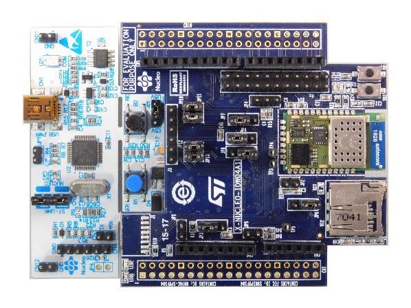
13 Lab 1 : EVAL of the SPWF04 module X-NUCLEO-IDW04A1 & X-CUBE-WIFI1 13 X-NUCLEO-IDW04A1 X-NUCLEO-IDW04A1 is a Wi-Fi evaluation board based on SPWF04 module X-CUBE-WIFI1 X-CUBE-WIFI1 SW package Link to X-CUBE-WIFI1
14 Lab 1.1 : UART Configuration Set Vcom binary in Nucleo X-NUCLEO-IDW04A1 & X-CUBE-WIFI 14 1 Put the Jumpers in the right position
15 Lab 1.1 : UART Configuration Set Vcom binary in Nucleo X-NUCLEO-IDW04A1 & X-CUBE-WIFI Flash UART VCOM binary into Nucleo drive drag and drop Project.bin on Nucleo drive binaries IDE s project NUCLEO-F401RE, F411, L476RG


16 Lab 1.1 : Configuring the UART X-NUCLEO-IDW04A1 & X-CUBE-WIFI Setup TeraTerm window in order to send AT command to Wi-Fi module Open Hyper terminal or TeraTerm Select right COM port Terminal setup Serial port setup 1ms delay not needed anymore starting from X-CUBE-WIFI v3.02
17 Lab 1.1 : Configuring the UART X-NUCLEO-IDW04A1 & X-CUBE-WIFI1 17 Open Tera Term Command Mode Type AT followed by a carriage return (CR) Tera Term output AT AT-S.OK
18 You are ready to use your Wi-Fi EVAL board!
19 Lab 1.2 : For SPI Configuration Set Vcom binary in Nucleo X-NUCLEO-IDW04A1 & X-CUBE-WIFI Put the Jumpers in the right position
20 Lab 1.2 : Running some project in SPI 20 1 Some projects are available using SPI in X-CUBE-WIFI1 2 For example socket client project using STM32F401RE In wifi_conf.h select SPI (comment line as per below) Compile and run available project
21 You are ready to use your Wi-Fi EVAL board!
22 Lab 1.3 : For MicroPython Configuration X-NUCLEO-IDW04A1 & X-CUBE-WIFI Dedicated app note is available on st.com AN4964 : MicroPython scripting language over SPWF04S 2 Below is very basic micro python example from pyb import LED import utime l = LED(2) l.on() cnt=0 while True: l.toggle() cnt=cnt+1 utime.sleep(1) print('loop ', str(cnt)) if cnt == 100: break


23 Lab 1.3 : For MicroPython Configuration X-NUCLEO-IDW04A1 & X-CUBE-WIFI As stated in AN4964, below parameter must be set in order to enable micropython through console AT+S.SCFG=console_enabled,2 AT+S.WCFG AT+S.RESET 4 Here we will simply create & load this script in RAM (see chapter ) AT+S.FSC=blink_led.py,173 5 Confirm file is now created in RAM AT+S.FSL

24 Lab 1.3 : For MicroPython Configuration X-NUCLEO-IDW04A1 & X-CUBE-WIFI Execute micro python script
25 You are ready to use your Wi-Fi EVAL board!

26 Lab 2 : Set the SPWF variables 26 Objective Run a command Get the default configuration dump Set host name Set static IP parameters Reset the module Prerequisites Work alone
![Lab 2 : Run a command 27 Run a command - Syntax - AT+S.[Command]<CR> AT Command Prefix Not case sensitive AT+S.RESET AT+S.SSIDTXT Response Syntax AT+S.WCFG - Optional «AT-S.](/docs-images/71/65814168/images/27-2.jpg "Output» to monitor command execution, followed by - «AT-S.OK» - «AT-S.")
27 Lab 2 : Run a command 27 Run a command - Syntax - AT+S.[Command]<CR> AT Command Prefix Not case sensitive AT+S.RESET AT+S.SSIDTXT Response Syntax AT+S.WCFG - Optional «AT-S.Output» to monitor command execution, followed by - «AT-S.OK» - «AT-S.ERROR:Number:Reason» Both monitoring and error verbosity level and can be set by proper configuration variables

28 Lab 2 : Get the SPWF variables 28 Get the default configuration dump Type AT+S.GCFG Get a variable value Type AT+S.GCFG=console_speed Config dump frame Variable Name Variable Value How to change the variable value? 1. AT+S.SCFG=[var name],xxxx 2. AT+S.WCFG
29 Lab 2 : Set the SPWF variables 29 Get the default configuration dump Set host name When you're going to change the radio settings, we advise to you to turn off the wifi during the whole configuration and to turn on again at the end. Type AT+S.SCFG=ip_hostname,xxxxxxxx Up to 31 characters (case sensitive), spacebar is allowed Tera Term output AT+S.SCFG=ip_hostname,xxxxxxxx AT-S.OK
30 Lab 2 : Set the SPWF variables 30 Get the default configuration dump Set host name Set IP address, IP default gateway, IP DNS and IP netmask (for static usage) Type AT+S.SCFG=ip_ipaddr, Type AT+S.SCFG=ip_gw, Type AT+S.SCFG=ip_dns1, Type AT+S.SCFG=ip_netmask, Tera Term output AT+S.SCFG=ip_ipaddr, AT-S.OK AT+S.SCFG=ip_gw, AT-S.OK AT+S.SCFG=ip_dns1, AT-S.OK AT+S.SCFG=ip_netmask, AT-S.OK
31 Lab 2 : Set the SPWF variables 31 Get the default configuration dump Set host name Set IP address, IP default gateway, IP DNS and IP netmask Save settings on the flash memory Type AT+S.WCFG Reset the module Type AT+S.RESET Tera Term output AT+S.WCFG AT-S.OK AT+S.RESET +WIND:2:Reset
32 Lab 2 : Set the SPWF variables 32 Get the default configuration dump Set host name Set IP address, IP default gateway, IP DNS and IP netmask Save settings on the flash memory (mandatory after a variable change) and reset the module Check the new configuration dump Type AT+S.GCFG
33 Proceed to the next LAB!
34 Lab 3 : Firmware Upgrade 34 Objective Upgrade the Firmware using 4 different methods Prerequisites Getting latest Firmware from ST
35 Lab 3 : Firmware Upgrade 35 FW Upgrade : why? As for any supplier providing chipset with integrated FW, user must ensure possibility to perform FW upgrade. Each new FW version is developed with objective of bringing maturity or new features while keeping backward compatibility with previous FW. FW upgrade is a must to ensure customer homogeneous production.
36 Lab 3.1 : Upgrade through UART 36 Objective Upgrade the FW using UART Prerequisites HEX file (provided in the STSW-WIFI004 FW package)


37 Lab 3.1 : Upgrade through UART 37 A dedicated FW must be set Nucleo board Flash Nucleo with binary available in SW package X-CUBE-WIFI1. Get hex file from latest STWS_WIFI004 package.
38 Lab 3.1 : Upgrade through UART 38 Preparing the X-NUCLEO-IDW04A1 Board Set a jumper on JP2 as shown on picture. This will pull the BOOT0 pin high (force bootmode on Wi-Fi module) Connect X-NUCLEO-IDW04A1 and NUCLEO and connect Nucleo to PC through USB RESET both boards (press SW1 on X-NUCLEO-IDW04A1 and the B2 on the NUCLEO)

39 Lab 3.1 : Upgrade through UART 39 Downloading the Flash Loader tool
40 Lab 3.1 : Upgrade through UART 40 Run flash loader with X-NUCLEO IDW04A1 board Select COM port (If not, use the PC s Device Manager to load the device driver. The USB to UART bridge should be in the list of Ports (COM & LPT) devices.) Set correct settings Baud Rate = Parity = Even Echo Disabled Timout 20 Click the Next button.


41 Lab 3.1 : Upgrade through UART 41 X-NUCLEO-IDW04A1 board is ready for programming. If communication is OK click the Next button. Select FW hex file and click on «next». At the end of FW upgrade, remove JP2 jumper and press RESET button SW1 on X- NUCLEO-IDW04A1 board.
42 Proceed to the next LAB!
43 Lab 3.2 : Upgrade through SWD 43 Objective Upgrade the FW using SWD Prerequisites HEX file (provided in the SPWF04S FW package)
44 Lab 3.2 : Upgrade through SWD 44 X-NUCLEO-IDW04A1 J1 Connector details
45 Lab 3.2 : Upgrade through SWD 45 Download & install ST-Link Utility tool Program SPWF04 through SWD Click on Target button Click on open button Select hex file Program SPWF04
46 Proceed to the next LAB!
47 Lab 3.3 : FOTA update 47 Objective Upgrade the Firmware using the FOTA file Prerequisites FOTA file (provided in the SPWF04S FW package) External web server (i.e. Apache web server running on PC)
48 Lab 3.3 : FOTA update 48 The SPWF04S module allows performing a Firmware Over-the-air update via a single HTTP (or HTTPS) GET. The SPWF04S will validate the firmware image it downloads, load it into a staging area, then prompt the user to issue a reset command in order to complete the update.
 Note: please check that the local firewall is disabled or properly set. It can block the connection from module to Apache. Copy the OTA file (i.e. SPWF04S-xxxxxxx-yyyyyyy- Release.")
49 Lab 3.3 : FOTA update 49 Apache Web Server will be used in this LAB (Apache Web Server is available at this link: Note: please check that the local firewall is disabled or properly set. It can block the connection from module to Apache. Copy the OTA file (i.e. SPWF04S-xxxxxxx-yyyyyyy- Release.fota) in the Apache 2.2 htdocs folder
50 Lab 3.3 : FOTA update 50 The FWUPDATE command allows to perform a Firmware Over-theair update via a single HTTP (or HTTPS) GET. Syntax AT+S.FWUPDATE=e,<hostname>,[<path&queryopts>],[<port>],[<TLS>],[<user name>],[<passwd>]<cr> Configuration parameters <hostname> Target host. DNS resolvable name or IP address. <path&queryopts> Default: /fw.ota. Document path and optional query arguments. If a secure FOTA is required, the extension of the file needs to be.sfota. <port> Default 80 (if TLS=0) or 443 (if TLS>0). <TLS> Default: 0. Values range: 0->unsecured; 1->autodetect; 2-> TLS <username> Default: none. <passwd> Default: none.
51 Lab 3.3 : FOTA update 51 The module and the Apache Web server must be connected to the same network Reset the module to apply the new FW Type AT+S.RESET Restore factory default settings (mandatory) Type AT+S.FCFG Tera Term output In Tera Term: type AT+S.FWUPDATE=e, x.yyy,\SPWF04S-xxxxxxxyyyyyyy-Release.fota,,,, AT+S.FWUPDATE=e, x.yyy,\SPWF04Sxxxxxxx-yyyyyyy-Release.fota,,,, AT-S.Write chunk:2048: AT-S.Write chunk:2048: [ ] AT-S.Write chunk:2048:81f0000 AT-S.Write chunk:740:81f0800: AT-S.OK AT+S.RESET +WIND:2:Reset +WIND:17:Boot:1.0 +WIND:17:Performing F/W update +WIND:17:Completed F/W update +WIND:17:Cleanup AT+S.FCFG AT-S.OK
52 Proceed to the next LAB!

53 Lab 3.4 : SFOTA update 53 Objective Upgrade the Firmware using the SFOTA file Prerequisites SFOTA Creation Folder HEX file Key.bin file External web server (i.e. Apache web server running on PC)
54 Lab 3.4 : SFOTA update 54 The SPWF04S module allows performing a Secure Firmware Overthe-air update via a single HTTP (or HTTPS) GET. The SPWF04S will validate the firmware image it downloads, load it into a staging area, decrypt it, and then prompt the user to issue a reset command in order to complete the update.

55 Lab 3.4 : SFOTA update 55 Drag and drop SPWF04 FW HEX file to the SFOTA Creation Folder Edit the hex2ota.bat file and set name of your HEX file (here SPWF04S-Release.hex) accordingly.


56 Lab 3.4 : SFOTA update 56 Launch the bat file OTA file is created Presentation Title 07/11/2017
 Note: please check that the local firewall is disabled or properly set. It can block the connection from module to Apache. Copy the SFOTA file (i.e. SPWF04S-xxxxxxx-yyyyyyy- Release.")
57 Lab 3.4 : SFOTA update 57 The Apache Web Server will be used (Apache Web Server is available at this link: Note: please check that the local firewall is disabled or properly set. It can block the connection from module to Apache. Copy the SFOTA file (i.e. SPWF04S-xxxxxxx-yyyyyyy- Release.sfota) in the Apache 2.2 htdocs folder


58 Lab 3.4 : SFOTA update 58 Open the key.bin file, in the FOTA Creation Folder, with Notepad ++ for example In the Plugins tab, choose ASCII -> HEX in Converter This is the key you have to enter in the aes128_key variable of the module, look how do that in the next slide
59 Lab 3.4 : SFOTA update 59 Type AT+S.SCFG=aes128_key,xx:yy:xx:yy:xx:yy:xx:yy:xx:yy:xx:yy:xx:yy:xx type AT+S.WCFG Tera Term output AT+S.SCFG=aes128_key,xx:yy:xx:yy:xx:yy:xx:yy:xx:yy:xx:yy:xx:yy:xx AT-S.OK AT+S.WCFG AT-S.OK
60 Lab 3.4 : SFOTA update 60 The FWUPDATE command allows to perform a Secure Firmware Over-the-air update via a single HTTP (or HTTPS) GET. Syntax AT+S.FWUPDATE=e,<hostname>,[<path&queryopts>],[<port>],[<TLS>],[<user name>],[<passwd>]<cr> Configuration parameters <hostname> Target host. DNS resolvable name or IP address. <path&queryopts> Default: /fw.ota. Document path and optional query arguments. If a secure FOTA is required, the extension of the file needs to be.sfota. <port> Default 80 (if TLS=0) or 443 (if TLS>0). <TLS> Default: 0. Values range: 0->unsecured; 1->autodetect; 2-> TLS <username> Default: none. <passwd> Default: none.
61 Lab 3.4 : SFOTA update 61 The module and the Apache Web server must be connected to the same network In Tera Term: type AT+S.FWUPDATE=e, x.yyy,\SPWF04S-xxxxxxx-yyyyyyy- Release.sfota,,,, Reset the module to apply the new FW Type AT+S.RESET Restore factory default settings (mandatory) Type AT+S.FCFG Tera Term output AT+S.FWUPDATE=e, x.yyy,\SPWF04Sxxxxxxx-yyyyyyy-Release.sfota,,,, AT-S.Write chunk:2048: AT-S.Write chunk:2048: [ ] AT-S.Write chunk:2048:81f0000 AT-S.Write chunk:740:81f0800: AT-S.OK AT+S.RESET +WIND:2:Reset +WIND:17:Boot:1.0 +WIND:17:Performing F/W update +WIND:17:Completed F/W update +WIND:17:Cleanup AT+S.FCFG AT-S.OK
62 Proceed to the next LAB!
63 Lab 4 : Used modes 63 Objective Create a direct connection between the module and a device or an Access Point Prerequisites Work alone
64 Lab 4.1 : MiniAP mode 64 Objective Create a direct connection between the module and an end device Prerequisites Work alone
65 Lab 4.1 : Configuring the module in MiniAP mode 65 Type AT+S.WIFI=0 Set the SSID Type AT+S.SSIDTXT=SPWF04_AP WPA2 available in MiniAP from FW1.1 Set the network privacy mode (0=OPEN, 1=WEP, 2=WPA) Type AT+S.SCFG=wifi_priv_mode,0 Set the network mode (1 = STA, 2 = IBSS, 3 = MiniAP) Type AT+S.SCFG=wifi_mode,3 Type AT+S.WIFI=1 Tera Term output AT+S.WIFI=0 AT-S.OK AT+S.SSIDTXT=SPWF04_AP AT-S.OK AT+S.SCFG=wifi_priv_mode,0 AT-S.OK AT+S.SCFG=wifi_mode,3 AT-S.OK AT+S.WIFI=1 AT-S.OK
66 Lab 4.1 : Configuring the module in MiniAP mode 66 SPWF04_AP Tera Term output +WIND:32:WiFi Hardware Started +WIND:26:WiFi Started AP:SPWF04_AP +WIND:24:WiFi Up:
67 Lab 4.1 : Configuring the module in MiniAP mode (WEP Key) 67 Configure the module using the WEP key (2 possible combinations available) Sample table: AP configuration Security Mode: WEP WEP Key Length: 64 bit (10 hex digits) Authentication: Open Wep Key 1: AT command to be used AT+S.WIFI=0 AT+S.SSIDTXT=SPWF04_AP AT+S.SCFG=wifi_wep_keys[0], AT+S.SCFG=wifi_wep_key_lens,05 AT+S.SCFG=wifi_auth_type,0 AT+S.SCFG=wifi_priv_mode,1 AT+S.SCFG=wifi_mode,3 AT+S.WIFI=1 AP configuration Security Mode: WEP WEP Key Length: 128 bit (26 hex digits) Authentication: Open Wep Key 1: AT command to be used AT+S.WIFI=0 AT+S.SSIDTXT=SPWF04_AP AT+S.SCFG=wifi_wep_keys[0], AT+S.SCFG=wifi_wep_key_lens,0D AT+S.SCFG=wifi_auth_type,0 AT+S.SCFG=wifi_priv_mode,1 AT+S.SCFG=wifi_mode,3 AT+S.WIFI=1
68 Lab 4.1 : Configuring the module in MiniAP mode (WEP Key) 68 Notes: wifi_wep_key_lens variable values: 05 and 0D It s possible to enter any text string as WEP key. It have to be converted into a hexadecimal key using the ASCII values of the characters. A maximum of 5 text characters can be entered for 64 bit keys, and a maximum of 13 characters for 128 bit keys. In this case, it needs to manually convert your ASCII password to HEX and complete the wifi_wep_keys[0] variable with the HEX value. i.e. WEP key: test1 ASCII to HEX: 74:65:73:74:31 So, the AT command is: AT+S.SCFG=wifi_wep_keys[0],
69 Lab 4.1 : Customizing the MiniAP address (optional) 69 Type AT+S.WIFI=0 Set the SSID Type AT+S.SSIDTXT=SPWF04_AP Set the network privacy mode (0=OPEN or 1=WEP are supported, WPA2 supported from FW1.1) Type AT+S.SCFG=wifi_priv_mode,0 Set the network mode (1 = STA, 2 = IBSS, 3 = MiniAP) Type AT+S.SCFG=wifi_mode,3 Set the MiniAP address Type AT+S.SCFG=ip_ipaddr, Type AT+S.WIFI=1 Tip: the MiniAP will assign sequential addresses to the client i.e. 1 client: , 2 client: Tera Term output AT+S.WIFI=0 AT-S.OK AT+S.SSIDTXT=SPWF04_AP AT-S.OK AT+S.SCFG=wifi_priv_mode,0 AT-S.OK AT+S.SCFG=wifi_mode,3 AT-S.OK AT+S.SCFG=ip_ipaddr, AT-S.OK AT+S.WIFI=1 AT-S.OK +WIND:32:WiFi Hardware Started +WIND:26:WiFi Started AP with network 'SPWF04_AP' +WIND:24:WiFi Up:
70 Lab 4.1 : Mini AP mode 70 Associate your end device to the SPWF04_AP network Find the SPWF_AP network and connect the end device to the module SPWF04_AP Tera Term output +WIND:28:Station Associated:90:18:7C:96:0D:0B:0 +WIND:29:DHCP reply:
71 Proceed to the next LAB!
72 Lab 4.2 : Station mode 72 Objective Connect the SPWF04 Module to an Access Point Prerequisites USB dongle and computer are set up as described in Lab 2 Work alone
73 Lab : Access point connection through UART 73 Objective Scan for available networks Join a network Check the status/statistics variables Prerequisites Work alone
74 Lab : Scan for available networks 74 The SCAN command performs an immediate scan for available networks. Infrastructure (AP) and IBSS (Ad-Hoc) networks are both reported. Network type, Channel, BSSID, SSID, Signal strength (RSSI), and capabilities are all reported. Type AT+S.SCAN=d,ScanResult Type AT+S.FSP=ScanResult,, Do a scan without any filter. Put the scans result in the file named ScanResult, if no ScanResult file is given, output will be show on console Show the contains of the file ScanResult Tera Term output AT+S.SCAN=d,ScanResult AT-S.Parsing Networks:3 AT-S.OK AT+S.FSP=ScanResult,, 1: BSS 14:D6:4D:24:36:00 CHAN: 01 RSSI: -28 SSID: 'ENG-WPA' CAPS: 0431 WPA WPA2 2: BSS 00:18:0A:31:EA:78 CHAN: 11 RSSI: -82 SSID: 'ZyckoItalyWireless' CAPS: 0531 WPA WPA2 3: BSS 06:18:0A:31:E7:E2 CHAN: 11 RSSI: -85 SSID: 'ZyckoItalyGuest' CAPS: 0531 WPA WPA2 Network type Network MAC Network channel Network RSSI Network SSID Network capabilities
75 Lab : Joining a network (WPA Key) 75 If the device isn t WPS compliant, the AP parameters setting is needed. Type AT+S.WIFI=0 Set the SSID Type AT+S.SSIDTXT=ENG_WPA Set the password Type AT+S.SCFG=wifi_wpa_psk_text,helloworld Set the network privacy mode (0=none, 1=WEP, 2=WPA-Personal (TKIP/AES) or WPA2-Personal (TKIP/AES)) Type AT+S.SCFG=wifi_priv_mode,2 N.B. wifi_auth_type must be set to 0 AT+S.SCFG=wifi_auth_type,0 Set the network mode (1 = STA, 2 = IBSS, 3 = MiniAP) Type AT+S.SCFG=wifi_mode,1 Type AT+S.WIFI=1 Tera Term output All AT-S.OK
76 Lab : Joining a network (WPA Key) 76 ENG-WPA AP Tera Term output +WIND:46:WPA Crunching PSK:mypassword:10 +WIND:32:WiFi Hardware Started +WIND:21:WiFi Scanning +WIND:35:WiFi Scan Complete (0x0) +WIND:19:WiFi Join:14:D6:4D:24:36:00 +WIND:25:WiFi Association with 'ENG- WPA' successful +WIND:51:WPA Handshake Complete +WIND:24:WiFi Up: xx
77 Lab : Joining a network (WPA Key) 77 Check the status/statistics variables Type AT+S.STS Send a ping to the gateway (ip_gw) Type AT+S.PING=,, ENG-WPA AP Tera Term output AT+S.PING=,, AT-S.OK
78 Lab : Joining a network (WEP Key) 78 Configure the module using the WEP key (4 possible combinations available) Sample table: AP configuration Security Mode: WEP WEP Key Length: 64 bit (10 hex digits) Authentication: Open Wep Key 1: Security Mode: WEP WEP Key Length: 64 bit (10 hex digits) Authentication: Shared Key Wep Key 1: AT command to be used AT+S.WIFI=0 AT+S.SSIDTXT=ENG-WEP AT+S.SCFG=wifi_wep_keys[0], AT+S.SCFG=wifi_wep_key_lens,05 AT+S.SCFG=wifi_auth_type,0 AT+S.SCFG=wifi_priv_mode,1 AT+S.SCFG=wifi_mode,1 AT+S.WIFI=1 AT+S.WIFI=0 AT+S.SSIDTXT=ENG-WEP AT+S.SCFG=wifi_wep_keys[0], AT+S.SCFG=wifi_wep_key_lens,05 AT+S.SCFG=wifi_auth_type,1 AT+S.SCFG=wifi_priv_mode,1 AT+S.SCFG=wifi_mode,1 AT+S.WIFI=1 AP configuration Security Mode: WEP WEP Key Length: 128 bit (26 hex digits) Authentication: Open Wep Key 1: Security Mode: WEP WEP Key Length: 128 bit (26 hex digits) Authentication: Shared Key Wep Key 1: AT command to be used AT+S.WIFI=0 AT+S.SSIDTXT=ENG-WEP AT+S.SCFG=wifi_wep_keys[0], AT+S.SCFG=wifi_wep_key_lens,0D AT+S.SCFG=wifi_auth_type,0 AT+S.SCFG=wifi_priv_mode,1 AT+S.SCFG=wifi_mode,1 AT+S.WIFI=1 AT+S.WIFI=0 AT+S.SSIDTXT=ENG-WEP AT+S.SCFG=wifi_wep_keys[0], AT+S.SCFG=wifi_wep_key_lens,0D AT+S.SCFG=wifi_auth_type,1 AT+S.SCFG=wifi_priv_mode,1 AT+S.SCFG=wifi_mode,1 AT+S.WIFI=1
 79 Notes: wifi_wep_key_lens variable values: 05 and 0D It s possible to enter any text string into a WEP key box in the AP, in which case it will be converted into a")
79 Lab : Joining a network (WEP Key) 79 Notes: wifi_wep_key_lens variable values: 05 and 0D It s possible to enter any text string into a WEP key box in the AP, in which case it will be converted into a hexadecimal key using the ASCII values of the characters. A maximum of 5 text characters can be entered for 64 bit keys, and a maximum of 13 characters for 128 bit keys. In this case, it needs to manually convert your ASCII password to HEX and complete the wifi_wep_keys[0] variable with the HEX value. i.e. AP WEP key: test1 ASCII to HEX: 74:65:73:74:31 So, the AT command is: AT+S.SCFG=wifi_wep_keys[0], Some APs allow user to insert a passphrase and then the AP automatically generates the hex keys. In this scenario, user have not to perform the ASCII to HEX conversion because the AP already gives it the hex value.
80 Proceed to the next LAB!
81 Lab : Access point connection through WPS 81 Objective Create a direct connection between the module and a generic AP with WPS option Prerequisites Work alone
82 Lab : Joining a network through WPS 82 In order to be connected to an available Wifi network, the AP parameters setting was needed, but now, with the WPS, it isn t longer the case. There are 2 options Hardware : Press the WPS button of the AP and the SW2 of the SPWF04 Software : Press the WPS button of the AP and Type AT+S.WPS=0 in Tera Term Tera Term output AT+S.WPS=0 AT-S.OK +WIND:46:WPA Crunching PSK:mypassword:10 +WIND:25:WiFi Association successful:ap
83 Proceed to the next LAB!
84 Lab : MiniAP mode for the first set 84 Objective Create a direct connection between the module and an end device First set of the module in order to enable the connection between the module and a generic AP Prerequisites Work alone
85 Lab : Configuring the module in MiniAP mode 85 Type AT+S.WIFI=0 Set the SSID Type AT+S.SSIDTXT=SPWF04_AP Set the network privacy mode (0=OPEN or 1=WEP are supported) Type AT+S.SCFG=wifi_priv_mode,0 Set the network mode (1 = STA, 2 = IBSS, 3 = MiniAP) Type AT+S.SCFG=wifi_mode,3 Type AT+S.WIFI=1 Tera Term output AT+S.WIFI=0 AT-S.OK AT+S.SSIDTXT=SPWF04_AP AT-S.OK AT+S.SCFG=wifi_priv_mode,0 AT-S.OK AT+S.SCFG=wifi_mode,3 AT-S.OK AT+S.WIFI=1 AT-S.OK
86 Lab : Configuring the module in MiniAP mode 86 SPW04_AP Tera Term output +WIND:32:WiFi Hardware Started +WIND:26:WiFi Started AP:SPWF04_AP +WIND:24:WiFi Up:
87 Lab : Mini AP mode 87 Associate your end device to the SPWF04_AP network Find the SPWF04_AP network and connect the end device to the module SPWF04_AP Tera Term output +WIND:28:Station Associated:90:18:7C:96:0D:0B:0 +WIND:29:DHCP reply:
88 Lab : Mini AP mode 88 Open your web browser In the address bar, type the value of the variable ip_ipaddr or capitveportal.net Tip: If the AP domain name is not quickly opened, it s suggested to turn off an eventual proxy server (check the connection settings or browser preferences) SPWF04_AP Tip: The Mini AP domain can be set using the variable ip_apdomainname. The default value is captiveportal.net. The Mini AP default homepage can be set using the variable ip_apredirect. The default value is firstset.html.
89 Lab : First Set Page 89 The first set page allows to configure the module in IDLE mode, STATION mode, IBSS mode and MINI AP mode. Mandatory for IDLE, STA, IBSS, MINI AP Used for STA, IBSS, MINI AP Used for STA, IBSS (WEP), MINI AP (WEP) Used for STA (if DHCP = OFF), IBSS (mandatory), MINI AP (if DHCP = OFF) Used for STA, IBSS (mandatory DHCP = OFF), MINI AP Used for STA (WEP key), IBSS (WEP), MINI AP (WEP) Used for STA, IBSS, MINI AP
90 Lab : Mini AP mode 90 Set all the parameters required in order to enable the connection between the module and a generic AP i.e. AP configured in WPA/WPA2 mode MiniAP PassKey: anonymous (by default) SSID of the access point Password of the access point Authentication type of the access point Use mode of the module Tip: The Mini AP PassKey can be set using the variable user_desc. The default value is anonymous.

91 Lab : Mini AP mode 91 Click on the Push button and then send the parameters confirming with OK AP SSID: ciscosb2 SPWF04_AP
92 Lab : Mini AP mode 92 The module will receive the parameters and will automatically connect to the access point required Tera Term output AP ciscosb2 +WIND:57:Received SSID is ciscosb2 +WIND:57:Received PWD is ********** +WIND:57:Received Auth mode is 2 +WIND:57:Received Mode is 1 +WIND:2:Reset +WIND:1:Poweron:xxxxxxx-yyyyyyy-SPWF04S +WIND:13:Copyright (c) STMicroelectronics, Inc. All rights Reserved:SPWF04Sx +WIND:3:Watchdog Running +WIND:0:Console active +WIND:46:WPA Crunching PSK:mypassword:10 +WIND:32:WiFi Hardware Started +WIND:21:WiFi Scanning +WIND:35:WiFi Scan Complete (0x0) +WIND:19:WiFi Join:02:62:1F:51:8F:0B +WIND:25:WiFi Association with 'ciscosb2' successful +WIND:51:WPA Handshake Complete +WIND:24:WiFi Up:
93 Proceed to the next LAB!
94 Lab 4.3 : STA/MINI AP switcher 94 Objective Hardware Station to Mini AccessPoint switcher Prerequisites Work alone
95 Lab 4.3 : STA/MINI AP switcher 95 This feature allows to force the module in Mini AP mode starting from a preexistent state. Recovery Mode : this functionality could be useful to lead the module in a known state and to reconfigure it (i.e. using the firstset page). The GPIO7 will be used to drive this feature.

96 Lab 4.3 : STA/MINI AP switcher 96 Press and hold the SW1 button on the EVAL to perform a reset and click the SW2 button Release the SW1 button The MiniAP mode will be started and the module is discoverable with the following SSID: iwm-xx-yy-zz where XX-YY-ZZ are the last six digits of module s MAC ADDRESS Tera Term output +WIND:1:Poweron:xxxxxxx-yyyyyyy- SPWF04S +WIND:13:Copyright (c) STMicroelectronics, Inc. All rights Reserved:SPWF04Sx +WIND:39:HW in miniap mode +WIND:0:Console active +WIND:3:Watchdog Running +WIND:32:WiFi Hardware Started +WIND:26: Started AP: iwm-xx-yy-zz +WIND:24:WiFi Up:
97 Proceed to the next LAB!

98 Lab 4.4 : IBSS connection 98 Objective Create an IBSS network Prerequisites Work alone
99 Lab 4.4 : Create an IBSS network 99 In an IBSS network, the SSID is chosen by the client device that starts the network. Module settings to create an IBSS network: Type AT+S.WIFI=0 Set the IBSS SSID0 Type AT+S.SSIDTXT=ADHOC Set the network privacy mode (0=OPEN or 1=WEP are supported) Type AT+S.SCFG=wifi_priv_mode,0 Set the network mode (2 = IBSS) Type AT+S.SCFG=wifi_mode,2 Tera Term output AT+S.WIFI=0 AT-S.OK AT+S.SSIDTXT=ADHOC AT-S.OK AT+S.SCFG=wifi_priv_mode,0 AT-S.OK AT+S.SCFG=wifi_mode,2 AT-S.OK
100 Lab 4.4 : Create an IBSS network 100 Set IP address, IP default gateway, IP DNS and IP netmask Type AT+S.SCFG=ip_ipaddr, y.1xx Type AT+S.SCFG=ip_gw, y.1 Type AT+S.SCFG=ip_dns1, y.1 Type AT+S.SCFG=ip_netmask, Turn off the DHCP Type AT+S.SCFG=ip_use_dhcpc,0 Tera Term output AT+S.SCFG=ip_ipaddr, AT-S.OK AT+S.SCFG=ip_gw, AT-S.OK AT+S.SCFG=ip_dns1, AT-S.OK AT+S.SCFG=ip_netmask, AT-S.OK AT+S.SCFG=ip_use_dhcp,0 AT-S.OK
101 Lab 4.4 : Create an IBSS network 101 Save the settings on the flash memory and reset the module Type AT+S.WIFI=1 AD-HOC Tera Term output


102 Lab 4.4 : Create an IBSS network 102 Associate the device with the ADHOC network (ios > 8 could not support the IBSS mode) Tip: manual configuration of static TCP/IPv4 parameters is suggested using a PC I.e. PC TCP/IPv4 properties AD-HOC

103 Lab 4.4 : Create an IBSS network 103 Find your IP address Type AT+S.STS Open Safari web browser In the address bar, type <SPWF IP address>/index.html Type /index.html AD-HOC
104 Proceed to the next LAB!
105 Lab 5 : mdns 105 Objective Successfully see the module and see its capabilities via the mdns protocol Prerequisites Work alone

106 Lab 5 : mdns 106 Press and hold the SW1 button on the EVAL to perform a reset and click the SW2 button Release the SW1 button. You are, now, in MiniAP mode. Download and open ZeroConf Browser app on your smartphone, activate wifi and notice this : Thanks to mdns support you are able to discover service capabilities
107 Proceed to the next LAB!
108 Lab 6 : Socket interface 108 Objective Open TCP/UDP connection Write data to socket Read data from socket Query socket List socket Close socket Broadcast Socket Server Prerequisites Work alone Socket Client TCP/UDP socket
109 Lab 6 : TCP/UDP/Secure socket interface 109 The Socket interface allows communication via TCP, UDP or secure connection. The SPWF04 can be both a client and a server socket. The SPWF can be in whatever mode (MiniAP or Station Mode). For secure socket, please refer to Security_on_SPWF04S Application Notes. Open TCP/UDP connection End Product Host Write data to socket Read data from socket Close socket
110 Lab 6.1 : Socket Client 110 Objective Open a TCP or UDP connection from the module to a socket server Prerequisites module connected to the AP (Lab 4.2) or module configured in MiniAP (Lab 4.1) mode PC to be used as socket server Socket Client Socket Server TCP socket
111 Lab 6.1 : Socket Client 111 The Socket interface allows communication via TCP, UDP or secure connection. The SPWF is both a client and a server socket. In this LAB, will detail the socket client feature. Open TCP/UDP connection End Product Host Write data to socket Read data from socket Close socket
112 Lab 6.1 : Open Socket Client connection 112 The SOCKON command allows to open a TCP/UDP connection to a specified host (up to 8 socket connections at same time). Syntax AT+S.SOCKON=<hostname>,<port>,,<kind><cr> Configuration parameters <hostname> Remote Server. DNS resolvable name or IP address. <port> TCP/UDP socket port <kind> This parameter can assume the values: t->tcp u->udp s->tls socket using <Hostname> as domain name TLS Server Domain Name: Common Name of the server (URL or the CN field reported into server certificate) for TLS socket

113 Lab 6.1 : Open Socket Client connection 113 Open the TCP socket server (disable the firewall to properly run it) Folder../hands_on_wifi/tcp socket server/server.exe The TCP server listens for incoming connections on the port It sends back all data received.
114 Lab 6.1 : Open Socket Client connection 114 Using an Android platform, the socket server can be opened using a specific APP (Socket Protocol, available on Play Store) The TCP socket server can be configured to listen for incoming connections on the port Type on «Port Listen to» box Click on Listen
115 Lab 6.1 : Open Socket Client connection 115 Type AT+S.SOCKON=<hostname>,32000,,t Hostname could be DNS resolvable name or IP The client and the server use the socket identifier (ID) displayed Tera Term output AT+S.SOCKON=<hostname>,32000,,t AT-S.On:hostIPadress:0 AT-S.OK
116 Lab 6.1 : To query a socket client for length of pending data 116 The SOCKQ command allows to read data from socket. Syntax AT+S.SOCKQ=<ID> Configuration parameters <ID>: socket identifier Tera Term output AT+S.SOCKQ=<ID> AT-S.Query:Lengthofdata AT-S.OK
117 Lab 6.1 : Write data to socket 117 The SOCKW command allows to write data to the specified ID socket. This command accepts data after the <cr> at the end of the command line. Syntax AT+S.SOCKW=<ID>,<len> Configuration parameters <ID>: socket identifier <len>: data length to send
 are sent from the terminal, the module is going to write them to the socket and will be ready to receive new commands.")
118 Lab 6.1 : Write data to socket 118 Write data Type AT+S.SOCKW=0,11 Note: the module is waiting 13 bytes to be written to the socket. As soon as 13 bytes (or characters) are sent from the terminal, the module is going to write them to the socket and will be ready to receive new commands. Type hello world<cr> SPWF shows that there are <pending data> and their amount Tera Term output ID Pending bytes AT+S.SOCKW=0,11 +WIND:55:Pending Data:0:11
119 Lab 6.1 : Read data from socket 119 The SOCKR command allows to read data from socket. Syntax AT+S.SOCKR=<ID>,<len> Configuration parameters <ID>: socket identifier <len>: Defaut:0. Length (in bytes) of the buffer to read. The value 0 indicates to read the full buffer
120 Lab 6.1 : Read data from socket 120 Read data Type AT+S.SOCKR=0, Tera Term output AT+S.SOCKR=0, hello world AT-S.OK
121 Lab 6.1 : Close socket 121 The SOCKC command allows to close socket. Syntax AT+S.SOCKC=<ID> Configuration parameters <ID>: socket identifier
122 Lab 6.1 : Close socket 122 Close socket Type AT+S.SOCKC=0 Tera Term output AT+S.SOCKC=0 AT-S.OK
123 Proceed to the next LAB!
124 Lab 6.2 : Socket Server functionality 124 Objective Configure a Server Listening Port Open a TCP or UDP connection from a socket client to the module Prerequisites module connected to the AP (Lab 4.2) or module configured in MiniAP (Lab 4.1) mode PC to be used as socket client Socket Client Socket Server TCP socket
125 Lab 6.2 : Socket Server 125 This feature allows to enable the socket server mode. The module can be able to listen for an incoming connection on the specified port. The module should be connected to the AP or should be configured in Mini AP mode. We will detailed the socket server in station mode. miniap ENG-WPA AP SPWF04_AP
126 Lab 6.2 : Socket Server 126 Socket server: turn ON the TCP Socket Server (user must specify the server listening port) Type AT+S.SOCKDON=32000,t (AT+SOCKDON=32000,u for UDP socket server or AT+SOCKDON=32000,s1 for one-way and AT+SOCKDON=32000,s2 for mutual secure socket server ) AP ENG-WPA Tera Term output AT+S.SOCKDON=32000,t AT-S.On:0 AT-S.OK
127 Lab 6.2 : Socket Server 127 Socket client: can be used a simple socket client in order to test the communication (Socket Protocol App available on Play Store) AP ENG-WPA
128 Lab 6.2 : Socket Server 128 Socket client: Insert the module s IP Address and the port Click on the Connect button Tera Term output +WIND:61:Incoming Socket Client: XX:12345:0:0

129 Lab 6.2 : Socket Server 129 Try to send and receive data from the module Tera Term output +WIND:55:Pending Data:0:0:4:4
130 Lab 6.2 : List bound socket client 130 The SOCKDL command allows to list bound socket client. Syntax AT+S.SOCKDL AT+S.SOCKDL=<sid><cr> to list bound clients on the specified server Configuration parameters <sid> socket server identifier
131 Lab 6.2 : Write data to a socket client 131 The SOCKDW command allows to read data from socket client. Syntax AT+S.SOCKDW=<sid>,<cid>,<len><cr><data> Configuration parameters <sid> socket server identifier <cid> socket client identifier <len>: Length (in bytes) of the buffer to write that is sent after the command.
132 Lab 6.2 : Read data from socket 132 The SOCKDR command allows to read data from socket client. Syntax AT+S.SOCKDR=<sid>,<cid>,<len><cr> Configuration parameters <sid> socket server identifier <cid> socket client identifier <len>: Defaut:0. Length (in bytes) of the buffer to read. The value 0 indicates to read the entire buffer
133 Lab 6.2 : Read data from socket 133 Read data Type AT+S.SOCKDR=0,0, Tera Term output AT+S.SOCKDR=0,0, AT-S.Reading:5:5 Test AT-S.OK
134 Lab 6.2 : Close socket 134 Syntax AT+S.SOCKDC=<sid> AT+S.SOCKDC=<sid>,<cid> Disconnect all clients, and turn off the server Disconnect specific client, and keep the port open Configuration parameters <sid> socket server identifier <cid> socket client identifier
135 Lab 6.2 : Close socket 135 Close socket Type AT+S.SOCKDC=0 Tera Term output AT+S.SOCKDC=0 AT-S.OK
136 Proceed to the next LAB!
137 Lab 6.3 : Broadcast examples 137 Objective Broadcast with socket server configuration Broadcast between socket client only Prerequisites module connected to the AP (Lab 4.2) or module configured in MiniAP (Lab 4.1) mode PC to be used as socket client Socket Client Socket Server TCP socket
138 Lab 6.3 : First Case, one client to 2 servers 138 Open socket client Type AT+S.SOCKON= ,32000,,u If other modules are also used as socket server, open socket servers (up to 8 socket client connection are supported) Type AT+S.SOCKDON=32000,u Write data on your socket client Type AT+S.SOCKW=0,5<CR>hello Tera Term output of socket client AT+S.SOCKON= ,32000,,u AT-S.On: :0 AT-S.OK AT+S.SOCKW=0,5 AT-S.OK Client Tera Term output of sockets server Server 1 Server 2 AT+S.SOCKDON=32000,u AT-S.On:0 AT-S.OK +WIND:80:UDP Broadcast Received: :5 hello
139 Lab 6.3 : Second Case, sockets client only 139 Open a socket client (the «Broadcaster») Type AT+S.SOCKON= ,32000,,u Open other sockets client (the receivers) Type AT+S.SOCKON= ***,32000,,u (*** corresponding to your Broadcaster) Write data on the «Broadcaster» Type AT+S.SOCKW=0,5<CR>hello Client (Broadcaster) Tera Term output of Broadcaster AT+S.SOCKON= ,32000,,u AT-S.On: :0 AT-S.OK AT+S.SOCKW=0,5 AT-S.OK Tera Term output of sockets server Client 1 Client 2 AT+S.SOCKON= ***,32000,,u AT-S.On:0 AT-S.OK +WIND:55:Pending Data::0:5:5 hello
140 Lab 6.3 : Broadcast as socket server 140 UDP broadcast as socket server not available at the moment, coming soon.
141 Proceed to the next LAB!
142 Lab 7 : Websocket 142 Objective Create a direct connection between the module and an end device Write data to socket Read data from socket Query socket List socket Close socket Prerequisites Work alone Your module have to be connected to an Access point with an Internet Connection
143 Lab 7 : Websocket 143 To begin, you need to use a Websocket Server, for example you can use this one : Click on Connect Presentation Title 07/11/2017
144 Lab 7 : Open TCP/UDP connection 144 The WSOCKON command allows to open a TCP/UDP connection to a specified host. Syntax AT+S.WSOCKON=<hostname>,[<port>],[<path>],[<TLS>],[<username>],[<passwd>],[<origin >],[<protocols>],[<extensions>]<cr> Configuration parameters <hostname> DNS resolvable name or IP address of the Websocket server. <port> Default 80 (if TLS=0) or 443 (if TLS>0). <path> Default:/ <TLS> Default: 0. Values range: 0->unsecured; 1->autodetect; 2-> TLS <username> Default: none. Username on the remote server <passwd> Default: none. Passwd on the remote server <origin> Default:none. Header Field Origin <protocols> Default:none. Header Field Protocols <extensions> Default:none. Header Field Extensions
145 Lab 7 : Websocket 145 So, with the previous example you can type : AT+S.WSOCKON=echo.Websocket.org,80,,,,,,,<CR> Tera Term output AT+S.WSOCKON=echo.Websocket.org,80,,,,,,, AT-S.On:0 AT-S.OK Presentation Title 07/11/2017
146 Lab 7 : Websocket 146 Now you can send a message, in the example, the server returns the message sent : Click the «Send» button Presentation Title 07/11/2017
147 Lab 7 : Write data to Websocket 147 Now, let s do that with the SPWF04 module The WSOCKW command allows to write data to the specified ID socket. This command accepts data after the <cr> at the end of the command line. Syntax AT+S.WSOCKW=<id>,[<lastFrame>],[<lastFrag>],[<binary>],<len><cr> {data} Configuration parameters <id> Websocket client identifier <lastframe> Default:0. 1-> Last frame flag. <lastfrag> Default:0. 1-> Last frag flag. <binary> Default:0, textual. 1-> Binary Flag

148 Lab 7 : Write data to Websocket 148 Write data Type AT+S.WSOCKW=0,1,1,0,6<CR>hello SPWF shows that there are <pending data> and their amount Tera Term output ID Pending bytes AT+S.WSOCKW=0,1,1,0,6 AT-S.OK +WIND:88:Websocket Data:0:0:1:6:6
149 Lab 7 : To query a Websocket client for length of pending data 149 The WSOCKQ command allows to read data from socket. Syntax AT+S.WSOCKQ=<ID><CR> Configuration parameters <ID>: socket identifier Tera Term output AT+S.WSOCKQ=<ID> AT-S.Query:Lengthofdata AT-S.OK
150 Lab 7 : List Websocket 150 The WSOCKL command allows to list opened Websocket clients. Syntax AT+S.WSOCKL<cr> Tera Term output ID Pending bytes Port AT+S.WSOCKL AT-S.List:0:1:6:80 AT-S.OK
151 Lab 7 : Read data from Websocket 151 The WSOCKR command allows to read data from socket. Syntax AT+S.WSOCKR=<ID>,[<len>]<cr> Configuration parameters <ID>: socket identifier <len>: Defaut:0. Length (in bytes) of the buffer to read. The value 0 indicates to read the full buffer
152 Lab 7 : Read data from Websocket 152 Read data Type AT+S.WSOCKR=0, Tera Term output AT+S.WSOCKR=0, AT-S.Reading:5:5 helloat-s.ok
153 Lab 7 : Close Websocket 153 The WSOCKC command allows to close Websocket. Syntax AT+S.WSOCKC=<id>,[<status>]<cr> Configuration parameters <id> Websocket client identifier <status> Default:0; 0--> Normal Closure; 1-> Going Away; For a complete list of the status values defined for the Websocket refer to the related standard.
154 Lab 7 : Close Websocket 154 Close Websocket Type AT+S.WSOCKC=0, Tera Term output AT+S.WSOCKC=0, AT-S.OK
155 Proceed to the next LAB!
156 Lab 8 : HTTP Web Interface 156 Objective Discover module capabilities acting as web client or web server Prerequisites USB dongle and computer are set up as described in Lab 2 Work in couple
157 Lab 8.1 : Web client mode 157 Objective HTTP GET HTTP POST Prerequisites USB dongle and computer are set up as described in Lab 2 Work in couple

158 Lab 8.1 : HTTP POST 158 To perform a post of the specified file to a remote host. Syntax AT+S.HTTPPOST=<hostname>,[<Path&queryopts]>,[<port>],[<TLS Kind>],[<username>],[<passwd>],[<In Filename>],[<Out Filename>]<cr> Configuration parameters <Hostname> DNS resolvable Name or IP address <Path&queryopts> Default:/index.html. document path & optional query arguments. <port> Default 80 (if TLS=0) or 443 (if TLS>0). <TLS> Default: 0. Values range: 0->unsecured; 1->autodetect; 2-> TLS
159 Lab 8.1 : HTTP POST 159 Configuration parameters <username> Default: none. <passwd> Default: none. <In Filename> Default: none. Console. When specified the return data are saved in a file. <Out Filename> Default: none. Filename to transfer to the server.

160 Lab 8.1 : HTTP POST 160 The SPWF04S performs an HTTP POST to an HTTP Post Test Server Type: AT+S.HTTPPOST=posttestserver.com,/post.php,,,,,, The HTTP Post Test Server replies as displayed in the Tera Term output if the HTTP POST successfully Tera Term output A B HTTP POST SERVER AT+S.HTTPPOST=posttestserver.com,/post.php,,,,,, Successfully dumped X post variables. View it at Post body was X chars long. AT-S.OK
161 Lab 8.1 : HTTP GET 161 The Apache Web Server will be used in this tutorial (Apache Web Server is available at this link: Note: please check that the local firewall is disabled or properly set. It can block the connection from module to Apache. Copy the file that you want to get with the http command in the Apache 2.2 htdocs folder (this is the default root server directory) File.txt

162 Lab 8.1 : HTTP GET 162 The HTTP GET feature performs a single HTTP request to the specified host and path. The server response is printed on the UART enabled. Syntax AT+S.HTTPGET=<hostname>,[<Path&queryopts]>,[<port>],[<TLSKind>],[<username>],[<passwd>],[<In Filename>], [<Out Filename>]<cr> Configuration parameters <Hostname> DNS resolvable Name or IP address <Path&queryopts> Default:/index.html. document path & optional query arguments. <port> Default 80 (if TLS=0) or 443 (if TLS>0).
163 Lab 8.1 : HTTP GET 163 Configuration parameters <TLS> Default: 0. Values range: 0->unsecured; 1->autodetect; 2-> TLS <username> Default: none. <passwd> Default: none. <In Filename> Default: none. Custom http requests <Out Filename> Default: Console. When specified the return data are saved in a file.
164 Lab 8.1 : HTTP GET 164 Device A performs an HTTP GET to the Device B Device A: AT+S.HTTPGET=<Device B IP addr>,/file.txt,,,,, Type AT+S.HTTPGET= ,/File.txt,,,,,, A B Tera Term output AT+S.HTTPGET= ,/File.txt,,,,,, ContentofyourfileAT-S.OK
165 Proceed to the next LAB!
166 Lab 8.2 : Web Server mode 166 Web Server Feature Web Server Usage
167 Lab : Web Server Feature 167 Objective List, Print existing files Create a file, Delete an existing file in RAM Create a file in Flash Create Dynamic Pages Prerequisites Work alone
168 Lab : List, Print existing files 168 Objective See the list of files on the server See the contain of a file Prerequisites Work in couple
169 Lab : List existing files 169 The FSL command lists type, sizes and name of all the existing files. Type AT+S.FSL Tera Term output Files stored in the APP Disk AT+S.FSL AT-S.Free RAM Disk:14848 AT-S.File:D 484 ScanResult AT-S.File:I 4241 config.fhtml AT-S.File:I 676 favicon.gz.ico AT-S.File:I 697 firstset.gz.html AT-S.File:I 401 index.gz.html AT-S.File:I 252 input_demo.fhtml AT-S.File:I 658 MULTI_CLIENT_SERVER.py AT-S.File:I 290 output_demo.gz.html AT-S.File:I 1719 peers.fhtml AT-S.File:I 882 remote.gz.html AT-S.File:I 2318 RL_TCP_CL.py AT-S.File:I 2340 RL_TCP_SE.py AT-S.File:I 2696 RL_TCP_SE_GC_COLLECT.py AT-S.File:I 2317 RL_UDP_CL.py AT-S.File:I 2331 RL_UDP_SE.py AT-S.File:I 1768 status.fhtml AT-S.File:I 4134 stlogo.gz.jpg AT-S.File:I 897 WLAN.py AT-S.File:I 1246 WLAN.STA.py AT-S.OK
170 Lab : Print a file 170 The FSP command prints the content of an existing file. Type AT+S.FSP=/input_demo.fhtml,, AT+S.FSP=/input_demo.fhtml,, <!DOCTYPE html PUBLIC "-//W3C//DTD HTML 4.01//EN" " <html> <head><title>input Demo</title></head> <body><fieldset> Tera Term output Tip: How to use the offset and length parameters: AT+S.FSP=/index.html,[offset],[length] <legend><h4>spwf04s Input from Host</h4></legend> <!-- 06 Input 0 --> i.e. AT+S.FSP=/input_demo.fhtml,5,20 Type </fieldset> </body> </html> AT-S.OK
171 Proceed to the next LAB!
172 Lab : Create a file and Delete an existing file in RAM 172 Objective Create a file in RAM Delete a file in RAM Prerequisites Work in couple
173 Lab : Create a file in RAM 173 The FSC command allows to create a file inside the SPWF04 for delivery by the SPWF04 HTTP server, or appends the data following the command in case the file already exists. Syntax AT+S.FSC=<filename>,<datalen><cr>{data} Configuration parameters <filename> name of the file. Max size is 64 bytes <datalen> amount of space in bytes to allocate for the file. Type AT+S.FSC=/wifidemo.html,1965 Tera Term output AT+S.FSC=/wifidemo.html,1965 AT-S.OK
174 Lab : Create a file in RAM 174 Let's list the files Type AT+S.FSL Tera Term output File stored in the RAM Disk AT+S.FSL AT-S.Free RAM Disk:14848 AT-S.File:D 484 ScanResult AT-S.File:I 4241 config.fhtml AT-S.File:I 676 favicon.gz.ico AT-S.File:I 697 firstset.gz.html AT-S.File:I 401 index.gz.html AT-S.File:I 252 input_demo.fhtml AT-S.File:I 658 MULTI_CLIENT_SERVER.py AT-S.File:I 290 output_demo.gz.html AT-S.File:I 1719 peers.fhtml AT-S.File:I 882 remote.gz.html AT-S.File:I 2318 RL_TCP_CL.py AT-S.File:I 2340 RL_TCP_SE.py AT-S.File:I 2696 RL_TCP_SE_GC_COLLECT.py AT-S.File:I 2317 RL_UDP_CL.py AT-S.File:I 2331 RL_UDP_SE.py AT-S.File:I 1768 status.fhtml AT-S.File:I 4134 stlogo.gz.jpg AT-S.File:I 897 WLAN.py AT-S.File:I 1246 WLAN.STA.py AT-S.OK
 In address bar, type")
175 Lab Open wifidemo.html Open your Web browser (suggested Google Chrome for HTML5 test) In address bar, type <SPWF IP addr>/wifidemo.html Type xx/wifidemo.html
176 Lab : Delete an existing file 176 The FSD command allows to delete an existing file by name. Static files may not be deleted. Syntax AT+S.FSD=/<filename> Type AT+S.FSD=/wifidemo.html Tera Term output AT+S.FSD=/wifidemo.html AT-S.OK
177 Proceed to the next LAB!
178 Lab : Create a file in Flash 178 Objective Create a file in Flash FS OTA FS over UART FS over SWD Prerequisites Work in couple
179 Lab : Create an image file 179 Objective Create an image file Prerequisites Work alone


180 Lab : Create an image file 180 Open the following folder and put your file you want to add to the FS or remove one (960KB max for USER Flash, and 64Kb max for APP Disk) : OTA-Images/FS/APP_Disk After having modified as below, run dir2img.bat findable in OTA- Images/FS/utils/bin/Windows Note bat file can be modified regarding FS size or location of pages %CONVERTER% 1024 "..\..\..\APP_Disk" You can see the new image
181 Lab : Upgrade FS OTA 181 Objective Filesystem update Over-The-Air Prerequisites Work alone
182 Lab : Upgrade FS OTA 182 The Apache Web Server will be used in this tutorial (Apache Web Server is available at this link: Note: please check that the local firewall is disabled or properly set. It can block the connection from module to Apache. Copy FatVolume.img in the Apache 2.2 htdocs folder (this is the default root server directory)
183 Lab : Upgrade FS OTA 183 The FSUPDATE command allows to perform a FileSystem Over-the-air update via a single HTTP (or HTTPS) GET. Syntax AT+S.FSUPDATE=<mem>,<hostname>,[<path&queryopts>],[<port>],[<TLS>],[<user name>],[<passwd>]<cr> Configuration parameters <mem> : specifies the memory where the fs is saved on. The character e indicates the user flash, the character i indicates the application flash, and the character x indicates the external memory volume. <hostname> : Target host. DNS resolvable name or IP address. <path&queryopts> : Default:/fs.img. Document path and optional query arguments. <port> : Default 80 (if TLS=0) or 443 (if TLS>0). <TLS> : Default: 0. Values range: 0->unsecured; 1->autodetect; 2-> TLS <username> : Default: none. <passwd> : Default: none.
184 Lab : Upgrade FS OTA 184 In Tera Term: type AT+S.FSUPDATE=i, ,FatVolume.img,80,0,, Tera Term output Warning The file system will be permanently deleted. The new IMG will overwrite the existent files in the file system Reset the module Type AT+S.RESET For memory mapping see Lab 0 (File system organization) AT+S.FSUPDATE=i, ,FatVolume.img,80,0,, AT-S.Write chunk:2048: AT-S.Write chunk:2048: AT-S.Write chunk:2048: AT-S.Write chunk:2048: AT-S.Write chunk:2048: AT-S.Write chunk:2048: AT-S.Write chunk:2048: AT-S.Write chunk:2048: AT-S.Write chunk:2048: AT-S.Write chunk:2048: AT-S.Write chunk:2048: AT-S.Write chunk:2048: AT-S.Write chunk:2048: AT-S.Write chunk:2048:811a000 AT-S.Write chunk:2048:811a800 AT-S.Write chunk:2048:811b000 AT-S.OK AT+S.RESET +WIND:2:Reset
185 Lab : Upgrade FS OTA 185 Let's list the files Type AT+S.FSL Tera Term output Files stored in the User FLASH AT+S.FSL AT-S.Free RAM Disk:15360 AT-S.Free EXT Disk:0 AT-S.File:E 897 WLAN.py AT-S.File:E 0 LOCKED AT-S.File:E 1719 peers.fhtml AT-S.File:E 1246 WLAN.STA.py AT-S.File:E 4241 config.fhtml AT-S.File:E 1111 LB_TCP_CL.py AT-S.File:E 1118 LB_TCP_SE.py AT-S.File:E 1109 LB_UDP_CL.py AT-S.File:E 1110 LB_UDP_SE.py AT-S.File:E 2318 RL_TCP_CL.py AT-S.File:E 2340 RL_TCP_SE.py AT-S.File:E 2317 RL_UDP_CL.py AT-S.File:E 2331 RL_UDP_SE.py AT-S.File:E 1768 status.fhtml AT-S.File:E 401 index.gz.html AT-S.File:E 1536 stlogo.gz.jpg AT-S.OK
186 Proceed to the next LAB!
187 Lab : Upgrade FS over UART 187 Objective File System update over UART Prerequisites Work alone
188 Lab : Upgrade FS over UART 188 First, you have to change the file extension of the FatVolume file. Click right on the file and on rename
189 Lab : Upgrade FS over UART 189 Run flash loader with X-NUCLEO IDW04A1 board Select COM port (If not, use the PC s Device Manager to load the device driver. The USB to UART bridge should be in the list of Ports (COM & LPT) devices.) Set correct settings Baud Rate = Parity = Even Echo Disabled Timout 20 Click the Next button.


 At the end of FS")
190 Lab : Upgrade FS over UART 190 X-NUCLEO-IDW04A1 board is ready for programming. If communication is OK click the Next button. Select bin file and click on «next» Be careful to select right adress For memory mapping see Lab 0 (File system organisation) At the end of FS upgrade, remove JP2 jumper and press RESET button SW1 on X- NUCLEO-IDW04A1 board.
191 Proceed to the next LAB!
192 Lab : Upgrade FS through SWD 192 Objective File System update through SWD Prerequisites Work alone
193 Lab : Upgrade FS through SWD 193 X-NUCLEO-IDW04A1 J1 Connector details
194 Lab : Upgrade FS through SWD 194 Download & install ST-Link Utility tool Program SPWF04 through SWD Click on Target button Click on open button Select bin file Be careful to select right adress ( for example) Program SPWF04
195 Proceed to the next LAB!
196 Lab : Create Dynamic Page 196 Objective Discover embedded functionalities allowing to have dynamic web pages See the contain of a file Prerequisites Work in couple
197 Lab : Input Demo 197 Objective Send a message from the server (wifi module) to an external client connected to the same network Prerequisites module connected to the AP (Lab 4.2) or module configured in MiniAP (Lab 4.1) mode
198 Lab : Input Demo 198 The module provides some DEMOs to show the interaction between the module and an external client connected to the same network. The module should be configured in Mini AP mode (as shown in Lab 3) or should be connected to the AP (as shown in Lab 4). In order to run this demo, the client have to open the input_demo.shtml page stored in the module. miniap ENG-WPA AP SPWF04_AP


199 Lab : Input Demo 199 Open your web browser In the address bar, type x.1xx/input_demo.shtml Type AT+S.INPUTSSI=<length><cr>{data} On Tera term! Note: If the buffer is already full, WIND:56 is not shown, so take care of data length Note2: data[0] is used as separator. Please refer to UM2114 for a complete description of such command. Here, {data} is { Test}
200 Lab : Input Demo 200 The module receives the HTML page containing the string inserted server-side.
201 Proceed to the next LAB!
202 Lab : Output Demo 202 Objective Send a message from an external client to the wifi module connected to the same network Prerequisites module connected to the AP (Lab 4.2) or module configured in MiniAP (Lab 4.1) mode

203 Lab : Output Demo 203 A built-in html page output_demo.html allows to remotely push characters on the serial port from a remote browser. Module s IP address/output_demo.html output_demo.html

204 Lab : Output Demo 204 Find your IP address Type AT+S.STS Associate your computer with the AP Open your web browser In the address bar, type <module s IP Address>/output_demo.html Type /output_demo.html
205 Lab : Output Demo 205 Enter the text (Test max lenght is 64) Click on «Push» The text will be sent to the serial port of the module! Note: Max allowed length of sent string is 128. Refer to Lab8.2.2 or AN4965 "WebServer on SPWF04S module if you need to Post files
206 Proceed to the next LAB!
207 Lab : Remotely control - GPIOs 207 Objective write remotely a GPIO configure remotely a GPIO read remotely a GPIO Prerequisites module connected to the AP (Lab 4.2) or module configured in MiniAP (Lab 4.1) mode
208 Lab : Remotely control - GPIOs 208 This feature allows to remotely write, configure and read a GPIO. Here the module will be configured in Mini AP mode. The external client have to open the remote.html page stored in the module. miniap ENG-WPA AP SPW04_AP
209 Lab : Remotely control - GPIOs 209 Open your web browser In the address bar, type x.1xx/remote.html AP ENG-WPA

210 Lab : Remotely control - GPIOs 210 Try to write the GPIO13connected to the LED3 Click on the «Push» button and LED3 will switch on AP ENG-WPA
211 Proceed to the next LAB!
212 Lab : Web Server Usage 212 Objective Get a file from the SPWF04 through a device Send a file to the SPWF04 through a device Prerequisites Module connected to the AP (Lab 4.2) or module configured in MiniAP (Lab 4.1) mode

213 Lab : Web Server Usage Move data in a file on internal FS 213 For this part, we will use a smartphone with REST API REPL Tool App. Smartphone and SPWF04 need to be connected to the same network. Create a file of any character in your module Choose «Post» and enter the IP adress of the SPWF04 on your smartphone and the name of the file in the module Enter the text you want to put in the file Click the «Send Request» Button Tera Term output AT+S.FSP=Test,, Test 1AT-S.OK


214 Lab : Web Server Usage Download file from internal FS 214 Enter the IP adress of the SPWF04 on your smartphone and the document you want do download (in this exemple it s output_demo.html) Choose «Get» and click the «SEND REQUEST» Button You can see the content of the file in the response
215 Proceed to the next LAB!
216 Lab 9 : SMTP 216 Objective Send an to a SMTP Server (For pratically reasons, here, the SMTP through secure server will not be aborded) Prerequisites Module connected to an AP with internet connection (Lab 4.2)
217 Lab 9 : SMTP 217 Following example is requesting to create a gmail account (aspmx.l.google.com allows the utilisation of the 25 port). Open the following link : mail&continue=https%3a%2f%2fmail.google. com%2fmail%2f&hl=en Complete the form Click the Next Step button
218 Lab 9 : SMTP 218 On the inbox page, you have to change the settings Click this button
219 Lab 9 : SMTP 219 Enter your address Click on Create filter with this search
220 Check the box next to Never send it to Spam Click on Create filter Lab 9 : SMTP 220
221 Lab 9 : SMTP 221 The stack implements the protocol SMTP to send a secure . This command accepts data after the <cr> at the end of the command line. Syntax AT+S.SMTP=<hostname>,[<port>],[<TLS Kind>],[<username>],[<passwd>],[<ID>],<Address>,<TO>,,,<Subject>,,<Len><cr>{ data} Configuration parameters <Hostname> DNS resolvable Name or IP address of the remote host <(Port)> Default is 25 (if TLS=0) or 465 (if TLS>0). Server Port. <(TLS Kind)> Default:unsecured TLS Security option. 0->unsecured, 5-> SMTPS on port 465 if available, otherwise SMTP + STARTTLS if available, otherwise no security, 8-> SMTP + STARTTLS if available, otherwise the mail is not sent, 9- >SMTPS on port 465 if available, otherwise SMTP + STARTTLS if available, otherwise the mail is not sent.
222 Lab 9 : SMTP 222 Configuration parameters <username> User of the SMTP server <passwd> Passwd of the SMTP server <ID> Default: nv_model used during Helo <Adress> address on the SMTP server <TO> Destinator s. Multiple s are separated by a semicolon <Subject> Subject. String Message. <Len> Length of the Body Message.
223 Lab 9 : SMTP 223 In Tera Term: Type AT+S.SMTP=aspmx.l.google.com,,,,,SPWF,spwf04@gmail.com,spwf04@gmail. com,,,subjectofmail,,5<cr>hello Tera Term output AT+S.SMTP=aspmx.l.google.com,,,,,SPWF,spwf04@gmail.com,spwf04@gmail.com,,,subjectofmail,,5 AT-S.OK
224 Proceed to the next LAB!
225 Lab 10 : MQTT 225 Objective Suscribe/Publish to a topic Prerequisites Your module have to be connected to an Access point with an Internet Connection (Lab 4.2)
 The server at the address test.mosquitto.org being in free access, it could be down.")
226 Lab 10 : MQTT 226 You need to use a MQTT Broker, for example you can use this one : (As you can see on the top of the picture below, the MQTT stack is, here, base on Websocket) The server at the address test.mosquitto.org being in free access, it could be down. If it s the case, don t hesitate to try with another on like broker.hivemq.com Click on Connect
227 Lab 10 : MQTT 227 To open a connection with an MQTT Broker. The command AT+S.MQTTCONN returns a local ID=0, used in the correspondent commands. The device manages one MQTT connection at a time. Syntax AT+S.MQTTCONN=<hostname>,[<port)>],[<path>],[<use TLS>],[<username>],[<passwd>],[<userID>],[<KeepAlive>],[<Retry>],[<LastWill QoS>],[<LastWill Topic>],[<lastWill Message>]<cr> Configuration parameters <Hostname> DNS resolvable name or IP address of the MQTT Broker <(port)> Default:1883. TCP socket port. <(path)> Default:/. <(use TLS)> Default: 0. Values range: 0->unsecured; 1->autodetect; 2-> TLS <username> Default:none. User Name <passwd> Default: none. Passwd
228 Lab 10 : MQTT 228 Configuration parameters <(userid)> Default: nv_model used during MQTT communications <(KeepAlive)> Default:60 seconds. <(Retry)> Default:15 seconds <(LastWill QoS)> Default: 0. Last action to be executed by the broker when the node disappears without a disconnect procedure. <(LastWill Topic)> Default: None. Last Will Topic <(LastWill Message)> Default: None. Published on the Last Will Topic
229 Lab 10 : MQTT 229 So, with the previous example you can type : AT+S.MQTTCONN=test.mosquitto.org,8080,/mqtt,,,,SPWF04S,,,,, Tera Term output AT+S.MQTTCONN=test.mosquitto.org,8080,/mqtt,,,,SPWF04S,,,,, AT-S.On:0:0 AT-S.OK
230 Lab 10 : MQTT 230 Now you can subscribe to a topic, for example, Test1 Click on subscribe
231 Lab 10 : MQTT 231 The AT+S.MQTTPUB is used to publish a message to an MQTT Broker. This command accepts data after the <cr> at the end of the command line. Syntax AT+S.MQTTPUB=0,<Topic>,[<QoS>],[<Retained Flag>],<Len><cr>{data} Configuration parameters <Topic> Topic where the message is published <QoS> Default: 0. Values Range: 0->at most once delivery; 1-> at least one delivery; 2-> exactly one delivery <Retained flag> Default: 0. Possible values: 0->do not retain, 1 -> retain <Len> MQTT message length
232 Lab 10 : MQTT 232 You can now plubished something on Test1 topic : AT+S.MQTTPUB=0,Test1,,,5<CR>hello Tera Term output AT+S.MQTTPUB=0,Test1,,,5 Presentation Title AT-S.OK 07/11/2017
233 Lab 10 : MQTT 233 The AT+S.MQTTSUB is used to subscribe topic to an MQTT Broker. Syntax AT+S.MQTTSUB=0,<topic>,[<QoS>]<cr> Configuration parameters <topic> Topic where the node subscribe to <(QoS)> Default:0. Values Range: 0->at most once delivery; 1-> at least one delivery; 2-> exactly one delivery.
234 Lab 10 : MQTT 234 You can now subscribed to a topic : AT+S.MQTTSUB=0,Test2,<CR> Tera Term output AT+S.MQTTSUB=0,Test2, Presentation Title AT-S.OK 07/11/2017
235 Lab 10 : MQTT 235 Now if you publish something on the topic Test2 : Enter «Test2» in Topic Write your message Click the «publish» button Tera Term output +WIND:86:MQTT Published:0:Test2:0:0:0:12:12:Hello SPWF04
236 Lab 10 : MQTT 236 The AT+S.MQTTUNSUB is used to unsubscribe topic from an MQTT Broker. Syntax AT+S.MQTTSUB=0,<topic><cr> Configuration parameters <topic> Topic where the node unsubscribe from
237 Lab 10 : MQTT 237 If you unsubscribed to the Test2 topic : AT+S.MQTTUNSUB=,Test2<CR> Tera Term output AT+S.MQTTUNSUB=,Test2 Presentation Title AT-S.OK 07/11/2017
238 Lab 10 : MQTT 238 Now if you publish something on the topic Test2 : Nothing happen on Tera Term
239 Lab 10 : MQTT 239 The AT+S.MQTTDISC is used to disconnect from an MQTT Broker. Syntax AT+S.MQTTDISC=0<cr> Tera Term output AT+S.MQTTDISC=0 AT-S.OK +WIND:87:MQTT Closed:1:0
240 Proceed to the next LAB!
241 Lab 11 : TFTP 241 Objective Get a file from a server or send a file to it through the SPWF04 Get a file from the SPWF04 or send a file to it through a device Prerequisites Module connected to the AP (Lab 4.2) or module configured in MiniAP (Lab 4.1) mode
242 Lab 11.1 : TFTP Client 242 Objective Get a file from a server through the SPWF04 Send a file to a server through the SPWF04 Prerequisites Module connected to the AP (Lab 4.2) or module configured in MiniAP (Lab 4.1) mode
243 Lab 11.1 : TFTP Client 243 The stack implements the TFTP client protocol to transfer files on a UDP port. The command Put a request to a specified TFTP Server Syntax AT+S.TFTPPUT=<hostname>,[<port>],<local_filename><cr> Configuration parameters <Hostname> DNS resolvable name or IP address of the TFTP remote server <port> Default: 69. Socket UDP port. <local_filename> filename to send to the remote host. Tera Term output AT+S.TFTPPUT=<hostname>,[<port>],<local_filename> AT-S.OK
244 Lab 11.1 : TFTP Client 244 The stack implements the TFTP client protocol to transfer files on a UDP port. The command Get a request to a specified TFTP Server. Syntax AT+S.TFTPGET=<hostname>,[<port>],<filename>,<local_filename><cr> Configuration parameters <Hostname> DNS resolvable name or IP address of the TFTP remote server <port> Default:69. Socket UDP port. <Filename> filename to get from the remote host. It contains the complete path. <local_filename> Default:2:<Filename>. Filename used locally. Tera Term output AT+S.TFTPGET=<hostname>,[<port>],<filename>,<local_filename> AT-S.OK
245 Proceed to the next LAB!
246 Lab 11.2 : TFTP Server 246 Objective Get a file from the SPWF04 through a device Send a file to the SPWF04 through a device Prerequisites Module connected to the AP (Lab 4.2) or module configured in MiniAP (Lab 4.1) mode


247 Lab 11.2 : TFTP Server Move file to internal FS 247 For this part, we will use a smartphone with TFTP CS Free App. Smartphone and SPWF04 need to be connected to the same network. Create a file in your smartphone Enter the IP adress of the SPWF04 on your smartphone and the port on the TFTP App If you want to put a file to the SPWF04, choose «Put» and select the file you want to send Enter the name taken by the file once it will be inside the module Click the «Start» Button Tera Term output +WIND:90:TFTP File Received: :TestTFTP.txt

248 Lab 11.2 : TFTP Server Download file from internal FS 248 Create a file in the SPWF04 File System Enter the IP adress of the SPWF04 on your smartphone and the port on the TFTP App If you want to get a file from the SPWF04 File System, choose «Get» and select the file you want to receive Enter the name taken by the file once it will be inside your smartphone Click the «Start» Button
249 Proceed to the next LAB!
250 Lab 12: ADC 250 Objective Know the voltage value of a GPIO Prerequisites Work alone
251 Lab 12 : ADC 251 The ADC command returns voltage value on selected GPIO. The value range is between 0 and 3300 mv, with a measurement accuracy of 10mV. Syntax AT+S.ADC=<num><cr> Configuration parameters <num> : specifies the GPIO to be used for conversion. Available GPIOs are 0, 1 and 16 Tera Term output AT+S.ADC=<num> AT-S.Value:1636 AT-S.OK
252 Proceed to the next LAB!

253 Lab 13 : Low power modes 253 Objective Practice with Radio Power Save Sleep Mode Standby Mode Prerequisites module connected to the AP
254 Lab 13 : Low power modes 254 This feature allows to enable the low power states. The module supports the Radio Power Save mode, the Sleep mode and the Standby mode. The module should be connected to the AP (as shown in Lab 3) in order to use the Radio Power Save mode. Please refer to SPWF04S Power Management Application Notes for more details. Low Power ENG-WPA AP
255 Lab 13 : Low power modes Power Save 255 Module Power State STM32 WLAN Standby Standby Off Sleep Stop PS or Fast-PS Power Save Run PS or Fast-PS Active Rx Run Rx Idle / Rx Active Active Tx Run Tx Active
256 Lab 13 : Low power modes Power Save By default, the module starts in ACTIVE mode. Enable the Power Save Mode: Type AT+S.WIFI=0 Type AT+S.SCFG=wifi_powersave,1 ( wifi_powersave,2 enables the Fast-PS mode) 256 Enable the doze operational mode: Type AT+S.SCFG=wifi_operational_mode,11 ( wifi_operational_mode,12 enables the quiescent mode) Choose the wake up mode: 1. Wake up every n. beacon (specified in the wifi_beacon_wakeup variable) Type AT+S.SCFG=wifi_listen_interval,0 Type AT+S.SCFG=wifi_beacon_wakeup,1 OR 2. Wake up every n. beacon adaptively (specified in the wifi_beacon_wakeup variable) Type AT+S.SCFG=wifi_listen_interval,1 Type AT+S.SCFG=wifi_beacon_wakeup,1
257 Lab 13 : Low power modes Power Save 257 Save the settings on the flash memory and reset the module Type AT+S.WIFI=1 The WIND:66 message related to Low Power Mode will be displayed Tera Term output Low Power ENG-WPA AP AT+S.WIFI=1 AT-S.OK +WIND:1:Poweron:xxxxxxx-yyyyyyy-SPWF04S +WIND:13:Copyright (c) STMicroelectronics,Inc. All rights Reserved: SPWF04Sx +WIND:32:WiFi Hardware Started +WIND:21:WiFi Scanning +WIND:35:WiFi Scan Complete (0x0) +WIND:19:WiFi Join:02:62:1F:51:8F:0B +WIND:25:WiFi Association with 'IoT' successful +WIND:51:WPA Handshake Complete +WIND:24:WiFi Up: WIND:66:Low Power mode:1
258 Lab 13 : Low power modes Sleep Mode 258 Module Power State STM32 WLAN Standby Standby Off Sleep Stop PS or Fast-PS Power Save Run PS or Fast-PS Active Rx Run Rx Idle / Rx Active Active Tx Run Tx Active
 Enable the doze operational mode: Type AT+S.")
259 Lab 13 : Low power modes Sleep Mode 259 In the Sleep Mode, the core STM32 is stopped Enable the Sleep Mode: Type AT+S.WIFI=0 Type AT+S.SCFG=sleep_enabled,1 Enable the Power Save Mode: Type AT+S.SCFG=wifi_powersave,1 ( wifi_powersave,2 enables the Fast-PS mode) Enable the doze operational mode: Type AT+S.SCFG=wifi_operational_mode,11 ( wifi_operational_mode,12 enables the quiescent mode) Choose the wake up mode: 1. Wake up every n. beacon (specified in the wifi_beacon_wakeup variable) Type AT+S.SCFG=wifi_listen_interval,0 Type AT+S.SCFG=wifi_beacon_wakeup,1 OR 2. Wake up every n. beacon adaptively (specified in the wifi_beacon_wakeup variable) Type at+s.scfg=wifi_listen_interval,1 Type at+s.scfg=wifi_beacon_wakeup,1

260 Lab 13 : Low power modes Sleep Mode 260 Save the settings on the flash memory and reset the module Type AT+S.WIFI=1 The WIND:69 message related to Sleep Mode will be displayed Tera Term output Low Power ENG-WPA AP AT+S.WIFI=1 AT-S.OK +WIND:1:Poweron:xxxxxxx-yyyyyyy-SPWF04S +WIND:13: Copyright (c) STMicroelectronics, Inc. All rights Reserved. +WIND:3:Watchdog Running +WIND:0:Console active +WIND:32:WiFi Hardware Started +WIND:19:WiFi Join:02:62:1F:51:8F:0B +WIND:25:WiFi Association with 'IoT' successful +WIND:51:WPA Handshake Complete +WIND:24:WiFi Up: WIND:66:Low Power mode:1 +WIND:69:Going into DeepSleep +WIND:69:Resuming from DeepSleep
261 Lab 13 : Low power modes Sleep Mode 261 Wake STM32 up using the GPIO6 Put the GPIO6 to 3.3V (jumper on JP4 as in the picture) The WIND messages will be displayed Tera Term output +WIND:53:Wakeup +WIND:70:Resuming from DeepSleep
262 Lab 13 : Low power modes Sleep Mode 262 Put STM32 in sleep mode using the GPIO6 Go back the GPIO6 floating The WIND:69 message will be displayed Tera Term output +WIND:69:Going into DeepSleep +WIND:70:Resuming from DeepSleep
263 Lab 13 : Low power modes Sleep Mode 263 Wake STM32 up using the remote page Connect a device to the same module s network Open the following link: Select WakeUp and click on Push button to wake up the module The WIND message will be displayed Tera Term output +WIND:70:Resuming from DeepSleep
264 Lab 13 : Low power modes Sleep Mode 264 Put STM32 in sleep mode using the remote page Connect a device to the same module s network Open the following link: Select Sleep and click on Push button to put the module in sleep mode The WIND message will be displayed Tera Term output +WIND:69:Going into DeepSleep


265 Lab 13 : Low power modes Standby Mode 265 Module Power State STM32 WLAN Standby Standby Off Sleep Stop PS or Fast-PS Power Save Run PS or Fast-PS Active Rx Run Rx Idle / Rx Active Active Tx Run Tx Active
Wi-Fi Modules. Turnkey Solution for the Internet of Things
 Wi-Fi Modules Turnkey Solution for the Internet of Things Connectivity for a Wide Range of Applications Internet of Things (IoT) 2 Sub-1GHz Power Line The right technology to be chosen by evaluating application
Wi-Fi Modules. Turnkey Solution for the Internet of Things. -
 Wi-Fi Modules Turnkey Solution for the Internet of Things www.emcu.it - www.silica.com Seamless Connectivity in the Internet of Things 2 Home/Building Automation Home life control: alarm, device remote
Bluegiga Wi-Fi Software 9/19/2013 1
 Bluegiga Wi-Fi Software 9/19/2013 1 Table of Contents Key Features Benefits Wi-Fi Software Architecture Use cases 9/19/2013 2 Key Features IEEE 802.11 features 802.11 b/g/n 802.11d STA mode AP mode* Security
TCP/IP protocol stack for SPWF04Sx Wi-Fi modules
 User manual TCP/IP protocol stack for SPWF04Sx Wi-Fi modules Introduction The SPWF04Sx series of Wi-Fi modules integrate a complete TCP/IP protocol stack and a rich set of applications including, but not
WF121: b/g/n module. Product Presentation
 WF121: 802.11 b/g/n module Product Presentation Topics Key features Benefits WF121 overview The Wi-Fi software stack Evaluation tools Certifications Use cases Key features WF121: Key features 802.11 b/g/n
X-NUCLEO-IDW04A1. Wi-Fi expansion board based on SPWF04SA module for STM32 Nucleo. Features. Description
 X-NUCLEO-IDW0A Wi-Fi expansion board based on SPWF0SA module for STM Nucleo Features Based on SPWF0SA Wi-Fi module SPWF0SA module major characteristics: Low power IEEE 0. b/g/n transceiver Integrated SMD
Wi-Fi expansion board based on SPWF01SA module for STM32 Nucleo. Description
 Wi-Fi expansion board based on SPWF01SA module for STM32 Nucleo Data brief equipped both with ST morpho connector and Arduino UNO R3 connectors scalable solution; it can cascade multiple boards for larger
Wifi Attachment Manual
 Wifi Attachment Manual V1.5.3 Copyright 2010 Reef Angel All Rights Reserved The product and the information contained herein are subject to change without notice. This manual may not, in whole or in part,
SPWF04SA, SPWF04SC. Standalone and Serial-to-Wi-Fi b/g/n intelligent modules. Features. Applications
 Standalone and Serial-to-Wi-Fi b/g/n intelligent modules Datasheet - production data Features 2.4 GHz IEEE 802.11 b/g/n transceiver High performance STM32F439 ARM Cortex -M4 256 KB SRAM 2 MB embedded high-speed
RN-WIFLY-EVAL-UM. WiFly Evaluation Kit Roving Networks. All rights reserved. RN-WIFLY-EVAL-UM-1.0 Version /8/2011 USER MANUAL
 RN-WIFLY-EVAL-UM WiFly Evaluation Kit 0 Roving Networks. All rights reserved. RN-WIFLY-EVAL-UM-.0 Version.0 //0 USER MANUAL OVERVIEW This document describes the hardware and software setup for Roving Networks
WiFi to RS-422/485 adapter user manual
 WiFi to RS-422/485 adapter user manual WiFi to RS-232 adapter Package Contents: WiFi RS-422/485 adapter x 1 2 dbi dipole antenna x 1 A4 User manual x 1 USB Cable x 1 White Box Dimension: 11 x 6 x 5 (cm)
WizFi250 Quick Start Guide
 WizFi250 Quick Start Guide WizFi250 Evaluation Board The WizFi250 EVB is the evaluation board for testing WizFi250 and prototyping development. WizFi250 EVB is composed of a WizFi250 evaluation board and
Getting started with the FP-IND-PLCWIFI1 function pack for PLC management via Wi-Fi
 User manual Getting started with the FP-IND-PLCWIFI1 function pack for PLC management via Wi-Fi Introduction FP-IND-PLCWIFI1 is an STM32 ODE function pack which lets you build a mini PLC and interact with
SPWF04SA, SPWF04SC. Standalone and Serial-to-Wi-Fi b/g/n intelligent modules. Features. Applications
 Standalone and Serial-to-Wi-Fi b/g/n intelligent modules Datasheet - production data Features 2.4 GHz IEEE 802.11 b/g/n transceiver High performance STM32F439 ARM Cortex -M4 256 KB SRAM 2 MB embedded high-speed
Session 4. Embedded Wireless LAN Module. (WizFi210/220) Ultra Low Power. WIZnet EU 2012 MARCH - 1 -
 Ultra Low Power. WIZnet EU 2012 MARCH - 1 -") Session 4 Ultra Low Power Embedded Wireless LAN Module (WizFi210/220) WIZnet EU - 1-2012 MARCH Contents Wi-Fi Product Roadmap Specification WizFi210 Feature WIZnet Wi-Fi module comparison Target Application
Session 4 Ultra Low Power Embedded Wireless LAN Module (WizFi210/220) WIZnet EU - 1-2012 MARCH Contents Wi-Fi Product Roadmap Specification WizFi210 Feature WIZnet Wi-Fi module comparison Target Application
ArduCAM CC3200 UNO board
 ArduCAM CC3200 UNO board User Guide Rev 1.2, Mar 2017 Table of Contents 1 Introduction... 2 2 Features... 3 3 Pin Definition... 4 4 Getting Started CC3200 with Energia... 5 4.1 Out of the Box Test... 5
RN-171-EK Evaluation Board
 RN -17 1-E K-DS RN-171-EK Evaluation Board Features Ultra-low power: 4-uA sleep, 40-mA Rx, 180-mA Tx at 10 dbm Configurable transmit power: 0 to +12 dbm UART hardware interfaces and SPI slave Up to 1 Mbps
BLUEGIGA WI-FI SOFTWARE
 BLUEGIGA WI-FI SOFTWARE API DOCUMENTATION Tuesday, 2 June 2015 Version 2.2 Table of Contents 1 Version History - WF121 SW API 5 2 Introduction to Bluegiga Wi-Fi software 7 2.1 Bluegiga Wi-Fi Stack 7 2.2
WiFi to RS-232 adapter user manual
 User Manual V1.2 Date: 2015.01.28 WiFi to RS-232 adapter user manual Package Contents: WiFi RS-232 adapter x 1 WiFi to RS-232 adapter 2 dbi dipole antenna x 1 A4 User manual x 1 USB Cable x 1 Power cable
RN-131-PICTAIL & RN-171-PICTAIL Evaluation Boards
 RN-131-PICTAIL & RN-171-PICTAIL Evaluation Boards 2012 Roving Networks. All rights reserved. RN-131/171-PICTAIL-UM Version 1.0 9/7/2012 USER MANUAL OVERVIEW The RN-131 and RN-171 WiFly radio modules are
User Manual V1.1 Date: WiFi RS-232 Adapter. Red LED: IP Address Blue LED: TX/RX 5V Out (Pin 9)
") 1. Package Contents: WiFi RS-232 adapter x 1 Battery power line with connector x 1 User manual x 1 USB Cable x 1 2 dbi Dipole Antenna x 1 WiFi RS-232 Adapter White box: Dimension: 10 x 5.5 x 5 (cm) Weight:
1. Package Contents: WiFi RS-232 adapter x 1 Battery power line with connector x 1 User manual x 1 USB Cable x 1 2 dbi Dipole Antenna x 1 WiFi RS-232 Adapter White box: Dimension: 10 x 5.5 x 5 (cm) Weight:
Avnet Zynq Mini Module Plus Embedded Design
 Avnet Zynq Mini Module Plus Embedded Design Version 1.0 May 2014 1 Introduction This document describes a Zynq standalone OS embedded design implemented and tested on the Avnet Zynq Mini Module Plus. 2
G3P-WiFi User Manual Release 1.2
 G3P-WiFi User Manual Release 1.2 Last Update 25/11/2014 1 Appendix Order Codes... 3 Release History... 3 Release 1.0... 3 Release 1.1... 3 Release 1.2... 3 GENERAL FEATURES... 3 1 Tools to begin... 4 1.1
BLUEGIGA WI-FI SOFTWARE
 BLUEGIGA WI-FI SOFTWARE API DOCUMENTATION Thursday, 24 November 2016 Version 3.0 Table of Contents 1 Version History - WF121 SW API 5 2 Introduction to Bluegiga Wi-Fi software 7 2.1 Bluegiga Wi-Fi Stack
SPWF01SA SPWF01SC. Serial-to-Wi-Fi b/g/n intelligent modules. Features. Applications
 SPWF01SA SPWF01SC Serial-to-Wi-Fi b/g/n intelligent modules Datasheet - production data Features 2.4 GHz IEEE 802.11 b/g/n transceiver STM32 ARM Cortex-M3, with 64 KB RAM and 512KB Flash memory 1MByte
WISNETWORKS. WisOS 11ac V /3/21. Software version WisOS 11ac
 WISNETWORKS User Manual V1.1 2016/3/21 Software version 1.0.0021 Table of contents 1. Setup& WMI... 3 1.1 Hardware Setup... 3 1.2 Web Management Interface... 3 2. Status... 4 2.1 Overview... 4 2.1.1 System...
UG160: Wizard Gecko BGTool User's Guide
 UG160: Wizard Gecko BGTool User's Guide This user's guide walks you through the basic uses of the BGTool. This tool allows the developer to quickly test and evaluate Silicon Lab s Wizard Gecko Wi-Fi Module
AT Command Version 2.1 Application Note. This document provides information for controlling Ameba through external UART.
 AT Command Version 2.1 Application This document provides information for controlling Ameba through external UART. Table of Contents 1 Introduction... 4 1.1 Compile guide... 4 1.2 Setup guide... 4 1.3
User Guide. 450Mbps/300Mbps Wireless N Access Point TL-WA901ND/TL-WA801ND REV
 User Guide 450Mbps/300Mbps Wireless N Access Point TL-WA901ND/TL-WA801ND REV4.0.0 1910011930 Contents About This Guide...1 Chapter 1. Get to Know About Your Access Point.................... 2 1. 1. Product
Quick Start Guide. Wi-Fi expansion board based on SPWF01SA module for STM32 Nucleo (X-NUCLEO-IDW01M1) Version 1.0 (November 18, 2015)
 Version 1.0 (November 18, 2015)") Quick Start Guide Wi-Fi expansion board based on SPWF01SA module for STM32 Nucleo (X-NUCLEO-IDW01M1) Version 1.0 (November 18, 2015) Overview 2 1 Introduction to the STM32 Open Development Environment
Quick Start Guide Wi-Fi expansion board based on SPWF01SA module for STM32 Nucleo (X-NUCLEO-IDW01M1) Version 1.0 (November 18, 2015) Overview 2 1 Introduction to the STM32 Open Development Environment
SN8000 EVK User Guide
 SN8000 EVK User Guide Version: 1.1 Release Date: October 11, 2014 Note: Murata Electronics N.A, Inc (Murata) reserves the right to make changes in specifications at any time and without notice. The information
RWRemote v2 revision
 User Guide RWRemote v2 revision 1.4 02. SUMMARY TECHNICAL FEATURES... 3 COMPATIBLE OS AND DEVICES... 4 CONNECTING THE WI-FI REMOTE TO THE ROBOT... 5 WORKING WI-FI MODES... 6 HOTSPOT MODE... 6 HOME WI-FI
eztcp Configuration Software ezmanager Manual Version 1.9 Sollae Systems Co., Ltd.
 eztcp Configuration Software ezmanager Manual Version 1.9 Sollae Systems Co., Ltd. http://www.eztcp.com Contents 1 Overview... - 4-1.1 Overview... - 4-1.2 Available products... - 4-2 Window Composition...
Grandstream Networks, Inc. GWN76xx Wi-Fi Access Points Master/Slave Architecture Guide
 Grandstream Networks, Inc. GWN76xx Wi-Fi Access Points Master/Slave Architecture Guide Table of Contents INTRODUCTION... 4 DISCOVER AND PAIR GWN76XX ACCESS POINTS... 5 Discover GWN76xx... 5 Method 1: Discover
Sierra Radio Systems. WiFly Configuration. Quick Reference. Version 1.0
 Sierra Radio Systems WiFly Configuration Quick Reference Version 1.0 Hardware Connections SERIAL PORT CONNECTIONS FOR WIFLY DEVICE PROGRAMMING The serial port on the WiFly device provides a 3.3v logic
802.11ac Wireless Access Point Model WAC104
 Point Model WAC104 User Manual October 2016 202-11698-01 350 E. Plumeria Drive San Jose, CA 95134 USA Support Thank you for purchasing this NETGEAR product. You can visit www.netgear.com/support to register
RF Transceivers and Modules
 RF Transceivers and Modules Sub-GHz Radio Main applications 2 Smart Metering: Water metering, Gas metering Security: Home Alarm, Smoke detectors, Gate control Automotive: RKE, Car Alarm, Tire Pressure
PePWave Mesh Connector User Manual
 PePWave Mesh Connector User Manual Document Rev. 1.0 Jun-07 COPYRIGHT & TRADEMARKS Specifications are subject to change without notice. Copyright 1999-2007 PePWave Ltd. All Rights Reserved. PePWave and
Wireless Network Video Recorder
 LD2R/LD2R500 Wireless Network Video Recorder User Guide Version 1.0 PREFACE Thank you for purchasing the Wireless Network Video Recorder, an IP based device that installed on your network, which can be
GS-AN039. Provisioning Methods with S2W INTRODUCTION SETTING UP WEB PROVISIONING USING LIMITED AP PROVISIONING MODE
 GS-AN039 Provisioning Methods with S2W INTRODUCTION The Serial to Wi-Fi application supports multiple methods of provisioning the device to connect to the infrastructure (i.e. Access Point) a) Web Provisioning
CC3100 SimpleLink Wi-Fi Network Processor and Internet-of-Things Solution for MCU Applications
 CC3100 SimpleLink Wi-Fi Network Processor and Internet-of-Things Solution for MCU Applications Pre-production devices and Software Development Kit (SDK) v0.5.1 Release Notes PAGE: 1/15 TABLE OF CONTENTS
ECB N Multi-Function Gigabit Client Bridge
 ECB9500 is a powerful and multi-functioned 11n product with 7 major multi-functions, is designed to operate in every working environment for enterprises. ECB9500 is a Wireless Network device that delivers
Pmod ESP32 Reference Manual
 Pmod ESP32 Reference Manual The Digilent Pmod ESP32 features a radio with support for 802.11 b/g/n Wifi and dualmode Bluetooth. This module is perfect for connecting your FPGA or microcontroller projects
Content. Chapter 1 Product Introduction Package Contents Product Features Product Usage... 2
 Content Chapter 1 Product Introduction... 2 1.1 Package Contents... 2 1.2 Product Features... 2 1.3 Product Usage... 2 1.4 Before Installation... 2 1.5 Disable other manufacturers wireless network adapters...
Light Mesh AP. User s Guide. 2009/2/20 v1.0 draft
 Light Mesh AP User s Guide 2009/2/20 v1.0 draft i FCC Certifications This equipment has been tested and found to comply with the limits for a Class B digital device, pursuant to Part 15 of the FCC Rules.
512 channels WIFI-DMX Interface
 512 channels WIFI-DMX Interface V.1.0.2 Summary Technical features of the interface General pinout and device's connectors Front side of the interface Rear side of the interface Default Access Point Mode
Multi-Function Gigabit Wireless-N Client Bridge 2.4GHz 300Mbps Client Bridge/AP/ WDS/Repeater
 Multi-Function Gigabit Wireless-N Client Bridge 2.4GHz 300Mbps Client Bridge/AP/ WDS/Repeater ECB-9750 ECB-9750 is a powerful and multi-functioned 11n product with 7 major multi-functions, is designed
WRE2206. User s Guide. Quick Start Guide. Wireless N300 Range Extender. Default Details. Version 1.00 Edition 1, 01/2015
 WRE2206 Wireless N300 Range Extender Version 1.00 Edition 1, 01/2015 Quick Start Guide User s Guide Default Details Web Address http://zyxelsetup OR http://192.168.1.2 www.zyxel.com User Name admin Password
A5500 Configuration Guide
 A5500 Configuration Guide Sri Ram Kishore February 2012 Table of contents Gateway Configuration... 3 Accessing your gateway configuration tool... 3 Configuring your broadband Internet access... 3 Configuring
RN-WIFLY-SRL-UM. WiFly Serial Adapter Roving Networks. All rights reserved. RN-WIFLY-SRL-UM-1.0 Version /11/2011 USER MANUAL
 RN-WIFLY-SRL-UM WiFly Serial Adapter 0 Roving Networks. All rights reserved. RN-WIFLY-SRL-UM-.0 Version.0 //0 USER MANUAL OVERVIEW The Roving Networks Wi-Fi serial adapters supply a serial-to-wi-fi bridge,
BCM4343W IoT Starter Kit Getting Started Guide Version 2.1
 BCM4343W IoT Starter Kit Getting Started Guide Version 2.1 Page 1 Copyright 2017 Avnet, Inc. AVNET, Reach Further, and the AV logo are registered trademarks of Avnet, Inc. All other brands are the property
WIFI DEVICE. User Manual. Shanghai Shuncom Electronic Technology Co., Ltd. Shanghai Shuncom Electronic Technology Co.,Ltd.
 WIFI DEVICE User Manual (Revision 1.3.0) Shanghai Shuncom Electronic Technology Co., Ltd www.shuncom.com 1 / 48 WWW.SHUNCOM.COM Renew time: 2012-5-1 Shanghai Shuncom Electronic Technology Co.,Ltd. Part
Bluetooth modules. Modules and turnkey solutions with embedded Bluetooth firmware and AT command
 Bluetooth modules Modules and turnkey solutions with embedded Bluetooth firmware and AT command 2012 Blue Modules series 2 The SPBT2532 and SPBT2632 micro-sized Blue Modules offer the most advanced Bluetooth
Wireless LAN Access Point
 Wireless LAN Access Point IEEE 802.11b 11Mbps User s Manual Table of Contents Chapter 1 Introduction... 1 1.1 Package Contents... 2 1.2 Features... 2 1.3 Specifications... 2 1.4 Physical Description...
AT Command Reference and Applications User s Guide
 A module/product solution provider AT Command Reference and Applications User s Guide V 0.1.3 For Ameba firmware V 1.02 SW Engineer SW Supervisor Center Supervisor Nathan Kuo Austin Huang Austin Huang
Security SSID Selection: Broadcast SSID:
 69 Security SSID Selection: Broadcast SSID: WMM: Encryption: Select the SSID that the security settings will apply to. If Disabled, then the device will not be broadcasting the SSID. Therefore it will
WF-2402 Quick Installation Guide
 WF-2402 Quick Installation Guide Netis 150Mbps Wireless-N Broadband Router 1. Check Your Package Contents The following items should be found in your package: 150Mbps Wireless-N Broadband Router Power
NCR. Wi-Fi Setup Assistant. User guide
 NCR Wi-Fi Setup Assistant User guide 15 Contents 1 Getting started... 3 1.1 Features... 3 1.2 System Requirements... 3 1.3 Installing Wi-Fi Setup Assistant... 4 2 Configuring a Wi-Fi Printer... 6 2.1 Setup
LevelOne. User Manual. WAP Mbps PoE Wireless AP V3.0.0
 LevelOne WAP-0005 108Mbps PoE Wireless AP User Manual V3.0.0 i TABLE OF CONTENTS CHAPTER 1 INTRODUCTION... 1 FIGURE 1: WIRELESS ACCESS POINT... 1 FEATURES OF YOUR WIRELESS ACCESS POINT... 1 Security Features...
AplombTech Smart Router Manual
 AplombTech Smart Router Manual (Version: 1.0) 1 Version & Purpose Version Manual version V 1.0 Explanation Corresponds to the initial version of device Purpose This manual describes the function features
Bluegiga WF121 Wi-Fi Module. Embedded Wi-Fi modules. for affordable connectivity
 Embedded Wi-Fi modules for affordable connectivity Bluegiga WF121 Wi-Fi Module WF121 is a standalone programmable Wi-Fi module with integrated TCP/IP s tack. It is an ideal product for embedded applications
RN-174. WiSnap M2 Super Module. Features. Description. Applications. ~ page 1 ~ rn-174-ds v1.1 6/1/2011
 WiSnap M2 Super Module Features Development board containing the RN-171 module, status LEDs, power regulator Supports chip antenna (RN-174-C), PCB Trace antenna (RN-174-P), wire antenna (RN- 174-W) and
150Mbps N Wireless USB Adapter
 LevelOne User Manual WUA-0614 / WUA-0624 150Mbps N Wireless USB Adapter 1.1 Safety FCC WARNING This equipment has been tested and found to comply with the limits for a Class B digital device, pursuant
Premiertek AP Mbps Wireless-N Broadband Router Quick Installation Guide
 Premiertek AP2402 150Mbps Wireless-N Broadband Router Quick Installation Guide V1.0.8.11 1. Check Your Package Contents The following items should be found in your package: 150Mbps Wireless-N Broadband
WiFi A/V Module. (Model: WM-CAM)
") WiFi A/V Module (Model: WM-CAM) A/V module: Array size: 1200x1600 (UXGA) Optical format: 1/4 Image transfer rate: UXGA/SXGA @15fps; SVGA@30fps; CIF@60fps WM-module embedded a Single Chip Micro-controller
WiFi A/V Module (Model: WM-CAM) A/V module: Array size: 1200x1600 (UXGA) Optical format: 1/4 Image transfer rate: UXGA/SXGA @15fps; SVGA@30fps; CIF@60fps WM-module embedded a Single Chip Micro-controller
Quick Start Guide. GNSS expansion board based on Teseo-LIV3F module for STM32 Nucleo (X-NUCLEO-GNSS1A1) Version 2.1 (Nov 9, 2018)
 Version 2.1 (Nov 9, 2018)") Quick Start Guide GNSS expansion board based on Teseo-LIV3F module for STM32 Nucleo (X-NUCLEO-GNSS1A1) Version 2.1 (Nov 9, 2018) Quick Start Guide Contents 2 X-NUCLEO-GNSS1A1: STM32 Nucleo GNSS expansion
Quick Start Guide GNSS expansion board based on Teseo-LIV3F module for STM32 Nucleo (X-NUCLEO-GNSS1A1) Version 2.1 (Nov 9, 2018) Quick Start Guide Contents 2 X-NUCLEO-GNSS1A1: STM32 Nucleo GNSS expansion
WISNETWORKS. WisOS 11ac V /3/21. Software version WisOS 11ac
 WISNETWORKS User Manual V1.1 2016/3/21 Software version 1.0.0021 Table of contents 1. Setup& WMI... 3 1.1 Hardware Setup... 3 1.2 Web Management Interface... 3 2. Status... 4 2.1 Overview... 4 2.1.1 System...
Qualcomm Wi-Fi Connectivity Selector Guide
 Qualcomm Wi-Fi Connectivity Selector Guide Integrated multi-mode Wi-Fi solutionsfor simple, adaptive and seamless connectivity for the Internet of Things Qualcomm Wi-Fi, QCA400x, QCA401x, QCA402x and QCA4531
RN-134. WiFly GSX Super Module SuRF Board. Features. Description. Applications. ~ page 1 ~ rn-134-ds v1.
 WiFly GSX Super Module SuRF Board Features UART interface with RS232 and TTL signaling Through hole board simplifies system integration Accepts 3-12VDC Status LEDs to show network status and data transfer
Aport-213 One Port Serial-to-WiFi Gateway User s Guide
 Aport-213 One Port Serial-to-WiFi Gateway User s Guide Version: 1.01 2018 APR. Copyright Artila Electronics Co., Ltd. All Rights Reserved Aport-213 User s Guide Trademarks The Artila logo is a registered
RN-174. WiFly GSX Super Module. Features. Description. Applications. rn-174-ds v1.1 4/20/2011
 www.rovingnetworks.com rn-174-ds v1.1 4/20/2011 WiFly GSX Super Module Features Development board containing the RN-171 module, status LEDs, power regulator Supports chip antenna (-C), PCB Trace antenna
Wireless USB Port Multi-Functional Printer Server. Model # AMPS240W. User s Manual. Ver. 1A
 Wireless USB 2.0 1-Port Multi-Functional Printer Server Model # AMPS240W User s Manual Ver. 1A Table of Contents 1 Introduction...3 1.1 Package Contents... 3 1.2 System Requirements... 3 2 Multi-Functional
RN-174. WiFly GSX Super Module. Features. Description. Applications. rn-174-ds v1.1 1/24/2011
 www.rovingnetworks.com rn-174-ds v1.1 1/24/2011 WiFly GSX Super Module Features Development board containing the RN-171 module, status LEDs, power regulator Supports chip antenna (-C), PCB Trace antenna
802.11N Wireless Broadband Router
 802.11N Wireless Broadband Router Pre-N Wireless Access Point Broadband Internet Access WPS 4-Port Switching Hub User's Guide Table of Contents CHAPTER 1 INTRODUCTION... 1 Wireless Router Features... 1
Wireless 300N Gigabit Gaming Router 2.4GHz Gigabit Ethernet / Stream Engine 11N 2x2 (300Mbps)
") Wireless 300N Gigabit Gaming Router ESR9855G 2.4GHz Gigabit Ethernet / Stream Engine 11N 2x2 (300Mbps) PRODUCT DESCRIPTION ESR9855G is a Media Enhanced 11N Gaming Router. ESR9855G supports home network
Wireless 300N Gigabit Gaming Router ESR9855G 2.4GHz Gigabit Ethernet / Stream Engine 11N 2x2 (300Mbps) PRODUCT DESCRIPTION ESR9855G is a Media Enhanced 11N Gaming Router. ESR9855G supports home network
Software Embedded Wireless LAN Module b/g/n WYSACVLXY-XX & WBSACVLXY-1 Overview. Version 1.0 March 25 th, 2016
 Software Embedded Wireless LAN Module 802.11b/g/n & WBSACVLXY-1 Overview Version 1.0 March 25 th, 2016 14.0 mm : Software Embedded 802.11b/g/n Module Features SMD type module. with trace ANT IEEE802.11b/g/n
DWR G Integrated Access Device. User Manual
 DWR-923 4G Integrated Access Device User Manual TABLE OF CONTENTS 1. GETTING TO KNOW THE DWR-923... 2 1.1 Introduction... 2 1.2 Package Contents... 3 1.3 System Requirements... 3 1.4 Hardware Overview
Quick Installation Guide DAP AC1200 Wi-Fi Range Extender
 AC1200 Wi-Fi Range Extender BEFORE YOU BEGIN Delivery Package Extender (brochure). If any of the items are missing, please contact your reseller. The User Manual and documents are available on D-Link website
Lab 0: Intro to running Jupyter Notebook on a Raspberry Pi
 Lab 0: Intro to running Jupyter Notebook on a Raspberry Pi Nick Antipa, Li-Hao Yeh, based on labs by Jon Tamir and Frank Ong January 24, 2018 This lab will walk you through setting up your Raspberry Pi
Chapter 1 Introduction
 Copyright Statement is the registered trademark of Zonet Technology Inc. All the products and product names mentioned herein are the trademarks or registered trademarks of their respective holders. Copyright
Network Guide NPD EN
 NPD4874-02 EN Contents Contents Introduction Notices... 3 About this manual... 3 Caution, Important and Note... 3 Operating System Versions... 3 Network Basics... 4 Wi-Fi (wireless) network... 4 Ethernet
ECB N Multi-Function Client Bridge
 ECB9300 is a multi-functioned 11n product with 7 major multi-functions, is designed to operate in every working environment for enterprises. ECB9300 is a Wireless Network device that delivers up to 3x
RN-174 WiFly Super Module
 RN- WiFly Super Module Features Evaluation board for the RN- module Supports chip antenna (RN--C), PCB trace antenna (RN--P), wire antenna (RN--W), and U.FL connector for an external antenna (RN--U) Ultra-low
BitPipe Cellular Dev- Kit
 BitPipe Cellular Dev- Kit Rev 1.2 2018-03-19 Table of Contents Table of Contents... 2 Table of figures... 3 1 Revision history... 4 2 Introduction... 4 3 Included Material... 4 4 BitPipe Development Kit
User Manual of 5.8G Outdoor CPE
 User Manual of 5.8G Outdoor CPE Version V1.2 Thank you for purchasing Enterprise High Gain Outdoor CPE. This manual will instruct you how to configure and manage this CPE, enable you to use it in a perfect
Quick Start Guide. Bluetooth Low Energy expansion board based on SPBTLE-RF module for STM32 Nucleo (X-NUCLEO-IDB05A1) Version 1.
 Version 1.") Quick Start Guide Bluetooth Low Energy expansion board based on SPBTLE-RF module for STM32 Nucleo (X-NUCLEO-IDB05A1) Version 1.5 (Feb 1, 2017) Quick Start Guide Contents 2 STM32 Nucleo Bluetooth Low Energy
Quick Start Guide Bluetooth Low Energy expansion board based on SPBTLE-RF module for STM32 Nucleo (X-NUCLEO-IDB05A1) Version 1.5 (Feb 1, 2017) Quick Start Guide Contents 2 STM32 Nucleo Bluetooth Low Energy
Quick Start Guide. STM32Cube function pack for IoT sensor node with telemetry and device control applications for Amazon AWS Cloud (FP-CLD-AWS1)
") Quick Start Guide STM32Cube function pack for IoT sensor node with telemetry and device control applications for Amazon AWS Cloud (FP-CLD-AWS1) Version 1.3 (Oct 18, 2018) Quick Start Guide Contents 2 FP-CLD-AWS1:
Quick Start Guide STM32Cube function pack for IoT sensor node with telemetry and device control applications for Amazon AWS Cloud (FP-CLD-AWS1) Version 1.3 (Oct 18, 2018) Quick Start Guide Contents 2 FP-CLD-AWS1:
Quick Start Guide. Stepper motor driver expansion board based on L6474 for STM32 Nucleo (X-NUCLEO-IHM01A1) Version 1.2.
 Version 1.2.") Quick Start Guide Stepper motor driver expansion board based on L6474 for STM32 Nucleo (X-NUCLEO-IHM01A1) Version 1.2.0 (May 16, 2016) Quick Start Guide Contents 2 X-NUCLEO-IHM01A1: Stepper motor driver
Quick Start Guide Stepper motor driver expansion board based on L6474 for STM32 Nucleo (X-NUCLEO-IHM01A1) Version 1.2.0 (May 16, 2016) Quick Start Guide Contents 2 X-NUCLEO-IHM01A1: Stepper motor driver
Quick Start Guide. STM32 ODE Function Pack for connecting 6LoWPAN IoT Nodes to smartphone through a BLE interface (FP-NET-6LPBLE1)
") Quick Start Guide STM32 ODE Function Pack for connecting 6LoWPAN IoT Nodes to smartphone through a BLE interface (FP-NET-6LPBLE1) Version 1.1 (Jan. 30, 2017) Quick Start Guide Contents 2 FP-NET-6LPBLE1:
Quick Start Guide STM32 ODE Function Pack for connecting 6LoWPAN IoT Nodes to smartphone through a BLE interface (FP-NET-6LPBLE1) Version 1.1 (Jan. 30, 2017) Quick Start Guide Contents 2 FP-NET-6LPBLE1:
MRD-310 MRD G Cellular Modem / Router Web configuration reference guide. Web configuration reference guide
 Web configuration reference guide 6623-3201 MRD-310 MRD-330 Westermo Teleindustri AB 2008 3G Cellular Modem / Router Web configuration reference guide www.westermo.com Table of Contents 1 Basic Configuration...
SSE232-LE Serial Server- User s Manual
 www.exemys.com Rev.6 1 Products are in constant evolution to satisfy our customer needs. For that reason, the specifications and capabilities are subject to change without prior notice. Updated information
SEG-X3 Smart Gateway. Quick Start Guide
 SEG-X3 Smart Gateway Quick Start Guide 1. Introduction The SEG-X3 Smart Gateway acts as a central platform for your smart home system. It allows you to add ZigBee devices into the system while at the same
b/g/n 1T1R Wireless USB Adapter. User s Manual
 802.11 b/g/n 1T1R Wireless USB Adapter User s Manual Federal Communication Commission Interference Statement This equipment has been tested and found to comply with the limits for a Class B digital device,
Version:V1.0 Date: AN0009E. Introduction. EMW3162 top view:
 Application Note Guide for user design Version:V1.0 Date:2016-5-31 AN0009E Introduction This note lists the matters need attention in each stage of designing and manufacturing while using MXCHIP module.
EZ-Bv4 Datasheet v0.7
 EZ-Bv4 Datasheet v0.7 Table of Contents Introduction... 2 Electrical Characteristics... 3 Regulated and Unregulated Power Pins... 4 Low Battery Warning... 4 Hardware Features Main CPU... 5 Fuse Protection...
NWD2705. User s Guide. Quick Start Guide. Dual-Band Wireless N450 USB Adapter. Version 1.00 Edition 1, 09/2012
 NWD2705 Dual-Band Wireless N450 USB Adapter Version 1.00 Edition 1, 09/2012 Quick Start Guide User s Guide www.zyxel.com Copyright 2012 ZyXEL Communications Corporation IMPORTANT! READ CAREFULLY BEFORE
User Manual DIR-850L. Wireless AC1200 Dual Band Gigabit Router.
 User Manual DIR-850L Wireless AC1200 Dual Band Gigabit Router USER MANUAL: DIR-850L Wireless AC1200 Dual Band Gigabit Router SYSTEM REQUIREMENTS Network Requirements Web-based Configuration Utility Requirements
Wi-Fi 16 Relay Module User Manual 21 Aug Wi-Fi 16 Relay Module
 Wi-Fi 16 Relay Module User Manual Date: -1- Content 1. Specification... 4 2. Applications examples... 5 3. Technical parameters... 7 4. Connectors, ports and led indicators... 8 5. Installation... 9 6.
P4S-342 User Manual > Introduction. Overview
 P4S-342 User Manual > Introduction Overview P4S-342 is an industrial programmable I/O board. You can build various network communication systems connecting P4S-342 to many devices such as sensors and actuators.
WAP3205 v2. User s Guide. Quick Start Guide. Wireless N300 Access Point. Default Login Details. Version 1.00 Edition 2, 12/2012
 WAP3205 v2 Wireless N300 Access Point Version 1.00 Edition 2, 12/2012 Quick Start Guide User s Guide Default Login Details LAN IP Address http://192.168.1.2 Password 1234 www.zyxel.com Copyright 2012 ZyXEL