Network configuration can be done via the Anybus IP configuration setup tool or via the on board Web server.
|
|
|
- Melinda Gregory
- 6 years ago
- Views:
Transcription
1 SmartLinx EtherNet/IP instruction and use Objective: Show the user how to configure and use a EtherNet/IP SmartLinx communication module. AG While every effort was made to verify the following information, no warranty of accuracy or usability is expressed or implied. All hardware and software in this document is not supplied or supported by Siemens. Use of the described equipment in this document is at the user s discretion. Siemens holds no responsibility for such use. EtherNet/IP is an open standard controlled by Open DeviceNet Vendors Association (ODVA). More information is available on the web site at Specifications Application: Compatible with an Ethernet/IP Client device on an industrial Ethernet network. Compatible Devices: Milltronics BW500 Milltronics BW500/L Milltronics SF500 Communication Settings: Network configuration can be done via the Anybus IP configuration setup tool or via the on board Web server. Connection: RJ45 Installation The SmartLinx module is either shipped already installed in the Siemens Milltronics device or separately for on-site installation. Refer to the operating instructions of your Siemens Milltronics device for details on module location and physical installation. Compatibility For the SmartLinx EtherNet/IP card there are different hardware and software configurations available depending on the equipment used. Software Compatibility For the SmartLinx card to work, the firmware of the device must be greater than or equal to the firmware listed in the chart below. Milltronics BW500/L Milltronics BW Milltronics SF Siemens Canada Limited Siemens Milltronics Process Instruments 1954 Technology Drive, P.O. Box 4225 Peterborough, Ontario K9J 7B1 / Canada Tel.: (705) Fax: (705)
2 Retrofits If you are upgrading an older SmartLinx device with a new SmartLinx communication protocol, new firmware is required on the device for proper operation. Contact the factory for the latest firmware version. Hardware Compatibility Install the SmartLinx card so that the mounting holes align and the pin connectors will mate correctly. Correct cable routing is important for electromagnetic noise suppression. Follow the routing instructions contained in your device operating instructions. Operation Communication on the EtherNet/IP IO link is indicated by the SmartLinx LEDs. # Description Comment 1 Application Connector 2 Ethernet Connector 3 Configuration Switch 3-1 EtherNet/IP Settings 4 Anybus Watchdog - Consult the general Anybus-S Parallel Design Guide for further information. 5 Status Indicators - These LEDs indicate run time status and errors to the user, see below. Status Indicators Link (Activity) SmartLinx EtherNet/IP AG of 25
3 Module Status: APPLICATION GUIDE Network Status: This LED indicates the number of established EtherNet I/P connections to the module. The number of established connections is equal to the number of flashes on this LED. Activity: The Activity LED flashes green each time a packet is received or transmitted. Operation LED Communication Setup The SmartLinx ETHERNET/IP module is a Server on the Ethernet network, and does not use any Siemens Milltronics device parameters for default configuration. NOTE: If the default block sizes are changed in P762 this will affect the default configuration block sizes. SmartLinx EtherNet/IP AG of 25
4 CIP Although CIP is supported by the SmartLinx module it is not supported by the BW500. NOTE: If the default block sizes are changed in P762 this will affect the default configuration block sizes. APPLICATION GUIDE I/O Mode In I/O mode the BW/SF will appear as a generic Ethernet module on the Ethernet/IP network and does not required an EDS file for configuration. Address The ETHERNET/IP network settings are configured either through the on-board web server or the anybus Ip configuration tool, or via the dip switch settings. Configuring the Network settings o Settings specified by Configuration Switches The IP settings can be specified using the on-board switches. If set to a non-zero value, the module will use the following settings: IP Address: x (x = binary switch value) Gateway: Subnet: DHCP: OFF The switches specify the binary value of the last byte of the IP address as illustrated by the following example, where the IP address is set to Set all dip switches to what is shown below. NOTE: Set the dip switches to is up and 1 is down. Anybus IP configuration tool To obtain the IP address of the SmartLinx module Anybus IP configuration tool will search and find the module. Download and install the Anybus IP configuration tool from the following link: Under specific Files and Documentation for Ethernet/IP / Modbus-TCP Interface select the Anybus IPconfig utility. Setting up the SmartLinx module 1 Ensure all dip switches are in the off position on the SmartLinx module. 2 Power up the BW With your PC connected to the SmartLinx module via the Ethernet cable, open the Anybus IP configuration tool and click on the Scan button. SmartLinx EtherNet/IP AG of 25


5 4 Once the module shows up in the list double click on it to change the network settings. In our example we have changed the IP address to This is required in your CompactLogix configuration. Configuring the Slave Device Use the configuration software (or any equivalent master commands) to configure the slave. Refer to the information that came with the ETHERNET/IP master. The BW/SF will appear to the master as an I/O device, for example on a Allen Bradley CompactLogix PLC the BW500 or SF500 will be setup as a generic Ethernet module in the CompactLogix hardware configuration. SmartLinx EtherNet/IP AG of 25
 BW500/L 23 words input which or 46 bytes. 10 words output which or 20 bytes.")
6 See EtherNet/IP application guide for further details on the full setup for an Allen Bradley CompactLogix PLC. BW500, SF words input which is 68 bytes of data. 19 words output which is 38 bytes of data. read and write data as 16-bit words (see Data Types) BW500/L 23 words input which or 46 bytes. 10 words output which or 20 bytes. read and write data as 16-bit words (see Data Types) Notes: Data is read and written with the most significant byte (MSB) first. The address and size of the Reads and Writes in the PLC must match the Siemens Milltronics device (see above). If the PLC size is smaller than the Siemens Milltronics size, an error will be displayed and only the first portion of the data will be read. ETHERNET/IP diagnostic bytes are not supported, however, some diagnostic information can be accessed via reading and writing the data areas. See Application Layer SmartLinx EtherNet/IP AG of 25
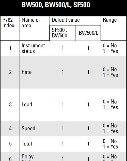
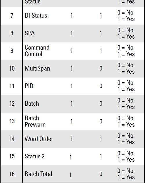
7 Map Element Selection APPLICATION GUIDE P762 Map Element Selection parameter P762 allows you to select what elements to include in the Input and Output Tables. By selecting only the data required, you can reduce the amount of data being transferred over the bus. Notes: P762 should only be modified by an advanced user who wants to limit the amount of data being transferred. See the Profibus DP SmartLinx operating instructions 7ML19981AQ03 Appendix A Reducing the amount of data being transferred over the Bus for more details. Changes do not take effect until after a power cycle. The chart below gives the default values for this parameter. If the default values are used then the configuration and Data Maps in the main body of this guide remain correct. If any of these values are changed, then the Data Maps will be shortened and the configuration will change. Please see the Profibus DP SmartLinx operating instructions 7ML19981AQ03 Appendix A for details on how to use P762. SmartLinx EtherNet/IP AG of 25
8 SmartLinx EtherNet/IP AG of 25
 Identifies the module used.")

9 Module Identification Parameters P794 and P795 are used together to identify the module type and protocol used. P794 SmartLinx Module Type (Read only) Identifies the module used. APPLICATION GUIDE P795 SmartLinx Protocol (Read only) Identifies the protocol used: the value varies according to the module and whether it is a type 1 or type 2. Device Card P794 value P795 value BW500, BW500/L, SF500 AB RIO 1 72 PROFIBUS DP 2 1 DeviceNet 2 37 ProfiNet IO MODBUS TCP/IP EtherNet I/P P634: Communication Totalizer Resolution Parameter P634 is used to set the number of fixed decimal places for Total 1 and Total 2 for SmartLinx communication. SmartLinx EtherNet/IP AG of 25
10 EtherNet/IP APPLICATION GUIDE General EtherNet/IP is based on the Common Industrial protocol (CIP) which is also the application layer for DeviceNet and ControlNet. The module acts as an adapter class product on the EtherNet/IP network. The Input- and Output Data is accessed using I/O connections or Explicit messages towards the Assembly Object and the Parameter Input/Output Mapping Objects. The following port numbers are used for EtherNet/IP communication: Port 2222 (I/O Data) Port (Encapsulated CIP messages) DHCP/BootP The module can retrieve the TCP/IP settings from a DHCP or BootP server. If no DHCP server is found, the module will fall back on it s current settings (i.e. the settings currently stored in \ethcfg.cfg ). If no current settings are available (i.e. ethcfg.cfg is missing, or contains invalid settings), the module will halt and indicate an error on the on-board status LEDs (the settings may however still be accessed using HICP or gleaning, see 3-5 Anybus IPconfig (HICP) and 3-5 ARP Gleaning ). ARP Gleaning The module supports the Address Resolution Protocol (ARP), allowing the IP settings to be altered using the ARP-command on a PC. Syntax: arp -s <IP address> <MAC address> ping <IP address> arp -d <IP address> The arp -s command stores the IP and MAC address in the PCs ARP-table. When the ping -command is issued, the PC will address the module with the new IP address; the module recognizes that it was addressed with the correct MAC address and adopts the new IP address from the ping message. If successful, new settings will be stored in the ethernet configuration file as follows: IP Address: xxx.xxx.xxx.xxx (value supplied in ARP command) Gateway: (no gateway) Subnet: DHCP: OFF Notes: This functionality may cause problems if multiple devices continuously issue ping -messages towards the module. The reason for this lies in the very nature of this functionality; since the module adopts the IP address from all ping -messages, any additional ping -messages may cause the module to change back and forth between old and new settings. Web Server The SmartLinx EtherNet/IP module has an on-board Web server for Network configuring or hosting a custom web site. SmartLinx EtherNet/IP AG of 25

11 Viewing the network settings on the Web server: Open your web browser and enter the IP address of the SmartLinx EtherNet/IP module on your network. The default IP address for the SmartLinx module is Make the desired network changes to your configuration and select the save button to store the configuration. Custom Web site The SmartLinx EtherNet/IP module will allow the user to create a customer web site for the module. Downloading of the site is done using a standard FTP connection to the module. The user name for the FTP login is ABX and the password is FTPAccess. An example website covering some of the functions of the BW500 can be downloaded from the Siemens service and support website. For further information regarding custom web site design for the module can be obtained from: Application Layer This section describes the meaning of data read from and written to the Siemens Milltronics SmartLinx device slave memory. The output words (PLC master Write operation) and input words (PLC master Read operation) are described in the Data Map. Parameter Indexes Most parameters used on Siemens Milltronics SmartLinx devices are indexed. Indexing allows a parameter to relate to more than one input or output. For example, many parameters are indexed by measurement point while others are indexed by relay output or discrete input. The way that indexes are handled in the memory map depends on the data access method used. SmartLinx EtherNet/IP AG of 25
12 Primary Index An index that relates to an input or output is called a Primary Index. Example: P100[3] = 1 means P100 (Relay function) for relay 3 is set to value 1 (Rate alarm) See BW500 operating instructions for details on parameters. APPLICATION GUIDE Data Access Methods There are three different methods used in the memory mapping to give access to the SmartLinx Device parameter table. They are: Direct Access Single Parameter Access (SPA) Direct Access Certain values are mapped directly into words. These words can be monitored continuously but they are not configurable. Single Parameter Access (SPA) This is a hand-shaking method where the PLC specifies: parameter number primary index secondary index decimal place format read/write flag value With this method any value in the Siemens Milltronics product can be read or written. SmartLinx EtherNet/IP AG of 25
13 Using Single Parameter Access (SPA) SPA allows continuous monitoring or demand programming of a parameter. APPLICATION GUIDE Reading a Parameter 1. Set the Read/Write flag in the output table (Write Block) to 0, Read. 2. Write the Parameter Number, Primary Index, Secondary Index, Decimal Place, and Format in the correct locations. Note: If there is no secondary index, then place a 0 in this location. 3. Monitor the Input table of the PLC (Read Block) and watch for the values you wrote to appear in the appropriate locations, then go to Step Read the requested parameter value in the Input table (Read Block). These values are continuously updated. Continue reading from these words until values for other parameters are required. At that time, go back to step 1. Writing a Parameter 1. Set the Read/Write flag in the output table (Write Block) to 0, Read. 2. Write the Parameter Number, Primary Index, Secondary Index, Decimal Place, and Format in the correct locations. 3. Write the new value of the parameter into the correct location of the output memory (Write Block). 4. If the unit is not in program mode, write a 1 to the operating mode word in the output memory (Write Block). Please note that writing a 1 will only work if the word is currently a 0: if not, you need to change it to 0 before writing a 1 so it can take effect. 5. Set the Read/Write flag in the output table (Write Block) to a 1 write. 6. Monitor the Input table of the PLC (Read Block) and watch for the values you wrote to appear in the appropriate locations. 7. Set Read/Write flag back to Place unit in Run mode. Data Map Note: The data maps shown for the Write and Read Blocks apply if P762 is set to the default values. If any of these values is changed, the data map will be shortened and the configuration will change. This section describes the meaning of the data read from and written to the Siemens Milltronics SmartLinx device. SmartLinx EtherNet/IP AG of 25


14 Write Block BW500 and SF500 Note: All the 32 bit numbers (except for the SPA numbers) have a fixed decimal place of 3 digits. For example PID 1 setpoint value of 3,245 is a value of in the BW500 and the SF500. To make a change to any parameter in the BW500 or the SF500 using SmartLinx, P799 Communications Control must be set to 1. SmartLinx EtherNet/IP AG of 25
, see page 24. Primary Index, SPA Specifies the primary index number for the parameter specified by word 0.")
15 BW500/L Note: To make a change to any parameter in the BW500/L using SmartLinx, P799 Communications Control must be set to 1. Parameter, SPA Specifies the parameter number for Single Parameter Access (SPA), see page 24. Primary Index, SPA Specifies the primary index number for the parameter specified by word 0. Secondary Index, SPA Specifies the secondary index for the parameter specified by word 0. This word is ignored for parameters that don t use multiple indexes. New Value, SPA The new value of the specified parameter and index. Decimal Place, SPA This word specifies the number of decimal places for the value in words 3 and 4. Positive values indicate that the decimal place shifts to the left, and negative values indicate that the decimal place shifts to the right. For example: word 5 = 1:all returned values have the decimal place shifted 1 space to the left and a returned value of 5,213 is interpreted as word 5 = 1:a returned value of 5,213 is interpreted as 52,130 Format, SPA This word is always set to 0. Read/Write Flag, SPA This word determines whether the device will allow parameter values to be written. 0 = Read 1 = Write SmartLinx EtherNet/IP AG of 25
 must change state in order to cause the command to begin. For example, to reset totalizer 1, Bit 8 must be cleared to 0, then set to 1.")
16 Command Control, Operational Commands The command control word is used to control the unit. Each bit gives access to a command or state as if the operator was using the keypad. Bits initiating a command (6 to 11) must change state in order to cause the command to begin. For example, to reset totalizer 1, Bit 8 must be cleared to 0, then set to 1. It can stay set or clear for any period. BW500 and SF500 SmartLinx EtherNet/IP AG of 25
 Controls the location of the setpoint. If it is set as local, then the setpoint used is internal to the BW500 or SF500.")
17 BW500/L Bit 00 and 03: PID Mode (BW500 and SF500 only) Sets the mode of PID control to either manual (output determined by P410 PID Manual) or auto (output determined by PID control in device). Bit 02 and 05 Setpoint Source (BW500 and SF500 only) Controls the location of the setpoint. If it is set as local, then the setpoint used is internal to the BW500 or SF500. If the setpoint source is set to remote, then the setpoint is controlled by a ma input. For setpoint control through communications this must be set to local. Bit 01 and 04: Freeze (BW500 and SF500 only) Suspends PID function when PID Mode = 1 (auto) and holds the output at the last value. PID functionality resumes when the freeze bit is cleared. Bit 06: Zero Sets the zero point for calibration of the belt scale. This is a momentary setting that must be reset to 0 once the input is accepted. To check that the input was accepted read word 0, bit 7 (zero status) and ensure it shows 1. Once it shows a 1 then reset this bit to 0. Bit 07: Span Sets the span for calibration of the belt scale. This is a momentary setting that must be reset to 0 once the input is accepted. To check that the input has been accepted, read word 0, bit 8 (Span Status) and ensure it shows a 1. Once it shows 1 then reset this bit to 0. Bit 08: Reset Totalizer 1 Causes the internal totalizer 1 to be reset to 0. This is a momentary setting that must be reset to 0 once the input is accepted. To reset this back to 0, the use of a timer is recommended. SmartLinx EtherNet/IP AG of 25
18 Bit 09: Reset Totalizer 2 Causes the internal totalizer 2 to be reset to 0. This is a momentary setting that must be reset to 0 once the input is accepted. To reset this back to 0, the use of a timer is recommended. Bit 10: Reset Batch Totalizer (BW500 and SF500 only) Causes the batch totalizer to be reset to 0. This is a momentary setting that must be reset to 0 once the input is accepted. To reset this back to 0, the use of a timer is recommended. Bit 11: Print Starts print operation. One of the communications ports on your Milltronics Integrator must be configured for a printer. This is a momentary setting that must be reset to 0 once the input is accepted. To reset this back to 0, the use of a timer is recommended. Multispan Selection (BW500 and SF500) Sets the current span (1 to 4). Any parameters that relate to span will use this value to determine which span is referenced. See the operating instructions for the BW500 or SF500 for more information on multispan. PID Setpoints (BW500 and SF500 only) Contain the current setpoint values as P415 in the Milltronics BW500 or SF500. To write these setpoints bits 02 and 05 in word 8 - Control must be set to local. Batch Setpoint (BW500 and SF500 only) Contain the current setpoint value as P564 in the Milltronics BW500 or SF500. Batch Prewarn Setpoint (BW500 and SF500 only) Contain the current setpoint value as P567 in the Milltronics BW500 or SF500. Word Order This word controls which word comes first in the UINT32 integers. For a value 0, the most significant word is given first. For a value 1, the least significant word is given first. 0 = MSW first 1 = LSW first Read Block Values returned in the words in the Read are in response to the Write to the Siemens Milltronics SmartLinx device. Words 0 through 20 have values with fixed meanings and formats. This means that you do not have to start communications with a Write in order to use Read, the data is always there. Words 22 through 29 are values returned in response to writing words 0 through 7 for Single Parameter Access (SPA), see Write Block on page 14. SmartLinx EtherNet/IP AG of 25


19 BW500 and SF500 SmartLinx EtherNet/IP AG of 25

20 BW500/L Instrument Status 1 This word is used to feed back the current operating state of the product. Each bit gives the state of different parts of the product, some mutually exclusive, others are not. The state should be checked to verify operation. SmartLinx EtherNet/IP AG of 25

21 BW500 and SF500 SmartLinx EtherNet/IP AG of 25
22 BW500/L Bits 0 to 5: PID Status (BW500 and SF500 only) These bits give the status of the product. For example Bit 0 is the mode of the PID 1 controller (if used). It indicates whether the PID is in manual or auto modes. Bit 6: Zero Status Indicates whether the unit is currently performing a Zero calibration. Bit 7: Span Status Indicates whether the unit is currently performing a Span calibration. Bits 8 to 11: Totalizer Status Indicate 1 if the reset totalizer or print operations are taking place. (These are momentary and will only stay set for a very short period.) (Note: Bit 10 applies only to BW500 and SF500.) Bit 12: Write Privileges Indicates whether the PLC can write parameters/commands to the product. This is controlled by parameter P799. P799 = 1 PLC may change the Siemens Milltronics SmartLinx device parameters. P799 = 0 PLC can only read. Bit 13: Configuration Status Indicates whether the unit is configured (all required parameters have been entered). Bit 14: Program Mode Indicates program (calibration) mode: 0 = PROGRAM mode 1 = RUN mode Bit 15: Totalizing Status Indicates whether the unit is totalizing. SmartLinx EtherNet/IP AG of 25
 Load Contains the current load reading in engineering units. (For a full description of this reading, please refer to your Milltronics Integrator operating instructions.")
23 Rate Contains the current rate reading in engineering units. (For a full description of this reading, please refer to your Milltronics Integrator operating instructions.) Load Contains the current load reading in engineering units. (For a full description of this reading, please refer to your Milltronics Integrator operating instructions.) Speed Contains the current speed reading in engineering units. (For a full description of this reading, please refer to your Milltronics Integrator operating instructions.) Total 1 (The number of fixed decimal places for this value is controlled by P634 primary indexes 1 and 2. The default setting is 3.) Contains the current value for totalizer 1 in engineering units. (For a full description of this reading, please refer to your Milltronics Integrator operating instructions.) Total 2 (The number of fixed decimal places for this value is controlled by P634 primary indexes 1 and 2. The default setting is 3.) Contains the current value for totalizer 2 in engineering units. (For a full description of this reading, please refer to your Milltronics Integrator operating instructions.) Relay Status Shows the current logical status of all relays. 0 = relay not asserted 1 = relay asserted Asserted indicates that the function controlling the relay is in an active state. Relay contacts can open or close based on this state, see your device operating instructions for details. Discrete Input Status Shows the current logical status of all discrete inputs. 0 = discrete input open 1 = discrete input closed Multispan Selection (BW500 and SF500 only) Shows the currently selected span (1 to 4). PID 1 Setpoint Value (BW500 and SF500 only) Contains the current setpoint value for PID 1 in engineering units. (For a full description of this reading, please refer to your Milltronics Integrator operating instructions.) SmartLinx EtherNet/IP AG of 25
24 PID 2 Setpoint Value (BW500 and SF500 only) Contains the current setpoint value for PID 2 in engineering units. (For a full description of this reading, please refer to your Milltronics Integrator operating instructions.) Batch Setpoint Value (BW500 and SF500 only) Contains the value of P564 Batch Setpoint. (For a full description of this parameter, please refer to your Milltronics Integrator operating instructions.) Batch Prewarn Setpoint Value (BW500 and SF500 only) Contains the value of P567: Batch Prewarn Setpoint. (For a full description of this parameter, please refer to your Milltronics Integrator operating instructions.) Parameter Number / Primary Index / Secondary Index, SPA; Decimal Place / Format / Read/Write flag, SPA These words contain the last values written to words 0 to 2 and words 5 to 7 of the Write area. They confirm that the parameter value has been written. These words are not updated until the value has been successfully transferred and stored in the Siemens Milltronics SmartLinx device. Use these words as an indicator that the requested information has been updated. Value, SPA The returned value of the specified parameter and index. Word Order The placement of the most significant word (MSW). 0 = MSW first 1 = MSW second Instrument Status 2 This word is used to feed back the current operating state of the product. Each bit gives the state of different parts of the product, some mutually exclusive, others are not. The state should be checked to verify operation. Bits 0 Totalizer 1 overflow If Totalizer 1 has overflowed (that is, has exceeded the spaces available in SmartLinx), this bit is set. The overflow condition can be changed by reducing Communication Totalizer resolution (P634). Bit 1 Totalizer 2 overflow If Totalizer 2 has overflowed (that is, has exceeded the spaces available in SmartLinx), this bit is set. The overflow condition can be changed by reducing Communication Totalizer resolution (P634). Batch Totalizer (BW500 and SF500 only) Contains the current value for the Batch Totalizer in engineering units. (For a full description of this reading, please refer to your Milltronics Integrator operating instructions.) Data Types The Siemens Milltronics SmartLinx device parameters take on many values in various formats, as discussed in the Siemens Milltronics SmartLinx device operating instructions. For the convenience of the programmer, those values are converted to and from 16-bit integer numbers, since those are easily handled by most PLCs. SmartLinx EtherNet/IP AG of 25
25 Integer Integers used on the Mass Dynamics products can have any valid value. So, the entire range from 32,768 to 32,767 or 0 to 65,535 is available and no values are used as error conditions. Bit Values Bits are packed into registers in groups of 16 bits (1 word). In this guide bits are numbered from 00 to 15, with bit 00 referring to the least significant bit and bit 15 referring to the most significant bit. Unsigned Double Precision Integer (UINT32) Large numbers are put into unsigned 32-bit integers. By default they are set up so that the first word (register) is the most significant word (MSW) and the second word (register) is the least significant word (LSW) depending on the setting of the word order bit. For example, when reading words 7 and 8 on the Mass Dynamics block (Total 1), the 32 bits would look as follows: The whole is read as a 32-bit integer. Troubleshooting Generally In all cases, first check P794 and P795, to verify that you have the correct card for your device. Next check that the SmartLinx module has passed its on-going built-in self test (Siemens Milltronics SmartLinx device parameter P790). The result should be pass. If fail is indicated, either the module is defective, or the module connector on the Siemens Milltronics SmartLinx device is defective. If err1 is indicated, the Siemens Milltronics software doesn t recognize the ID number of the installed module. Please contact Siemens Milltronics or your distributor for instructions and/or upgraded Siemens Milltronics SmartLinx device software. Make sure the Siemens Milltronics device is set to a unique address, and does not conflict with any other slave(s) on the bus. Check the configuration of the scanning master, and make sure it is functioning properly. 1. If you have configured the Siemens Milltronics device in the Master and downloaded it to the processor, but the device is not coming online: Check the cable to the card. In particular, check that it is not damaged in any way, verify that it is a functioning cable. Verify that you set the correct IP address on the card. Verify that the Read and Write Block sizes are correct. This is particularly important if you are using P762. Technical Support or Product Feedback For product feedback or technical support, please contact your local Siemens Milltronics representative or us at SmartLinx EtherNet/IP AG of 25
Communication settings: Network configuration can be done via the Anybus IP configuration setup tool or via the on board Web server
 SmartLinx EtherNet/IP instruction and use APPLICATION GUIDE Objective: Show the user how to configure and use an EtherNet/IP SmartLinx communication module. AG082415 While every effort was made to verify
Instruction Manual February smartlinx interface module PROFIBUS-DP
 Instruction Manual February 2003 R smartlinx interface module PROFIBUS-DP Safety Guidelines Warning notices must be observed to ensure personal safety as well as that of others, and to protect the product
SMARTLINX INTERFACE MODULE
 SMARTLINX INTERFACE MODULE FOR DEVICE NET Instruction Manual PL-583 April 2001 R 33455830 Rev. 1.1 Safety Guidelines Warning notices must be observed to ensure personal safety as well as that of others,
SMARTLINX INTERFACE MODULE
 SMARTLINX INTERFACE MODULE FOR DEVICE NET Instruction Manual December 2001 R Safety Guidelines Warning notices must be observed to ensure personal safety as well as that of others, and to protect the product
SMARTLINX INTERFACE MODULE
 SMARTLINX INTERFACE MODULE FOR ALLEN-BRADLEY REMOTE I/O Instruction Manual December 2001 R Safety Guidelines Warning notices must be observed to ensure personal safety as well as that of others, and to
Interface Module. for Allen-Bradley Remote I/O. Instruction Manual PL-533 May Rev 3.0
 Interface Module for Allen-Bradley Remote I/O Instruction Manual PL-533 May 2000 33455330 Rev 3.0 Ultrasonic level Radar At Milltronics, we endeavour to design equipment that is simple to use and reliable
MARTLINX INTERFACE MODULE
 SMARTLINX INTERFACE MODULE FOR PROFIBUS-DP Instruction Manual December 2001 R MARTLINX INTERFACE MODULE Safety Guidelines Warning notices must be observed to ensure personal safety as well as that of others,
Disclaimer of Liability
 Safety Guidelines: Warning notices must be observed to ensure personal safety as well as that of others, and to protect the product and the connected equipment. These warning notices are accompanied by
Interface Module for Allen-Bradley Remote I/O Instruction Manual PL-533 September 1999
 Interface Module for Allen-Bradley Remote I/O Instruction Manual PL-533 September 1999 33455330 Rev 2.0 Ultrasonic level Radar At Milltronics, we endeavour to design equipment that is simple to use and
Instruction Manual March smartlinx interface module REMOTE I/O
 Instruction Manual March 2004 R smartlinx interface module REMOTE I/O Safety Guidelines Warning notices must be observed to ensure personal safety as well as that of others, and to protect the product
Instruction Manual June smartlinx module DEVICENET
 Instruction Manual June 2008 R smartlinx module DEVICENET Safety Guidelines: Warning notices must be observed to ensure personal safety as well as that of others, and to protect the product and the connected
Disclaimer of Liability
 Safety Guidelines: Warning notices must be observed to ensure personal safety as well as that of others, and to protect the product and the connected equipment. These warning notices are accompanied by
While every effort was made to verify the following information, no warranty of accuracy or usability is expressed or implied.
 AG090115 How to configure SIMATIC STEP7 V5.5 to read cyclic data from Objective: To use Siemens SIMATC S7300 PLC to read data from MultiRanger/HydroRanger 200 HMI through SmartLinx PROFIBUS communication
Output Interfaces for SVS2000 TM Installation & Operation Manual
 IOM Output Interfaces for SVS2000 TM Installation & Operation Manual Output Interfaces for SVS2000 TM Installation & Operation Manual CONTENTS I. INTRODUCTION... 1 II. INSTALLING THE OUTPUT INTERFACE...
DEFAULT IP ADDRESS
 REAL TIME AUTOMATION 2825 N. Mayfair Rd. Suite 111 Wauwatosa, WI 53222 (414) 453-5100 www.rtaautomation.com EtherNet/IP - DeviceNet Master Gateway MODBUS TCP - DeviceNet Master Gateway Copyright 2007 Real
How to Configure the Allen Bradley CompactLogix for EtherNet/IP Communications to MultiRanger/ HydroRanger 200 HMI
 How to Configure the Allen Bradley CompactLogix for EtherNet/IP Objective: Show the user how to configure the CompactLogix for Ethernet/IP communications to MultiRanger 200 HMI or. AG071416 Equipment PC
Instruction Manual February smartlinx interface module MODBUS RTU
 Instruction Manual February 2004 smartlinx interface module MODBUS RTU Safety Guidelines Warning notices must be observed to ensure personal safety as well as that of others, and to protect the product
Quick Start Manual G2-2 Series with Ethernet Interface
 Getting Started This is a brief document designed to quickly get you started setting up your valve manifold with integrated G2-2 series EtherNet/IP communication protocol. 1) Initial Unpacking and Inspection
Communication. SmartLinx PROFIBUS DP-V1. Operating Instructions
 Communication SmartLinx PROFIBUS DP-V1 Operating Instructions Edition 08/2015 Safety Guidelines: Warning notices must be observed to ensure personal safety as well as that of others, and to protect the
ENVIRORANGER ERS 500 NVIRORANGER ERS 500 COMMUNICATIONS REFERENCE. Instruction Manual August 2001
 ENVIRORANGER ERS 500 COMMUNICATIONS REFERENCE Instruction Manual August 2001 NVIRORANGER ERS 500 Safety Guidelines Warning notices must be observed to ensure personal safety as well as that of others,
GSE Scale Systems Ethernet IP Option
 AN SPX BRAND GSE Scale Systems Ethernet IP Option Option P/N 24660B-421C0 Revision 0.51 Apr 3, 2008 Page 1 of 27 TABLE OF CONTENTS 1. INTRODUCTION...5 1.1 Overview...5 1.2 Definiti ons...5 1.3 Reference
GW-7472 / GW EtherNet/IP to Modbus RTU/TCP Gateway User Manual
 GW-7472 / GW-7473 EtherNet/IP to Modbus RTU/TCP Gateway User Manual Warranty All products manufactured by ICP DAS are under warranty regarding defective materials for a period of one year, starting from
P2 Configuration Guide
 P2 Configuration Guide March 2018 Rev. 4.00 #220, 550 71 st Avenue SE Calgary, Alberta, Canada T2H 0S6 Phone: (403) 255-9544 Fax: (403) 259-2343 www.barnettprotalk.com E-mail: sales@barnettprotalk.com
EnviroRanger ERS 500 Communications Reference PL-558 Nov. 1999
 EnviroRanger ERS 500 Communications Reference PL-558 Nov. 1999 33455580 Rev 2.0 Ultrasonic level Radar At Milltronics, we endeavour to design equipment that is simple to use and reliable in its operation,
M3-61D EtherNet/IP Slave Module. M3-61D EtherNet/IP TM Slave Module CONTROL TECHNOLOGY CORPORATION
 CONTROL TECHNOLOGY CORPORATION M3-61D EtherNet/IP TM Slave Module M3-61D EtherNet/IP Slave Module Copyright 2008 All Rights Reserved. Blank 2 WARNING: Use of CTC Controllers and software is to be done
Instruction Manual Power Distribution System SVS16-PN-XX
 Instruction Manual Power Distribution System SVS16-PN-XX 2 Contents 1 General...4 1.1 General mounting guidelines...4. 2 Bus-capable power distribution system SVS16-PN-XX...5 2.1. Overview...5 2.2. Schematic
Tritex II EtherNet/IP - Option
 Tritex II EtherNet/IP - Option Tritex II Ethernet/IP Option.doc 10/15/13 REV B 952-368-3434 Tritex II EtherNet/IP Option.doc 2 10/15/13 Contents 1. General... 5 1.1. IP Address... 6 1.2. Network Classes...
How to configure an Anybus Modbus-TCP slave module with Unity Pro L
 How to configure an Anybus Modbus-TCP slave module with Unity Pro L HMS Industrial Networks AB Page 1 (25) Document history Revision Date Description Author 1.00 2007-06-20 Created Thorbjörn Palm 1.01
G5 Weighing Instrument
 G5 Weighing Instrument Program version 1.4.X Fieldbus Option Manual PM and RM types CONTENTS 1. Introduction... 1-1 General... 1-1 Module installation... 1-2 Ordering information... 1-3 2. Modules...
Servo press kit YJKP - Host interface
 Application Note Servo press kit YJKP - Host interface Host interface of the servo press kit YJKP: - Communication possibilities - Workflow - Object directory - Communication protocol - Communication Mobus
Instruction Manual Power Distribution System SVS16-EN-XX
 Instruction Manual Power Distribution System SVS16-EN-XX 2 Contents 1 General...4 1.1 General mounting guidelines...4. 2 Bus-capable power distribution system SVS16-EN-XX...5 2.1. Overview...5 2.2. Schematic
Addendum to Verbatim Gateway Owner's Manual. Gateway Ethernet Module Setup. Version 5.0
 Addendum to Verbatim Gateway Owner's Manual Gateway Ethernet Module Setup Version 5.0 Revision History Rev # Description Author/Editor Date 3 Draft. Re-write of 2.0 Davey Hudson 4/10/2015 4 Draft. Re-write
ENVIRORANGER ERS 500 NVIRORANGER ERS 500 USER GUIDE. Instruction Manual PL-600 January Rev. 1.2
 ENVIRORANGER ERS 500 USER GUIDE Instruction Manual PL-600 January 2001 33456000 Rev. 1.2 NVIRORANGER ERS 500 Safety Guidelines Warning notices must be observed to ensure personal safety as well as that
1) Examine exterior of package for signs of damage. Report any damage to shipping carrier.
 Examine exterior of package for signs of damage. Report any damage to shipping carrier.") I P MAC AD D RE S S Getting Started This is a brief document designed to quickly get you started setting up your valve manifold with an integrated Numatics G2-2 Series EtherNet/IP communication node. 1)
I P MAC AD D RE S S Getting Started This is a brief document designed to quickly get you started setting up your valve manifold with an integrated Numatics G2-2 Series EtherNet/IP communication node. 1)
Allen-Bradley. PowerFlex DSI Communication Adapters. DeviceNet (22-COMM-D) EtherNet/IP (22-COMM-E) PROFIBUS (22-COMM-P) RS-232 DF1 Module (22-SCM-232)
 EtherNet/IP (22-COMM-E) PROFIBUS (22-COMM-P) RS-232 DF1 Module (22-SCM-232)") Communications PowerFlex DSI Communication Adapters DeviceNet (22-COMM-D) EtherNet/IP (22-COMM-E) PROFIBUS (22-COMM-P) RS-232 DF1 Module (22-SCM-232) Communications 22-COMM-D DeviceNet Adapter The PowerFlex
Communications PowerFlex DSI Communication Adapters DeviceNet (22-COMM-D) EtherNet/IP (22-COMM-E) PROFIBUS (22-COMM-P) RS-232 DF1 Module (22-SCM-232) Communications 22-COMM-D DeviceNet Adapter The PowerFlex
SE-330 SERIES (NEW REVISION) MODBUS/TCP INTERFACE
 MODBUS/TCP INTERFACE") Tel: +1-800-832-3873 E-mail: techline@littelfuse.com www.littelfuse.com/se-330 SE-330 SERIES (NEW REVISION) MODBUS/TCP INTERFACE Revision 0-E-121117 Copyright 2018 Littelfuse Startco Ltd. All rights reserved.
Tel: +1-800-832-3873 E-mail: techline@littelfuse.com www.littelfuse.com/se-330 SE-330 SERIES (NEW REVISION) MODBUS/TCP INTERFACE Revision 0-E-121117 Copyright 2018 Littelfuse Startco Ltd. All rights reserved.
DeltaV Virtual IO Module Network Gateway
 DeltaV Virtual IO Module Redundant DeltaV Virtual IO Modules providing a Plant Ethernet Network Gateway for a DeltaV Controller Easy to use Powerful Integration Solution Modular, Flexible Package Introduction
HART / EtherNet/IP Gateway GT200-HT-EI User Manual V 1.0 REV A SST Automation
 HART / EtherNet/IP Gateway GT200-HT-EI V 1.0 REV A SST Automation E-mail: SUPPORT@SSTCOMM.COM WWW.SSTCOMM.COM Catalog 1 Product Overview... 4 1.1 Product Function...4 1.2 Product Features... 4 1.3 Technical
FNL Modbus TCP Interface
 FNL Modbus TCP Interface Users Manual V0.1 17.06.2009 Project No.: 5304 Doc-ID.: FNL Modbus TCP Interface-UM-V0.1 Status: Released COMSOFT d:\windoc\icp\doku\hw\fnl\modbus tcp\version_0.1\fnl_modbus_tcp_e.doc
BridgeWay. Ethernet to DeviceNet Gateway User Manual. Part No. AB7603. Publication PUB-AB
 BridgeWay Ethernet to DeviceNet Gateway User Manual Part No. AB7603 Pyramid Solutions 1850 Research Drive, Suite 300 Troy, Michigan 48083 Phone 248-524-3890 Web www.pyramid-solutions.com Publication PUB-AB7603-008
Table of Contents. Chapter 1: Getting Started. Chapter 2: Specifications
 Chapter 1: Getting Started Introduction...1-2 Conventions Used...1-3 What s in the Box?...1-4 Getting Started...1-5 Before You Begin......1-6 Step 1 - Install Configuration Software...1-7 Step 2 - Launch
Application Note: 105U/905U-G-ET1 EtherNet IP & CompactLogix PLC
 Y ELPRO Technologies Pty Ltd Application Note: 105U/905U-G-ET1 EtherNet IP & CompactLogix PLC PURPOSE The purpose of this document is to provide the reader with an application note for using an Allen Bradley
Anybus X-gateway. PROFINET IRT (2.32) Interface NETWORK GUIDE
 Interface NETWORK GUIDE") Anybus X-gateway PROFINET IRT (2.32) Interface NETWORK GUIDE SCM-1202-028-EN 1.1 ENGLISH Important User Information Liability Every care has been taken in the preparation of this document. Please inform
Anybus X-gateway PROFINET IRT (2.32) Interface NETWORK GUIDE SCM-1202-028-EN 1.1 ENGLISH Important User Information Liability Every care has been taken in the preparation of this document. Please inform
EL731 PROFIBUS INTERFACE
 Tel: +1-800-832-3873 E-mail: techline@littelfuse.com www.littelfuse.com/el731 EL731 PROFIBUS INTERFACE Revision 0-A-032816 Copyright 2016 Littelfuse Startco All rights reserved. Document Number: PM-1011-EN
Additional instructions Videographic recorder LINAX DR3000. EtherNet/IP Adapter
 Additional instructions Videographic recorder LINAX DR3000 EtherNet/IP Adapter Table of contents: 1 General information... 4 1.1 Registered trademarks... 4 1.2 Firmware history... 4 1.3 Scope of delivery...
EGW1-IA3-MB User s Manual
 www.exemys.com Rev. 0 1 Products are in constant evolution to satisfy our customer needs. For that reason, the specifications and capabilities are subject to change without prior notice. Updated information
Contents User Manual For PIM
 PIM User Manual 503287 - User Manual For PIM Contents 1. Introduction... 3 2. Navigate this Document... 3 3. Safety Summary... 4 4. Trademarks and Copyrights... 4 5. Contact Information... 5 6. Documentation
AP-ENBD User Manual V0.2
 AP-ENBD User Manual V0.2 2015/12 Catolog Catolog... 2 1 Introduction... 1 1.1 Communication Structure... 1 1.2 Internal Principle... 2 2 Installation... 2 2.1 Connect to the Same Router (or Switch )...
WebAccess Driver Configuration Manual
 WebAccess AB MicroLogix 1400 ABDrv.DLL Driver date: 2015/3/30 English Version 1.1 Revision History Date Version Author Reviewer Description 2018-10-29 1.0 Alger.Tan ChiRen.Wei Initial Release 2018-11-2
BridgeWay. Ethernet to DeviceNet Gateway User Manual. Part No. AB7603 For Firmware Revision and Later. Publication PUB-AB
 BridgeWay Ethernet to DeviceNet Gateway User Manual Part No. AB7603 For Firmware Revision 2.03.01 and Later Pyramid Solutions, Inc. 30150 Telegraph Road, Suite 200 Bingham Farms, Michigan 48025 Phone 248-549-1200
Release Notes. Flexi Soft. Gateways Release Notes. The modular safety controller that cleverly incorporates advantages
 Release Notes Flexi Soft Gateways Release Notes The modular safety controller that cleverly incorporates advantages Overview gateways Type Description Current version Page FX0-GPNT PROFINET IO gateway
User Manual Gateway component for EtherNet/IP
 User Manual Gateway component for EtherNet/IP PR100066 1/7/2016 Table of Contents KUNBUS GmbH Table of Contents 1 General Information... 3 1.1 Disclaimer... 3 1.2 Notes Regarding this User Manual... 4
Version 1.4. January Publication CNIP-1000
 Version 1.4 January 2016 Publication CNIP-1000 ConveyLinx module firmware and functionality is protected by U.S. and international patents. For complete patent information visit www.pulseroller.com/patents
X-gateway Interface Addendum DeviceNet Scanner Interface
 X-gateway Interface Addendum DeviceNet Scanner Interface Rev. 1.10 HMS Industrial Networks AB Germany Japan Sweden U.S.A + 49-721 - 96472-0 + 81-45 - 478-5340 + 46-35 - 17 29 20 + 1-773 - 404-3486 ge-sales@hms-networks.com
MicroLogix 1100 Programmable Controllers FRN 16
 Release Notes MicroLogix 1100 Programmable Controllers FRN 16 Catalog Numbers 1763-L16AWA, 1763-L16BWA, 1763-L16BBB, 1763-L16DWD Topic Page Enhancements 2 Corrected Anomalies 5 Additional Resources 9 About
EtherNet /IP. Interface Configuration Quick Start
 EtherNet /IP Interface Configuration Quick Start Trademark Notices Comtrol, DeviceMaster, and PortVision are registered trademarks of Comtrol Corporation. ControlLogix, PLC-5 and Rockwell Automation are
Description of options. user s manual. DEIF A/S Frisenborgvej 33 DK-7800 Skive Tel.: Fax:
 Description of options TCP/IP Ethernet module user s manual DEIF A/S Frisenborgvej 33 DK-7800 Skive Tel.: +45 9614 9614 Fax: +45 9614 9615 info@deif.com www.deif.com Document no.: 4189320029B Legal information
Du line. Dupline Field- and Installationbus Dupline Ethernet Modbus/TCP Gateway Type G G Type Selection
 Dupline Field- and Installationbus Dupline Ethernet Modbus/TCP Gateway Type G 3891 0052 Built-in Dupline channel generator Modbus/TCP Slave 10 and 100 Mbit operation, full or half duplex Twisted pair cables
PRELIMINARY DESCRIPTION
 Modbus TCP to Relay output and 8 Digital inputs. Phone: +1 561 779 5660 email:datexel@datexel.com www.datexel.com User Guide MODBUS TCP/IP protocol Firmware Version : 80 PRELIMINARY DESCRIPTION Modbus
DeviceNet Expansion Board
 DeviceNet Expansion Board Catalog No. EXBD05 Installation and Operating Manual 10/02 Table of Contents Section 1 General Information................................................... 1 1 Introduction.......................................................
Remote I/O ALLEN-BRADLEY Remote I/O Interface for IQ plus 310A and IQ plus 800/810 Indicators
 Remote I/O ALLEN-BRADLEY Remote I/O Interface for IQ plus 310A and IQ plus 800/810 Indicators Version 2.04 Installation and Programming Manual 36254 Contents About This Manual... 1 1.0 Introduction...
Sherpa R-IN32M3 EtherNet/IP adapter communication stack for Renesas Electronics Corporation s R-IN32M3 series industrial Ethernet controller
 Sherpa R-IN32M3 EtherNet/IP adapter communication stack for Renesas Electronics Corporation s R-IN32M3 series industrial Ethernet controller Technical reference Sherpa LLC http://sherpa-tech.jp Version
CVIC II - CVIL II - CVIR II - MULTICVIL II - Memory Mapping - Manual
 1/36 CVIC II - CVIL II - CVIR II - MULTICVIL II - Memory Mapping - Manual N - Copyright 2011, St Herblain France All rights reserved. Any unauthorized use or copying of the contents or part thereof is
Gateway 1400 Reference Manual
 Profibus-DP Gateway 1400 Reference Manual Copyright All Rights Reserved. No part of this document may be copied, reproduced, republished, uploaded, posted, transmitted, distributed, stored in or introduced
MPCR Series DeviceNet Technical Manual TDMPCRDNTM2-0EN 01/08 Subject to change without notice
 MPCR Series DeviceNet Technical Manual Table of Contents MPCR Series Introduction... 3 Product Overview... 3 About DeviceNet... 4 Overview... 4 MPCR DeviceNet Features... 4 Cabling and Drop Line Lengths
Quick Start Guide NETL ink Ethernet Gateways
 Version en as of FW. Quick Start Guide NETL ink Ethernet Gateways www.helmholz.com Content. Introduction. Checking the Network Situation. Preparing the NETL ink. IP Address Settings on the PG/PC Network
Series SD6 Limit with DeviceNet
 Series SD6 Limit with DeviceNet DeviceNet Communications This appendix describes the DeviceNet protocol as it is implemented in the Series SD6 controller. It primarily describes the objects and attributes
Ethernet/IP Module. User Manual. Contents
 User Manual Contents 1 Important User Information... 2 2 Installation... 3 3 Connection... 4 4 Device Configuration... 5 5 Operation... 8 6 Packet Structures... 9 7 Network Design... 18 8 Specifications...
HART/ Modbus TCP Gateway GT200-HT-MT User Manual V 1.2 REV A SST Automation
 HART/ Modbus TCP Gateway GT200-HT-MT User Manual V 1.2 REV A SST Automation E-mail: SUPPORT@SSTCOMM.COM WWW.SSTCOMM.COM Catalog 1 Product Overview... 4 1.1 Product Function...4 1.2 Product Features...
User Manual Anybus Communicator for EtherNet/IP
 User Manual Anybus Communicator for EtherNet/IP Doc. Id. SCM-1200-096 Rev. 3.02 Connecting Devices TM HMS Industrial Networks Mailing address: Box 4126, 300 04 Halmstad, Sweden Visiting address: Stationsgatan
Version 5.0. Includes ERSC Firmware Version 4.25 and Version 5.2. March Publication ERSC-1500
 Version 5.0 Includes ERSC Firmware Version 4.25 and Version 5.2 March 2016 Publication ERSC-1500 ConveyLinx module firmware and functionality is protected by U.S. and international patents. For complete
EN7000 & Anybus Communicator EIP/MODBUS-RTU user guide 1
 EN7000 & Anybus Communicator EIP/MODBUS-RTU user guide 1 This document describes how to use the HMS Anybus Communicator (ABC) with an EN7000 to control the I/O via EtherNetIP (EIP). The ABC is a gateway
Programmable Set for Simple I/O Communication via Ethernet Modbus/TCP in IP20 TI-BL20-PG-EN-S-6
 CoDeSys-programmable acc. to IEC 61131-3 Cable max. 50 m between interface and read/write head 10/100 Mbps LEDs for display of supply voltage, group and bus errors as well as status and diagnostics Connection
PRELIMINARY DESCRIPTION. (*)Coil (Hex) 0x00A1 0x00A2 0x00A3
Coil (Hex) 0x00A1 0x00A2 0x00A3") DigitalinputtoEthernet Phone: +1 561 779 5660 email:datexel@datexel.com www.datexel.com User Guide MODBUS TCP/IP protocol Firmware Version : 8200 PRELIMINARY DESCRIPTION Modbus TCP/IP server 16 Digital
DigitalinputtoEthernet Phone: +1 561 779 5660 email:datexel@datexel.com www.datexel.com User Guide MODBUS TCP/IP protocol Firmware Version : 8200 PRELIMINARY DESCRIPTION Modbus TCP/IP server 16 Digital
PROFIBUS DP/CAN Gateway PCA-100. User Manual
 PCA-100 REV 4.0 SiboTech Automation Co., Ltd. Technical Support: 021-5102 8348 E-mail: support@sibotech.net Catalog 1 Introduction... 2 1.1 About This Instruction... 2 1.2 Copyright... 2 1.3 Related Products...
EtherNet/IP. Interface for 520 and 920i Indicators. Installation and Programming Manual
 EtherNet/IP Interface for 520 and 920i Indicators Installation and Programming Manual 88537 Contents About This Manual... 1 1.0 Introduction... 1 2.0 Installation... 2 2.1 Installing the EtherNet/IP Interface...................................................
SK CU4-EIP-C Part number:
 SK CU4-EIP-C Part number: 275 271 519 EtherNet/IP Internal Bus Interface The bus interface may only be installed and commissioned by qualified electricians. An electrician is a person who, because of their
Motortronics VirtualSCADA VS2-MT Communication Gateway VS2-MT User Manual Revision
 Motortronics VirtualSCADA VS2-MT Communication Gateway VS2-MT User Manual Revision 1.03.00 Motortronics / Phasetronics 1600 Sunshine Drive Clearwater, Florida 33765 Tel: 727-573-1819 Fax: 727-573-1803
Serial to Ethernet Converter
 Serial to Ethernet Converter User s Manual Version 1.1 2004 Infosystem Technology Corporation Disclaimers The information in this manual has been carefully checked and is believed to be accurate. Infosystem
1. Introduction. Be sure to read the release notes in section 10 before operating the Unit.
 1. Introduction This manual describes the ways of configuring and monitoring the operation of the PROFINET IO Controller CJ1W-PNT Sample Version V0.00 V67.06 V0.00 (Internal release V6.29). Be sure to
BIET EtherNet Interface
 BIET EtherNet Interface Preliminary Release Notes are used to call attention to information that is significant to the understanding and operation of equipment. This BALOGH manual is based on information
BridgeWay. Ethernet to J1939 Gateway User Manual. Part No. AB7645. Publication PUB-AB
 BridgeWay Ethernet to J1939 Gateway User Manual Part No. AB7645 Pyramid Solutions 30150 Telegraph Road, Suite 200 Bingham Farms, Michigan 48025 Phone 248-549-1200 Web www.pyramid-solutions.com Publication
MPCR Series DeviceNet Technical Manual
 MPCR Series DeviceNet Technical Manual Table of Contents MPCR Series Introduction...3 Product Overview...3 About DeviceNet...4 Overview...4 MPCR DeviceNet Features...4 Cabling and Drop Line Lengths (as
ICC. EtherNet/IP Client Driver Manual INDUSTRIAL CONTROL COMMUNICATIONS, INC Industrial Control Communications, Inc.
 INDUSTRIAL CONTROL COMMUNICATIONS, INC. EtherNet/IP Client Driver Manual October 30, 2014 2014 Industrial Control Communications, Inc. TABLE OF CONTENTS 1 EtherNet/IP Client... 2 1.1 Overview... 2 1.2
User Manual APAX Software Manual
 User Manual APAX-5072 Software Manual Copyright The documentation and the software included with this product are copyrighted 2010 by Advantech Co., Ltd. All rights are reserved. Advantech Co., Ltd. reserves
MB40 & MB45 MODBUS TCP/IP Gateway Handbook
 MB40 & MB45 MODBUS TCP/IP Gateway Handbook Version 1.2 29 July 2014 Environdata Australia Pty Ltd 42-44 Percy Street Warwick Queensland 4370 Australia Phone: (07) 4661 4699 Fax: (07) 4661 2485 International
ACS Stepper _10_Modbus LINEAR SOLUTIONS MADE EASY
 MODBUS RTU & TCP PROGRAMMER S GUIDE ACSI ACS Stepper ACS Servo 3600-4169_10_Modbus LINEAR SOLUTIONS MADE EASY Tolomatic reserves the right to change the design or operation of the equipment described herein
Operating a Power Xpert C445 Global Motor Management Relay with a Rockwell PLC via Ethernet/IP
 Operating a Power Xpert C445 Global Motor Management Relay with a Rockwell PLC via Ethernet/IP Introduction The purpose of this application note is to demonstrate how to operate a C445 Motor Management
Quick Start Guide. Distributed Modular I/O Quick Start Guide for 4 port IO-Link Master. Communication. Analog I/O Outputs
 Distributed Modular I/O Quick Start Guide for 4 port IO-Link Master Power Communication Discrete I/O Discrete I/O Analog I/O Outputs Specialty BNI004A BNI EIP-502-105-Z015 Power Discrete I/O Quick Start
For the configuration of the I/O-modules in a control system an EDS-file is required. The names of the files are as follows:
 Quick Reference for I/O-modules 0980 ESL 710 and 0980 ESL 711 This quick reference shall help to put the LioN-M I/O-modules 0980 ESL 710 and 0980 ESL 711 with Ethernet/IP interface into operation. It explains
User Manual Network Interface
 User Manual Network Interface Rev. 1.00 SRP-350Ill SRP-352Ill SRP-350IIOBE http://www.bixolon.com Table of Contents 1. Manual Information... 3 2. Specifications... 3 2-1 Hardware version... 3 2-2 Configuration
User s Manual YAMAHA NETWORK BOARD
 YAMAHA NETWORK BOARD User s Manual ENGLISH E YAMAHA MOTOR CO., LTD. IM Operations 882 Soude, Naka-ku, Hamamatsu, Shizuoka 435-0054.Japan URL http://www.yamaha-mor.jp/robot/index.html EXS6117100 General
BL compact multiprotocol fieldbus station for Industrial Ethernet 8 Analog Inputs for Current or Voltage BLCEN-8M12LT-4AI-VI-4AI-VI
 On-machine Compact fieldbus I/O block EtherNet/IP, Modbus TCP, or PROFINET slave Integrated Ethernet Switch 10 Mbps / 100 Mbps Two 4-pole M12, D-coded, connectors for fieldbus connection 2 rotary switches
SBPC-21-EN/IP FifeNet To EtherNet/IP Gateway
 Fife Corporation PO Box 26508, Oklahoma City, OK 73126, U.S.A. Phone: 405.755.1600 / Fax: 405.755.8425 www.fife.com / E-mail: fife@fife.com SBPC-21-EN/IP FifeNet To EtherNet/IP Gateway Customer Instruction
Document Number: Rev. B
 User Guide Trademark Notices Microsoft and Windows are registered trademarks of Microsoft Corporation. Other product names mentioned herein may be trademarks and/or registered trademarks of their respective
Anybus-CC CFW-11. User s Manual. Phone: Fax: Web: -
 Anybus-CC CFW-11 User s Manual Anybus-CC User s Manual Series: CFW-11 Language: English Document Number: 0899.5750 / 06 Publication Date: 09/2013 CONTENTS CONTENTS... 3 ABOUT THE MANUAL... 6 ABBREVIATIONS
CM-EIP-1 G9SP Safety Controller EtherNet/IP Adapter Application and Setup Guide
 CM-EIP-1 G9SP Safety Controller EtherNet/IP Adapter Application and Setup Guide 08/17/2012 Section 1: Introduction This document explains the theory, operation, and setup of the Omron STI CM-EIP-1 EtherNet/IP
Addendum to Verbatim Gateway Owner's Manual How to configure a Verbatim EtherNet/IP with RSLogix 5000
 Addendum to Verbatim Gateway Owner's Manual How to configure a Verbatim EtherNet/IP with RSLogix 5000 Addendum 1.1 Page 1 (25) Document history Revision Date Description Author 1.00 2003-04-16 Document
Addendum to Verbatim Gateway Owner's Manual. Verbatim Gateway EtherNet Module Setup. Version 4.0
 Addendum to Verbatim Gateway Owner's Manual Verbatim Gateway EtherNet Module Setup Version 4.0 Revision History Rev # Description Author/Editor Date 3 Draft. Re-write of 2.0 Davey Hudson 4/10/2015 4 Draft.
R3-GE1 BEFORE USE... INSTALLATION POINTS OF CAUTION INSTRUCTION MANUAL ETHERNET INTERFACE MODULE MODEL. (Modbus/TCP)
") INSTRUCTION MANUAL ETHERNET INTERFACE MODULE (Modbus/TCP) MODEL BEFORE USE... Thank you for choosing M-System. Before use, please check contents of the package you received as outlined below. If you have
INSTRUCTION MANUAL ETHERNET INTERFACE MODULE (Modbus/TCP) MODEL BEFORE USE... Thank you for choosing M-System. Before use, please check contents of the package you received as outlined below. If you have